WO2010026720A1 - 空気調和機のセンサ制御装置 - Google Patents
空気調和機のセンサ制御装置 Download PDFInfo
- Publication number
- WO2010026720A1 WO2010026720A1 PCT/JP2009/004197 JP2009004197W WO2010026720A1 WO 2010026720 A1 WO2010026720 A1 WO 2010026720A1 JP 2009004197 W JP2009004197 W JP 2009004197W WO 2010026720 A1 WO2010026720 A1 WO 2010026720A1
- Authority
- WO
- WIPO (PCT)
- Prior art keywords
- sensor
- power supply
- air conditioner
- supply state
- supplied
- Prior art date
- Legal status (The legal status is an assumption and is not a legal conclusion. Google has not performed a legal analysis and makes no representation as to the accuracy of the status listed.)
- Ceased
Links
Images



Classifications
-
- F—MECHANICAL ENGINEERING; LIGHTING; HEATING; WEAPONS; BLASTING
- F24—HEATING; RANGES; VENTILATING
- F24F—AIR-CONDITIONING; AIR-HUMIDIFICATION; VENTILATION; USE OF AIR CURRENTS FOR SCREENING
- F24F11/00—Control or safety arrangements
- F24F11/30—Control or safety arrangements for purposes related to the operation of the system, e.g. for safety or monitoring
-
- F—MECHANICAL ENGINEERING; LIGHTING; HEATING; WEAPONS; BLASTING
- F24—HEATING; RANGES; VENTILATING
- F24F—AIR-CONDITIONING; AIR-HUMIDIFICATION; VENTILATION; USE OF AIR CURRENTS FOR SCREENING
- F24F11/00—Control or safety arrangements
- F24F11/30—Control or safety arrangements for purposes related to the operation of the system, e.g. for safety or monitoring
- F24F11/46—Improving electric energy efficiency or saving
-
- F—MECHANICAL ENGINEERING; LIGHTING; HEATING; WEAPONS; BLASTING
- F24—HEATING; RANGES; VENTILATING
- F24F—AIR-CONDITIONING; AIR-HUMIDIFICATION; VENTILATION; USE OF AIR CURRENTS FOR SCREENING
- F24F2110/00—Control inputs relating to air properties
- F24F2110/50—Air quality properties
-
- F—MECHANICAL ENGINEERING; LIGHTING; HEATING; WEAPONS; BLASTING
- F24—HEATING; RANGES; VENTILATING
- F24F—AIR-CONDITIONING; AIR-HUMIDIFICATION; VENTILATION; USE OF AIR CURRENTS FOR SCREENING
- F24F2110/00—Control inputs relating to air properties
- F24F2110/50—Air quality properties
- F24F2110/60—Odour
-
- Y—GENERAL TAGGING OF NEW TECHNOLOGICAL DEVELOPMENTS; GENERAL TAGGING OF CROSS-SECTIONAL TECHNOLOGIES SPANNING OVER SEVERAL SECTIONS OF THE IPC; TECHNICAL SUBJECTS COVERED BY FORMER USPC CROSS-REFERENCE ART COLLECTIONS [XRACs] AND DIGESTS
- Y02—TECHNOLOGIES OR APPLICATIONS FOR MITIGATION OR ADAPTATION AGAINST CLIMATE CHANGE
- Y02B—CLIMATE CHANGE MITIGATION TECHNOLOGIES RELATED TO BUILDINGS, e.g. HOUSING, HOUSE APPLIANCES OR RELATED END-USER APPLICATIONS
- Y02B30/00—Energy efficient heating, ventilation or air conditioning [HVAC]
- Y02B30/70—Efficient control or regulation technologies, e.g. for control of refrigerant flow, motor or heating
Definitions
- the present invention relates to a sensor control device that controls power supply to a sensor of an air conditioner.
- Patent Document 1 As a method of suppressing standby power of a device, a method of providing a switch operation mechanism in a power supply circuit to cut off power supply to the device (for example, see Patent Document 1) is well known.
- the power supply circuit described in Patent Document 1 when the power supply from the power supply circuit is cut off, the power supply to the drive system and the control system is cut off, so that standby power consumption may be considered to be almost zero.
- it is necessary to memorize the state before shutting off the power supply when executing various controls so it is not possible to shut off the power supply to the entire control system. It is possible.
- An object of the present invention is to provide a sensor control device for an air conditioner that suppresses power consumption during standby.
- the sensor control device for an air conditioner includes a sensor, a power supply circuit, and a microcomputer.
- the power supply circuit supplies power to the sensor.
- the microcomputer sends a command signal for changing the power supply state to the sensor to the power supply circuit.
- the power supply state includes a first power supply state in which predetermined power is supplied to the sensor and a second power supply state in which power smaller than the predetermined power is supplied to the sensor. At the time of standby of the air conditioner, the power supply state is changed to the second power supply state. In this sensor control device, the amount of power consumed by the sensor is reduced when the air conditioner is on standby.
- An air conditioner sensor control device is the air conditioner sensor control device according to the first invention, wherein the voltage supplied to the sensor in the first power supply state is continuous, and the second The voltage supplied to the sensor in the power supply state is a pulse voltage.
- various power supply states can be provided by changing the supply time of the voltage supplied to the sensor, so that power saving according to the characteristics of the sensor is possible.
- An air conditioner sensor control device is the air conditioner sensor control device according to the first invention, wherein the voltage supplied to the sensor in the first power supply state and the second power supply state Both the voltage supplied to the sensor is a pulse voltage.
- the energization time in the second power supply state is set shorter than the energization time in the first power supply state.
- the power consumption is reduced in the first power supply state, and the power consumption is further reduced in the second power supply state, thus further saving power.
- An air conditioner sensor control device is the air conditioner sensor control device according to the third invention, wherein the energization time per pulse supplied to the sensor in the second power supply state is It is set to be shorter than the energization time per pulse supplied to the sensor in one power supply state. In the sensor control device, the power consumption in the second power supply state is further reduced, which further saves power.
- An air conditioner sensor control device is the air conditioner sensor control device according to the third invention, wherein the pulse interval supplied to the sensor in the second power supply state is the first power supply state. Is set wider than the pulse interval supplied to the sensor. In this sensor control device, the amount of power consumption in the second power supply state is further reduced, further saving power.
- a sensor control device for an air conditioner according to a sixth invention is the sensor control device for an air conditioner according to the third invention, wherein pulses supplied to the sensor in the second power supply state are thinned out. In this sensor control device, the amount of power consumption in the second power supply state is further reduced, further saving power.
- An air conditioner sensor control device is the air conditioner sensor control device according to any one of the first to sixth aspects of the invention, and is supplied to the sensor in the second power supply state.
- the voltage is set smaller than the voltage supplied to the sensor in the first power supply state.
- various power supply states can be provided by changing the voltage value supplied to the sensor, so that power saving according to the characteristics of the sensor is possible.
- An air conditioner sensor control device is the air conditioner sensor control device according to any one of the first to seventh aspects, wherein the sensor is a gas sensor.
- the gas sensor detects the gas concentration in the air by bringing the detection element heated by the heater into contact with the air.
- the power supply circuit supplies power to the heater. In this sensor control device, the amount of power consumed by the heater of the gas sensor is reduced when the air conditioner is on standby.
- An air conditioner sensor control apparatus is the air conditioner sensor control apparatus according to the eighth aspect of the present invention, wherein the power supply circuit has a switch on a power supply line to the gas sensor.
- the switch opens and closes the power supply line according to a command signal from the microcomputer.
- opening and closing the power supply line to the gas sensor can reduce the rating of the components constituting the switch, rather than opening and closing the power supply of the power supply circuit. Therefore, in this sensor control device, an increase in component costs is suppressed.
- the air conditioner sensor control device is the air conditioner sensor control device according to the eighth aspect of the present invention, further comprising a temperature sensor for measuring the ambient temperature of the gas sensor.
- the power supplied to the gas sensor in the second power supply state is determined based on the measured value of the temperature sensor.
- power corresponding to the ambient temperature is supplied to the gas sensor, so that unnecessary power supply is eliminated and power saving is achieved.
- An air cleaner according to an eleventh aspect of the invention is an air purifier provided with the sensor control device for an air conditioner according to the eighth aspect of the invention. With this air cleaner, an air cleaner with low standby power can be realized.
- the amount of power consumed by the sensor is reduced when the air conditioner is on standby.
- various power supply states can be provided by changing the supply time of the voltage supplied to the sensor. Is possible.
- the power consumption is reduced in the first power supply state, and the power consumption is further reduced in the second power supply state.
- the power consumption in the second power supply state is further reduced, which further saves power.
- various power supply states can be provided by changing the voltage value supplied to the sensor, so that power saving according to the characteristics of the sensor is possible. is there.
- the amount of power consumed by the heater of the gas sensor is reduced when the air conditioner is on standby.
- the sensor control device for an air conditioner according to the ninth aspect of the present invention since the ratings of the components constituting the switch can be reduced, an increase in the component cost is suppressed.
- the sensor control apparatus for an air conditioner according to the tenth aspect of the invention the gas sensor is supplied with electric power according to the ambient temperature, so unnecessary power supply is eliminated and power saving is achieved. With the air cleaner according to the eleventh aspect of the invention, an air cleaner with low standby power can be realized.
- the perspective view of the air conditioner provided with the sensor control apparatus which concerns on one Embodiment of this invention.
- FIG. 1 is a perspective view of an air conditioner including a sensor control device according to an embodiment of the present invention.
- an air cleaning unit 2 a dehumidifying unit 3, a humidifying unit 4, a blower 5 and a control unit 6 are housed in a main body 10.
- a handle 7 is provided at the upper part of the side surface of the main body 10 so that the user can easily move the air conditioner 1, and the lower surface of the main body 10 (the surface facing the indoor floor surface).
- a caster 8 is provided.
- the blower 5 is located on the side opposite to the air cleaning unit 2 with respect to the main body 10, and when viewed from the air cleaning unit 2 side, the air cleaning unit 2, the dehumidifying unit 3, the humidifying unit 4, and the blower 5 in this order. Are lined up. When the blower 5 is operating, air is sucked in from the air cleaning unit 2 side, and after passing through the dehumidifying unit 3, an air air path A that passes through the humidifying unit 4 and reaches the blower 5 is formed.
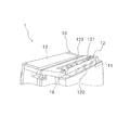
- FIG. 2 is a perspective view of the upper part of the main body of the air conditioner.
- an air outlet 11 is provided in the upper portion of the main body 10, and air that has been purified and conditioned through the air flow path A is blown out from the air outlet 11.
- the air blowing direction can be changed by the louver 12 installed at the opening of the air outlet 11.
- the louver 12 includes a partition blade 120, a first wind direction adjusting blade 121, and a second wind direction adjusting blade 122.
- the first wind direction adjusting blade 121 and the second wind direction adjusting blade 122 intersect with the partition blade 120 and are supported by the partition blade 120 so as to be tiltable with respect to the vertical direction.
- the louver 12 is driven by a stepping motor 19. In FIG. 1, the louver 12 is in a closed state, but when the operation is started, it is automatically opened directly above by the stepping motor 19.
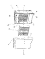
- FIG. 3 is a perspective view of the air conditioner removed from the air conditioner.
- the air purification unit 2 includes a cover 21, a filter 22, a deodorizing catalyst 23, a dust sensor 24, and an odor sensor 25.
- the filter 22 and the deodorizing catalyst 23 are detachably accommodated in the accommodating portion 20 provided in the main body 10, and the deodorizing catalyst 23 is located on the downstream side of the air flow of the filter 22.
- FIG. 4 is a perspective view of the operation panel.
- an operation on / off button 601 on the operation panel 60, an operation switching button 602, an air volume selection button 603, a humidity selection button 604, a course selection button 605, a timer selection button 606, an auto louver button 607, and a recommendation Buttons 608 are provided, and by pressing each button, a signal corresponding to the pressed button is input to the control unit 6 disposed below the operation panel 60.
- the control unit 6 includes a microcomputer and a memory.
- the operation on / off button 601 is a button for turning on / off the power supply to the air conditioner 1. After the power plug is inserted into an outlet, the operation is started when pressed, and the operation is performed when pressed again. Stop.
- the operation switching button 602 is a button for selecting an operation mode, and can select any one of “air cleaning”, “humidification”, and “dehumidification”.
- FIG. 5 is a circuit diagram of the sensor control device.
- an odor sensor 25 is a gas sensor having a detection element 25b that detects odors such as cigarettes.
- the detection element 25b is always warmed by the heater 25a in order to detect the gas concentration in the air.
- the control unit 6 includes a microcomputer 61 and a power supply circuit 62 in order to control the odor sensor 25.
- the microcomputer 61 includes a CPU and a memory, and monitors a detection signal from the odor sensor 25.
- the power supply circuit 62 includes a bridge circuit 62a made of a diode, an electrolytic capacitor 62b, and a transformer 62c, and a DC power supply Vb and a DC power supply Vc are generated from the AC power supply 100.
- the power supply circuit 62 has a switch circuit 63 on the power supply line to the odor sensor 25.
- the switch circuit 63 is a circuit that opens and closes an electrical connection between the DC power supply Vc and the heater 25a of the odor sensor 25, and includes a transistor 63a and a photocoupler 63b.
- the transistor 63a is connected between the DC power supply Vc and the heater 25a.
- the photocoupler 63b is connected to the base of the transistor 63a.
- the photocoupler 63b includes a phototransistor 631 and a light emitting diode 632.
- the phototransistor 631 is connected to the base of the transistor 66a.
- the light emitting diode 632 is connected between the DC power supply Vb and the microcomputer 61.
- the microcomputer 61 when the microcomputer 61 turns on the signal line to the light emitting diode 632, the light emitting diode 632 emits light, the phototransistor 631 is turned on, and the transistor 63a is also turned on, so that the DC power supply Vc is supplied to the heater 25a. Conversely, when the microcomputer 61 turns off the signal line to the light emitting diode 632, the light emitting diode 632 does not emit light, so that the phototransistor 631 does not conduct and the transistor 63a does not conduct. As a result, the DC power source Vc is not supplied to the heater 25a.
- the photocoupler 63b is used in the switch circuit 63 to cause the transistor 63a to perform a switching operation.
- the present invention is not limited to this, and a signal is directly input from the microcomputer 61 to the base of the transistor 63a. Then, the switch operation may be performed.
- ⁇ Operation of air conditioner> In FIG. 4, as long as the power plug is inserted into the outlet, the air conditioner 1 starts operation when the operation on / off button 601 is pressed, and stops operation when pressed again. Since the control unit 6 stores the operation mode before the stop as the operation mode, when the operation is resumed, the operation mode before the stop is executed until a new operation mode is selected by the operation switching button 602.
- the air conditioner 1 causes the odor sensor 25 to function in any of the “air cleaning”, “humidification” and “dehumidification” operation modes, and the microcomputer 61 always turns on the signal line of the light emitting diode 632.
- the DC power source Vc is supplied to the heater 25a.
- the DC power source Vc is supplied to the heater 25a of the odor sensor 25, power is consumed even when the operation is stopped unless the power plug is removed from the outlet.
- the power supply to the heater 25a is pulse-controlled in order to suppress so-called standby power consumption.
- the DC power source Vc is supplied to the heater 25a while the microcomputer 61 turns on the signal line to the light emitting diode 632, and the DC power source Vc is supplied while the signal line to the light emitting diode 632 is turned off. Since the heater 61 is pulse-energized when the microcomputer 61 turns on / off the signal line of the light-emitting diode 632, the power consumption is reduced as compared with continuous energization.
- the odor sensor 25 is a gas sensor, and detects the gas concentration in the air by bringing the detection element 25b heated by the heater 25a into contact with the air.
- the power supply circuit 62 has a switch circuit 63 on a power supply line to the heater 25a.
- the microcomputer 61 periodically sends a command signal to the switch circuit 63 and periodically opens and closes the power supply line, thereby changing the voltage supplied to the heater 25a to a pulse voltage. Yes. As a result, power consumption in the heater 25a is suppressed.
- the heater 25a is energized continuously while the air conditioner 1 is operating, and the heater 25a is pulsed while the air conditioner 1 is on standby.
- the present invention is not limited to this, and the heater 25a can be pulsed while the air conditioner 1 is operating and the air conditioner 1 is on standby.
- the energization time supplied to the heater 25a while the air conditioner 1 is on standby is shorter than the energization time supplied to the heater 25a while the air conditioner 1 is operating.
- the energization time per pulse supplied to the sensor in the second power supply state is set shorter than the energization time per pulse supplied to the sensor in the first power supply state.
- the pulse interval supplied to the sensor in the second power supply state is set wider than the pulse interval supplied to the sensor in the first power supply state.
- the supply form of pulses supplied to the sensor in the second power supply state is a supply form in which an arbitrary number of pulses are thinned out from the pulses supplied to the sensor in the first power supply state.
- the change of the energization time per pulse during the energization of the pulse can be performed while the energization period remains constant, or can be accompanied by a change in the energization period.
- the heater 25a is continuously energized while the air conditioner 1 is operating, and the heater 25a is pulsed while the air conditioner 1 is on standby.
- the present invention is not limited to this, and the heater 25a can be energized continuously while the air conditioner 1 is operating and while the air conditioner 1 is on standby.
- the energization voltage supplied to the heater 25a while the air conditioner 1 is on standby is smaller than the energization voltage supplied to the heater 25a while the air conditioner 1 is operating. As a result, while the air conditioner 1 is waiting, the power consumption in the heater 25a is reduced.
- the power supplied to the heater 25a can be increased or decreased based on the ambient temperature of the odor sensor 25. For example, when the ambient temperature is high, the temperature of the detection element 25b is likely to increase. Therefore, the power supplied to the heater 25a when the ambient temperature is high is smaller than the power supplied to the heater 25a when the ambient temperature is low. It may be.
- a temperature sensor 27 is newly arranged around the odor sensor 25, and the microcomputer 61 measures the ambient temperature of the odor sensor 25 via the temperature sensor 27.
- the existing temperature sensor of the air conditioner 1 may be used.
- the first method of increasing / decreasing the power is to increase / decrease the energization time per pulse at the time of pulse energization. .
- the second method of increasing / decreasing the power is to increase / decrease the energization voltage to the heater 25a.
- the third method of increasing or decreasing the power is to increase or decrease by thinning out the pulses energized to the heater 25a or by increasing or decreasing the number of thinning out.
- the increase / decrease in energization voltage is employ
- the power consumption of the sensor control circuit during standby can be suppressed, which is useful for an air conditioner and an air purifier.
- Control unit (sensor control device) 25 Smell Sensor 27 Temperature Sensor 61 Microcomputer 62 Power Supply Circuit (Power Supply Circuit) 63 Switch circuit
Landscapes
- Engineering & Computer Science (AREA)
- Chemical & Material Sciences (AREA)
- Combustion & Propulsion (AREA)
- Mechanical Engineering (AREA)
- General Engineering & Computer Science (AREA)
- Air Conditioning Control Device (AREA)
Abstract
空気調和機のセンサ制御装置であって、待機時の電力消費を抑制するセンサ制御装置を提供する。空気調和機(1)では、ニオイセンサ(25)は、ガスセンサであって、ヒータ(25a)で暖められた検知素子(25b)を空気と接触させて空気中のガス濃度を検知している。電源回路(62)は、ヒータ(25a)への電力供給ライン上にスイッチ回路(63)を有している。空気調和機(1)が待機状態のとき、マイコン(61)は、スイッチ回路(63)へ指令信号を周期的に送り、電力供給ラインを周期的に開閉することによって、ヒータ(25a)へ供給される電圧をパルス電圧にしている。
Description
本発明は、空気調和機のセンサへの電力供給を制御するセンサ制御装置に関する。
機器の待機電力を抑制する方法として、電源回路にスイッチ動作機構を設けて機器への電力供給を遮断する方法(例えば、特許文献1参照)が周知である。特許文献1に記載の電源回路では、電源回路からの電力供給が遮断されると、駆動系および制御系への電力供給が遮断されるので、待機電力の消費はほぼ0と考えてよい。但し、近年の機器の多機能化によって、多種の制御を実行するうえで電力供給を遮断する前の状態を記憶しておく必要があるため、制御系全体への電力供給を遮断することは不可能になっている。
例えば、空気調和機では、待機中であっても制御対象をセンサで監視する必要があるので、そのセンサの制御回路には常に電力が供給されている。このため、センサ制御回路での待機電力は、空気調和機の消費電力と比べれば極めて小さいが、地球的規模で普及しているので、実際には莫大な電力が消費されていることになる。それゆえ、センサ制御回路での待機電力の抑制が求められている。
例えば、空気調和機では、待機中であっても制御対象をセンサで監視する必要があるので、そのセンサの制御回路には常に電力が供給されている。このため、センサ制御回路での待機電力は、空気調和機の消費電力と比べれば極めて小さいが、地球的規模で普及しているので、実際には莫大な電力が消費されていることになる。それゆえ、センサ制御回路での待機電力の抑制が求められている。
本発明の課題は、空気調和機のセンサ制御装置であって、待機時の電力消費を抑制するセンサ制御装置を提供することにある。
第1発明に係る空気調和機のセンサ制御装置は、センサと、電力供給回路と、マイコンとを備えている。電力供給回路は、センサへ電力供給する。マイコンは、センサへの電力供給状態を変更するための指令信号を電力供給回路へ送る。電力供給状態には、センサに所定電力が供給される第1電力供給状態と、センサにその所定電力より小さい電力が供給される第2電力供給状態とが含まれている。空気調和機の待機時には、電力供給状態が第2電力供給状態へ変更される。このセンサ制御装置では、空気調和機の待機時に、センサで消費される電力量が低減される。
第2発明に係る空気調和機のセンサ制御装置は、第1発明に係る空気調和機のセンサ制御装置であって、第1電力供給状態でセンサに供給される電圧は連続的であり、第2電力供給状態でセンサに供給される電圧はパルス電圧である。
このセンサ制御装置では、センサに供給される電圧の供給時間を変更することで、多種の電力供給状態を提供することができるので、センサの特性に応じた節電が可能である。
このセンサ制御装置では、センサに供給される電圧の供給時間を変更することで、多種の電力供給状態を提供することができるので、センサの特性に応じた節電が可能である。
第3発明に係る空気調和機のセンサ制御装置は、第1発明に係る空気調和機のセンサ制御装置であって、第1電力供給状態でセンサに供給される電圧、及び第2電力供給状態でセンサに供給される電圧ともにパルス電圧である。第2電力供給状態の通電時間は、第1電力供給状態の通電時間よりも短く設定されている。このセンサ制御装置では、第1電力供給状態で消費電力量が低減され、第2電力供給状態でもさらに消費電力量が低減されるので、さらに節電となる。
第4発明に係る空気調和機のセンサ制御装置は、第3発明に係る空気調和機のセンサ制御装置であって、第2電力供給状態でセンサに供給される1パルス当たりの通電時間が、第1電力供給状態でセンサに供給される1パルス当たりの通電時間よりも短く設定されている。センサ制御装置では、第2電力供給状態での消費電力量がさらに低減されるので、さらに節電となる。
第5発明に係る空気調和機のセンサ制御装置は、第3発明に係る空気調和機のセンサ制御装置であって、第2電力供給状態でセンサに供給されるパルス間隔が、第1電力供給状態でセンサに供給されるパルス間隔よりも広く設定されている。このセンサ制御装置では、第2電力供給状態での消費電力量がさらに低減されるので、さらに節電となる。
第6発明に係る空気調和機のセンサ制御装置は、第3発明に係る空気調和機のセンサ制御装置であって、第2電力供給状態でセンサに供給されるパルスが間引かれている。このセンサ制御装置では、第2電力供給状態での消費電力量がさらに低減されるので、さらに節電となる。
第7発明に係る空気調和機のセンサ制御装置は、第1発明から第6発明のいずれか1つに係る空気調和機のセンサ制御装置であって、第2電力供給状態でセンサに供給される電圧は、第1電力供給状態でセンサに供給される電圧よりも小さく設定されている。
このセンサ制御装置では、センサに供給される電圧値を変更することで、多種の電力供給状態を提供することができるので、センサの特性に応じた節電が可能である。
このセンサ制御装置では、センサに供給される電圧値を変更することで、多種の電力供給状態を提供することができるので、センサの特性に応じた節電が可能である。
第8発明に係る空気調和機のセンサ制御装置は、第1発明から第7発明のいずれか1つに係る空気調和機のセンサ制御装置であって、センサがガスセンサである。ガスセンサは、ヒータで暖められた検知素子を空気と接触させて空気中のガス濃度を検知する。電力供給回路は、ヒータへ電力を供給する。このセンサ制御装置では、空気調和機の待機時に、ガスセンサのヒータで消費される電力量が低減される。
第9発明に係る空気調和機のセンサ制御装置は、第8発明に係る空気調和機のセンサ制御装置であって、電力供給回路が、ガスセンサへの電力供給ライン上にスイッチを有している。スイッチは、マイコンからの指令信号によって電力供給ラインを開閉する。
一般に、電力供給回路の電源を開閉するよりも、ガスセンサへの電力供給ラインを開閉するほうが、スイッチを構成する部品の定格を小さくすることができる。したがって、このセンサ制御装置では、部品コストの増大が抑制される。
一般に、電力供給回路の電源を開閉するよりも、ガスセンサへの電力供給ラインを開閉するほうが、スイッチを構成する部品の定格を小さくすることができる。したがって、このセンサ制御装置では、部品コストの増大が抑制される。
第10発明に係る空気調和機のセンサ制御装置は、第8発明に係る空気調和機のセンサ制御装置であって、ガスセンサの周囲温度を測定する温度センサをさらに備えている。第2電力供給状態でガスセンサに供給される電力は、温度センサの測定値に基づいて決定される。このセンサ制御装置では、ガスセンサに、周囲温度に応じた電力が供給されるので、無駄な電力供給が解消され節電となる。
第11発明に係る空気清浄機は、第8発明に係る空気調和機のセンサ制御装置を備えた空気清浄機である。この空気清浄機では、待機電力が小さい空気清浄機を実現することができる。
第1発明に係る空気調和機のセンサ制御装置では、空気調和機の待機時に、センサで消費される電力量が低減される。
第2発明に係る空気調和機のセンサ制御装置では、センサに供給される電圧の供給時間を変更することで、多種の電力供給状態を提供することができるので、センサの特性に応じた節電が可能である。
第3発明に係る空気調和機のセンサ制御装置では、第1電力供給状態で消費電力量が低減され、第2電力供給状態でもさらに消費電力量が低減されるので、さらに節電となる。
第4発明、第5発明および第6発明に係る空気調和機のセンサ制御装置では、第2電力供給状態での消費電力量がさらに低減されるので、さらに節電となる。
第7発明に係る空気調和機のセンサ制御装置では、センサに供給される電圧値を変更することで、多種の電力供給状態を提供することができるので、センサの特性に応じた節電が可能である。
第2発明に係る空気調和機のセンサ制御装置では、センサに供給される電圧の供給時間を変更することで、多種の電力供給状態を提供することができるので、センサの特性に応じた節電が可能である。
第3発明に係る空気調和機のセンサ制御装置では、第1電力供給状態で消費電力量が低減され、第2電力供給状態でもさらに消費電力量が低減されるので、さらに節電となる。
第4発明、第5発明および第6発明に係る空気調和機のセンサ制御装置では、第2電力供給状態での消費電力量がさらに低減されるので、さらに節電となる。
第7発明に係る空気調和機のセンサ制御装置では、センサに供給される電圧値を変更することで、多種の電力供給状態を提供することができるので、センサの特性に応じた節電が可能である。
第8発明に係る空気調和機のセンサ制御装置では、空気調和機の待機時に、ガスセンサのヒータで消費される電力量が低減される。
第9発明に係る空気調和機のセンサ制御装置では、スイッチを構成する部品の定格を小さくすることができるので、部品コストの増大が抑制される。
第10発明に係る空気調和機のセンサ制御装置では、ガスセンサに、周囲温度に応じた電力が供給されるので、無駄な電力供給が解消され節電となる。
第11発明に係る空気清浄機では、待機電力が小さい空気清浄機を実現することができる。
第9発明に係る空気調和機のセンサ制御装置では、スイッチを構成する部品の定格を小さくすることができるので、部品コストの増大が抑制される。
第10発明に係る空気調和機のセンサ制御装置では、ガスセンサに、周囲温度に応じた電力が供給されるので、無駄な電力供給が解消され節電となる。
第11発明に係る空気清浄機では、待機電力が小さい空気清浄機を実現することができる。
以下図面を参照しながら、本発明の実施形態について説明する。なお、以下の実施形態は、本発明の具体例であって、本発明の技術的範囲を限定するものではない。
<空気調和機>
図1は、本発明の一実施形態に係るセンサ制御装置を備えた空気調和機の斜視図である。図1において、空気調和機1では、空気清浄ユニット2、除湿ユニット3、加湿ユニット4、送風機5及び制御部6が、本体10に収納されている。本実施形態では、ユーザーが容易に空気調和機1を移動させることができるように、本体10の側面上部には取っ手7が設けられ、本体10の下面(室内の床面と対向する面)に、キャスター8が設けられている。
送風機5は、本体10に対して空気清浄ユニット2と反対側に位置しており、空気清浄ユニット2側から視たとき、空気清浄ユニット2、除湿ユニット3、加湿ユニット4、送風機5の順で並んでいる。送風機5が稼働しているとき、空気が空気清浄ユニット2側から吸い込まれて、除湿ユニット3を通過した後に加湿ユニット4を通過し送風機5に至る空気風路Aが形成される。
<空気調和機>
図1は、本発明の一実施形態に係るセンサ制御装置を備えた空気調和機の斜視図である。図1において、空気調和機1では、空気清浄ユニット2、除湿ユニット3、加湿ユニット4、送風機5及び制御部6が、本体10に収納されている。本実施形態では、ユーザーが容易に空気調和機1を移動させることができるように、本体10の側面上部には取っ手7が設けられ、本体10の下面(室内の床面と対向する面)に、キャスター8が設けられている。
送風機5は、本体10に対して空気清浄ユニット2と反対側に位置しており、空気清浄ユニット2側から視たとき、空気清浄ユニット2、除湿ユニット3、加湿ユニット4、送風機5の順で並んでいる。送風機5が稼働しているとき、空気が空気清浄ユニット2側から吸い込まれて、除湿ユニット3を通過した後に加湿ユニット4を通過し送風機5に至る空気風路Aが形成される。
図2は、空気調和機の本体上部の斜視図である。図2において、本体10の上部には吹出口11が設けられており、空気流路Aを経て浄化され調湿された空気が吹出口11から吹き出される。空気の吹き出し方向は、吹出口11の開口部に設置されたルーバー12によって変更することができる。
ルーバー12は、仕切羽根120と、第1風向調整羽根121と、第2風向調整羽根122とを有している。第1風向調整羽根121及び第2風向調整羽根122は、仕切羽根120と交差し、且つ鉛直方向に対して傾斜自在に仕切羽根120に支持されている。ルーバー12は、ステッピングモータ19によって駆動される。図1では、ルーバー12が閉じた状態であるが、運転を開始するとステッピングモータ19によって自動的に真上に開く。
ルーバー12は、仕切羽根120と、第1風向調整羽根121と、第2風向調整羽根122とを有している。第1風向調整羽根121及び第2風向調整羽根122は、仕切羽根120と交差し、且つ鉛直方向に対して傾斜自在に仕切羽根120に支持されている。ルーバー12は、ステッピングモータ19によって駆動される。図1では、ルーバー12が閉じた状態であるが、運転を開始するとステッピングモータ19によって自動的に真上に開く。
さらに、本体10の上部には操作パネル60(図1参照)が設けられており、保護カバー13によって保護されている。その操作パネル60の下方に制御部6(図1参照)が位置しており、操作パネル60から入力される信号に基づいて、空気清浄ユニット2、除湿ユニット3、加湿ユニット4、送風機5及びルーバー12が制御される。運転モードは、操作パネル60上の運転切換ボタンによって切り替えられる。
図3は、空気調和機から空気清浄ユニットを取り外した斜視図である。図3において、空気清浄ユニット2は、カバー21と、フィルタ22と、脱臭触媒23と、ホコリセンサ24と、ニオイセンサ25とを有している。フィルタ22と脱臭触媒23は、本体10に設けられた収納部20に脱着可能に収納されており、脱臭触媒23がフィルタ22の空気流下流側に位置する。
図3は、空気調和機から空気清浄ユニットを取り外した斜視図である。図3において、空気清浄ユニット2は、カバー21と、フィルタ22と、脱臭触媒23と、ホコリセンサ24と、ニオイセンサ25とを有している。フィルタ22と脱臭触媒23は、本体10に設けられた収納部20に脱着可能に収納されており、脱臭触媒23がフィルタ22の空気流下流側に位置する。
脱臭触媒23は、フィルタ22を通過してきた空気から臭いや有害ガスを吸着し、分解する。ホコリセンサ24は、本体10の側面上部に設けられ、ニオイセンサ25は、収納部20の上方に設けられている。
<操作パネル60>
図4は、操作パネルの斜視図である。図4において、操作パネル60上には、運転入/切ボタン601、運転切換ボタン602、風量選択ボタン603、湿度選択ボタン604、コース選択ボタン605、タイマー選択ボタン606、オートルーバーボタン607、及びおすすめボタン608が設けられており、各ボタンを押すことによって、押されたボタンに対応した信号が、操作パネル60の下方に配置された制御部6に入力される。なお、制御部6は、マイコンとメモリを内蔵している。
<操作パネル60>
図4は、操作パネルの斜視図である。図4において、操作パネル60上には、運転入/切ボタン601、運転切換ボタン602、風量選択ボタン603、湿度選択ボタン604、コース選択ボタン605、タイマー選択ボタン606、オートルーバーボタン607、及びおすすめボタン608が設けられており、各ボタンを押すことによって、押されたボタンに対応した信号が、操作パネル60の下方に配置された制御部6に入力される。なお、制御部6は、マイコンとメモリを内蔵している。
例えば、運転入/切ボタン601は、空気調和機1への電力供給をオン・オフするボタンであり、電源プラグをコンセントに差し込んだ後、押されると運転を開始し、再度押されると運転を停止する。また、運転切換ボタン602は、運転モードを選択するボタンであり、「空気清浄」、「加湿」及び「除湿」のいずれか1つを選択することができる。
<センサ制御装置>
図5は、センサ制御装置の回路図である。図5において、ニオイセンサ25は、タバコなどのニオイを検知する検知素子25bを有するガスセンサである。検知素子25bは、空気中のガス濃度を検知するために、常に、ヒータ25aで暖められている。
制御部6は、ニオイセンサ25を制御するために、マイコン61及び電源回路62を備えている。マイコン61は、CPUとメモリを内蔵し、ニオイセンサ25の検知信号を監視している。
<センサ制御装置>
図5は、センサ制御装置の回路図である。図5において、ニオイセンサ25は、タバコなどのニオイを検知する検知素子25bを有するガスセンサである。検知素子25bは、空気中のガス濃度を検知するために、常に、ヒータ25aで暖められている。
制御部6は、ニオイセンサ25を制御するために、マイコン61及び電源回路62を備えている。マイコン61は、CPUとメモリを内蔵し、ニオイセンサ25の検知信号を監視している。
電源回路62は、ダイオードから成るブリッジ回路62a、電解コンデンサー62b及び変圧器62cを有し、交流電源100から直流電源Vb及び直流電源Vcが生成される。電源回路62は、ニオイセンサ25への電力供給ライン上に、スイッチ回路63を有している。スイッチ回路63は、直流電源Vcとニオイセンサ25のヒータ25aとの間の電気的接続を開閉する回路であり、トランジスタ63aとフォトカプラ63bとから成る。トランジスタ63aは、直流電源Vcとヒータ25aとの間に接続される。フォトカプラ63bは、トランジスタ63aのベースに接続されている。
フォトカプラ63bは、フォトトランジスタ631と発光ダイオード632を内蔵しており、実際には、フォトトランジスタ631がトランジスタ66aのベースに接続されている。発光ダイオード632は、直流電源Vbとマイコン61との間に接続されている。
フォトカプラ63bは、フォトトランジスタ631と発光ダイオード632を内蔵しており、実際には、フォトトランジスタ631がトランジスタ66aのベースに接続されている。発光ダイオード632は、直流電源Vbとマイコン61との間に接続されている。
例えば、マイコン61が発光ダイオード632への信号ラインをオンさせると、発光ダイオード632が発光してフォトトランジスタ631が導通し、トランジスタ63aも導通するので、直流電源Vcがヒータ25aに供給される。
逆に、マイコン61が発光ダイオード632への信号ラインをオフさせると、発光ダイオード632が発光しないので、フォトトランジスタ631は導通せずトランジスタ63aも導通しない。その結果、直流電源Vcがヒータ25aに供給されない。
なお、本実施形態では、スイッチ回路63にフォトカプラ63bを使用してトランジスタ63aにスイッチ動作をさせているが、これに限定されるものではなく、マイコン61からトランジスタ63aのベースに直接信号を入力してスイッチ動作をさせてもよい。
<空気調和機の動作>
図4において、空気調和機1では、電源プラグがコンセントに差し込まれている限り、運転入/切ボタン601が押されると運転を開始し、再度押されると運転を停止する。運転モードは停止前の運転モードを制御部6が記憶しているので、運転が再開されると、運転切換ボタン602で新たに運転モードを選択するまでは、停止前の運転モードを実行する。空気調和機1は、「空気清浄」、「加湿」及び「除湿」のいずれの運転モードであっても、ニオイセンサ25を機能させており、常に、マイコン61が発光ダイオード632の信号ラインをオンして、ヒータ25aに直流電源Vcを供給している。
逆に、マイコン61が発光ダイオード632への信号ラインをオフさせると、発光ダイオード632が発光しないので、フォトトランジスタ631は導通せずトランジスタ63aも導通しない。その結果、直流電源Vcがヒータ25aに供給されない。
なお、本実施形態では、スイッチ回路63にフォトカプラ63bを使用してトランジスタ63aにスイッチ動作をさせているが、これに限定されるものではなく、マイコン61からトランジスタ63aのベースに直接信号を入力してスイッチ動作をさせてもよい。
<空気調和機の動作>
図4において、空気調和機1では、電源プラグがコンセントに差し込まれている限り、運転入/切ボタン601が押されると運転を開始し、再度押されると運転を停止する。運転モードは停止前の運転モードを制御部6が記憶しているので、運転が再開されると、運転切換ボタン602で新たに運転モードを選択するまでは、停止前の運転モードを実行する。空気調和機1は、「空気清浄」、「加湿」及び「除湿」のいずれの運転モードであっても、ニオイセンサ25を機能させており、常に、マイコン61が発光ダイオード632の信号ラインをオンして、ヒータ25aに直流電源Vcを供給している。
<待機時のニオイセンサの消費電力低減>
ニオイセンサ25のヒータ25aには、直流電源Vcが供給されているので、電源プラグをコンセントから抜かない限り、運転停止時でも電力が消費されている。本実施形態では、電源プラグがコンセントに差し込まれた状態で運転が停止しているとき、いわゆる待機時の電力消費を抑えるために、ヒータ25aへの電力供給をパルス制御している。
パルス制御は、マイコン61が発光ダイオード632への信号ラインをオンさせている間、ヒータ25aに直流電源Vcが供給され、発光ダイオード632への信号ラインをオフさせている間、直流電源Vcが供給されないことを利用したものであって、マイコン61が、発光ダイオード632の信号ラインをオン・オフさせることによって、ヒータ25aはパルス通電されるので、電力消費量が連続通電に比較して小さくなる。
ニオイセンサ25のヒータ25aには、直流電源Vcが供給されているので、電源プラグをコンセントから抜かない限り、運転停止時でも電力が消費されている。本実施形態では、電源プラグがコンセントに差し込まれた状態で運転が停止しているとき、いわゆる待機時の電力消費を抑えるために、ヒータ25aへの電力供給をパルス制御している。
パルス制御は、マイコン61が発光ダイオード632への信号ラインをオンさせている間、ヒータ25aに直流電源Vcが供給され、発光ダイオード632への信号ラインをオフさせている間、直流電源Vcが供給されないことを利用したものであって、マイコン61が、発光ダイオード632の信号ラインをオン・オフさせることによって、ヒータ25aはパルス通電されるので、電力消費量が連続通電に比較して小さくなる。
<特徴>
空気調和機1では、ニオイセンサ25は、ガスセンサであって、ヒータ25aで暖められた検知素子25bを空気と接触させて空気中のガス濃度を検知している。電源回路62は、ヒータ25aへの電力供給ライン上にスイッチ回路63を有している。空気調和機1が待機状態のとき、マイコン61は、スイッチ回路63へ指令信号を周期的に送り、電力供給ラインを周期的に開閉することによって、ヒータ25aへ供給される電圧をパルス電圧にしている。その結果、ヒータ25aでの電力消費が抑制される。
<変形例1>
上記実施形態では、空気調和機1が運転している間、ヒータ25aは連続通電され、空気調和機1が待機している間、ヒータ25aはパルス通電される。しかし、それに限定されるものではなく、空気調和機1が運転している間、および空気調和機1が待機している間ともに、ヒータ25aにパルス通電されることも可能である。但し、空気調和機1が待機している間ヒータ25aに供給される通電時間は、空気調和機1が運転している間ヒータ25aに供給される通電時間よりも短い。
空気調和機1では、ニオイセンサ25は、ガスセンサであって、ヒータ25aで暖められた検知素子25bを空気と接触させて空気中のガス濃度を検知している。電源回路62は、ヒータ25aへの電力供給ライン上にスイッチ回路63を有している。空気調和機1が待機状態のとき、マイコン61は、スイッチ回路63へ指令信号を周期的に送り、電力供給ラインを周期的に開閉することによって、ヒータ25aへ供給される電圧をパルス電圧にしている。その結果、ヒータ25aでの電力消費が抑制される。
<変形例1>
上記実施形態では、空気調和機1が運転している間、ヒータ25aは連続通電され、空気調和機1が待機している間、ヒータ25aはパルス通電される。しかし、それに限定されるものではなく、空気調和機1が運転している間、および空気調和機1が待機している間ともに、ヒータ25aにパルス通電されることも可能である。但し、空気調和機1が待機している間ヒータ25aに供給される通電時間は、空気調和機1が運転している間ヒータ25aに供給される通電時間よりも短い。
具体例として、第2電力供給状態でセンサに供給される1パルス当たりの通電時間が、第1電力供給状態でセンサに供給される1パルス当たりの通電時間よりも短く設定されている。或は、第2電力供給状態でセンサに供給されるパルス間隔が、第1電力供給状態でセンサに供給されるパルス間隔よりも広く設定されている。或は、第2電力供給状態でセンサに供給されるパルスの供給形態が、第1電力供給状態でセンサに供給されるパルスから任意の数のパルスが間引かれた供給形態である。
変形例1では、空気調和機1が待機している間のヒータ25aの電力消費量だけでなく、空気調和機1が運転している間のヒータ25aの電力消費量も減少する。なお、パルス通電時の1パルス当たりの通電時間の変更は、通電の周期が一定のままで行われることも、通電の周期の変更を伴うことも可能である。
変形例1では、空気調和機1が待機している間のヒータ25aの電力消費量だけでなく、空気調和機1が運転している間のヒータ25aの電力消費量も減少する。なお、パルス通電時の1パルス当たりの通電時間の変更は、通電の周期が一定のままで行われることも、通電の周期の変更を伴うことも可能である。
<変形例2>
上記実施形態では、空気調和機1が運転している間は、ヒータ25aは連続通電され、空気調和機1が待機している間は、ヒータ25aはパルス通電される。しかし、それに限定されるものではなく、空気調和機1が運転している間、および空気調和機1が待機している間ともに、ヒータ25aに連続通電されることも可能である。但し、空気調和機1が待機している間ヒータ25aに供給される通電電圧は、空気調和機1が運転している間ヒータ25aに供給される通電電圧よりも小さい。その結果、空気調和機1が待機している間、ヒータ25aでの電力消費量が減少する。
<変形例3>
空気調和機1が待機しているとき、ニオイセンサ25の周囲温度に基づいて、ヒータ25aへ供給される電力を増減することも可能である。例えば、周囲温度が高いとき、検知素子25bは温度上昇し易くなるので、周囲温度が高いときのヒータ25aへ供給される電力は、周囲温度が低くいときのヒータ25aへ供給される電力より小さくなってもよい。第3変形例では、ニオイセンサ25の周辺に新たに温度センサ27を配置し、マイコン61が温度センサ27を介してニオイセンサ25の周囲温度を測定している。但し、空気調和機1の既存の温度センサを利用してもよい。
上記実施形態では、空気調和機1が運転している間は、ヒータ25aは連続通電され、空気調和機1が待機している間は、ヒータ25aはパルス通電される。しかし、それに限定されるものではなく、空気調和機1が運転している間、および空気調和機1が待機している間ともに、ヒータ25aに連続通電されることも可能である。但し、空気調和機1が待機している間ヒータ25aに供給される通電電圧は、空気調和機1が運転している間ヒータ25aに供給される通電電圧よりも小さい。その結果、空気調和機1が待機している間、ヒータ25aでの電力消費量が減少する。
<変形例3>
空気調和機1が待機しているとき、ニオイセンサ25の周囲温度に基づいて、ヒータ25aへ供給される電力を増減することも可能である。例えば、周囲温度が高いとき、検知素子25bは温度上昇し易くなるので、周囲温度が高いときのヒータ25aへ供給される電力は、周囲温度が低くいときのヒータ25aへ供給される電力より小さくなってもよい。第3変形例では、ニオイセンサ25の周辺に新たに温度センサ27を配置し、マイコン61が温度センサ27を介してニオイセンサ25の周囲温度を測定している。但し、空気調和機1の既存の温度センサを利用してもよい。
電力の増減方法の第1方法は、パルス通電時の1パルス当たりの通電時間の増減であり、通電の周期が一定のままで行われることも、通電の周期の増減を伴うことも可能である。電力の増減方法の第2方法は、ヒータ25aへの通電電圧の増減である。電力の増減方法の第3方法は、ヒータ25aに通電されるパルスを間引くことによる、或は間引く数を増減させることによる増減である。なお、変形例3が変形例2に適用される場合は、電力の増減方法として、通電電圧の増減が採用される。
以上のように、本発明によれば、待機時のセンサ制御回路の消費電力を抑えることができるので、空気調和装置および空気清浄機に有用である。
6 制御部(センサ制御装置)
25 ニオイセンサ
27 温度センサ
61 マイコン
62 電源回路(電力供給回路)
63 スイッチ回路
25 ニオイセンサ
27 温度センサ
61 マイコン
62 電源回路(電力供給回路)
63 スイッチ回路
Claims (11)
- 空気調和機のセンサ制御装置であって、
センサ(25)と
前記センサ(25)へ電力供給する電力供給回路(62)と、
前記センサ(25)への電力供給状態を変更するための指令信号を前記電力供給回路(62)へ送るマイコン(61)と、
を備え、
前記電力供給状態には、
前記センサ(25)に所定電力が供給される第1電力供給状態と、
前記センサ(25)に前記所定電力より小さい電力が供給される第2電力供給状態と、
が含まれており、
前記空気調和機の待機時には、前記電力供給状態が前記第2電力供給状態へ変更される、
空気調和機のセンサ制御装置。 - 前記第1電力供給状態で前記センサ(25)に供給される電圧は連続的であり、前記第2電力供給状態で前記センサ(25)に供給される電圧はパルス電圧である、
請求項1に記載の空気調和機のセンサ制御装置。 - 前記第1電力供給状態で前記センサ(25)に供給される電圧、及び前記第2電力供給状態で前記センサ(25)に供給される電圧ともにパルス電圧であり、
前記第2電力供給状態の通電時間は、前記第1電力供給状態の通電時間よりも短く設定されている、
請求項1に記載の空気調和機のセンサ制御装置。 - 前記第2電力供給状態で前記センサ(25)に供給される1パルス当たりの通電時間は、前記第1電力供給状態で前記センサ(25)に供給される1パルス当たりの通電時間よりも短く設定されている、
請求項3に記載の空気調和機のセンサ制御装置。 - 前記第2電力供給状態で前記センサ(25)に供給されるパルス間隔は、前記第1電力供給状態で前記センサ(25)に供給されるパルス間隔よりも広く設定されている、
請求項3に記載の空気調和機のセンサ制御装置。 - 前記第2電力供給状態で前記センサ(25)に供給されるパルスが間引かれている、
請求項3に記載の空気調和機のセンサ制御装置。 - 前記第2電力供給状態で前記センサ(25)に供給される電圧は、前記第1電力供給状態で前記センサ(25)に供給される電圧よりも小さく設定されている、
請求項1から請求項6のいずれか1項に記載の空気調和機のセンサ制御装置。 - 前記センサ(25)は、ヒータ(25a)で暖められた検知素子(25b)を空気と接触させて前記空気中のガス濃度を検知するガスセンサ(25)であり、
前記電力供給回路(62)は、前記ヒータ(25a)へ電力を供給する、
請求項1から請求項7のいずれか1項に記載の空気調和機のセンサ制御装置。 - 前記電力供給回路(62)は、前記ガスセンサ(25)への電力供給ライン上にスイッチ(63)を有し、
前記スイッチ(63)は、前記マイコン(61)からの前記指令信号によって前記電力供給ラインを開閉する、
請求項8に記載の空気調和機のセンサ制御装置。 - 前記ガスセンサ(25)の周囲温度を測定する温度センサ(27)をさらに備え、
前記第2電力供給状態で前記ガスセンサ(25)に供給される電力は、前記温度センサ(27)の測定値に基づいて決定される、
請求項8に記載の空気調和機のセンサ制御装置。 - 請求項8に記載の空気調和機のセンサ制御装置を備えた、
空気清浄機。
Applications Claiming Priority (2)
| Application Number | Priority Date | Filing Date | Title |
|---|---|---|---|
| JP2008224544A JP2010060175A (ja) | 2008-09-02 | 2008-09-02 | 空気調和機のセンサ制御装置 |
| JP2008-224544 | 2008-09-02 |
Publications (1)
| Publication Number | Publication Date |
|---|---|
| WO2010026720A1 true WO2010026720A1 (ja) | 2010-03-11 |
Family
ID=41796906
Family Applications (1)
| Application Number | Title | Priority Date | Filing Date |
|---|---|---|---|
| PCT/JP2009/004197 Ceased WO2010026720A1 (ja) | 2008-09-02 | 2009-08-28 | 空気調和機のセンサ制御装置 |
Country Status (2)
| Country | Link |
|---|---|
| JP (1) | JP2010060175A (ja) |
| WO (1) | WO2010026720A1 (ja) |
Citations (3)
| Publication number | Priority date | Publication date | Assignee | Title |
|---|---|---|---|---|
| JP2001091018A (ja) * | 1999-09-17 | 2001-04-06 | Sharp Corp | 空気清浄装置 |
| JP2003270201A (ja) * | 2002-03-14 | 2003-09-25 | Matsushita Electric Ind Co Ltd | ガスセンサ |
| JP2007309751A (ja) * | 2006-05-17 | 2007-11-29 | Ngk Spark Plug Co Ltd | ガス検出装置 |
-
2008
- 2008-09-02 JP JP2008224544A patent/JP2010060175A/ja active Pending
-
2009
- 2009-08-28 WO PCT/JP2009/004197 patent/WO2010026720A1/ja not_active Ceased
Patent Citations (3)
| Publication number | Priority date | Publication date | Assignee | Title |
|---|---|---|---|---|
| JP2001091018A (ja) * | 1999-09-17 | 2001-04-06 | Sharp Corp | 空気清浄装置 |
| JP2003270201A (ja) * | 2002-03-14 | 2003-09-25 | Matsushita Electric Ind Co Ltd | ガスセンサ |
| JP2007309751A (ja) * | 2006-05-17 | 2007-11-29 | Ngk Spark Plug Co Ltd | ガス検出装置 |
Also Published As
| Publication number | Publication date |
|---|---|
| JP2010060175A (ja) | 2010-03-18 |
Similar Documents
| Publication | Publication Date | Title |
|---|---|---|
| ES2891363T3 (es) | Sistema de ventilación | |
| US7040101B2 (en) | Air refining device and ion generator used for the device | |
| KR101307897B1 (ko) | 차량용 공조시스템 | |
| WO2019150735A1 (ja) | 空気清浄装置、及び空気清浄方法 | |
| CN104296233B (zh) | 电暖气 | |
| US6178765B1 (en) | Air conditioner having air cleaning function | |
| JP4742572B2 (ja) | 空気調和機の空気清浄装置 | |
| JP2004060998A (ja) | 省エネ型機器 | |
| JP2003056873A (ja) | 加湿機能付き電気暖房機器 | |
| JP2008036257A (ja) | 空気清浄機 | |
| JP5211820B2 (ja) | 空気調和機 | |
| JP2009262020A (ja) | 空気清浄機 | |
| JP2002089940A (ja) | 空気調和機 | |
| JP6059606B2 (ja) | 送風装置 | |
| JP2010060175A (ja) | 空気調和機のセンサ制御装置 | |
| KR20170068913A (ko) | 공기청정기 및 이의 전원 제어 방법 | |
| JP2010063303A (ja) | モータ駆動装置 | |
| JP6529869B2 (ja) | 加湿機能付温風暖房機 | |
| JP2020041750A (ja) | 電気機器及びその制御方法 | |
| JP2013015302A (ja) | 空気清浄機 | |
| KR20050039112A (ko) | 공기청정 겸용 가습장치의 제어 방법 | |
| JP2017062091A (ja) | 空気清浄機 | |
| JP2017032235A (ja) | 暖房機 | |
| KR100789711B1 (ko) | 공기청정기의 제어방법 | |
| JP4985815B2 (ja) | 空気調和機の空気清浄装置 |
Legal Events
| Date | Code | Title | Description |
|---|---|---|---|
| 121 | Ep: the epo has been informed by wipo that ep was designated in this application |
Ref document number: 09811250 Country of ref document: EP Kind code of ref document: A1 |
|
| NENP | Non-entry into the national phase |
Ref country code: DE |
|
| 122 | Ep: pct application non-entry in european phase |
Ref document number: 09811250 Country of ref document: EP Kind code of ref document: A1 |