WO2010023887A1 - 3次元表示時における指示位置設定装置および方法並びにプログラム - Google Patents
3次元表示時における指示位置設定装置および方法並びにプログラム Download PDFInfo
- Publication number
- WO2010023887A1 WO2010023887A1 PCT/JP2009/004111 JP2009004111W WO2010023887A1 WO 2010023887 A1 WO2010023887 A1 WO 2010023887A1 JP 2009004111 W JP2009004111 W JP 2009004111W WO 2010023887 A1 WO2010023887 A1 WO 2010023887A1
- Authority
- WO
- WIPO (PCT)
- Prior art keywords
- instruction
- display
- control range
- dimensional display
- displayed
- Prior art date
Links
Images


Classifications
-
- G—PHYSICS
- G06—COMPUTING OR CALCULATING; COUNTING
- G06F—ELECTRIC DIGITAL DATA PROCESSING
- G06F3/00—Input arrangements for transferring data to be processed into a form capable of being handled by the computer; Output arrangements for transferring data from processing unit to output unit, e.g. interface arrangements
- G06F3/01—Input arrangements or combined input and output arrangements for interaction between user and computer
- G06F3/03—Arrangements for converting the position or the displacement of a member into a coded form
- G06F3/041—Digitisers, e.g. for touch screens or touch pads, characterised by the transducing means
- G06F3/0416—Control or interface arrangements specially adapted for digitisers
- G06F3/0418—Control or interface arrangements specially adapted for digitisers for error correction or compensation, e.g. based on parallax, calibration or alignment
- G06F3/04186—Touch location disambiguation
-
- G—PHYSICS
- G06—COMPUTING OR CALCULATING; COUNTING
- G06F—ELECTRIC DIGITAL DATA PROCESSING
- G06F3/00—Input arrangements for transferring data to be processed into a form capable of being handled by the computer; Output arrangements for transferring data from processing unit to output unit, e.g. interface arrangements
- G06F3/01—Input arrangements or combined input and output arrangements for interaction between user and computer
- G06F3/03—Arrangements for converting the position or the displacement of a member into a coded form
- G06F3/041—Digitisers, e.g. for touch screens or touch pads, characterised by the transducing means
- G06F3/0416—Control or interface arrangements specially adapted for digitisers
- G06F3/0418—Control or interface arrangements specially adapted for digitisers for error correction or compensation, e.g. based on parallax, calibration or alignment
-
- G—PHYSICS
- G06—COMPUTING OR CALCULATING; COUNTING
- G06F—ELECTRIC DIGITAL DATA PROCESSING
- G06F3/00—Input arrangements for transferring data to be processed into a form capable of being handled by the computer; Output arrangements for transferring data from processing unit to output unit, e.g. interface arrangements
- G06F3/01—Input arrangements or combined input and output arrangements for interaction between user and computer
- G06F3/048—Interaction techniques based on graphical user interfaces [GUI]
- G06F3/0487—Interaction techniques based on graphical user interfaces [GUI] using specific features provided by the input device, e.g. functions controlled by the rotation of a mouse with dual sensing arrangements, or of the nature of the input device, e.g. tap gestures based on pressure sensed by a digitiser
- G06F3/0488—Interaction techniques based on graphical user interfaces [GUI] using specific features provided by the input device, e.g. functions controlled by the rotation of a mouse with dual sensing arrangements, or of the nature of the input device, e.g. tap gestures based on pressure sensed by a digitiser using a touch-screen or digitiser, e.g. input of commands through traced gestures
-
- G—PHYSICS
- G06—COMPUTING OR CALCULATING; COUNTING
- G06F—ELECTRIC DIGITAL DATA PROCESSING
- G06F2203/00—Indexing scheme relating to G06F3/00 - G06F3/048
- G06F2203/048—Indexing scheme relating to G06F3/048
- G06F2203/04802—3D-info-object: information is displayed on the internal or external surface of a three dimensional manipulable object, e.g. on the faces of a cube that can be rotated by the user
Definitions
- the present invention relates to an instruction position setting device and method and an instruction position setting method for setting an instruction position on an indication area included in an instruction image on a display surface when an instruction image for receiving a predetermined instruction is displayed. It relates to a program to be executed.
- stereoscopic viewing can be performed using parallax by combining a plurality of images and displaying them three-dimensionally.
- a plurality of images are acquired by photographing the same subject from different positions using a plurality of cameras, and the plurality of images are three-dimensionally obtained using the parallax of the subjects included in the plurality of images. It can be generated by displaying.
- a plurality of images can be arranged side by side to perform three-dimensional display.
- a plurality of images are overlapped with different colors such as red and blue, or a plurality of images are overlapped with different polarization directions, and a plurality of images are combined to perform three-dimensional display.
- stereoscopic viewing can be performed by using image separation glasses such as red-blue glasses and polarizing glasses to fuse the three-dimensionally displayed image with the auto-focus function of the eyes (an anaglyph method, a polarizing filter method). ).
- a plurality of images on a three-dimensional display monitor that can be stereoscopically viewed and stereoscopically viewed without using polarized glasses or the like, as in the parallax barrier method and the lenticular method.
- three-dimensional display is performed by cutting a plurality of images into strips in the vertical direction and arranging them alternately.
- a method of performing three-dimensional display by alternately displaying the left and right images while changing the light beam direction of the left and right images by using image separation glasses or attaching an optical element to the liquid crystal has been proposed. (Scan backlight method).
- a touch position system that detects the position indicated on the screen by combining the monitor and the position detection device detects the indicated position with respect to the image displayed on the monitor, and outputs a signal indicating the indicated position.
- An instruction input device has been proposed.
- a method for detecting an indicated position on an image displayed on a monitor without contact has been proposed.
- a method of arranging a touch panel type input device on a three-dimensional display monitor has been proposed (see Patent Document 2). According to this method, various inputs can be performed by instructions to the monitor while performing a three-dimensional display.
- the present invention has been made in view of the above circumstances, and an object thereof is to accurately detect a designated position on a screen on which three-dimensional display is performed.
- the pointing position setting device in the three-dimensional display includes a display means for displaying a pointing image capable of two-dimensional display and three-dimensional display, including at least one pointing area for receiving a predetermined instruction.
- a designated position detecting means for detecting the designated designated position;
- Control range setting means for setting a control range on the display means corresponding to the instruction area of the instruction image displayed on the display means, wherein the instruction image is displayed two-dimensionally and the 3 Control range setting means for changing the position of the control range when the dimensions are displayed is provided.
- control range setting means may determine the position where the pointing area is visually recognized by the stereoscopic view and the position of the control range during the three-dimensional display of the pointing image. It is good also as a means to match.
- the position of the control range in the three-dimensional display of the instruction image relative to the position of the pointing region in the two-dimensional display of the pointing image It further comprises storage means for storing the horizontal movement amount at
- the control range setting means may be means for changing the position of the control range based on the horizontal movement amount stored in the storage means.
- the control range setting means obtains temporary designated position information by accepting an instruction to the designated area when the designated image is displayed in the three-dimensional manner. Calculating the horizontal movement amount on the display means of the temporary designated position at the time of the three-dimensional display with respect to the position of the designated area at the time of the two-dimensional display of the designated image, Based on this, it may be a means for changing the position of the control range.
- control range setting unit may be a unit that reads a horizontal movement amount corresponding to the specified person from the storage unit and changes the position of the control range based on the read horizontal movement amount.
- the designated position setting device according to the present invention may be used simultaneously by a plurality of persons. For this reason, when using the pointing position setting device according to the present invention simultaneously with a plurality of persons, the control range setting means reads out the horizontal movement amount corresponding to each of the plurality of persons used at the same time from the storage means and reads them out. The position of the control range for a plurality of persons may be set based on the horizontal movement amount.
- the pointing position setting method in the three-dimensional display includes a display means for displaying a pointing image capable of two-dimensional display and three-dimensional display, including at least one pointing area for receiving a predetermined instruction.
- the indicated position is detected by the indicated position detection means,
- the control range on the display unit corresponding to the instruction area of the instruction image displayed on the display unit the instruction image is displayed in the two-dimensional display and the three-dimensional display.
- the position of the control range is changed.
- the position of the control range on the display unit corresponding to the instruction area of the instruction image is changed depending on whether the instruction image is displayed two-dimensionally or three-dimensionally. For this reason, even if the instruction image is displayed in three dimensions, the position corresponding to the position where the instruction area by stereoscopic vision is visually recognized can be set as the control range, and as a result, the display means performing the three-dimensional display The indicated position can be accurately detected on the display screen.
- the two-dimensional display of the instruction image can be reduced as compared with the case of storing the position of the designated area during both display and three-dimensional display.
- the position of the control range can be set according to the stereoscopic effect of the person who has given the instruction, and as a result, the instruction is given more accurately.
- the position can be detected.
- the calculated horizontal movement amount is stored in association with a plurality of persons observing the instruction image, the person observing the instruction image is specified, and the horizontal movement amount corresponding to the specified person is determined.
- the position of the control range is set according to the stereoscopic effect of each of a plurality of persons by changing the position of the control range depending on whether the instruction image is displayed in two dimensions or in three dimensions. As a result, the indicated position can be detected more accurately.
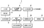
- FIG. 1 is a schematic block diagram showing a configuration of an instruction input device to which an instruction position setting device according to a first embodiment of the present invention is applied.
- the instruction input device 1 according to the present embodiment is for inputting various instructions shown in a displayed instruction image to an external device when a user touches the screen with a finger.
- Unit 2 input unit 3, input coordinate acquisition unit 4, display control unit 5, image input unit 6, three-dimensional processing unit 7, display switching unit 8, input control unit 9, range setting unit 10, and storage unit 11.
- the display unit 2 includes a liquid crystal monitor or the like, and can display a three-dimensional display or a two-dimensional display of an instruction image input to the apparatus 1 from an image input unit 6 described later.
- the input unit 3 includes a touch panel and is a means for selecting an instruction area such as a button included in the instruction image displayed on the display unit 2. Specifically, when the user touches the input unit 3, information on the coordinate position of that part is output to the input coordinate acquisition unit 4.
- the coordinate position is a coordinate whose origin is a predetermined position (for example, the upper left corner) on the input unit 3.
- an input device that detects the indicated position in a non-contact manner as described in Patent Document 1, an input device that optically detects the indicated position indicated by using a laser pointer or the like, A light-shielding type input that detects light-emitting elements such as LEDs on the vertical and horizontal walls around the surface of the display unit 2 and light-receiving elements on the opposite side, and detects the indicated position according to the position of light blocked when the user touches the screen.
- a plurality of image sensors are arranged around the device and the display unit 2, an image of a finger touching the screen is taken, and an input device that detects the indicated position from the image analysis result is displayed on the screen of the display unit 2.
- a well-known input device that performs input by giving an instruction can be used.
- the input coordinate acquisition unit 4 acquires information on the coordinate position output by the input unit 3 and outputs the information to the input control unit 9.
- the display control unit 5 displays the instruction image input to the image input unit 6 on the display unit 2 two-dimensionally or three-dimensionally.
- the image input unit 6 includes various interfaces for inputting an instruction image to the apparatus 1 such as a card slot for reading an instruction image recorded on a memory card.
- an instruction image such as a card slot for reading an instruction image recorded on a memory card.
- a plurality of images in which the position of the instruction area such as a button is different in the horizontal direction is necessary. Therefore, a plurality of images for displaying the instruction image in a three-dimensional manner are input from the image input unit 6.
- the three-dimensional processing unit 7 performs three-dimensional processing corresponding to the three-dimensional display method on the plurality of images input from the image input unit 6 in order to display the instruction image in three dimensions.
- the three-dimensional display instruction image is obtained by performing a three-dimensional process in which the two images are arranged side by side. Generate.
- the three-dimensional display method is the lenticular method
- a three-dimensional display instruction image is generated by performing a three-dimensional process in which a plurality of images are cut into strips in the vertical direction and arranged alternately.
- the three-dimensional display method is the scan backlight method
- the two image display units 2 are alternately output to the display unit 2 in accordance with the left and right separation of the backlights.
- an instruction image for three-dimensional display is generated.
- the surface of the display unit 2 is processed according to the three-dimensional processing method performed by the three-dimensional processing unit 7.
- the three-dimensional display method is the lenticular method
- a lenticular lens is attached to the display surface of the display unit 2
- the scan backlight method is used, an optical for changing the light beam direction of the left and right images.
- the element is attached to the display surface of the display unit 2.
- the display switching unit 8 switches the instruction image display mode between two-dimensional display and three-dimensional display. Note that the switching may be based on an instruction from the user or may be performed automatically.
- the input control unit 9 determines whether or not the coordinate position output by the input coordinate acquisition unit 4 is within the control range of the instruction input device 1, and if it is within the control range, outputs a control signal corresponding to the coordinate position to the outside Output to the device.
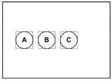
- the input control unit 9 displays a rectangular instruction region surrounding the buttons A, B, and C.
- a control signal corresponding to the coordinate position is output to the external device. For example, if the coordinate position is that of the button A, a control signal indicating that the button A is instructed is output to the external device.
- the input control unit 9 also controls each unit constituting the device 1.
- the range setting unit 10 changes the control range on the input unit 3 in accordance with the display mode switching by the display switching unit 8.
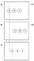
- FIG. 3 is a diagram for explaining the change of the control range.
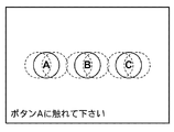
- the instruction image is three-dimensionally displayed using two images including three buttons.
- the two images G1 and G2 include three buttons A, B, and C, respectively.
- the horizontal positions of the three buttons A, B, and C between the images G1 and G2 have parallax so that they can be stereoscopically viewed when three-dimensional display is performed as described later.
- the range setting unit 10 displays the image G1 in the input unit 3.
- An area corresponding to each of the buttons A, B, and C is set as a control range.
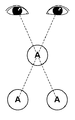
- FIG. 4 shows a state where the button A is stereoscopically viewed.
- the positions where the buttons A, B, and C are visually recognized by the stereoscopic view are substantially intermediate positions in the horizontal direction of the buttons A, B, and C in the images G1 and G2.
- the range setting unit 10 sets the intermediate position of each of the buttons A, B, and C of the images G1 and G2 as the control range, as indicated by a broken line in c in FIG.
- the storage unit 11 stores data representing the control range of the input unit 3.
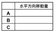
- FIG. 5 is a diagram showing data representing the control range.
- the data representing the control range is that the image G1 is used as an instruction image during two-dimensional display, so that the buttons A, B, and C included in the image G1 are horizontal on the image G1. Contains the coordinates of the start and end positions in the direction and the vertical direction. Note that the size of the control range may be used instead of the end position.
- the storage unit 11 also stores data representing a control range when the instruction image is three-dimensionally displayed. Data representing the control range during the three-dimensional display is calculated from data representing the control range of the images G1 and G2.
- the control range during the three-dimensional display of the instruction image is obtained by moving the control range of the image G1 in the horizontal direction, and the amount of movement is the horizontal direction of each of the buttons A, B, and C in the images G1 and G2. This is a value obtained by halving the difference value of the position of.
- the horizontal movement amount with respect to C may be stored. Thereby, the data amount of the data showing the control range memorize
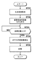
- FIG. 7 is a flowchart showing processing performed in the first embodiment.
- the input control unit 9 determines whether or not the display unit 2 has been switched to three-dimensional display by the display switching unit 8 (step ST1). If step ST1 is affirmed, the three-dimensional processing unit 7 performs three-dimensional processing on the images G1 and G2, and generates an instruction image for three-dimensional display (step ST2).
- the range setting unit 10 switches the control range on the input unit 3 for 3D display (step ST3), and the display control unit 5 displays the 3D display instruction image on the display unit 2 in 3D (step ST4). ), The process is terminated.
- buttons A, B, and C included in the instruction image displayed three-dimensionally on the display unit 2 are stereoscopically matched with the control range on the input unit 3, the user can By touching the input unit 3 so as to touch the viewed buttons A, B, and C, an instruction intended by the user can be input to the device 1.
- step ST1 when step ST1 is denied, the range setting unit 10 switches the control range on the input unit 3 to two-dimensional display (step ST5), and the display control unit 5 displays the instruction image on the display unit 2 two-dimensionally. (Step ST6), the process ends.
- the position of the control range corresponding to the buttons A, B, and C is changed depending on whether the instruction image is displayed two-dimensionally or three-dimensionally. Can be set in the control range at a position corresponding to the position at which the buttons A, B, and C are viewed in stereoscopic view. Therefore, it is possible to accurately detect the indicated position on the screen on which the three-dimensional display is performed.
- FIG. 8 is a schematic block diagram showing a configuration of an instruction input device to which an instruction position setting device according to the second embodiment of the present invention is applied.
- the same components as those in the first embodiment are denoted by the same reference numerals, and detailed description thereof is omitted here.
- the input instruction device 1A includes a biometric information registration unit 14 that registers biometric information such as a user's fingerprint, iris, palm, and face, and a control range at the time of three-dimensional display according to the user.
- a range registration unit 15 for registration is provided.
- the biometric information registration unit 14 includes an imaging unit for imaging the user's biometric information, and acquires biometric information by imaging the user's fingerprint, iris, palm, face, and the like.
- FIG. 9 is a flowchart showing processing performed in the second embodiment. Only the process of registering the control range will be described here. Further, it is assumed that two images for range registration are input to the apparatus 1, and a three-dimensional display image for range registration is also generated from the two images.
- the biometric information registration unit 14 acquires the biometric information of the user (step ST21), and the display control unit 5 displays the range registration image on the display unit 2 three-dimensionally (step ST22).
- FIG. 10 is a diagram showing a range registration image displayed three-dimensionally in the second embodiment.
- buttons A, B, and C indicated by broken lines indicate the positions of the buttons A, B, and C included in the range registration image, and the positions where the buttons A, B, and C indicated by solid lines are stereoscopically displayed. Indicates.
- the text “Register button A” is included in the range registration image.
- the input unit 3 When the user views the range registration image and touches the button A, the input unit 3 outputs information on the coordinate position indicating the temporary designated position touched by the user, and the input coordinate acquisition unit 4 sends the coordinate position to the input control unit 9. The information of is output. For this reason, the input control unit 9 starts monitoring whether or not the coordinate position information is input (step ST23), and when step ST23 is affirmed, outputs the coordinate position information to the range registration unit 15, When the registration unit 15 performs the three-dimensional display with respect to the position of the instruction area during the two-dimensional display, based on the input coordinate position information and the coordinate position information of the button A of one of the two images. The amount of horizontal movement of the temporary designated position on the display unit 2 is calculated (step ST24). Then, the biometric information and the horizontal movement amount are associated with each other and stored in the storage unit 11 (step ST25), and the process ends.
- FIG. 11 is a diagram illustrating data representing a control range stored in the storage unit 11 in the second embodiment.
- the data representing the control range in the second embodiment is, for example, the biometric information of three users U1 to U3 and the positions of buttons A, B, and C of one image at the time of three-dimensional display.
- the horizontal movement amount of the temporary designated position on the display unit 2 is associated with the temporary designated position.
- the user's biological information is read from the biological information registration unit 14.
- the position of the control range can be set according to the stereoscopic effect of the user. As a result, the indicated position can be detected more accurately.
- the user's biological information and the horizontal movement amount are associated with each other.
- the user ID and the horizontal movement amount may be associated with each other.
- a character input device such as a keyboard may be provided in the device 1A, and a user ID may be input from the character input device.
- the pointing position setting device in the first and second embodiments is used for setting an aim in a shooting game in which a laser beam emitted from a laser gun is applied to the aim displayed on the display unit 2 to compete for points. It is also possible. In this case, the position of the control range corresponding to the aim is set at the start of the game using the input unit 3 that optically detects the indicated position, and the laser beam on the screen is set based on the set position of the control range. What is necessary is just to detect the position which hit.
- the horizontal movement amount for the set control range position is stored in the storage unit 11, and the position of the control range corresponding to the aim is determined based on the stored horizontal movement amount at the start of the next game. You may make it set.
- the ID of the laser gun used in the game and the horizontal movement amount are stored in the storage unit 11 in association with each other, and the horizontal movement corresponding to the ID information is input by inputting the ID information of the laser gun. The amount may be read out.
- the ID of the laser gun used by each person and the amount of horizontal movement are stored in the storage unit 11 in correspondence with each other according to the ID information of the laser gun.
- the position of the control range corresponding to the aim may be set for each person based on the horizontal movement amount.
- the computer includes the input coordinate acquisition unit 4, the display control unit 5, the three-dimensional processing unit 7, the display switching unit 8, the input control unit 9, and the range setting unit. 10.
- a program that functions as means corresponding to the biometric information registering unit 14 and the range registering unit 15 and performs processing as shown in FIGS. 7 and 9 is also one embodiment of the present invention.
- a computer-readable recording medium in which such a program is recorded is also one embodiment of the present invention.
- FIG. 1 is a schematic block diagram showing a configuration of an instruction input device to which an instruction position setting device according to a first embodiment of the present invention is applied.
- the schematic block diagram which shows the structure of the instruction
Landscapes
- Engineering & Computer Science (AREA)
- General Engineering & Computer Science (AREA)
- Theoretical Computer Science (AREA)
- Human Computer Interaction (AREA)
- Physics & Mathematics (AREA)
- General Physics & Mathematics (AREA)
- User Interface Of Digital Computer (AREA)
- Testing, Inspecting, Measuring Of Stereoscopic Televisions And Televisions (AREA)
- Processing Or Creating Images (AREA)
- Position Input By Displaying (AREA)
Priority Applications (4)
| Application Number | Priority Date | Filing Date | Title |
|---|---|---|---|
| EP09809543A EP2339435A4 (en) | 2008-08-27 | 2009-08-26 | DEVICE AND METHOD FOR SETTING THE INSTRUCTION POSITION DURING A THREE-DIMENSIONAL DISPLAY AND PROGRAM |
| US13/061,199 US8482557B2 (en) | 2008-08-27 | 2009-08-26 | Device and method for setting instructed position during three-dimensional display, as well as program |
| BRPI0916900A BRPI0916900A2 (pt) | 2008-08-27 | 2009-08-26 | dispositivo e método para definir a posicao instruída durante uma exibição tridimensional, e programa |
| CN2009801334666A CN102132236A (zh) | 2008-08-27 | 2009-08-26 | 用于在三维显示期间设置指示位置的装置和方法及程序 |
Applications Claiming Priority (2)
| Application Number | Priority Date | Filing Date | Title |
|---|---|---|---|
| JP2008-218056 | 2008-08-27 | ||
| JP2008218056A JP4657331B2 (ja) | 2008-08-27 | 2008-08-27 | 3次元表示時における指示位置設定装置および方法並びにプログラム |
Publications (1)
| Publication Number | Publication Date |
|---|---|
| WO2010023887A1 true WO2010023887A1 (ja) | 2010-03-04 |
Family
ID=41721070
Family Applications (1)
| Application Number | Title | Priority Date | Filing Date |
|---|---|---|---|
| PCT/JP2009/004111 WO2010023887A1 (ja) | 2008-08-27 | 2009-08-26 | 3次元表示時における指示位置設定装置および方法並びにプログラム |
Country Status (7)
Cited By (7)
| Publication number | Priority date | Publication date | Assignee | Title |
|---|---|---|---|---|
| CN102346642A (zh) * | 2010-07-29 | 2012-02-08 | Lg电子株式会社 | 移动终端和控制移动终端的操作的方法 |
| CN102591505A (zh) * | 2011-01-12 | 2012-07-18 | 纬创资通股份有限公司 | 电子装置及其触碰位置的校正方法 |
| CN102812420A (zh) * | 2010-03-18 | 2012-12-05 | 富士胶片株式会社 | 立体显示装置和立体成像装置、用于上述装置的优势眼判定方法和优势眼判定程序以及记录介质 |
| CN103477646A (zh) * | 2011-04-20 | 2013-12-25 | 皇家飞利浦有限公司 | 用于3d显示的位置指示器 |
| EP2716052A1 (en) * | 2011-05-23 | 2014-04-09 | Qualcomm Incorporated | Interactive user interface for stereoscopic effect adjustment |
| EP2608047A4 (en) * | 2010-08-16 | 2014-04-30 | Rakuten Inc | INTERNET MANAGEMENT DEVICE, INTERNET MANAGEMENT PROCESS, INTERNET MANAGEMENT PROGRAM, COMPUTER READABLE RECORDING MEDIA FOR RECORDING THE PROGRAM AND INTERNET SYSTEM |
| US9086742B2 (en) | 2010-06-29 | 2015-07-21 | Fujifilm Corporation | Three-dimensional display device, three-dimensional image capturing device, and pointing determination method |
Families Citing this family (11)
| Publication number | Priority date | Publication date | Assignee | Title |
|---|---|---|---|---|
| CN102812419A (zh) * | 2010-03-18 | 2012-12-05 | 富士胶片株式会社 | 立体图像显示设备及其控制方法 |
| JP5766479B2 (ja) * | 2011-03-25 | 2015-08-19 | 京セラ株式会社 | 電子機器、制御方法および制御プログラム |
| JP5693708B2 (ja) | 2011-03-31 | 2015-04-01 | 富士フイルム株式会社 | 立体表示装置、指示受付方法及びプログラムならびにその記録媒体 |
| US20140089859A1 (en) | 2011-05-24 | 2014-03-27 | Mitsubishi Electric Corporation | Equipment control device, operation reception method, and program |
| JP5367020B2 (ja) * | 2011-06-24 | 2013-12-11 | 株式会社ソニー・コンピュータエンタテインメント | 情報処理装置、情報処理方法、プログラム及び情報記憶媒体 |
| JP5989315B2 (ja) * | 2011-09-22 | 2016-09-07 | 任天堂株式会社 | 表示制御プログラム、表示制御システム、表示制御装置、および、表示制御方法 |
| KR20140097226A (ko) * | 2011-11-21 | 2014-08-06 | 가부시키가이샤 니콘 | 표시장치, 표시 제어 프로그램 |
| WO2013118328A1 (ja) * | 2012-02-07 | 2013-08-15 | オリンパス株式会社 | 表示装置、電子機器及び表示装置用プログラム |
| CN103809782B (zh) * | 2012-11-05 | 2016-11-23 | 宏碁股份有限公司 | 触碰位置补偿方法及装置 |
| CN105376559B (zh) * | 2015-11-05 | 2019-03-12 | 广东未来科技有限公司 | 立体显示装置及其视点校正方法 |
| CN109979017A (zh) * | 2019-04-08 | 2019-07-05 | 王黎明 | 基于视角转换的指路装置及方法 |
Citations (5)
| Publication number | Priority date | Publication date | Assignee | Title |
|---|---|---|---|---|
| JPH06309102A (ja) * | 1993-04-01 | 1994-11-04 | Internatl Business Mach Corp <Ibm> | タッチ・スクリーン装置および感知領域の動的調整方法 |
| JPH10105735A (ja) * | 1996-09-30 | 1998-04-24 | Terumo Corp | 入力装置及び画像表示システム |
| JP2004151513A (ja) | 2002-10-31 | 2004-05-27 | Pioneer Electronic Corp | 表示装置及び方法 |
| JP2004280496A (ja) * | 2003-03-17 | 2004-10-07 | Kyocera Mita Corp | 操作パネル装置 |
| US20060161870A1 (en) | 2004-07-30 | 2006-07-20 | Apple Computer, Inc. | Proximity detector in handheld device |
Family Cites Families (18)
| Publication number | Priority date | Publication date | Assignee | Title |
|---|---|---|---|---|
| JP3143278B2 (ja) * | 1993-08-18 | 2001-03-07 | 富士通株式会社 | 組立図作成方法及び装置 |
| JPH10340159A (ja) * | 1997-06-06 | 1998-12-22 | Canon Inc | 情報処理装置及び方法及びコンピュータ可読メモリ |
| JP3655433B2 (ja) * | 1997-06-20 | 2005-06-02 | パイオニア株式会社 | コンピュータ読み取り可能な記録媒体及び情報再生装置 |
| US6055103A (en) * | 1997-06-28 | 2000-04-25 | Sharp Kabushiki Kaisha | Passive polarisation modulating optical element and method of making such an element |
| JP2000056929A (ja) * | 1998-08-11 | 2000-02-25 | Amada Eng Center Co Ltd | 表示式入力装置の視差補正方法およびその装置 |
| DE69924231T2 (de) * | 1999-03-29 | 2006-02-16 | Matsushita Electric Industrial Co., Ltd., Kadoma | Antriebsvorrichtung für einen Schrittmotor |
| JP2002287907A (ja) * | 2001-03-23 | 2002-10-04 | Ricoh Co Ltd | タッチパネル入力装置及び入力方法 |
| US8369607B2 (en) * | 2002-03-27 | 2013-02-05 | Sanyo Electric Co., Ltd. | Method and apparatus for processing three-dimensional images |
| EP2357836B1 (en) | 2002-03-27 | 2015-05-13 | Sanyo Electric Co., Ltd. | Method and apparatus for processing three-dimensional images |
| JP2004362218A (ja) * | 2003-06-04 | 2004-12-24 | Canon Inc | 三次元物体操作方法 |
| US7477775B2 (en) * | 2003-07-18 | 2009-01-13 | Olympus Corporation | Microscope system |
| JP4523368B2 (ja) * | 2004-09-10 | 2010-08-11 | 株式会社マーキュリーシステム | 立体視画像生成装置およびプログラム |
| JP2006186589A (ja) * | 2004-12-27 | 2006-07-13 | Olympus Imaging Corp | 表示制御装置及び表示制御方法 |
| EP1958043A1 (en) * | 2005-11-30 | 2008-08-20 | Koninklijke Philips Electronics N.V. | Light pen input system and method, particularly for use with large area non-crt displays |
| WO2008062586A1 (fr) | 2006-11-22 | 2008-05-29 | Sharp Kabushiki Kaisha | Dispositif d'affichage, procédé d'affichage, programme d'affichage, et support d'enregistrement |
| US8494227B2 (en) * | 2007-04-17 | 2013-07-23 | Francine J. Prokoski | System and method for using three dimensional infrared imaging to identify individuals |
| US7801271B2 (en) * | 2007-12-23 | 2010-09-21 | Oraya Therapeutics, Inc. | Methods and devices for orthovoltage ocular radiotherapy and treatment planning |
| WO2010009447A2 (en) * | 2008-07-18 | 2010-01-21 | Doheny Eye Institute | Optical coherence tomography - based ophthalmic testing methods, devices and systems |
-
2008
- 2008-08-27 JP JP2008218056A patent/JP4657331B2/ja not_active Expired - Fee Related
-
2009
- 2009-08-26 BR BRPI0916900A patent/BRPI0916900A2/pt not_active IP Right Cessation
- 2009-08-26 CN CN2009801334666A patent/CN102132236A/zh active Pending
- 2009-08-26 KR KR1020117004440A patent/KR20110053436A/ko not_active Abandoned
- 2009-08-26 WO PCT/JP2009/004111 patent/WO2010023887A1/ja active Application Filing
- 2009-08-26 US US13/061,199 patent/US8482557B2/en not_active Expired - Fee Related
- 2009-08-26 EP EP09809543A patent/EP2339435A4/en not_active Withdrawn
Patent Citations (5)
| Publication number | Priority date | Publication date | Assignee | Title |
|---|---|---|---|---|
| JPH06309102A (ja) * | 1993-04-01 | 1994-11-04 | Internatl Business Mach Corp <Ibm> | タッチ・スクリーン装置および感知領域の動的調整方法 |
| JPH10105735A (ja) * | 1996-09-30 | 1998-04-24 | Terumo Corp | 入力装置及び画像表示システム |
| JP2004151513A (ja) | 2002-10-31 | 2004-05-27 | Pioneer Electronic Corp | 表示装置及び方法 |
| JP2004280496A (ja) * | 2003-03-17 | 2004-10-07 | Kyocera Mita Corp | 操作パネル装置 |
| US20060161870A1 (en) | 2004-07-30 | 2006-07-20 | Apple Computer, Inc. | Proximity detector in handheld device |
Non-Patent Citations (1)
| Title |
|---|
| See also references of EP2339435A4 |
Cited By (14)
| Publication number | Priority date | Publication date | Assignee | Title |
|---|---|---|---|---|
| CN102812420A (zh) * | 2010-03-18 | 2012-12-05 | 富士胶片株式会社 | 立体显示装置和立体成像装置、用于上述装置的优势眼判定方法和优势眼判定程序以及记录介质 |
| US9086742B2 (en) | 2010-06-29 | 2015-07-21 | Fujifilm Corporation | Three-dimensional display device, three-dimensional image capturing device, and pointing determination method |
| US8878822B2 (en) | 2010-07-29 | 2014-11-04 | Lg Electronics Inc. | Mobile terminal and method of controlling operation of the mobile terminal |
| EP2413225A3 (en) * | 2010-07-29 | 2012-12-19 | Lg Electronics Inc. | Mobile terminal with 3D display and method of controlling operation of the mobile terminal |
| CN102346642A (zh) * | 2010-07-29 | 2012-02-08 | Lg电子株式会社 | 移动终端和控制移动终端的操作的方法 |
| KR20120032062A (ko) * | 2010-07-29 | 2012-04-05 | 엘지전자 주식회사 | 휴대 단말기 및 그 동작 제어방법 |
| KR101709497B1 (ko) * | 2010-07-29 | 2017-02-23 | 엘지전자 주식회사 | 휴대 단말기 및 그 동작 제어방법 |
| EP2608047A4 (en) * | 2010-08-16 | 2014-04-30 | Rakuten Inc | INTERNET MANAGEMENT DEVICE, INTERNET MANAGEMENT PROCESS, INTERNET MANAGEMENT PROGRAM, COMPUTER READABLE RECORDING MEDIA FOR RECORDING THE PROGRAM AND INTERNET SYSTEM |
| CN102591505A (zh) * | 2011-01-12 | 2012-07-18 | 纬创资通股份有限公司 | 电子装置及其触碰位置的校正方法 |
| TWI461975B (zh) * | 2011-01-12 | 2014-11-21 | Wistron Corp | 電子裝置及其觸碰位置之校正方法 |
| CN103477646A (zh) * | 2011-04-20 | 2013-12-25 | 皇家飞利浦有限公司 | 用于3d显示的位置指示器 |
| EP2716052A1 (en) * | 2011-05-23 | 2014-04-09 | Qualcomm Incorporated | Interactive user interface for stereoscopic effect adjustment |
| JP2014517619A (ja) * | 2011-05-23 | 2014-07-17 | クゥアルコム・インコーポレイテッド | 立体視効果の調整用の対話型ユーザインターフェース |
| JP2016192773A (ja) * | 2011-05-23 | 2016-11-10 | クゥアルコム・インコーポレイテッドQualcomm Incorporated | 立体視効果の調整用の対話型ユーザインターフェース |
Also Published As
| Publication number | Publication date |
|---|---|
| KR20110053436A (ko) | 2011-05-23 |
| US20110141108A1 (en) | 2011-06-16 |
| BRPI0916900A2 (pt) | 2015-11-24 |
| CN102132236A (zh) | 2011-07-20 |
| US8482557B2 (en) | 2013-07-09 |
| JP2010055266A (ja) | 2010-03-11 |
| EP2339435A1 (en) | 2011-06-29 |
| JP4657331B2 (ja) | 2011-03-23 |
| EP2339435A4 (en) | 2012-06-06 |
Similar Documents
| Publication | Publication Date | Title |
|---|---|---|
| JP4657331B2 (ja) | 3次元表示時における指示位置設定装置および方法並びにプログラム | |
| JP5450791B2 (ja) | 立体表示装置及び立体撮影装置、並びに利き目判定方法及びこれに用いる利き目判定プログラム並びに記録媒体 | |
| US8243125B2 (en) | Image display device | |
| JP5295714B2 (ja) | 表示装置、画像処理方法、及びコンピュータプログラム | |
| JP5300825B2 (ja) | 指示受付装置、指示受付方法、コンピュータプログラム及び記録媒体 | |
| US9693039B2 (en) | Hand-held electronic device | |
| JP6064316B2 (ja) | 透過型表示装置、及び操作入力方法 | |
| US20120056989A1 (en) | Image recognition apparatus, operation determining method and program | |
| JP5029759B2 (ja) | 情報入力システム | |
| CN102300110A (zh) | 显示设备 | |
| JP5693708B2 (ja) | 立体表示装置、指示受付方法及びプログラムならびにその記録媒体 | |
| JP2012090256A (ja) | 画像表示装置及び撮像装置 | |
| JP5857082B2 (ja) | 表示装置及び電子機器 | |
| JP2010107685A (ja) | 3次元表示装置および方法並びにプログラム | |
| JP4870651B2 (ja) | 情報入力システムおよび情報入力方法 | |
| JP5730086B2 (ja) | 入力装置および入力方法 | |
| JP5140719B2 (ja) | 3次元表示時における指示位置設定装置および方法並びにプログラム | |
| JP2013145323A (ja) | カメラ付きミラー装置、ミラー付き什器 | |
| KR20140003107A (ko) | 증강 현실 표현 장치 및 방법 | |
| JP2014048565A (ja) | 画像表示装置 | |
| JP2014233005A (ja) | 画像表示装置 | |
| CN105785749B (zh) | 一种显示方法及电子设备 | |
| JP2024097269A (ja) | 情報処理装置および情報処理方法 | |
| JP2006042280A (ja) | 画像処理装置 | |
| TW201201042A (en) | Display system and suggestion system |
Legal Events
| Date | Code | Title | Description |
|---|---|---|---|
| WWE | Wipo information: entry into national phase |
Ref document number: 200980133466.6 Country of ref document: CN |
|
| 121 | Ep: the epo has been informed by wipo that ep was designated in this application |
Ref document number: 09809543 Country of ref document: EP Kind code of ref document: A1 |
|
| ENP | Entry into the national phase |
Ref document number: 20117004440 Country of ref document: KR Kind code of ref document: A |
|
| WWE | Wipo information: entry into national phase |
Ref document number: 13061199 Country of ref document: US |
|
| NENP | Non-entry into the national phase |
Ref country code: DE |
|
| WWE | Wipo information: entry into national phase |
Ref document number: 900/KOLNP/2011 Country of ref document: IN |
|
| WWE | Wipo information: entry into national phase |
Ref document number: 2009809543 Country of ref document: EP |
|
| WWE | Wipo information: entry into national phase |
Ref document number: 13061199 Country of ref document: US |
|
| ENP | Entry into the national phase |
Ref document number: PI0916900 Country of ref document: BR Kind code of ref document: A2 Effective date: 20110222 |