WO2010013652A1 - 省燃費運転診断装置、車載システム、駆動制御装置および省燃費運転診断プログラム - Google Patents
省燃費運転診断装置、車載システム、駆動制御装置および省燃費運転診断プログラム Download PDFInfo
- Publication number
- WO2010013652A1 WO2010013652A1 PCT/JP2009/063269 JP2009063269W WO2010013652A1 WO 2010013652 A1 WO2010013652 A1 WO 2010013652A1 JP 2009063269 W JP2009063269 W JP 2009063269W WO 2010013652 A1 WO2010013652 A1 WO 2010013652A1
- Authority
- WO
- WIPO (PCT)
- Prior art keywords
- electric energy
- fuel
- driving
- vehicle
- power amount
- Prior art date
- Legal status (The legal status is an assumption and is not a legal conclusion. Google has not performed a legal analysis and makes no representation as to the accuracy of the status listed.)
- Ceased
Links
Images

Classifications
-
- B—PERFORMING OPERATIONS; TRANSPORTING
- B60—VEHICLES IN GENERAL
- B60W—CONJOINT CONTROL OF VEHICLE SUB-UNITS OF DIFFERENT TYPE OR DIFFERENT FUNCTION; CONTROL SYSTEMS SPECIALLY ADAPTED FOR HYBRID VEHICLES; ROAD VEHICLE DRIVE CONTROL SYSTEMS FOR PURPOSES NOT RELATED TO THE CONTROL OF A PARTICULAR SUB-UNIT
- B60W50/00—Details of control systems for road vehicle drive control not related to the control of a particular sub-unit, e.g. process diagnostic or vehicle driver interfaces
- B60W50/04—Monitoring the functioning of the control system
-
- B—PERFORMING OPERATIONS; TRANSPORTING
- B60—VEHICLES IN GENERAL
- B60L—PROPULSION OF ELECTRICALLY-PROPELLED VEHICLES; SUPPLYING ELECTRIC POWER FOR AUXILIARY EQUIPMENT OF ELECTRICALLY-PROPELLED VEHICLES; ELECTRODYNAMIC BRAKE SYSTEMS FOR VEHICLES IN GENERAL; MAGNETIC SUSPENSION OR LEVITATION FOR VEHICLES; MONITORING OPERATING VARIABLES OF ELECTRICALLY-PROPELLED VEHICLES; ELECTRIC SAFETY DEVICES FOR ELECTRICALLY-PROPELLED VEHICLES
- B60L15/00—Methods, circuits, or devices for controlling the traction-motor speed of electrically-propelled vehicles
- B60L15/20—Methods, circuits, or devices for controlling the traction-motor speed of electrically-propelled vehicles for control of the vehicle or its driving motor to achieve a desired performance, e.g. speed, torque, programmed variation of speed
- B60L15/2045—Methods, circuits, or devices for controlling the traction-motor speed of electrically-propelled vehicles for control of the vehicle or its driving motor to achieve a desired performance, e.g. speed, torque, programmed variation of speed for optimising the use of energy
-
- B—PERFORMING OPERATIONS; TRANSPORTING
- B60—VEHICLES IN GENERAL
- B60L—PROPULSION OF ELECTRICALLY-PROPELLED VEHICLES; SUPPLYING ELECTRIC POWER FOR AUXILIARY EQUIPMENT OF ELECTRICALLY-PROPELLED VEHICLES; ELECTRODYNAMIC BRAKE SYSTEMS FOR VEHICLES IN GENERAL; MAGNETIC SUSPENSION OR LEVITATION FOR VEHICLES; MONITORING OPERATING VARIABLES OF ELECTRICALLY-PROPELLED VEHICLES; ELECTRIC SAFETY DEVICES FOR ELECTRICALLY-PROPELLED VEHICLES
- B60L53/00—Methods of charging batteries, specially adapted for electric vehicles; Charging stations or on-board charging equipment therefor; Exchange of energy storage elements in electric vehicles
- B60L53/60—Monitoring or controlling charging stations
- B60L53/64—Optimising energy costs, e.g. responding to electricity rates
-
- B—PERFORMING OPERATIONS; TRANSPORTING
- B60—VEHICLES IN GENERAL
- B60W—CONJOINT CONTROL OF VEHICLE SUB-UNITS OF DIFFERENT TYPE OR DIFFERENT FUNCTION; CONTROL SYSTEMS SPECIALLY ADAPTED FOR HYBRID VEHICLES; ROAD VEHICLE DRIVE CONTROL SYSTEMS FOR PURPOSES NOT RELATED TO THE CONTROL OF A PARTICULAR SUB-UNIT
- B60W10/00—Conjoint control of vehicle sub-units of different type or different function
- B60W10/04—Conjoint control of vehicle sub-units of different type or different function including control of propulsion units
- B60W10/08—Conjoint control of vehicle sub-units of different type or different function including control of propulsion units including control of electric propulsion units, e.g. motors or generators
-
- B—PERFORMING OPERATIONS; TRANSPORTING
- B60—VEHICLES IN GENERAL
- B60W—CONJOINT CONTROL OF VEHICLE SUB-UNITS OF DIFFERENT TYPE OR DIFFERENT FUNCTION; CONTROL SYSTEMS SPECIALLY ADAPTED FOR HYBRID VEHICLES; ROAD VEHICLE DRIVE CONTROL SYSTEMS FOR PURPOSES NOT RELATED TO THE CONTROL OF A PARTICULAR SUB-UNIT
- B60W10/00—Conjoint control of vehicle sub-units of different type or different function
- B60W10/24—Conjoint control of vehicle sub-units of different type or different function including control of energy storage means
-
- B—PERFORMING OPERATIONS; TRANSPORTING
- B60—VEHICLES IN GENERAL
- B60W—CONJOINT CONTROL OF VEHICLE SUB-UNITS OF DIFFERENT TYPE OR DIFFERENT FUNCTION; CONTROL SYSTEMS SPECIALLY ADAPTED FOR HYBRID VEHICLES; ROAD VEHICLE DRIVE CONTROL SYSTEMS FOR PURPOSES NOT RELATED TO THE CONTROL OF A PARTICULAR SUB-UNIT
- B60W10/00—Conjoint control of vehicle sub-units of different type or different function
- B60W10/24—Conjoint control of vehicle sub-units of different type or different function including control of energy storage means
- B60W10/26—Conjoint control of vehicle sub-units of different type or different function including control of energy storage means for electrical energy, e.g. batteries or capacitors
-
- B—PERFORMING OPERATIONS; TRANSPORTING
- B60—VEHICLES IN GENERAL
- B60L—PROPULSION OF ELECTRICALLY-PROPELLED VEHICLES; SUPPLYING ELECTRIC POWER FOR AUXILIARY EQUIPMENT OF ELECTRICALLY-PROPELLED VEHICLES; ELECTRODYNAMIC BRAKE SYSTEMS FOR VEHICLES IN GENERAL; MAGNETIC SUSPENSION OR LEVITATION FOR VEHICLES; MONITORING OPERATING VARIABLES OF ELECTRICALLY-PROPELLED VEHICLES; ELECTRIC SAFETY DEVICES FOR ELECTRICALLY-PROPELLED VEHICLES
- B60L2240/00—Control parameters of input or output; Target parameters
- B60L2240/60—Navigation input
-
- B—PERFORMING OPERATIONS; TRANSPORTING
- B60—VEHICLES IN GENERAL
- B60W—CONJOINT CONTROL OF VEHICLE SUB-UNITS OF DIFFERENT TYPE OR DIFFERENT FUNCTION; CONTROL SYSTEMS SPECIALLY ADAPTED FOR HYBRID VEHICLES; ROAD VEHICLE DRIVE CONTROL SYSTEMS FOR PURPOSES NOT RELATED TO THE CONTROL OF A PARTICULAR SUB-UNIT
- B60W20/00—Control systems specially adapted for hybrid vehicles
-
- B—PERFORMING OPERATIONS; TRANSPORTING
- B60—VEHICLES IN GENERAL
- B60W—CONJOINT CONTROL OF VEHICLE SUB-UNITS OF DIFFERENT TYPE OR DIFFERENT FUNCTION; CONTROL SYSTEMS SPECIALLY ADAPTED FOR HYBRID VEHICLES; ROAD VEHICLE DRIVE CONTROL SYSTEMS FOR PURPOSES NOT RELATED TO THE CONTROL OF A PARTICULAR SUB-UNIT
- B60W2510/00—Input parameters relating to a particular sub-units
- B60W2510/24—Energy storage means
- B60W2510/242—Energy storage means for electrical energy
- B60W2510/244—Charge state
-
- B—PERFORMING OPERATIONS; TRANSPORTING
- B60—VEHICLES IN GENERAL
- B60W—CONJOINT CONTROL OF VEHICLE SUB-UNITS OF DIFFERENT TYPE OR DIFFERENT FUNCTION; CONTROL SYSTEMS SPECIALLY ADAPTED FOR HYBRID VEHICLES; ROAD VEHICLE DRIVE CONTROL SYSTEMS FOR PURPOSES NOT RELATED TO THE CONTROL OF A PARTICULAR SUB-UNIT
- B60W2710/00—Output or target parameters relating to a particular sub-units
- B60W2710/24—Energy storage means
- B60W2710/242—Energy storage means for electrical energy
-
- B—PERFORMING OPERATIONS; TRANSPORTING
- B60—VEHICLES IN GENERAL
- B60W—CONJOINT CONTROL OF VEHICLE SUB-UNITS OF DIFFERENT TYPE OR DIFFERENT FUNCTION; CONTROL SYSTEMS SPECIALLY ADAPTED FOR HYBRID VEHICLES; ROAD VEHICLE DRIVE CONTROL SYSTEMS FOR PURPOSES NOT RELATED TO THE CONTROL OF A PARTICULAR SUB-UNIT
- B60W2720/00—Output or target parameters relating to overall vehicle dynamics
- B60W2720/10—Longitudinal speed
- B60W2720/106—Longitudinal acceleration
-
- Y—GENERAL TAGGING OF NEW TECHNOLOGICAL DEVELOPMENTS; GENERAL TAGGING OF CROSS-SECTIONAL TECHNOLOGIES SPANNING OVER SEVERAL SECTIONS OF THE IPC; TECHNICAL SUBJECTS COVERED BY FORMER USPC CROSS-REFERENCE ART COLLECTIONS [XRACs] AND DIGESTS
- Y02—TECHNOLOGIES OR APPLICATIONS FOR MITIGATION OR ADAPTATION AGAINST CLIMATE CHANGE
- Y02T—CLIMATE CHANGE MITIGATION TECHNOLOGIES RELATED TO TRANSPORTATION
- Y02T10/00—Road transport of goods or passengers
- Y02T10/60—Other road transportation technologies with climate change mitigation effect
- Y02T10/62—Hybrid vehicles
-
- Y—GENERAL TAGGING OF NEW TECHNOLOGICAL DEVELOPMENTS; GENERAL TAGGING OF CROSS-SECTIONAL TECHNOLOGIES SPANNING OVER SEVERAL SECTIONS OF THE IPC; TECHNICAL SUBJECTS COVERED BY FORMER USPC CROSS-REFERENCE ART COLLECTIONS [XRACs] AND DIGESTS
- Y02—TECHNOLOGIES OR APPLICATIONS FOR MITIGATION OR ADAPTATION AGAINST CLIMATE CHANGE
- Y02T—CLIMATE CHANGE MITIGATION TECHNOLOGIES RELATED TO TRANSPORTATION
- Y02T10/00—Road transport of goods or passengers
- Y02T10/60—Other road transportation technologies with climate change mitigation effect
- Y02T10/64—Electric machine technologies in electromobility
-
- Y—GENERAL TAGGING OF NEW TECHNOLOGICAL DEVELOPMENTS; GENERAL TAGGING OF CROSS-SECTIONAL TECHNOLOGIES SPANNING OVER SEVERAL SECTIONS OF THE IPC; TECHNICAL SUBJECTS COVERED BY FORMER USPC CROSS-REFERENCE ART COLLECTIONS [XRACs] AND DIGESTS
- Y02—TECHNOLOGIES OR APPLICATIONS FOR MITIGATION OR ADAPTATION AGAINST CLIMATE CHANGE
- Y02T—CLIMATE CHANGE MITIGATION TECHNOLOGIES RELATED TO TRANSPORTATION
- Y02T10/00—Road transport of goods or passengers
- Y02T10/60—Other road transportation technologies with climate change mitigation effect
- Y02T10/70—Energy storage systems for electromobility, e.g. batteries
-
- Y—GENERAL TAGGING OF NEW TECHNOLOGICAL DEVELOPMENTS; GENERAL TAGGING OF CROSS-SECTIONAL TECHNOLOGIES SPANNING OVER SEVERAL SECTIONS OF THE IPC; TECHNICAL SUBJECTS COVERED BY FORMER USPC CROSS-REFERENCE ART COLLECTIONS [XRACs] AND DIGESTS
- Y02—TECHNOLOGIES OR APPLICATIONS FOR MITIGATION OR ADAPTATION AGAINST CLIMATE CHANGE
- Y02T—CLIMATE CHANGE MITIGATION TECHNOLOGIES RELATED TO TRANSPORTATION
- Y02T10/00—Road transport of goods or passengers
- Y02T10/60—Other road transportation technologies with climate change mitigation effect
- Y02T10/7072—Electromobility specific charging systems or methods for batteries, ultracapacitors, supercapacitors or double-layer capacitors
-
- Y—GENERAL TAGGING OF NEW TECHNOLOGICAL DEVELOPMENTS; GENERAL TAGGING OF CROSS-SECTIONAL TECHNOLOGIES SPANNING OVER SEVERAL SECTIONS OF THE IPC; TECHNICAL SUBJECTS COVERED BY FORMER USPC CROSS-REFERENCE ART COLLECTIONS [XRACs] AND DIGESTS
- Y02—TECHNOLOGIES OR APPLICATIONS FOR MITIGATION OR ADAPTATION AGAINST CLIMATE CHANGE
- Y02T—CLIMATE CHANGE MITIGATION TECHNOLOGIES RELATED TO TRANSPORTATION
- Y02T10/00—Road transport of goods or passengers
- Y02T10/60—Other road transportation technologies with climate change mitigation effect
- Y02T10/72—Electric energy management in electromobility
-
- Y—GENERAL TAGGING OF NEW TECHNOLOGICAL DEVELOPMENTS; GENERAL TAGGING OF CROSS-SECTIONAL TECHNOLOGIES SPANNING OVER SEVERAL SECTIONS OF THE IPC; TECHNICAL SUBJECTS COVERED BY FORMER USPC CROSS-REFERENCE ART COLLECTIONS [XRACs] AND DIGESTS
- Y02—TECHNOLOGIES OR APPLICATIONS FOR MITIGATION OR ADAPTATION AGAINST CLIMATE CHANGE
- Y02T—CLIMATE CHANGE MITIGATION TECHNOLOGIES RELATED TO TRANSPORTATION
- Y02T90/00—Enabling technologies or technologies with a potential or indirect contribution to GHG emissions mitigation
- Y02T90/10—Technologies relating to charging of electric vehicles
- Y02T90/12—Electric charging stations
-
- Y—GENERAL TAGGING OF NEW TECHNOLOGICAL DEVELOPMENTS; GENERAL TAGGING OF CROSS-SECTIONAL TECHNOLOGIES SPANNING OVER SEVERAL SECTIONS OF THE IPC; TECHNICAL SUBJECTS COVERED BY FORMER USPC CROSS-REFERENCE ART COLLECTIONS [XRACs] AND DIGESTS
- Y02—TECHNOLOGIES OR APPLICATIONS FOR MITIGATION OR ADAPTATION AGAINST CLIMATE CHANGE
- Y02T—CLIMATE CHANGE MITIGATION TECHNOLOGIES RELATED TO TRANSPORTATION
- Y02T90/00—Enabling technologies or technologies with a potential or indirect contribution to GHG emissions mitigation
- Y02T90/10—Technologies relating to charging of electric vehicles
- Y02T90/14—Plug-in electric vehicles
-
- Y—GENERAL TAGGING OF NEW TECHNOLOGICAL DEVELOPMENTS; GENERAL TAGGING OF CROSS-SECTIONAL TECHNOLOGIES SPANNING OVER SEVERAL SECTIONS OF THE IPC; TECHNICAL SUBJECTS COVERED BY FORMER USPC CROSS-REFERENCE ART COLLECTIONS [XRACs] AND DIGESTS
- Y02—TECHNOLOGIES OR APPLICATIONS FOR MITIGATION OR ADAPTATION AGAINST CLIMATE CHANGE
- Y02T—CLIMATE CHANGE MITIGATION TECHNOLOGIES RELATED TO TRANSPORTATION
- Y02T90/00—Enabling technologies or technologies with a potential or indirect contribution to GHG emissions mitigation
- Y02T90/10—Technologies relating to charging of electric vehicles
- Y02T90/16—Information or communication technologies improving the operation of electric vehicles
-
- Y—GENERAL TAGGING OF NEW TECHNOLOGICAL DEVELOPMENTS; GENERAL TAGGING OF CROSS-SECTIONAL TECHNOLOGIES SPANNING OVER SEVERAL SECTIONS OF THE IPC; TECHNICAL SUBJECTS COVERED BY FORMER USPC CROSS-REFERENCE ART COLLECTIONS [XRACs] AND DIGESTS
- Y02—TECHNOLOGIES OR APPLICATIONS FOR MITIGATION OR ADAPTATION AGAINST CLIMATE CHANGE
- Y02T—CLIMATE CHANGE MITIGATION TECHNOLOGIES RELATED TO TRANSPORTATION
- Y02T90/00—Enabling technologies or technologies with a potential or indirect contribution to GHG emissions mitigation
- Y02T90/10—Technologies relating to charging of electric vehicles
- Y02T90/16—Information or communication technologies improving the operation of electric vehicles
- Y02T90/167—Systems integrating technologies related to power network operation and communication or information technologies for supporting the interoperability of electric or hybrid vehicles, i.e. smartgrids as interface for battery charging of electric vehicles [EV] or hybrid vehicles [HEV]
-
- Y—GENERAL TAGGING OF NEW TECHNOLOGICAL DEVELOPMENTS; GENERAL TAGGING OF CROSS-SECTIONAL TECHNOLOGIES SPANNING OVER SEVERAL SECTIONS OF THE IPC; TECHNICAL SUBJECTS COVERED BY FORMER USPC CROSS-REFERENCE ART COLLECTIONS [XRACs] AND DIGESTS
- Y04—INFORMATION OR COMMUNICATION TECHNOLOGIES HAVING AN IMPACT ON OTHER TECHNOLOGY AREAS
- Y04S—SYSTEMS INTEGRATING TECHNOLOGIES RELATED TO POWER NETWORK OPERATION, COMMUNICATION OR INFORMATION TECHNOLOGIES FOR IMPROVING THE ELECTRICAL POWER GENERATION, TRANSMISSION, DISTRIBUTION, MANAGEMENT OR USAGE, i.e. SMART GRIDS
- Y04S30/00—Systems supporting specific end-user applications in the sector of transportation
- Y04S30/10—Systems supporting the interoperability of electric or hybrid vehicles
- Y04S30/14—Details associated with the interoperability, e.g. vehicle recognition, authentication, identification or billing
Definitions
- the present invention relates to a fuel-saving driving diagnosis device, a vehicle-mounted system, a drive control device, and a fuel-saving driving diagnosis program for diagnosing a driver's fuel-saving driving in a vehicle driven with electricity as energy.
- the present invention has been made in view of the above, and is a fuel-saving driving diagnostic apparatus capable of calculating information that can sufficiently promote fuel-saving driving for a driver of a plug-in hybrid car.
- An object is to provide an in-vehicle system, a drive control device, and a fuel-saving driving diagnosis program.
- the present invention includes an external power storage unit that stores an external power amount indicating the amount of power charged from an external device, and charging with the power generated by driving the vehicle.
- An internal electric energy storage unit that stores an internal electric energy indicating the generated electric energy; an external electric energy stored in the external electric energy storage unit; an internal electric energy stored in the internal electric energy storage unit;
- a driving power amount calculation unit that calculates a driving power amount indicating the amount of power required for driving by the vehicle from a power amount that the vehicle holds at a local point, and the driving power amount calculated by the driving power amount calculation unit
- a fuel-saving driving diagnosis unit that diagnoses fuel-saving driving based on the external power amount stored in the external power amount storage unit.
- the amount of regenerative power generated by driving the vehicle is also stored, so it is possible to accurately determine how much of the charged power is consumed without using gasoline. Is possible.
- the present invention it is possible to accurately calculate the internal electric energy required only for traveling, and how much the driver uses the internal electric energy only for traveling, that is, the power ratio with respect to the traveling of the driver. Judgment can be made.
- the present invention it is possible to accurately calculate the amount of electric power used in the traveling vehicle, and how much internal electric energy the driver has used while traveling, that is, the power ratio to the driver's use. Can be judged.
- the driver's fuel-saving driving is scored based on the result of diagnosing the driver's fuel-saving driving, it is determined whether or not the driver is fuel-saving driving with easy-to-understand information. can do.
- the driver is notified of fuel-saving driving advice based on the diagnosis result, so that the driver's awareness of fuel-saving driving can be improved. Driving can be further encouraged.
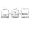
- FIG. 1 is a diagram for explaining the outline of the fuel-saving driving diagnosis device according to the first embodiment.
- FIG. 2 is a block diagram illustrating a configuration of the in-vehicle system including the fuel-saving driving diagnosis device according to the first embodiment.
- FIG. 3 is a diagram illustrating an example of calculating the driving power amount.
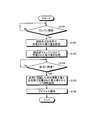
- FIG. 4 is a flowchart illustrating the flow of the fuel-saving driving diagnosis process in the fuel-saving driving diagnosis device according to the first embodiment.
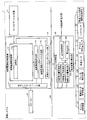
- FIG. 5 is a diagram illustrating an example of an in-vehicle system in which fuel-saving driving diagnosis functions are distributed.
- FIG. 1 is a diagram for explaining the outline of the fuel-saving driving diagnosis device according to the first embodiment.
- a fuel-saving driving diagnosis device 10 according to the first embodiment is a device that is mounted on an in-vehicle system in an electric vehicle such as a plug-in hybrid car, and diagnoses a driver's fuel-saving driving in the vehicle. .
- the in-vehicle system 1 is connected to the fuel-saving driving diagnosis device 10, a speaker 16 that outputs sound in the vehicle, and a car navigation device 17 that provides driving assistance to a driver's seat, etc. It has a fuel-saving driving diagnosis device 10 and an HV traveling control device 20 that performs various controls relating to driving of a vehicle connected via a bus 100.
- the fuel-saving driving diagnosis device 10 illustrated here is merely an example for explaining the present invention, and is not limited thereto.
- various types of vehicles mounted on automobiles such as air conditioners and air purifiers.
- An apparatus may be included.
- Such a fuel-saving driving diagnosis device 10 stores an external power amount indicating the amount of power charged from an external device such as a home, and an internal power amount indicating the amount of power charged by driving the vehicle. Then, the fuel-saving driving diagnosis device 10 drives the driving power indicating the amount of power required for the vehicle to drive from the stored external power amount, the stored internal power amount, and the power amount that the vehicle holds at the local point. The amount is calculated, and the driver's fuel-saving driving is diagnosed based on the calculated driving power amount and the external power amount. As a result, the fuel-saving driving diagnosis device 10 can calculate information that can sufficiently prompt the driver of the plug-in hybrid car to perform fuel-saving driving.
- the fuel-saving driving diagnosis device 10 stores the external electric energy stored in the vehicle as (B + D) and the internal electric energy as (C).
- the fuel-saving driving diagnosis device 10 stores the internal power amount stored when the vehicle holding the above-mentioned power amount leaves the home and returns to the home again. From the external electric energy “B + D” stored as “C” and the electric energy “E” remaining in the vehicle arriving at home, a driving electric energy “D + B + E ⁇ C” indicating the electric energy consumed by the vehicle for driving is obtained. calculate. Subsequently, the fuel-saving driving diagnosis device 10 calculates “external electric energy“ D + B ”/ driving electric energy“ D + B + E ⁇ C ””, and calculates the calculated “(D + B) / (D + B + E ⁇ C)” by the driver. The result is a fuel efficiency driving diagnosis result.
- the fuel-saving driving diagnosis device 10 calculates how much of the electric power used for traveling is consumed by charging from equipment such as home without using gasoline. As a result, it is possible to calculate information that can sufficiently promote fuel-saving driving for the driver of the plug-in hybrid car.
- FIG. 2 is a block diagram illustrating a configuration of the in-vehicle system including the fuel-saving driving diagnosis device according to the first embodiment.
- this in-vehicle system 1 includes a fuel-saving driving diagnosis device 10, a speaker 16, a car navigation device 17, an HV (hybrid) travel control device 20, an engine control device 21, and a drive motor control.
- a device 22, a brake control device 23, a vehicle speed sensor 24, an accelerator operation amount sensor 25, a shift sensor 26, and a vehicle speed pulse signal integrated value storage unit 27 are included.
- the speaker 16 outputs various audio signals input from the fuel-saving driving diagnosis device 10 as sound into the vehicle, or outputs various audio signals input from a radio or music player (not shown) as sound into the vehicle.
- the car navigation device 17 has a touch panel, a liquid crystal display, etc., displays map information, road information, etc., and saves information on the road on which the vehicle is currently traveling from the stored map information and road information. This is general car navigation that is output to the device 10.
- the fuel-saving driving diagnosis device 10 includes an output interface unit 11, an in-vehicle network interface unit 12, a fuel-saving driving diagnosis unit 13, a fuel-saving driving scoring unit 14, and a fuel-saving driving advice generating unit 15.
- the output interface unit 11 is an interface that controls communication related to various types of information exchanged between the fuel-saving driving diagnosis device 10 and the speaker 16. For example, the driver's saving output from the fuel-saving driving diagnosis unit 13 described later is provided.
- the speaker 16 receives the fuel-saving driving diagnosis result, the fuel-saving driving scoring result of the driver output from the fuel-saving driving scoring unit 14, the fuel-saving driving advice to the driver output from the fuel-saving driving advice generating unit 15, and the like. Output to.
- the in-vehicle network interface unit 12 is an interface that controls communication related to various types of information exchanged between the fuel-saving driving diagnosis device 10 and the HV travel control device 20 described later, and is output from the fuel-saving driving diagnosis device 10, for example.
- Various requests for example, various electric energy acquisition requests, engine speed acquisition requests, etc.
- various responses for example, electric power
- the amount information, the engine speed information, etc. is received and output to the fuel-saving driving diagnosis device 10.
- the fuel-saving driving diagnosis unit 13 is a control unit for diagnosing the driver's fuel-saving driving in a vehicle driven by electricity as energy, and particularly as closely related to the present invention, the external power amount storage unit 13a, It has an internal power amount storage unit 13b, a drive power amount calculation unit 13c, another power consumption calculation unit 13d, and a diagnosis unit 13e.
- the external electric energy storage unit 13a stores an external electric energy indicating the electric energy charged from the external device. Specifically, the external power amount storage unit 13a acquires an external power amount indicating the amount of power charged from an external device such as a home from the power amount stored in the power amount DB 20b of the HV travel control device 20 described later. And remember. The external power amount storage unit 13a also stores the external power amount stored in the power amount DB 20b from the power source connection unit 20a of the HV traveling control device 20 described later. Furthermore, the external electric energy storage unit 13a may also store the regenerative electric energy generated using the motor as a generator during deceleration.
- the external power storage unit 13a includes the power “B” charged at home among the power “A” stored in the power DB 20b, and the external power stored in the power DB 20b from the power source connection unit 20a.
- the amount is “D”
- “B + D” is stored as the external power amount.
- external power is power that is generated efficiently, has a low environmental load, and when external power is used, the evaluation of fuel-saving driving is positive.
- the internal electric energy storage unit 13b stores an internal electric energy indicating the electric energy generated by driving the vehicle. Specifically, the internal power storage unit 13b is charged when the vehicle travels by driving the engine using gasoline from the power stored in the power DB 20b of the HV travel controller 20 described later. The internal electric energy indicating the obtained electric energy is acquired and stored. For example, the internal electric energy storage unit 13b sets “C” as the internal electric energy when the electric energy “A” stored in the electric energy DB 20b is the electric energy “C” charged when the vehicle travels.
- the internal power is the power generated by driving the engine, so it is not preferable from the viewpoint of environmental operation when the engine is used, and the evaluation of fuel-saving driving is negative when using internal power. Evaluation is made.
- the drive power amount calculation unit 13c is configured from the external power amount stored in the external power amount storage unit 13a, the internal power amount stored in the internal power amount storage unit 13b, and the power amount that the vehicle holds at the local point.
- a drive power amount indicating the amount of power required for driving by the vehicle is calculated.
- the drive power amount calculation unit 13c is configured such that the external power amount acquired by the external power amount storage unit 13a is “B + D”, the internal power amount acquired from the internal power amount storage unit 13b is “C”, When the amount of power held by the vehicle at the local point is “G”, the driving power amount indicating the amount of power required for driving by the vehicle is calculated as “B + D + GC”.
- the drive power amount calculation unit 13c has an internal power amount “B” and an external power amount “C” when arriving at the home, as shown in FIG.
- the drive power amount calculation unit 13c has the external power amount “B + D”, the internal power amount “C + G”, and the power amount that the vehicle holds at the local point is “G”.
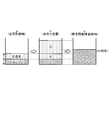
- FIG. 3 is a diagram illustrating an example of calculating the drive power amount.
- the drive power amount calculation unit 13c calculates the drive power amount when the vehicle returns to a place of transmission such as a home and parks, or when a calculation start operation is performed by a driver or the like, the internal power amount disappears. It can be calculated at various occasions such as immediately before, and can be arbitrarily set by the user.
- the other power consumption calculation unit 13d calculates another power consumption indicating the amount of power consumed by another vehicle-mounted device mounted on the vehicle. To give a specific example, the other power consumption calculation unit 13d calculates the other power consumption by acquiring the amount of power consumed from the vehicle-mounted device such as an air conditioner, an audio, and a light mounted on the vehicle.
- the vehicle-mounted device such as an air conditioner, an audio, and a light mounted on the vehicle.
- the diagnosis unit 13e diagnoses the driver's fuel-saving driving based on the drive power amount calculated by the drive power amount calculation unit 13c and the external power amount stored in the external power amount storage unit 13a. Specifically, the diagnosis unit 13e includes the drive power amount “B + D + GC” (or 2G + B + C) calculated by the drive power amount calculation unit 13c and the external power amount acquired by the external power amount storage unit 13a. By substituting “B + D” into equation (1), the driver can diagnose how much electric power charged at home or the like has been consumed for driving. The diagnosis unit 13e stores the diagnosis result (calculation result of the formula (1)) in a memory (not shown) and notifies the fuel-saving driving scoring unit 14 of the result. The result diagnosed here is that the internal electric energy charged at home or the like is divided by the electric energy consumed for driving. When most of the electric energy used for traveling is the internal electric energy, a high numerical value is calculated.
- the fuel-saving driving scoring unit 14 scores the fuel-saving driving of the driver based on the result diagnosed by the diagnosis unit 13e. Specifically, the drive power amount “B + D + GC” (or 2G + B + C) calculated by the drive power amount calculation unit 13c and the external power amount “B + D” acquired by the external power amount storage unit 13a are used. By substituting into equation (2), the driver scores the amount of power consumed at home or the like for driving, and stores the scoring result in a memory (not shown). That is, the fuel-saving driving scoring unit 14 scores the driver's fuel-saving driving by multiplying the result diagnosed by the diagnosis unit 13e by 100. Therefore, the result scored here is a high scoring result when the ratio of the internal electric energy is large in the electric energy consumed for driving, that is, when most of the electric energy used for driving is the internal electric energy. Will be calculated.
- the fuel-saving driving advice generation unit 15 notifies the driver of fuel-saving driving advice based on the result diagnosed by the diagnosis unit 13e.
- the fuel-saving driving advice generation unit 15 acquires the diagnosis result diagnosed by the diagnosis unit 13e from a memory or the like, creates a message corresponding to the result, and notifies the driver. For example, when the diagnosis result is “0.2”, the fuel-saving driving advice generation unit 15 creates a message such as “Let's try eco-driving”, and when the diagnosis result is “0.8”. Create a message such as “Please continue with eco-driving” and notify the driver of fuel-saving driving advice.
- the fuel-saving driving advice generation unit 15 can also notify the driver of fuel-saving driving advice based on the result scored by the fuel-saving driving scoring unit 14. For example, when the scoring result is “20 points”, the fuel-saving driving advice generation unit 15 creates a message such as “Eco driving degree is 20 points. When the diagnosis result is “80 points”, a message such as “eco-driving degree is 80 points. Please continue with eco-driving” will be created to notify the driver of fuel-saving driving advice.
- a format corresponding to the ratio calculated by the diagnosis unit 13e, the result scored by the fuel-saving driving scoring unit 14, or the like is used. It is also possible to select “Messages A and B” by comparing each with a threshold value.
- “eco-driving degree (XX) points. Let's keep eco-driving” should be stored in the memory.
- a comparison with the threshold value for example, if the scoring result is less than the threshold value A, “message A” is stored in the memory, and if it is equal to or higher than the threshold value A, “message B” is stored in the memory. 15 compares the scoring result scored by the fuel-saving driving scoring unit 14 with a threshold value, and selects and notifies the above message.
- the HV traveling control device 20 that performs various controls relating to driving of the vehicle and the devices connected to the HV traveling control device 20 will be described.
- the devices connected to the HV traveling control device 20 include an engine control device 21, a drive motor control device 22, a brake control device 23, a vehicle speed sensor 24, an accelerator operation amount sensor 25, a shift sensor 26, a vehicle speed.
- the HV traveling control device 20 is a device that controls the HV traveling control, obtains various information from each connected device, and outputs the information to the fuel-saving driving diagnosis device 10.
- the power source connection unit 20a and an electric energy DB 20b The HV traveling control device 20 acquires various information and outputs it to the fuel-saving driving diagnosis device 10 when an acquisition request is received from the fuel-saving driving diagnosis device 10 or periodically or in advance. It can be acquired and notified at various triggers (for example, when the vehicle speed becomes 0).
- Examples of information that the HV traveling control device 20 acquires various information and outputs to the fuel-saving driving diagnosis device 10 include, for example, external power amount, internal power amount, vehicle speed, engine speed, select lever signal, accelerator operation amount. (Accelerator opening rate).
- the HV traveling control device 20 includes an engine control device 21, a drive motor control device 22, a brake control device 23, a vehicle speed sensor 24, an accelerator operation amount sensor 25, a shift sensor 26, and a vehicle speed pulse signal integrated value.
- Various information is acquired from the storage unit 27 and the like, and the driving of the vehicle is controlled.
- the HV traveling control device 20 controls the drive motor control device 22 to use electric power as energy.
- the HV traveling control device 20 controls the engine control device 21 so that gasoline is used as energy from a gasoline tank (not shown) when electric power is not stored in the electric energy DB 20b.
- the power source connection unit 20a is a connection unit that charges power from an external device. Specifically, the power source connection unit 20a is connected to an external device such as a home outlet or a charger dedicated to a plug-in hybrid car, receives power supply, and stores the supplied power in a power amount DB 20b described later. In addition, the power source connection unit 20a notifies the external power amount storage unit 13a of the supplied power amount.
- the electric energy DB 20b stores an external electric energy indicating the electric energy charged from the external device and an internal electric energy indicating the electric energy charged when the vehicle is driven. Specifically, the electric energy DB 20b stores the external electric energy charged through the power source connection unit 20a and the internal electric energy charged by driving the engine control device 21 together. The electric energy DB 20b may store the external electric energy and the internal electric energy together, or may store them in separate areas.
- the engine control device 21 controls the gasoline engine that drives the vehicle. Specifically, the engine control device 21 receives an engine rotation rate increase request, an engine rotation rate decrease request, or the like notified from the HV travel control device 20, and controls the engine rotation rate corresponding to each.
- the drive motor control device 22 controls a motor that drives the vehicle using electricity as energy. Specifically, the drive motor control device 22 controls driving of the vehicle by driving the motor using the electric power stored in the electric energy DB 20b based on the motor control notification from the HV driving control device 20.
- the brake control device 23 is connected to a brake pedal or the like of a vehicle (not shown), and controls the mechanical brake according to the driver's brake operation and controls it to be used as a regenerative brake according to the driver's shift lever operation. .
- the vehicle speed sensor 24 detects the current vehicle speed. Specifically, the vehicle speed sensor 24 detects the current vehicle speed displayed by a speedometer or the like and outputs the detected vehicle speed to the HV traveling control device 20.
- the accelerator operation amount sensor 25 detects the current driver's accelerator operation amount. Specifically, the accelerator operation amount sensor 25 is connected to an accelerator pedal or the like of a vehicle (not shown), detects the accelerator operation amount according to the driver's accelerator operation, and outputs it to the HV traveling control device 20.
- the shift sensor 26 detects the position of the shift lever (select lever) of the vehicle. Specifically, the shift sensor 26 is connected to a shift lever or the like of a vehicle (not shown), detects the shift lever in response to the driver's shift lever operation, and outputs a range signal indicating the detected shift lever to the HV traveling control device 20. Output to.
- the vehicle speed pulse signal integrated value storage unit 27 is a value obtained by integrating one by one assuming that a pulse sensor provided on the inner diameter of the wheel of the vehicle detects a vehicle speed pulse signal for each rotation of the wheel. That is, the vehicle speed pulse signal integrated value is a value obtained by integrating the number of wheel rotations. By calculating the vehicle speed pulse signal integrated value for a predetermined time and multiplying by the outer peripheral length of the wheel, the travel distance of the vehicle for the predetermined time can be calculated. Further, the vehicle speed pulse signal integrated value storage unit 27 outputs the calculated travel distance of the vehicle to the HV travel control device 20.
- FIG. 4 is a flowchart illustrating the flow of the fuel-saving driving diagnosis process in the fuel-saving driving diagnosis device according to the first embodiment.
- step S101 when the fuel-saving driving diagnosis device 10 detects that the vehicle engine has been started (Yes in step S101), the fuel-saving driving diagnosis device 10 acquires the external power amount charged at the local point at home or the like from the power amount DB 20b. (Step S102), the internal electric energy charged by an engine using gasoline at the local point is acquired from the electric energy DB 20b and stored (step S103).
- the fuel-saving driving diagnosis device 10 detects that the vehicle has returned to the home, that is, that the vehicle has been parked based on the vehicle speed or the like (Yes at step S104), the remaining power amount at the time of arrival at the home
- the driving power amount used for driving is calculated from the above, the external power amount stored in advance is acquired, and the acquired external power amount is divided by the driving power amount to perform eco-driving diagnosis (step S105).
- the fuel-saving driving diagnosis device 10 notifies the driver of fuel-saving driving advice based on the “external power amount / driving power amount” that is the eco-driving diagnosis result (step S106).
- the fuel-saving driving diagnosis device 10 calculates the amount of power required for the vehicle to drive from the external power amount, the internal power amount, and the power amount that the vehicle holds at the local point.
- the driving power amount shown is calculated, and the fuel-saving driving of the driver is diagnosed based on the calculated driving power amount and the external power amount.
- the fuel-saving driving diagnosis device 10 can calculate how much of the electric power used for driving is consumed by charging from facilities such as home without using gasoline. It is possible to calculate information that can sufficiently encourage the driver of the hybrid car to perform fuel-saving driving.
- the fuel-saving driving diagnosis device 10 also stores the amount of regenerative power generated when the vehicle decelerates, and thus how much of the charged power is consumed without using gasoline. Can be determined accurately.
- the fuel-saving driving diagnosis device 10 scores the driver's fuel-saving driving based on the result of diagnosing the driver's fuel-saving driving, so that the driver can easily understand the information. It can be determined whether or not the fuel-saving driving. As a result, it is possible to further promote fuel-saving driving.
- the fuel-saving driving diagnosis device 10 notifies the driver of fuel-saving driving advice based on the diagnosed result, so that the driver's awareness of fuel-saving driving is improved. As a result, it is possible to further promote fuel-saving driving.
- Advice generation method For example, in the first embodiment, the example of notifying the driver of the advice generated by voice has been described. However, the present invention is not limited to this, and for example, the advice is generated by image data. Then, it can be displayed on the car navigation device 17 or a head-up display (not shown).
- the fuel-saving diagnosis device 10 disclosed in the present application calculates another power consumption amount indicating the amount of power consumed by another vehicle-mounted device mounted on the vehicle, and calculates the calculated drive power amount, The driver's fuel-saving driving can be diagnosed based on the amount of power obtained by subtracting the amount of other power consumption from the amount of external power.
- the fuel-saving diagnostic device 10 acquires the amount of power consumed from the vehicle-mounted device such as an air conditioner, an audio, and a light mounted on the vehicle, and calculates the other power consumption by the other power consumption calculation unit 13d. And as shown in Formula (3), the fuel-saving diagnostic device 10 diagnoses the driver's fuel-saving driving by subtracting the other power consumption amount from the external power amount charged at home or the like. In this way, the fuel-saving diagnostic device 10 can accurately calculate the internal electric energy required only for traveling, and how much the driver uses the internal electric energy only for traveling, that is, the driver It is possible to determine the power ratio with respect to running. As a result, the fuel saving diagnostic device 10 can also more accurately diagnose the driver's fuel saving driving.
- the vehicle-mounted device such as an air conditioner, an audio, and a light mounted on the vehicle
- the fuel-saving diagnostic device 10 diagnoses the driver's fuel-saving driving by subtracting the other power consumption amount from the external power amount charged at home or the like. In this way, the fuel-saving diagnostic device 10 can accurately
- the fuel-saving diagnostic device 10 can also diagnose the driver's fuel-saving driving based on the power amount obtained by adding the other power consumption amount to the calculated drive power amount and the external power amount. Specifically, as shown in Expression (4), the fuel-saving diagnostic device 10 diagnoses the driver's fuel-saving driving by using the power amount obtained by adding the other power consumption amount to the calculated driving power amount. . In this way, the fuel-saving diagnostic device 10 can accurately calculate the amount of power used in the traveling vehicle, and how much internal power is used by the driver during traveling, that is, driving It is possible to determine the power ratio with respect to the user's use. As a result, the fuel saving diagnostic device 10 can also more accurately diagnose the driver's fuel saving driving.
- the first embodiment includes an external power amount storage unit 13a, an internal power amount storage unit 13b, a drive power amount calculation unit 13c, another power consumption calculation unit 13d, and a diagnosis unit 13e.
- the fuel-saving driving diagnosis unit 13 and the HV traveling control device 20 can perform each function. It can also be distributed.
- the diagnosis unit 13e is replaced with the fuel-saving driving diagnosis unit 13, the external power amount storage unit 13a, the internal power amount storage unit 13b, the drive power amount calculation unit 13c, and the other power consumption calculation unit. 13d may be distributed in the HV traveling control device 20.
- FIG. 5 is a diagram illustrating an example of an in-vehicle system in which fuel-saving driving diagnosis functions are distributed.
- the vehicle system 1 is not necessarily provided with the fuel-saving driving diagnosis unit 13 and the HV control device 20 separately.
- the HV control device 20 is diagnosed with a fuel-saving driving diagnosis. It is good also as a structure incorporated in the part 13. FIG.
- each component of each illustrated apparatus is functionally conceptual and does not necessarily need to be physically configured as illustrated.
- the specific form of distribution / integration of each device is not limited to that shown in the figure, and all or a part thereof may be functionally or physically distributed or arbitrarily distributed in arbitrary units according to various loads or usage conditions.
- the external power storage unit 13a and the internal power storage unit 13b may be integrated.
- all or any part of each processing function performed in each device may be realized by a CPU and a program analyzed and executed by the CPU, or may be realized as hardware by wired logic.
- the fuel-saving driving diagnosis method described in the present embodiment can be realized by executing a program prepared in advance on a computer such as a personal computer or a workstation.
- This program can be distributed via a network such as the Internet.
- the program can also be executed by being recorded on a computer-readable recording medium such as a hard disk, a flexible disk (FD), a CD-ROM, an MO, and a DVD and being read from the recording medium by the computer.
- the fuel-saving driving diagnosis device, the in-vehicle system, the drive control device, and the fuel-saving driving diagnosis program according to the present invention are useful for diagnosing the driver's fuel-saving driving in a vehicle that uses electricity as energy.
- it is suitable for calculating information that can sufficiently promote fuel-saving driving for the driver of the plug-in hybrid car.
Landscapes
- Engineering & Computer Science (AREA)
- Transportation (AREA)
- Mechanical Engineering (AREA)
- Chemical & Material Sciences (AREA)
- Combustion & Propulsion (AREA)
- Power Engineering (AREA)
- Automation & Control Theory (AREA)
- Human Computer Interaction (AREA)
- Electric Propulsion And Braking For Vehicles (AREA)
- Hybrid Electric Vehicles (AREA)
- Control Of Vehicle Engines Or Engines For Specific Uses (AREA)
- Combined Controls Of Internal Combustion Engines (AREA)
Abstract
省燃費運転診断装置は、外部装置から充電された電力量を示す外部電力量と、車両が駆動することにより充電された電力量を示す内部電力量とを記憶する。そして、省燃費運転診断装置は、記憶される外部電力量と内部電力量と車両が現地点で保持している電力量とから、車両が駆動に要した電力量を示す駆動電力量を算出し、算出された駆動電力量と、記憶される外部電力量とに基づいて、省燃費運転を診断する。その結果、プラグインハイブリッドカーの運転者に対して、省燃費運転を十分に促すことができる情報を算出する。
Description
本発明は、電気をエネルギーとして駆動する車両における運転者の省燃費運転を診断する省燃費運転診断装置、車載システム、駆動制御装置および省燃費運転診断プログラムに関する。
近年、地球温暖化対策などの地球環境問題がクローズアップされ、石油などの化石燃料を用いることによる二酸化炭素の排出、特に、ガソリンを用いる自動車などの排出ガスなどが問題となっている。
このような問題の対策として、太陽電池を電源とするソーラーカー、燃料電池を用いる燃料電池カー、ガソリンと電力(電気モータ)とを用いるハイブリッドカーなど、排出ガスを低減する様々な電気自動車が開発されている。
上記した電気自動車は、ガソリンを用いたエンジンを駆動させて自動車を走行させる一方で、当該エンジンを駆動することによりエネルギーとなる電気を充電している。最近では、エンジンを用いて電力を充電する必要がなく、自宅などのコンセントから電気を充電することのできるプラグインハイブリッドカーなどの電気自動車が開発されている。このような様々な自動車から排出される排出ガスは、依然として大きな問題であることから、自動車を運転する運転者に対して、排出ガス低減を促す様々な技術が開示されている。
例えば、ハイブリッドカーの走行距離と燃料消費量とに基づいて算出された瞬間燃費とハイブリッドカーの加速度とを用いて、ハイブリッドカーの走行効率を算出して、運転者に表示する技術が開示されている(例えば、特許文献1参照)。
しかしながら、上記した従来の技術をプラグインハイブリッドカーに適用した場合、プラグインハイブリッドカーの特性を考慮できないので、走行効率を正確に判定することができず、運転者に対して省燃費運転を促すには不十分な情報しか算出できないという課題があった。
本発明は、上記に鑑みてなされたものであって、プラグインハイブリッドカーの運転者に対して、省燃費運転を十分に促すことができる情報を算出することが可能である省燃費運転診断装置、車載システム、駆動制御装置および省燃費運転診断プログラムを提供することを目的とする。
上述した課題を解決し、目的を達成するため、本発明は、外部装置から充電された電力量を示す外部電力量を記憶する外部電力量記憶部と、車両の駆動により発電された電力で充電された電力量を示す内部電力量を記憶する内部電力量記憶部と、前記外部電力量記憶部に記憶される外部電力量と、前記内部電力量記憶部に記憶される内部電力量と、前記車両が現地点で保持している電力量とから、車両が駆動に要した電力量を示す駆動電力量を算出する駆動電力量算出部と、前記駆動電力量算出部により算出された駆動電力量と、前記外部電力量記憶部に記憶される外部電力量とに基づいて、省燃費運転を診断する省燃費運転診断部と、を備えたことを特徴とする。
本発明によれば、プラグインハイブリッドカーの運転者に対して、省燃費運転を十分に促すことができる情報を算出することが可能であるという効果を奏する。
また、本発明によれば、車両が駆動することにより発電される回生電力量もあわせて記憶するので、ガソリンを用いることなく充電された電力量がどのくらい消費されているかを正確に判断することが可能である。
また、本発明によれば、走行のみに要した内部電力量を正確に算出することができ、運転者が走行のみにどのくらい内部電力量を使用したか、つまり、運転者の走行に対する電力比を判断することができる。
また、本発明によれば、走行する車両において使用した電力量を正確に算出することができ、運転者が走行中にどのくらいの内部電力量を使用したか、つまり、運転者の使用に対する電力比を判断することができる。
また、本発明によれば、運転者の省燃費運転を診断した結果に基づいて、運転者の省燃費運転を採点するので、運転者に対して、わかり易い情報で省燃費運転か否かを判定することができる。
また、本発明によれば、診断された結果に基づいて、運転者に対して省燃費運転のアドバイスを通知するので、運転者の省燃費運転意識を向上させることができ、その結果、省燃費運転をより促すことが可能である。
以下に、この発明に係る省燃費運転診断装置、車載システム、駆動制御装置および省燃費運転診断プログラムの実施例を詳細に説明する。また、以下では、本実施例に係る省燃費運転診断装置の概要、省燃費運転診断装置の構成および処理の流れを順に説明し、最後に本実施例に対する種々の変形例を説明する。なお、この実施例によりこの発明が限定されるものではない。
[省燃費運転診断装置の概要]
まず、図1を用いて、実施例1に係る省燃費運転診断装置の概要について説明する。図1は、実施例1に係る省燃費運転診断装置の概要を説明するための図である。図1に示すように、実施例1に係る省燃費運転診断装置10は、プラグインハイブリッドカーなどの電気自動車における車載システムに搭載される装置であり、車両における運転者の省燃費運転を診断する。
まず、図1を用いて、実施例1に係る省燃費運転診断装置の概要について説明する。図1は、実施例1に係る省燃費運転診断装置の概要を説明するための図である。図1に示すように、実施例1に係る省燃費運転診断装置10は、プラグインハイブリッドカーなどの電気自動車における車載システムに搭載される装置であり、車両における運転者の省燃費運転を診断する。
また、この車載システム1には、当該省燃費運転診断装置10と、車内に音声を出力するスピーカー16と、運転席者などに対して運転支援を行うカーナビゲーション装置17とが接続されるとともに、省燃費運転診断装置10とバス100を介して接続される車両の駆動に関する各種制御を行うHV走行制御装置20とを有する。もっとも、ここで図示した省燃費運転診断装置10は、あくまで本発明を説明するための例示であり、これに限定されるものではなく、例えば、エアコン、空気清浄機など自動車に搭載されている各種装置が含まれていてもよい。
このような省燃費運転診断装置10は、自宅などの外部装置から充電された電力量を示す外部電力量と、車両が駆動することにより充電された電力量を示す内部電力量とを記憶する。そして、省燃費運転診断装置10は、記憶される外部電力量と記憶される内部電力量と車両が現地点で保持している電力量とから、車両が駆動に要した電力量を示す駆動電力量を算出し、算出された駆動電力量と、外部電力量とに基づいて、運転者の省燃費運転を診断する。その結果、省燃費運転診断装置10は、プラグインハイブリッドカーの運転者に対して、省燃費運転を十分に促すことができる情報を算出することが可能である。
具体的には、車両が自宅から走行して自宅に戻ってきた時の残電力量が、図1の(a)に示すように、自宅で充電された外部電力量(B)とエンジンにより充電された内部電力量(C)であったとする。そして、運転者は、自宅で電力量の充電を行い、図1の(b)に示すように、外部電力量が(D)だけ増加する。つまり、省燃費運転診断装置10は、この状態において、車両に格納されている外部電力量を(B+D)、内部電力量を(C)として記憶していることになる。
そして、省燃費運転診断装置10は、図1の(c)に示すように、上記した電力量を保持する車両が自宅を出て、再び自宅に戻ってきた場合に、記憶される内部電力量「C」と記憶される外部電力量「B+D」と自宅に到着した車両に残っている電力量「E」とから、車両が駆動に消費した電力量を示す駆動電力量「D+B+E-C」を算出する。続いて、省燃費運転診断装置10は、『外部電力量「D+B」/駆動電力量「D+B+E-C」』を算出し、算出した「(D+B)/(D+B+E-C)」を運転者の省燃費運転診断結果とする。
このように、実施例1に係る省燃費運転診断装置10は、走行に使用した電力のうち、ガソリンを使わずに自宅などの設備から充電して使用した電力をどのくらい消費したかを算出することができる結果、プラグインハイブリッドカーの運転者に対して、省燃費運転を十分に促すことができる情報を算出することが可能である。
[省燃費運転診断装置の構成]
次に、図2を用いて、実施例1に係る省燃費運転診断装置の構成を説明する。図2は、実施例1に係る省燃費運転診断装置を含む車載システムの構成を示すブロック図である。
次に、図2を用いて、実施例1に係る省燃費運転診断装置の構成を説明する。図2は、実施例1に係る省燃費運転診断装置を含む車載システムの構成を示すブロック図である。
図2に示すように、この車載システム1は、省燃費運転診断装置10と、スピーカー16と、カーナビゲーション装置17と、HV(ハイブリッド)走行制御装置20と、エンジン制御装置21と、駆動モータ制御装置22と、ブレーキ制御装置23と、車速センサ24と、アクセル操作量センサ25と、シフトセンサ26と、車速パルス信号積算値格納部27とを有する。
このうち、スピーカー16は、省燃費運転診断装置10から入力された各種音声信号を音声として車内に出力したり、図示しないラジオや音楽プレーヤーなどから入力された各種音声信号を音声として車内に出力したりする。また、カーナビゲーション装置17は、タッチパネルや液晶などを有し、地図情報や道路情報などを表示したり、記憶する地図情報や道路情報から車両が現在走行している道路に関する情報を省燃費運転診断装置10に出力したりする一般的なカーナビゲーションである。
(省燃費運転診断装置10の構成)
省燃費運転診断装置10は、出力インタフェース部11と、車載ネットワークインタフェース部12と、省燃費運転診断部13と、省燃費運転採点部14と、省燃費運転アドバイス生成部15とを有する。
省燃費運転診断装置10は、出力インタフェース部11と、車載ネットワークインタフェース部12と、省燃費運転診断部13と、省燃費運転採点部14と、省燃費運転アドバイス生成部15とを有する。
出力インタフェース部11は、省燃費運転診断装置10とスピーカー16との間でやり取りする各種情報に関する通信を制御するインタフェースであり、例えば、後述する省燃費運転診断部13から出力された運転者の省燃費運転診断結果、省燃費運転採点部14から出力された運転者の省燃費運転採点結果、省燃費運転アドバイス生成部15から出力された運転者への省燃費運転アドバイスなどを受け付けて、スピーカー16に出力する。
車載ネットワークインタフェース部12は、省燃費運転診断装置10と後述するHV走行制御装置20との間でやり取りする各種情報に関する通信を制御するインタフェースであり、例えば、省燃費運転診断装置10から出力される各種要求(例えば、各種電力量取得要求やエンジン回転数速度取得要求など)を受け付けて、HV走行制御装置20に対して出力したり、HV走行制御装置20から出力される各種応答(例えば、電力量情報やエンジン回転数情報など)を受け付けて、省燃費運転診断装置10に対して出力したりする。
省燃費運転診断部13は、電気をエネルギーとして駆動する車両における運転者の省燃費運転を診断する制御部であり、特に本発明に密接に関連するものとしては、外部電力量記憶部13aと、内部電力量記憶部13bと、駆動電力量算出部13cと、他消費電力算出部13dと、診断部13eとを有する。
外部電力量記憶部13aは、外部装置から充電された電力量を示す外部電力量を記憶する。具体的には、外部電力量記憶部13aは、後述するHV走行制御装置20の電力量DB20bに記憶される電力量から、自宅などの外部装置から充電された電力量を示す外部電力量を取得して記憶する。また、外部電力量記憶部13aは、後述するHV走行制御装置20の電力源接続部20aから電力量DB20bに格納された外部電力量も記憶する。さらに、外部電力量記憶部13aは、減速時にモータを発電機として用いて発電される回生電力量もあわせて記憶するようにしてもよい。例えば、外部電力量記憶部13aは、電力量DB20bに記憶される電力量「A」のうち自宅で充電された電力量「B」、電力源接続部20aから電力量DB20bに格納された外部電力量が「D」である場合、外部電力量として「B+D」を記憶する。
なお、外部電力とは、効率よく発電された電力であり、環境への負荷が少なく、外部電力を使用した場合、省燃費運転の評価はプラスの評価がなされる。
内部電力量記憶部13bは、車両が駆動することにより発電された電力量を示す内部電力量を記憶する。具体的には、内部電力量記憶部13bは、後述するHV走行制御装置20の電力量DB20bに記憶される電力量から、ガソリンを用いてエンジンが駆動して、車両が走行することにより充電された電力量を示す内部電力量を取得して記憶する。例えば、内部電力量記憶部13bは、電力量DB20bに記憶される電力量「A」のうち車両が走行することにより充電された電力量「C」である場合、内部電力量として「C」を記憶する。
なお、内部電力とは、エンジンの駆動により発電された電力であるため、エンジンを使用した時点で環境運転の観点から好ましいものではなく、内部電力を使用した場合、省燃費運転の評価はマイナスの評価がなされる。
駆動電力量算出部13cは、外部電力量記憶部13aに記憶される外部電力量と内部電力量記憶部13bに記憶される内部電力量と車両が現地点で保持している電力量とから、車両が駆動に要した電力量を示す駆動電力量を算出する。具体的に例を挙げれば、駆動電力量算出部13cは、外部電力量記憶部13aが取得した外部電力量が「B+D」、内部電力量記憶部13bから取得した内部電力量が「C」、車両が現地点で保持している電力量が「G」である場合、車両が駆動に要した電力量を示す駆動電力量を「B+D+G-C」として算出する。
また、車両が現地点で保持している電力量が「G」である場合、つまり、外部電力量を全て使ってしまい、電力量を充電しつつ走行していた場合であっても、駆動電力量を正確に算出することができる。具体的には、駆動電力量算出部13cは、図3の(a)に示すように、自宅到着時の内部電力量が「B」、外部電力量が「C」であり、図3の(b)に示すように、自宅でさらに電力量「D」が充電されて走行した後、図3の(c)に示すように、外部電力量「G」のみが残っていたとする。この場合、駆動電力量算出部13cは、外部電力量が「B+D」、内部電力量が「C+G」、車両が現地点で保持している電力量が「G」となり、車両が駆動に要した電力量を示す駆動電力量を「D+B+C+G-(D-G)=2G+B+C」として算出することができる。なお、図3は、駆動電力量を算出する例を示す図である。
また、駆動電力量算出部13cが駆動電力量を算出するタイミングとしては、車両が自宅など発信場所に戻ってきて駐車した場合、運転者などの算出開始操作がされた場合、内部電力量がなくなる直前など様々な契機で算出することができ、ユーザにより任意に設定することができる。
他消費電力算出部13dは、車両に搭載される他の車載器により消費された電力量を示す他消費電力量を算出する。具体的に例を挙げれば、他消費電力算出部13dは、車両に搭載されるエアコン、オーディオ、ライトなどの車載器から消費した電力量を取得して他消費電力量を算出する。
診断部13eは、駆動電力量算出部13cにより算出された駆動電力量と、外部電力量記憶部13aに記憶される外部電力量とに基づいて、運転者の省燃費運転を診断する。具体的に例を挙げると、診断部13eは、駆動電力量算出部13cにより算出された駆動電力量「B+D+G-C」(または、2G+B+C)と、外部電力量記憶部13aが取得した外部電力量「B+D」とを式(1)に代入することにより、運転者が自宅などで充電された電力がどのくらい駆動に消費されたのかを診断することができる。また、診断部13eは、診断した結果(式(1)の算出結果)を図示しないメモリなどに格納するとともに、当該結果を省燃費運転採点部14に通知する。ここで診断される結果は、自宅などで充電した内部電力量を駆動に消費した電力量で除算していることより、駆動に消費した電力量のうち内部電力量の割合が多い場合、すなわち、走行に用いた電力量の多くが内部電力量である場合には、高い数値が算出されることとなる。

省燃費運転採点部14は、診断部13eにより診断された結果に基づいて、運転者の省燃費運転を採点する。具体的に例を挙げれば、駆動電力量算出部13cにより算出された駆動電力量「B+D+G-C」(または、2G+B+C)と、外部電力量記憶部13aが取得した外部電力量「B+D」とを式(2)に代入することにより、運転者が自宅などで充電された電力がどのくらい駆動に消費されたのかを採点して、図示しないメモリなどに採点結果を格納する。つまり、省燃費運転採点部14は、診断部13eにより診断された結果に100を乗算することにより、運転者の省燃費運転を採点する。したがって、ここで採点される結果は、駆動に消費した電力量のうち内部電力量の割合が多い場合、すなわち、走行に用いた電力量の多くが内部電力量である場合には、高い採点結果が算出されることとなる。

省燃費運転アドバイス生成部15は、診断部13eにより診断された結果に基づいて、運転者に対して省燃費運転のアドバイスを通知する。具体的に例を挙げれば、省燃費運転アドバイス生成部15は、診断部13eにより診断された診断結果をメモリなどから取得し、その結果に応じたメッセージを作成して運転者に通知する。例えば、省燃費運転アドバイス生成部15は、診断結果が「0.2」である場合に「エコ運転を心がけましょう」などのメッセージを作成し、診断結果が「0.8」である場合に「これからもエコ運転でお願いします」などのメッセージを作成して、運転者に対して省燃費運転のアドバイスを通知する。
また、省燃費運転アドバイス生成部15は、省燃費運転採点部14により採点された結果に基づいて、運転者に対して省燃費運転のアドバイスを通知することもできる。具体的に例を挙げれば、省燃費運転アドバイス生成部15は、採点結果が「20点」である場合に「エコ運転度20点です。エコ運転を心がけましょう」などのメッセージを作成し、診断結果が「80点」である場合に「エコ運転度80点です。これからもエコ運転でお願いします」などのメッセージを作成して、運転者に対して省燃費運転のアドバイスを通知する。
なお、ここで省燃費運転アドバイス生成部15がメッセージを作成する手法としては、診断部13eにより算出された割合や省燃費運転採点部14により採点された結果などに対応付けたフォーマットなどを用いることで実現でき、それぞれと閾値とを比較して「メッセージA、B」を選択するようにしてもよい。フォーマットの例としては、「エコ運転度(XX)点。エコ運転を心がけましょう」などをメモリに記憶させておけばよい。また、閾値との比較としては、例えば、採点結果が閾値A未満であれば「メッセージA」、閾値A以上であれば「メッセージB」などをメモリに格納しておき、省燃費運転アドバイス生成部15は、省燃費運転採点部14により採点された採点結果と閾値とを比較して、上記したメッセージを選択して通知する。
こうすることにより、さらに細かなメッセージ選択を実施することができ、運転者に省燃費運転をより強く促すことができる。また、上記した例では、閾値Aと閾値Bとの2つの閾値を用いてメッセージを選択する例について説明したが、これに限定されるものではなく、閾値を3つ以上用いて、メッセージを選択するようにしてもよい。
(HV走行制御装置20と各種装置の構成)
次に、車両の駆動に関する各種制御を行うHV走行制御装置20とHV走行制御装置20に接続される各装置について説明する。HV走行制御装置20に接続される装置としては、エンジン制御装置21と、駆動モータ制御装置22と、ブレーキ制御装置23と、車速センサ24と、アクセル操作量センサ25と、シフトセンサ26と、車速パルス信号積算値格納部27とがある。
次に、車両の駆動に関する各種制御を行うHV走行制御装置20とHV走行制御装置20に接続される各装置について説明する。HV走行制御装置20に接続される装置としては、エンジン制御装置21と、駆動モータ制御装置22と、ブレーキ制御装置23と、車速センサ24と、アクセル操作量センサ25と、シフトセンサ26と、車速パルス信号積算値格納部27とがある。
HV走行制御装置20は、HVの走行制御をつかさどる制御を行うとともに、接続される各装置から各種情報を取得して、省燃費運転診断装置10に出力する装置であり、特に、電力源接続部20aと電力量DB20bとを有する。当該HV走行制御装置20が各種情報を取得して省燃費運転診断装置10に出力する契機としては、省燃費運転診断装置10から取得要求を受け付けた場合や定期的、さらには、予め定めた契機(例えば、車速が0となった場合)など様々な契機で、取得・通知することができる。また、HV走行制御装置20が各種情報を取得して省燃費運転診断装置10に出力する情報としては、例えば、外部電力量、内部電力量、車速、エンジン回転率、セレクトレバー信号、アクセル操作量(アクセル開度率)などがある。
また、HV走行制御装置20は、エンジン制御装置21と、駆動モータ制御装置22と、ブレーキ制御装置23と、車速センサ24と、アクセル操作量センサ25と、シフトセンサ26と、車速パルス信号積算値格納部27などから各種情報を取得して、車両の駆動を制御する。例えば、HV走行制御装置20は、電力量DB20bに電力が記憶されている場合には、電力をエネルギーとして用いるように、駆動モータ制御装置22を制御する。また、HV走行制御装置20は、電力量DB20bに電力が記憶されていない場合には、図示しないガソリンタンクからガソリンをエネルギーとして用いるように、エンジン制御装置21を制御する。
電力源接続部20aは、外部装置から電力を充電する接続部である。具体的には、電力源接続部20aは、自宅内のコンセントやプラグインハイブリッドカー専用充電器など外部装置と接続して電力供給を受け、供給された電力を後述する電力量DB20bに格納する。また、電力源接続部20aは、供給された電力量を外部電力量記憶部13aに通知する。
電力量DB20bは、外部装置から充電された電力量を示す外部電力量と車両が駆動することにより充電された電力量を示す内部電力量とをあわせて記憶する。具体的には、電力量DB20bは、電力源接続部20aを介して充電された外部電力量とエンジン制御装置21が駆動することにより充電された内部電力量とをあわせて記憶する。なお、電力量DB20bは、外部電力量と内部電力量とをあわせて記憶してもよく、別々の領域に記憶してもよい。
エンジン制御装置21は、車両を駆動するガソリンエンジンを制御する。具体的には、エンジン制御装置21は、HV走行制御装置20から通知されるエンジン回転率上昇要求やエンジン回転率下降要求などを受け付けて、それぞれに対応したエンジン回転率を制御する。
駆動モータ制御装置22は、電気をエネルギーとして車両を駆動するモータを制御する。具体的には、駆動モータ制御装置22は、HV走行制御装置20からモータ制御通知に基づいて、電力量DB20bに記憶される電力を用いてモータを駆動させて、車両の走行を制御する。
ブレーキ制御装置23は、図示しない車両のブレーキペダルなどに接続され、運転者のブレーキ操作に応じてメカニカルブレーキを制御するとともに、運転者のシフトレバー操作に応じて回生ブレーキとして使用する様に制御する。車速センサ24は、現在の車両の車速を検知する。具体的には、車速センサ24は、スピードメータなどの表示される現在の車両の車速を検知してHV走行制御装置20に出力する。
アクセル操作量センサ25は、現在の運転者のアクセル操作量を検知する。具体的には、アクセル操作量センサ25は、図示しない車両のアクセルペダルなどに接続され、運転者のアクセル操作に応じてアクセル操作量を検知してHV走行制御装置20に出力する。
シフトセンサ26は、車両のシフトレバー(セレクトレバー)の位置を検知する。具体的には、シフトセンサ26は、図示しない車両のシフトレバーなどに接続され、運転者のシフトレバー操作に応じてシフトレバーを検知し、検知したシフトレバーを示すレンジ信号をHV走行制御装置20に出力する。
車速パルス信号積算値格納部27は、車両の車輪の内径に備えられたパルスセンサが車輪の1回転毎に車速パルス信号を検知したとして1ずつ積算した値である。すなわち、車速パルス信号積算値は、車輪の回転回数を積算した値である。所定時間の車速パルス信号積算値を算出して車輪の外周長を乗じることによって、該所定時間の車両の走行距離を算出することができる。また、車速パルス信号積算値格納部27は、算出した車両の走行距離をHV走行制御装置20に出力する。
[省燃費運転診断装置による処理]
次に、図4を用いて、実施例1に係る省燃費運転診断装置による処理を説明する。図4は、実施例1に係る省燃費運転診断装置における省燃費運転診断処理の流れを示すフローチャートである。
次に、図4を用いて、実施例1に係る省燃費運転診断装置による処理を説明する。図4は、実施例1に係る省燃費運転診断装置における省燃費運転診断処理の流れを示すフローチャートである。
図4に示すように、省燃費運転診断装置10は、車両のエンジンが起動したことを検知すると(ステップS101肯定)、現地点で自宅などで充電された外部電力量を電力量DB20bから取得して記憶するとともに(ステップS102)、現地点でガソリンを用いたエンジンなどで充電された内部電力量を電力量DB20bから取得して記憶する(ステップS103)。
その後、省燃費運転診断装置10は、当該車両が自宅に戻ったこと、すなわち、車両が駐車したことを車速などに基づいて検知すると(ステップS104肯定)、自宅に到着した時点での残電力量から駆動に使用した駆動電力量を算出するとともに、予め記憶する外部電力量を取得し、取得した外部電力量を駆動電力量で除算して、エコ運転診断を行う(ステップS105)。
そして、省燃費運転診断装置10は、エコ運転診断結果である「外部電力量/駆動電力量」に基づいて、運転者に対して省燃費運転のアドバイスを通知する(ステップS106)。
[実施例1による効果]
このように、実施例1によれば、省燃費運転診断装置10は、外部電力量と内部電力量と車両が現地点で保持している電力量とから、車両が駆動に要した電力量を示す駆動電力量を算出し、算出された駆動電力量と外部電力量とに基づいて、運転者の省燃費運転を診断する。その結果、省燃費運転診断装置10は、走行に使用した電力のうち、ガソリンを使わずに自宅などの設備から充電して使用した電力をどのくらい消費したかを算出することができる結果、プラグインハイブリッドカーの運転者に対して、省燃費運転を十分に促すことができる情報を算出することが可能である。
このように、実施例1によれば、省燃費運転診断装置10は、外部電力量と内部電力量と車両が現地点で保持している電力量とから、車両が駆動に要した電力量を示す駆動電力量を算出し、算出された駆動電力量と外部電力量とに基づいて、運転者の省燃費運転を診断する。その結果、省燃費運転診断装置10は、走行に使用した電力のうち、ガソリンを使わずに自宅などの設備から充電して使用した電力をどのくらい消費したかを算出することができる結果、プラグインハイブリッドカーの運転者に対して、省燃費運転を十分に促すことができる情報を算出することが可能である。
また、実施例1によれば、省燃費運転診断装置10は、車両の減速時に発電される回生電力量もあわせて記憶するので、ガソリンを用いることなく充電された電力量がどのくらい消費されているかを正確に判断することが可能である。
また、実施例1によれば、省燃費運転診断装置10は、運転者の省燃費運転を診断した結果に基づいて、運転者の省燃費運転を採点するので、運転者に対して、わかり易い情報で省燃費運転か否かを判定することができる。その結果、省燃費運転をより促すことが可能である。
また、実施例1によれば、省燃費運転診断装置10は、診断された結果に基づいて、運転者に対して省燃費運転のアドバイスを通知するので、運転者の省燃費運転意識を向上させることができ、その結果、省燃費運転をより促すことが可能である。
さて、これまで本発明の実施例について説明したが、本発明は上述した実施例以外にも、種々の異なる形態にて実施されてよいものである。そこで、以下に示すように、(1)アドバイス生成手法、(2)診断手法、(3)機能構成、(4)システム構成等、(5)プログラムにそれぞれ区分けして異なる実施例を説明する。
(1)アドバイス生成手法
例えば、実施例1では、音声により生成したアドバイスを運転者に通知する例について説明したが、本発明はこれに限定されるものではなく、例えば、アドバイスを画像データで生成して、カーナビゲーション装置17や図示しないヘッドアップディスプレイなどに表示出力することもできる。
例えば、実施例1では、音声により生成したアドバイスを運転者に通知する例について説明したが、本発明はこれに限定されるものではなく、例えば、アドバイスを画像データで生成して、カーナビゲーション装置17や図示しないヘッドアップディスプレイなどに表示出力することもできる。
(2)診断手法
例えば、本願が開示する省燃費診断装置10は、車両に搭載される他の車載器により消費された電力量を示す他消費電力量を算出し、算出した駆動電力量と、外部電力量から他消費電力量を差し引いた電力量とに基づいて、運転者の省燃費運転を診断することもできる。
例えば、本願が開示する省燃費診断装置10は、車両に搭載される他の車載器により消費された電力量を示す他消費電力量を算出し、算出した駆動電力量と、外部電力量から他消費電力量を差し引いた電力量とに基づいて、運転者の省燃費運転を診断することもできる。
具体的には、省燃費診断装置10は、車両に搭載されるエアコン、オーディオ、ライトなどの車載器から消費した電力量を取得して他消費電力量を他消費電力算出部13dで算出する。そして、省燃費診断装置10は、式(3)に示すように、自宅等で充電した外部電力量から他消費電力量を差し引いて運転者の省燃費運転を診断する。このようにすることで、省燃費診断装置10は、走行のみに要した内部電力量を正確に算出することができ、運転者が走行のみにどのくらい内部電力量を使用したか、つまり、運転者の走行に対する電力比を判断することができる。その結果、省燃費診断装置10は、運転者の省燃費運転をより正確に診断することもできる。

また、省燃費診断装置10は、算出された駆動電力量に他消費電力量を加えた電力量と、外部電力量とに基づいて、運転者の省燃費運転を診断することもできる。具体的には、省燃費診断装置10は、式(4)に示すように、算出された駆動電力量に他消費電力量を加えた電力量を用いて、運転者の省燃費運転を診断する。このようにすることで、省燃費診断装置10は、走行する車両において使用した電力量を正確に算出することができ、運転者が走行中にどのくらいの内部電力量を使用したか、つまり、運転者の使用に対する電力比を判断することができる。その結果、省燃費診断装置10は、運転者の省燃費運転をより正確に診断することもできる。

(3)機能構成
例えば、実施例1では、外部電力量記憶部13aと、内部電力量記憶部13bと、駆動電力量算出部13cと、他消費電力算出部13d、診断部13eとを有している場合について説明したが、本発明はこれに限定されるものではなく、これら全ての機能を有している必要はなく、省燃費運転診断部13とHV走行制御装置20とで各機能を分散することもできる。例えば、図5に示すように、診断部13eを省燃費運転診断部13に、外部電力量記憶部13aと、内部電力量記憶部13bと、駆動電力量算出部13cと、他消費電力算出部13dとをHV走行制御装置20に分散して設けることもできる。なお、図5は、省燃費運転診断機能を分散させた車載システムの例を示す図である。
例えば、実施例1では、外部電力量記憶部13aと、内部電力量記憶部13bと、駆動電力量算出部13cと、他消費電力算出部13d、診断部13eとを有している場合について説明したが、本発明はこれに限定されるものではなく、これら全ての機能を有している必要はなく、省燃費運転診断部13とHV走行制御装置20とで各機能を分散することもできる。例えば、図5に示すように、診断部13eを省燃費運転診断部13に、外部電力量記憶部13aと、内部電力量記憶部13bと、駆動電力量算出部13cと、他消費電力算出部13dとをHV走行制御装置20に分散して設けることもできる。なお、図5は、省燃費運転診断機能を分散させた車載システムの例を示す図である。
また、車両システム1は、図1に示したように、必ずしも省燃費運転診断部13とHV制御装置20とを分離して設けている必要はなく、例えば、HV制御装置20を省燃費運転診断部13に組み込んだ構成としてもよい。
(4)システム構成等
また、本実施例において説明した各処理のうち、自動的におこなわれるものとして説明した処理の全部または一部を手動的におこなうこともできる。この他、上記文書中や図面中で示した処理手順、制御手順、具体的名称、各種のデータやパラメータを含む情報については、特記する場合を除いて任意に変更することができる。
また、本実施例において説明した各処理のうち、自動的におこなわれるものとして説明した処理の全部または一部を手動的におこなうこともできる。この他、上記文書中や図面中で示した処理手順、制御手順、具体的名称、各種のデータやパラメータを含む情報については、特記する場合を除いて任意に変更することができる。
また、図示した各装置の各構成要素は機能概念的なものであり、必ずしも物理的に図示の如く構成されていることを要しない。すなわち、各装置の分散・統合の具体的形態は図示のものに限られず、その全部または一部を、各種の負荷や使用状況などに応じて、任意の単位で機能的または物理的に分散・統合(例えば、外部電力量記憶部13aと内部電力量記憶部13bとを統合するなど)して構成することができる。さらに、各装置にて行なわれる各処理機能は、その全部または任意の一部が、CPUおよび当該CPUにて解析実行されるプログラムにて実現され、あるいは、ワイヤードロジックによるハードウェアとして実現され得る。
(5)プログラム
なお、本実施例で説明した省燃費運転診断方法は、あらかじめ用意されたプログラムをパーソナルコンピュータやワークステーションなどのコンピュータで実行することによって実現することができる。このプログラムは、インターネットなどのネットワークを介して配布することができる。また、このプログラムは、ハードディスク、フレキシブルディスク(FD)、CD-ROM、MO、DVDなどのコンピュータで読み取り可能な記録媒体に記録され、コンピュータによって記録媒体から読み出されることによって実行することもできる。
なお、本実施例で説明した省燃費運転診断方法は、あらかじめ用意されたプログラムをパーソナルコンピュータやワークステーションなどのコンピュータで実行することによって実現することができる。このプログラムは、インターネットなどのネットワークを介して配布することができる。また、このプログラムは、ハードディスク、フレキシブルディスク(FD)、CD-ROM、MO、DVDなどのコンピュータで読み取り可能な記録媒体に記録され、コンピュータによって記録媒体から読み出されることによって実行することもできる。
以上のように、本発明に係る省燃費運転診断装置、車載システム、駆動制御装置および省燃費運転診断プログラムは、電気をエネルギーとして駆動する車両における運転者の省燃費運転を診断することに有用であり、特に、プラグインハイブリッドカーの運転者に対して、省燃費運転を十分に促すことができる情報を算出することに適する。
1 車載システム
10 省燃費運転診断装置
11 出力インタフェース部
12 車載ネットワークインタフェース部
13 省燃費運転診断部
13a 外部電力量記憶部
13b 内部電力量記憶部
13c 駆動電力量算出部
13d 他消費電力算出部
13e 診断部
14 省燃費運転採点部
15 省燃費運転アドバイス生成部
16 スピーカー
17 カーナビゲーション装置
20 HV走行制御装置
20a 電力源接続部
20b 電力量DB
21 エンジン制御装置
22 駆動モータ制御装置
23 ブレーキ制御装置
24 車速センサ
25 アクセル操作量センサ
26 シフトセンサ
27 車速パルス信号積算値格納部
100 バス
10 省燃費運転診断装置
11 出力インタフェース部
12 車載ネットワークインタフェース部
13 省燃費運転診断部
13a 外部電力量記憶部
13b 内部電力量記憶部
13c 駆動電力量算出部
13d 他消費電力算出部
13e 診断部
14 省燃費運転採点部
15 省燃費運転アドバイス生成部
16 スピーカー
17 カーナビゲーション装置
20 HV走行制御装置
20a 電力源接続部
20b 電力量DB
21 エンジン制御装置
22 駆動モータ制御装置
23 ブレーキ制御装置
24 車速センサ
25 アクセル操作量センサ
26 シフトセンサ
27 車速パルス信号積算値格納部
100 バス
Claims (9)
- 外部装置から充電された電力量を示す外部電力量を記憶する外部電力量記憶部と、
車両の駆動により発電された電力で充電された電力量を示す内部電力量を記憶する内部電力量記憶部と、
前記外部電力量記憶部に記憶される外部電力量と、前記内部電力量記憶部に記憶される内部電力量と、前記車両が現地点で保持している電力量とから、車両が駆動に要した電力量を示す駆動電力量を算出する駆動電力量算出部と、
前記駆動電力量算出部により算出された駆動電力量と、前記外部電力量記憶部に記憶される外部電力量とに基づいて、省燃費運転を診断する省燃費運転診断部と、
を備えたことを特徴とする省燃費運転診断装置。 - 前記外部電力量記憶部は、前記車両の減速時に発電される回生電力量もあわせて記憶することを特徴とする請求項1に記載の省燃費運転診断装置。
- 前記車両に搭載される他の車載器により消費された電力量を示す他消費電力量を算出する他消費電力算出部を備え、
前記省燃費運転診断部は、前記駆動電力量算出部により算出された駆動電力量と、前記外部電力量記憶部に記憶される外部電力量から前記他消費電力算出部により算出された他消費電力量を差し引いた電力量とに基づいて、省燃費運転を診断することを特徴とする請求項1に記載の省燃費運転診断装置。 - 前記車両に搭載される他の車載器により消費された電力量を示す他消費電力量を算出する他消費電力算出部を備え、
前記省燃費運転診断部は、前記駆動電力量算出部により算出された駆動電力量に前記他消費電力算出部により算出された他消費電力量を加えた電力量と、前記外部電力量記憶部に記憶される外部電力量とに基づいて、省燃費運転を診断することを特徴とする請求項1に記載の省燃費運転診断装置。 - 前記省燃費運転を診断した結果に基づいて、運転者の省燃費運転を採点する省燃費運転採点部を備えることを特徴とする請求項1に記載の省燃費運転診断装置。
- 前記省燃費運転診断部により診断された結果に基づいて、前記運転者に対して省燃費運転のアドバイスを通知するアドバイス通知部をさらに備えたことを特徴とする請求項1に記載の省燃費運転診断装置。
- 車両の駆動に関する各種制御を行う駆動制御装置と、車両における運転者の省燃費運転を診断する省燃費運転診断装置とを有する車載システムであって、
前記駆動制御装置は、
外部装置から充電された電力量を示す外部電力量を記憶する外部電力量記憶部と、
前記車両の駆動により発電された電力で充電された電力量を示す内部電力量を記憶する内部電力量記憶部と、
前記外部電力量記憶部に記憶される外部電力量と、前記内部電力量記憶部に記憶される内部電力量と、前記車両が現地点で保持している電力量とから、車両が駆動に要した電力量を示す駆動電力量を算出する駆動電力量算出部と、を有し、
前記省燃費運転診断装置は、
前記駆動制御装置により算出された駆動電力量と、前記外部電力量記憶部に記憶される外部電力量とに基づいて、省燃費運転を診断する省燃費運転診断部と、
を備えたことを特徴とする車載システム。 - 車両の駆動に関する各種制御を行う駆動制御装置と、車両における運転者の省燃費運転を診断する省燃費運転診断装置とを有する車載システムにおける前記駆動制御装置であって、
外部装置から充電された電力量を示す外部電力量を記憶する外部電力量記憶部と、
前記車両の駆動により発電された電力で充電された電力量を示す内部電力量を記憶する内部電力量記憶部と、
前記外部電力量記憶部に記憶される外部電力量と、前記内部電力量記憶部に記憶される内部電力量と、前記車両が現地点で保持している電力量とから、車両が駆動に要した電力量を示す駆動電力量を算出する駆動電力量算出部と、
を備えたことを特徴とする駆動制御装置。 - 外部装置から充電された電力量を示す外部電力量を記憶する外部電力量記憶部と、
前記車両の駆動により発電された電力で充電された電力量を示す内部電力量を記憶する内部電力量記憶部と、
前記外部電力量記憶部に記憶される外部電力量と、前記内部電力量記憶部に記憶される内部電力量と、前記車両が現地点で保持している電力量とから、車両が駆動に要した電力量を示す駆動電力量を算出する駆動電力量算出手順と、
前記駆動電力量算出手順により算出された駆動電力量と、前記外部電力量記憶部に記憶される外部電力量とに基づいて、省燃費運転を診断する省燃費運転診断手順と、
をコンピュータに実行させることを特徴とする省燃費運転診断プログラム。
Priority Applications (1)
| Application Number | Priority Date | Filing Date | Title |
|---|---|---|---|
| US12/997,695 US9180788B2 (en) | 2008-07-31 | 2009-07-24 | Fuel-saving rating device and power amount management device |
Applications Claiming Priority (2)
| Application Number | Priority Date | Filing Date | Title |
|---|---|---|---|
| JP2008-198384 | 2008-07-31 | ||
| JP2008198384A JP5208609B2 (ja) | 2008-07-31 | 2008-07-31 | 省燃費運転診断装置、車載システム、駆動制御装置および省燃費運転診断プログラム |
Publications (1)
| Publication Number | Publication Date |
|---|---|
| WO2010013652A1 true WO2010013652A1 (ja) | 2010-02-04 |
Family
ID=41610351
Family Applications (1)
| Application Number | Title | Priority Date | Filing Date |
|---|---|---|---|
| PCT/JP2009/063269 Ceased WO2010013652A1 (ja) | 2008-07-31 | 2009-07-24 | 省燃費運転診断装置、車載システム、駆動制御装置および省燃費運転診断プログラム |
Country Status (3)
| Country | Link |
|---|---|
| US (1) | US9180788B2 (ja) |
| JP (1) | JP5208609B2 (ja) |
| WO (1) | WO2010013652A1 (ja) |
Families Citing this family (3)
| Publication number | Priority date | Publication date | Assignee | Title |
|---|---|---|---|---|
| JP5842476B2 (ja) * | 2010-09-30 | 2016-01-13 | 株式会社エクォス・リサーチ | 電動駆動車両 |
| JP5206819B2 (ja) | 2011-02-14 | 2013-06-12 | トヨタ自動車株式会社 | 車両および車両用制御方法 |
| DE102014006319A1 (de) * | 2014-04-30 | 2015-11-05 | Avl List Gmbh | System zur Beurteilung und/oder Optimierung des Betriebsverhaltens eines Fahrzeugs |
Citations (4)
| Publication number | Priority date | Publication date | Assignee | Title |
|---|---|---|---|---|
| JP2007237792A (ja) * | 2006-03-06 | 2007-09-20 | Toyota Motor Corp | ハイブリッド車両の表示装置および表示方法ならびにハイブリッド車両の制御装置および制御方法 |
| JP2007253727A (ja) * | 2006-03-22 | 2007-10-04 | Denso Corp | 表示装置と表示装置が表示する走行効率の算出方法 |
| WO2008041471A1 (en) * | 2006-09-29 | 2008-04-10 | Toyota Jidosha Kabushiki Kaisha | Hybrid vehicle and hybrid vehicle travel control method |
| WO2009051185A1 (ja) * | 2007-10-19 | 2009-04-23 | Toyota Jidosha Kabushiki Kaisha | 外部充電ev/hv自動車 |
Family Cites Families (5)
| Publication number | Priority date | Publication date | Assignee | Title |
|---|---|---|---|---|
| JP4352339B2 (ja) * | 2005-12-27 | 2009-10-28 | 株式会社デンソー | ハイブリッド車両の回転電機制御装置 |
| JP4424315B2 (ja) | 2006-02-10 | 2010-03-03 | トヨタ自動車株式会社 | ハイブリッド車用運転操作評価装置 |
| JP5217103B2 (ja) | 2006-03-24 | 2013-06-19 | トヨタ自動車株式会社 | 燃費表示装置 |
| JP4655007B2 (ja) | 2006-08-29 | 2011-03-23 | 株式会社デンソー | 車両用表示装置 |
| JP4547404B2 (ja) | 2007-07-31 | 2010-09-22 | 日立オートモティブシステムズ株式会社 | プラグインハイブリッド車 |
-
2008
- 2008-07-31 JP JP2008198384A patent/JP5208609B2/ja not_active Expired - Fee Related
-
2009
- 2009-07-24 WO PCT/JP2009/063269 patent/WO2010013652A1/ja not_active Ceased
- 2009-07-24 US US12/997,695 patent/US9180788B2/en not_active Expired - Fee Related
Patent Citations (4)
| Publication number | Priority date | Publication date | Assignee | Title |
|---|---|---|---|---|
| JP2007237792A (ja) * | 2006-03-06 | 2007-09-20 | Toyota Motor Corp | ハイブリッド車両の表示装置および表示方法ならびにハイブリッド車両の制御装置および制御方法 |
| JP2007253727A (ja) * | 2006-03-22 | 2007-10-04 | Denso Corp | 表示装置と表示装置が表示する走行効率の算出方法 |
| WO2008041471A1 (en) * | 2006-09-29 | 2008-04-10 | Toyota Jidosha Kabushiki Kaisha | Hybrid vehicle and hybrid vehicle travel control method |
| WO2009051185A1 (ja) * | 2007-10-19 | 2009-04-23 | Toyota Jidosha Kabushiki Kaisha | 外部充電ev/hv自動車 |
Also Published As
| Publication number | Publication date |
|---|---|
| US9180788B2 (en) | 2015-11-10 |
| JP2010036604A (ja) | 2010-02-18 |
| US20110093152A1 (en) | 2011-04-21 |
| JP5208609B2 (ja) | 2013-06-12 |
Similar Documents
| Publication | Publication Date | Title |
|---|---|---|
| JP4689708B2 (ja) | 省燃費運転診断装置、原動機の制御装置及び省燃費運転診断方法 | |
| JP4906808B2 (ja) | 省燃費運転診断装置、省燃費運転診断システム、車両の走行制御装置及び省燃費運転診断方法 | |
| CN101516703B (zh) | 车辆的控制装置和车辆的控制方法 | |
| JP2010031811A (ja) | 省燃費運転診断装置、車載システム、駆動制御装置および省燃費運転診断プログラム | |
| CN102582614B (zh) | 计算机实施的方法 | |
| JP2010030536A (ja) | エコ運転支援装置及び方法 | |
| CN111563642B (zh) | 信息提供系统及信息提供方法 | |
| JP5368025B2 (ja) | エコ運転支援装置及び方法 | |
| JP5125964B2 (ja) | 燃費モニタ表示装置 | |
| JP2010038187A (ja) | 省燃費運転診断装置、省燃費運転診断システム及び省燃費運転診断方法 | |
| CN111348045A (zh) | 用于混合动力车辆的碳排放量的量化展示方法和装置 | |
| CN120588973A (zh) | 增程式混合动力汽车的全工况能量管理方法、装置、设备及存储介质 | |
| JP5208609B2 (ja) | 省燃費運転診断装置、車載システム、駆動制御装置および省燃費運転診断プログラム | |
| JP4836095B2 (ja) | 省燃費運転診断装置、車載システムおよび省燃費運転診断プログラム | |
| JP2009156132A (ja) | エコ運転支援装置 | |
| JP2013092127A (ja) | エコ運転支援装置 | |
| KR20150012527A (ko) | Re-ev용 차량의 능동형 회생제동 제어 장치 | |
| JP4456630B2 (ja) | エコ運転状態表示装置 | |
| JP5460896B2 (ja) | エコ運転支援装置及び方法 | |
| JP2010254053A (ja) | 温室効果ガス排出量表示装置 | |
| JP2009143500A (ja) | エコ運転支援装置 | |
| Sovreski et al. | Human Interaction with Systems in the Vehicle Technology | |
| Lor | supervisory controller validation for a plug-in parallel-through-the-road hybrid electric vehicle by software-in-the-loop testing | |
| Orecchini et al. | Sustainable Energy Technologies and Assessments |
Legal Events
| Date | Code | Title | Description |
|---|---|---|---|
| 121 | Ep: the epo has been informed by wipo that ep was designated in this application |
Ref document number: 09802895 Country of ref document: EP Kind code of ref document: A1 |
|
| WWE | Wipo information: entry into national phase |
Ref document number: 12997695 Country of ref document: US |
|
| NENP | Non-entry into the national phase |
Ref country code: DE |
|
| 122 | Ep: pct application non-entry in european phase |
Ref document number: 09802895 Country of ref document: EP Kind code of ref document: A1 |