WO2010010684A1 - 赤外線吸収検査装置および赤外線吸収検査方法 - Google Patents
赤外線吸収検査装置および赤外線吸収検査方法 Download PDFInfo
- Publication number
- WO2010010684A1 WO2010010684A1 PCT/JP2009/003398 JP2009003398W WO2010010684A1 WO 2010010684 A1 WO2010010684 A1 WO 2010010684A1 JP 2009003398 W JP2009003398 W JP 2009003398W WO 2010010684 A1 WO2010010684 A1 WO 2010010684A1
- Authority
- WO
- WIPO (PCT)
- Prior art keywords
- pulse
- laser light
- light
- absorption
- delay time
- Prior art date
- Legal status (The legal status is an assumption and is not a legal conclusion. Google has not performed a legal analysis and makes no representation as to the accuracy of the status listed.)
- Ceased
Links
Images




Classifications
-
- G—PHYSICS
- G01—MEASURING; TESTING
- G01N—INVESTIGATING OR ANALYSING MATERIALS BY DETERMINING THEIR CHEMICAL OR PHYSICAL PROPERTIES
- G01N21/00—Investigating or analysing materials by the use of optical means, i.e. using sub-millimetre waves, infrared, visible or ultraviolet light
- G01N21/17—Systems in which incident light is modified in accordance with the properties of the material investigated
- G01N21/25—Colour; Spectral properties, i.e. comparison of effect of material on the light at two or more different wavelengths or wavelength bands
- G01N21/31—Investigating relative effect of material at wavelengths characteristic of specific elements or molecules, e.g. atomic absorption spectrometry
- G01N21/35—Investigating relative effect of material at wavelengths characteristic of specific elements or molecules, e.g. atomic absorption spectrometry using infrared light
- G01N21/3504—Investigating relative effect of material at wavelengths characteristic of specific elements or molecules, e.g. atomic absorption spectrometry using infrared light for analysing gases, e.g. multi-gas analysis
-
- G—PHYSICS
- G01—MEASURING; TESTING
- G01J—MEASUREMENT OF INTENSITY, VELOCITY, SPECTRAL CONTENT, POLARISATION, PHASE OR PULSE CHARACTERISTICS OF INFRARED, VISIBLE OR ULTRAVIOLET LIGHT; COLORIMETRY; RADIATION PYROMETRY
- G01J3/00—Spectrometry; Spectrophotometry; Monochromators; Measuring colours
- G01J3/02—Details
-
- G—PHYSICS
- G01—MEASURING; TESTING
- G01J—MEASUREMENT OF INTENSITY, VELOCITY, SPECTRAL CONTENT, POLARISATION, PHASE OR PULSE CHARACTERISTICS OF INFRARED, VISIBLE OR ULTRAVIOLET LIGHT; COLORIMETRY; RADIATION PYROMETRY
- G01J3/00—Spectrometry; Spectrophotometry; Monochromators; Measuring colours
- G01J3/02—Details
- G01J3/027—Control of working procedures of a spectrometer; Failure detection; Bandwidth calculation
-
- G—PHYSICS
- G01—MEASURING; TESTING
- G01J—MEASUREMENT OF INTENSITY, VELOCITY, SPECTRAL CONTENT, POLARISATION, PHASE OR PULSE CHARACTERISTICS OF INFRARED, VISIBLE OR ULTRAVIOLET LIGHT; COLORIMETRY; RADIATION PYROMETRY
- G01J3/00—Spectrometry; Spectrophotometry; Monochromators; Measuring colours
- G01J3/02—Details
- G01J3/10—Arrangements of light sources specially adapted for spectrometry or colorimetry
-
- G—PHYSICS
- G01—MEASURING; TESTING
- G01J—MEASUREMENT OF INTENSITY, VELOCITY, SPECTRAL CONTENT, POLARISATION, PHASE OR PULSE CHARACTERISTICS OF INFRARED, VISIBLE OR ULTRAVIOLET LIGHT; COLORIMETRY; RADIATION PYROMETRY
- G01J3/00—Spectrometry; Spectrophotometry; Monochromators; Measuring colours
- G01J3/28—Investigating the spectrum
- G01J3/42—Absorption spectrometry; Double beam spectrometry; Flicker spectrometry; Reflection spectrometry
-
- G—PHYSICS
- G01—MEASURING; TESTING
- G01N—INVESTIGATING OR ANALYSING MATERIALS BY DETERMINING THEIR CHEMICAL OR PHYSICAL PROPERTIES
- G01N21/00—Investigating or analysing materials by the use of optical means, i.e. using sub-millimetre waves, infrared, visible or ultraviolet light
- G01N21/17—Systems in which incident light is modified in accordance with the properties of the material investigated
- G01N21/25—Colour; Spectral properties, i.e. comparison of effect of material on the light at two or more different wavelengths or wavelength bands
- G01N21/31—Investigating relative effect of material at wavelengths characteristic of specific elements or molecules, e.g. atomic absorption spectrometry
- G01N21/39—Investigating relative effect of material at wavelengths characteristic of specific elements or molecules, e.g. atomic absorption spectrometry using tunable lasers
-
- G—PHYSICS
- G01—MEASURING; TESTING
- G01N—INVESTIGATING OR ANALYSING MATERIALS BY DETERMINING THEIR CHEMICAL OR PHYSICAL PROPERTIES
- G01N21/00—Investigating or analysing materials by the use of optical means, i.e. using sub-millimetre waves, infrared, visible or ultraviolet light
- G01N21/17—Systems in which incident light is modified in accordance with the properties of the material investigated
- G01N21/25—Colour; Spectral properties, i.e. comparison of effect of material on the light at two or more different wavelengths or wavelength bands
- G01N21/31—Investigating relative effect of material at wavelengths characteristic of specific elements or molecules, e.g. atomic absorption spectrometry
- G01N21/39—Investigating relative effect of material at wavelengths characteristic of specific elements or molecules, e.g. atomic absorption spectrometry using tunable lasers
- G01N2021/396—Type of laser source
- G01N2021/399—Diode laser
-
- G—PHYSICS
- G01—MEASURING; TESTING
- G01N—INVESTIGATING OR ANALYSING MATERIALS BY DETERMINING THEIR CHEMICAL OR PHYSICAL PROPERTIES
- G01N21/00—Investigating or analysing materials by the use of optical means, i.e. using sub-millimetre waves, infrared, visible or ultraviolet light
- G01N21/01—Arrangements or apparatus for facilitating the optical investigation
- G01N21/03—Cuvette constructions
- G01N21/031—Multipass arrangements
-
- G—PHYSICS
- G01—MEASURING; TESTING
- G01N—INVESTIGATING OR ANALYSING MATERIALS BY DETERMINING THEIR CHEMICAL OR PHYSICAL PROPERTIES
- G01N21/00—Investigating or analysing materials by the use of optical means, i.e. using sub-millimetre waves, infrared, visible or ultraviolet light
- G01N21/17—Systems in which incident light is modified in accordance with the properties of the material investigated
- G01N21/25—Colour; Spectral properties, i.e. comparison of effect of material on the light at two or more different wavelengths or wavelength bands
- G01N21/31—Investigating relative effect of material at wavelengths characteristic of specific elements or molecules, e.g. atomic absorption spectrometry
- G01N21/35—Investigating relative effect of material at wavelengths characteristic of specific elements or molecules, e.g. atomic absorption spectrometry using infrared light
- G01N21/3581—Investigating relative effect of material at wavelengths characteristic of specific elements or molecules, e.g. atomic absorption spectrometry using infrared light using far infrared light; using Terahertz radiation
-
- G—PHYSICS
- G01—MEASURING; TESTING
- G01N—INVESTIGATING OR ANALYSING MATERIALS BY DETERMINING THEIR CHEMICAL OR PHYSICAL PROPERTIES
- G01N2201/00—Features of devices classified in G01N21/00
- G01N2201/06—Illumination; Optics
- G01N2201/069—Supply of sources
- G01N2201/0696—Pulsed
- G01N2201/0697—Pulsed lasers
Definitions
- the present invention relates to an apparatus and method for inspecting absorption of light by a measurement object by irradiating the measurement object with pulsed laser light having a wavelength in the infrared region and measuring the pulse laser light transmitted through the measurement object.
- the present invention belongs to a technical field in which the concentration of a trace gas, which is one of measurement objects, is detected at high speed and with high sensitivity from infrared absorption at a specific wavelength.
- gas analyzers are used to measure the concentration of gas contained in the air on the order of about ppm.
- any one of a potentiostatic electrolysis method, a chemiluminescence method, and an advanced method (Salzmann reagent method) is used.
- the air containing the gas to be inspected is stored once in a special cell and the measurement is performed, the air containing the flowing gas to be inspected cannot be inspected in real time. is there.
- Non-Patent Document 1 a multiple reflection cell method
- Non-Patent Document 2 a cavity ring-down method
- a cell having a long and narrow space for accommodating a measurement object and having reflection surfaces on both end faces thereof is used, and laser light is irradiated along the longitudinal direction of the space.
- a cell having an elongated space is used when the measurement object has a low concentration of gas in the measurement object contained in the air, such as about ppm. This is because a small amount of gas having a low concentration can be inspected with high accuracy by setting the distance to 1 to 15 m.
- FIG. 7 shows an outline of an apparatus 50 that uses a multiple reflection cell method.
- a cell 51 having an elongated space is used, and mirrors 52 having high reflectivity are provided on both end faces.
- the optical path of the laser light can be lengthened by reflecting the laser light incident on the cell 51 many times at both end faces where the mirrors 52 are arranged. In this way, the laser light after being reflected by the mirror 52 a plurality of times is detected by the detector 53, and the reference light obtained by separation immediately before the laser light is incident on the cell 51 is detected by the detector 54.
- the gas is inspected by obtaining the difference between the signal intensity obtained in step 1 and the signal intensity obtained by the detector 54.
- the length of the optical path is increased by reflecting the laser beam with a mirror, and the amount of absorption of the laser beam by the gas to be measured increases, so the amount of absorption of the laser beam can be inspected even with a small amount of gas. Can do.
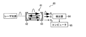
- FIG. 8 schematically shows an apparatus 60 for the cavity ring-down method.
- concave mirrors 62 and 63 are provided on both end faces of an elongated space 61, and the laser light is confined in the space 61 to lengthen the optical path of the laser light.
- Laser beams p 0 , p 1 ..., P M are extracted from the concave mirror 63 according to the number of reflections, detected by the detector 64, and the amount of gas absorption is calculated by the computer 65.
- the concave mirrors 62 and 63 the optical path of the laser beam can be lengthened, the amount of absorption by the gas to be measured increases, and the amount of absorption of the laser beam is inspected even with a small amount of gas. Can do.
- the present invention does not require a special cell, and does not require a long optical path of the laser beam, so that light absorption by a measurement object can be accurately in real time, and light using a laser absorption method can be inspected.
- An object of the present invention is to provide an absorption inspection apparatus and a light absorption inspection method.
- the present invention is an apparatus for irradiating a measurement object with pulsed laser light and inspecting absorption of the pulsed laser light when transmitted through the measurement object,
- a laser light source that emits a pulsed laser beam in accordance with a supplied drive pulse;
- a measurement unit that holds a measurement object and irradiates and transmits the pulsed laser light to the measurement object;
- a light receiving unit that receives the pulsed laser light transmitted through the measurement object and outputs a light reception signal;
- a pulse generator that generates a single rectangular pulse at a timing at which the signal level of the received light signal output from the light receiving unit crosses a set threshold; The generated rectangular pulse is supplied to the laser light source as the drive pulse for emission of pulse laser light from the laser light source, and a single pulse laser beam is supplied from the laser light source each time the drive pulse is supplied.
- a laser driver that emits light The laser driver is supplied with a driving pulse for start-up for starting emission of pulsed laser light, and after the laser light source emits pulsed laser light, the rectangular pulse is supplied from the pulse generator a plurality of times.
- the number of generations of the rectangular pulses is Accumulation of the generation timing of the rectangular pulse caused by the decrease in light intensity due to absorption of the pulsed laser light within the time between the rectangular pulse generated when the predetermined number is reached and the drive pulse for startup
- a control / processing unit that obtains a delay time and inspects the absorption of the pulsed laser light by the measurement object using the obtained accumulated delay time. To provide an absorbent inspection equipment.
- the measurement object is a gas contained in a gas
- the control / processing unit is configured to delay the generation timing of the rectangular pulse and the concentration of the gas when there is light absorption of the gas.
- a reference table showing the correspondence relationship between the gas and the gas concentration is calculated in advance from the obtained accumulated delay time using the reference table.
- the wavelength of the laser beam emitted from the laser light source is variably controlled by the control / processing unit, and the control / processing unit includes a first wavelength at which the cumulative delay time is maximized and a minimum at the first wavelength.
- the wavelength of 2 is set in the laser light source, and the difference between the accumulated delay time obtained at the first wavelength and the accumulated delay time obtained at the second wavelength is used. It is preferred to test for absorption.
- a beam splitter that separates the pulsed laser light emitted from the laser light source before entering the measurement unit; an intensity sensor that receives the separated pulsed laser light and detects the light intensity of the pulsed laser light; In order to compensate for fluctuations in the light intensity of the pulsed laser light, it is also preferable to include a threshold adjustment unit that adjusts the threshold based on the light intensity obtained by the intensity sensor. In that case, it is preferable that the said threshold value adjustment part sets the said threshold value so that it may be proportional to the said light intensity obtained with the said intensity sensor.
- the pulse laser beam is, for example, a laser beam having a wavelength in the infrared region.
- the present invention is a method for inspecting absorption of pulse laser light when the measurement object is irradiated with pulse laser light and transmitted through the measurement object, First pulse light is emitted from a laser light source by using a drive pulse supplied to emit pulsed laser light, and a light receiving signal is obtained by receiving pulsed laser light that has passed through a measurement object to be measured.
- Steps A second step of generating a single rectangular pulse at a timing at which the signal level of the obtained light reception signal crosses a set threshold; A third step of supplying the generated rectangular pulse to the laser light source as the drive pulse for emission of a single pulse laser beam; Repeatedly performing the first step, the second step and the third step; Within the time between the rectangular pulse when the number of generations of the generated rectangular pulse reaches a predetermined number and the drive pulse for start-up generated for the start of emission of the pulse laser beam, the pulse A fourth step of obtaining an accumulated delay time of the generation timing of the rectangular pulse caused by a decrease in light intensity due to absorption of laser light, and inspecting absorption of the pulse laser light by the measurement object using the accumulated delay time; A light absorption inspection method is provided.
- the first wavelength at which the accumulated delay time becomes maximum and the second wavelength at which the accumulated delay time becomes minimum are set in the laser light source, and in the fourth step, the first wavelength It is preferable to inspect infrared absorption of the measurement object using a difference between the accumulated delay time obtained at the wavelength and the accumulated delay time obtained at the second wavelength.
- the pulse laser beam emitted from the laser light source is separated before irradiating the measurement object, the separated pulse laser beam is received, and the light intensity of the pulse laser beam is detected.
- the method further includes a fifth step of adjusting the threshold based on the detected light intensity in order to compensate for fluctuations in the light intensity of the pulsed laser light.
- the pulse laser beam is, for example, a laser beam having a wavelength in the infrared region.
- the light intensity due to absorption of the pulsed laser beam is within the time between the rectangular pulse and the startup drive pulse when the number of rectangular pulses generated by the pulse generator reaches a predetermined number.
- the accumulated delay time of the generation timing of the rectangular pulse caused by the decrease in the frequency is obtained, and the absorption of light by the measurement object is inspected using this accumulated delay time. Therefore, it is possible to perform a highly accurate inspection as compared with the conventional case where it is obtained by changing the amplitude of the received light signal.
- a part of the pulsed laser beam is separated by a beam splitter, and the separated pulsed laser beam is measured by an intensity sensor. Based on the light intensity obtained by the intensity sensor. Since the threshold value used in the pulse generator is adjusted, an accurate delay time can be obtained and a highly accurate inspection can be performed even if there is a variation in the light intensity of the pulse laser beam every time it is emitted.
- FIG. 1 It is a schematic block diagram of one Embodiment of the light absorption inspection apparatus of this invention. It is a figure explaining the delay time obtained with the light absorption inspection apparatus of this invention.
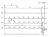
- (A) to (e) are timing charts of signals generated by the apparatus shown in FIG. It is a figure explaining the delay time of the rectangular pulse in the apparatus shown in FIG.
- FIG. 1 is a schematic configuration diagram of a trace gas inspection apparatus 10 by an infrared absorption method, which is an embodiment of a light absorption inspection apparatus of the present invention.
- the inspection apparatus 10 includes a laser light source 12, a measurement unit 14, an optical receiver 16, a received light signal amplifier 18, a comparator / signal generator (hereinafter simply referred to as a comparator) 20, a first coupler 22, a second coupler 24, and a drive signal.
- Amplifier 26 and control / processing unit 28 The laser light source 12, the measurement unit 14, the optical receiver 16, the light reception signal amplifier 18, the comparator 20, the first coupler 22, the second coupler 24, and the drive signal amplifier 26 are provided in a loop.
- the laser light source 12 is a light source that emits a single pulse laser beam having a wavelength in the infrared region in accordance with a single drive pulse supplied.
- a quantum cascade laser (QCL) light source that emits laser light of an arbitrary wavelength region from the infrared region to the terahertz region is used, and a laser oscillator set in a preset infrared region is preferably used. It is done. In the infrared region, there are many absorption lines of gas molecules to be inspected, and the absorption of various gas molecules can be measured.
- the laser light source 12 is configured such that the wavelength of the emitted laser light is variably controlled by the control / processing unit 28.
- the emission time of the pulse laser beam from the laser light source 12 is set to about 1 n to several tens of n seconds, for example.
- the measuring unit 14 is configured by a cylindrical container having a space for storing a gas containing a gas component to be inspected, and the pulse laser beam emitted from the laser light source 12 is transferred from one end of the cylindrical container to the other end. Light transmissive windows are provided at both ends so as to pass through.
- the cylindrical container does not need to be a sealed container, and is provided with a gas inlet 14a and a gas outlet 14b so that inspection can be performed in a state where a gas containing a gas component to be inspected flows.
- the reason why the flowing gas can be the inspection target is that the concentration of the gas component of the inspection target contained in the gas can be measured in substantially real time as will be described later.
- the length of the cylindrical container along the traveling direction of the laser light need not be as long as 1 to 15 m as in the conventional case, and may be several cm to 1 m.
- the optical receiver 16 is a portion that receives pulsed laser light transmitted through a gas containing a gas component to be inspected in a cylindrical container, and outputs a light reception signal.
- a photoconductive element having HgCdTe as a light receiving surface. (MCT element) is preferably used.
- the pulse laser beam that has been received by the optical receiver 16 and has passed through the measurement unit 14 has received light absorption of a gas component, and has a reduced light intensity.
- the light reception signal amplifier 18 amplifies the light reception signal output from the optical receiver 16.
- a known amplifier is used as the light receiving signal amplifier 18.
- the comparator 20 compares the amplified light reception signal output from the optical receiver 16 with a preset threshold value. When the signal level of the light reception signal crosses the set threshold value, the comparator 20 generates a rectangular pulse at the timing of the crossing. It corresponds to the pulse generator in the present invention.
- the first coupler 22 functions as a divider that distributes the rectangular pulse generated by the comparator 20, and a 3 dB coupler, a 6 dB coupler, or the like is used.
- One rectangular pulse distributed by the first coupler 22 is supplied to the control / processing unit 28.
- the other distributed rectangular pulse is supplied to the second coupler 24.
- the second coupler 24 passes through the rectangular pulse supplied from the first coupler 22 and supplies it to the drive signal amplifier 26. Further, the second coupler 24 connects the signal line from the control / processing unit 28 to the second coupler 24 in order to supply the drive pulse for rising supplied from the control / processing unit 28 to the drive signal amplifier 26.
- the first coupler 22 and the drive signal amplifier 26 are coupled to a signal line.
- the drive signal amplifier 26 amplifies the rectangular pulse and the startup drive pulse supplied from the second coupler 24 to a predetermined level, and supplies the amplified pulse to the laser light source 12 as a drive pulse of the laser light source 12.
- the drive signal amplifier 26 corresponds to the laser driver of the laser light source 12.
- the laser light source 12 emits a pulse laser beam in response to the drive pulse every time the drive pulse is supplied.
- the control / processing unit 28 is a part that controls the start and end of the gas component inspection and performs the light absorption inspection of the gas component, and is configured by a computer, for example.
- An RF switch (not shown) is provided in a part of the circuit shown in FIG. 1 forming the loop, and the control / processing unit 28 controls the RF switch to be turned OFF when the inspection is completed.
- the control / processing unit 28 generates a drive pulse for startup so that the pulsed laser beam starts to be emitted from the laser light source 12.
- control / processing unit 28 obtains the rectangular pulse supplied from the first coupler 22, and the rectangular pulse when the number of generations of the rectangular pulse generated by the comparator 20 reaches a predetermined number and the startup pulse
- the accumulated delay time due to light absorption that occurs within the elapsed time from the drive pulse is measured, and the infrared absorption of the gas component to be inspected is inspected using the measured accumulated delay time.
- the cumulative delay time is a time difference when the elapsed time when there is no light absorption is subtracted from the elapsed time when there is light absorption.
- the light intensity of the received light signal supplied to the comparator 20 is lower than that of the received light signal f a (t) when there is no infrared absorption.
- FIG. 2 shows a light reception signal when there is no infrared absorption (solid line) and a light reception signal when there is infrared absorption (dotted line).
- the comparator 20 When the amplified light reception signal crosses a preset threshold value, the comparator 20 generates a rectangular pulse at the timing of crossing, so that the light reception signal ⁇ ⁇ f a (t) (in which the light intensity has decreased due to infrared absorption.
- the generation timing of the rectangular pulse in ⁇ ⁇ 1) is delayed by ⁇ t.
- a startup drive pulse is generated by the control / processing unit 28 and a pulse laser beam is emitted from the laser light source 12
- a rectangular pulse is generated by the comparator 20 via a light reception signal generated by the optical receiver 16.
- the emission of the pulse laser light from the laser light source 12 and the rectangular pulse Is repeatedly generated.
- the number of rectangular pulse generation repetitions is N
- the timing of generating the rectangular pulse is when there is no light absorption. Compared to the total, N ⁇ t is delayed.
- This N ⁇ t is the accumulated delay time.
- the number of generated pulses is counted using a counter circuit (not shown).
- the Nth rectangular pulse is supplied to the control / processing unit 28.
- the first coupler 22 is set so that the rectangular pulse is sent to the second coupler 24 when the count result does not reach the Nth time.
- the control / processing unit 28 measures the accumulated delay time of the timing at which the Nth rectangular pulse is generated, which is generated within the elapsed time between the Nth rectangular pulse and the drive pulse for start-up. One delay time is obtained from the delay time, the infrared absorption of the gas component is inspected, and the concentration of the gas component is further obtained.
- the elapsed time T ′ when it is assumed that there is no infrared absorption includes the transmission time of the received light signal and the rectangular pulse on the signal line in addition to the time during which the pulse laser beam passes through the light receiving unit 14.
- control / processing unit 28 can perform the following processing instead of the above processing.
- the control / processing unit 28 measures the wavelength of the laser light at the first wavelength at which the accumulated delay time is maximized and the second wavelength at which the accumulated delay time is minimized, and at the first wavelength at this time
- the difference between the accumulated delay time (maximum accumulated delay time) and the accumulated delay time at the second wavelength (minimum accumulated delay time) is the original accumulated delay time, and one rectangular pulse generated from this accumulated delay time is generated. From the timing delay time ⁇ t, it is also possible to inspect the infrared absorption of the gas component by using the above-described reference table.
- the accumulated delay time when absorbing infrared rays and the accumulated delay time when not absorbing infrared rays are obtained by using the change in the wavelength of the pulse laser beam.
- the wavelength at which the cumulative delay time is maximized and the wavelength at which the accumulated delay time is minimized are known wavelengths when the gas component to be measured is known.
- FIG. 3 is a timing chart according to examples of various signals obtained by the inspection apparatus 10.
- FIG. 3A shows a frequency-divided signal of the clock signal used in the control / processing unit 28, and
- FIG. 3B shows a drive pulse for start-up generated by the control / processing unit 28.
- the drive pulse for start-up is generated in synchronization with the frequency-divided signal of the clock signal shown in FIG.
- FIG. 3C shows the amplified light reception signal output from the optical receiver 16
- FIG. 3D shows the rectangular pulse generated by the comparator 20 when there is no light absorption
- FIG. A rectangular pulse generated by the comparator 20 when there is light absorption is shown.
- the period of the frequency-divided signal is T c, and one period when there is no light absorption is T p .
- the control / processing unit 26 calculates a time ⁇ t from the rising edge of the N′th pulse to the rising edge of the first rectangular pulse (Nth rectangular pulse) generated thereafter. Measure using clock signal pulses.
- the elapsed time T is obtained by adding the time (N′ ⁇ 1) ⁇ T c between the rising drive pulse shown in FIG. 3B and the rising edge of the N′th pulse to the time ⁇ t.
- the accumulated delay time N ⁇ ⁇ t is obtained by subtracting the elapsed time T ′ when there is no light absorption from the elapsed time T.
- a delay time ⁇ t is obtained, and using this delay time ⁇ t, the infrared absorption of the gas component is inspected to obtain the concentration of the gas component.
- the concentration of the gas component to be inspected is obtained using the delay time ⁇ t and a reference table representing the relationship between the delay time stored in advance and the concentration of the gas component.
- FIG. 4 is a diagram explaining the above contents in an easy-to-understand manner.
- the pulse laser beam, the light reception signal, and the rectangular pulse move on the torus surface 29 shown in FIG. 4, when the circular cross section of the torus surface 29 makes one round, it moves spirally so that a delay time ⁇ t occurs. . In this way, the cumulative delay time N ⁇ ⁇ t when N rounds the circular section is obtained.
- the control / processing unit 28 inspects the light absorption of the gas component using the information on the delay in the generation timing of the rectangular pulse generated by the decrease in the amplitude of the received light signal. This is because measuring the accumulated delay time N ⁇ t is more accurate than measuring the decrease in the light intensity of the pulsed laser beam due to absorption. For example, by setting N to several 10000 times or more, it is possible to inspect extremely highly accurate infrared absorption. By increasing the number of N, even if there is a variation in the timing at which rectangular pulses are generated, the average value of this variation approaches 0 as the number of N increases, so a single delay with high accuracy The time ⁇ t can be obtained.
- a signal passes through the same optical path many times via an electric circuit.
- one pulsed laser beam passes through the cylindrical container in the measurement unit 14 only once.
- the light beam of the laser beam does not expand due to the increase in the optical path length, and the desired position can be passed by the laser beam narrowed down.
- the length of the laser beam in the measuring unit 14 in the traveling direction is several centimeters, the amount of light absorbed by one pulsed laser beam by a light gas component (concentration of about ppm) is small. It is.
- the difference between the light reception signal output from the optical receiver 16 at this time and the light reception signal when there is no light absorption cannot be detected by a 12 to 16-bit AD converter. Even if the averaging process is performed, the difference cannot be obtained. This is because the change in the received light signal due to light absorption is so small that it cannot be captured within the effective digit range of the AD converter.
- the present invention is greatly different from the conventional method in that the amount of light absorption can be accurately measured by using time measurement with high accuracy without using the measurement of the amplitude of the received light signal as in the prior art.
- the control / processing unit 28 measures the time ⁇ t by using an accurate clock signal pulse in the control / processing unit 28.
- the time ⁇ t can also be measured as follows. . That is, the triangular wave signal is started at the rise timing of the N′th pulse shown in FIG. 3A, and the signal level of the triangular wave signal when the Nth rectangular pulse rises is used, and FIG. The indicated time ⁇ t is measured.
- the elapsed time T may be obtained by adding the time (N′ ⁇ 1) ⁇ T c to the measured time ⁇ t.
- the apparatus configuration as shown in FIG. By adding, variations in light intensity can be compensated. That is, a beam splitter 30 that separates the pulsed laser light emitted from the laser light source 12 before entering the measuring unit 14, and an intensity sensor 32 that receives the separated pulsed laser light and detects the light intensity of the pulsed laser light. In order to compensate for fluctuations in the light intensity of the pulsed laser light, a gain adjuster (threshold adjustment unit) 34 that adjusts the threshold used in the comparator 20 based on the light intensity obtained by the intensity sensor 32 is provided. Good.
- the pulse laser beam is separated using the beam splitter 30, the light intensity of one of the separated pulse laser lights is monitored by the intensity sensor 32, and the light intensity information obtained by the intensity sensor 32 is used for the comparator 20. Adjust the threshold.
- the gain adjuster 34 sets a threshold value so as to be proportional to the light intensity obtained by the intensity sensor 32. Thereby, even if the light intensity of the pulsed laser light changes with each emission, the comparator 20 can keep the delay time constant.
- the noise component included in the pulse laser beam emitted from the laser light source 12 is larger than the noise component included in the light receiving signal amplifier 18 and the drive signal amplifier 26, the noise component included in the pulse laser beam.
- the comparator 20 can keep the delay time constant.
- the light intensity of the pulsed laser light is the same as the first wavelength. It may also change at the second wavelength. In this case, as described above, it is preferable to adjust the threshold value used for the comparator 20 by using the light intensity information of the pulsed laser light.
- a single pulse laser beam is converted into a laser light source 12 using a drive pulse for start-up (see FIG. 3B) generated for starting emission of the pulse laser beam. And receiving a pulsed laser beam that has passed through a gas containing a gas component to be measured, and obtains a light reception signal.
- a single rectangular pulse (see FIG. 3D) is generated at a timing when the signal level of the obtained light reception signal crosses the set threshold value. Thereafter, the generated rectangular pulse is amplified by the drive signal amplifier 26 and then supplied to the laser light source 12 as a drive pulse for emitting pulsed laser light.
- the pulse laser beam is repeatedly emitted from the laser light source 12, and a rectangular pulse when the number of generated rectangular pulses reaches N times and a drive pulse for start-up shown in FIG.
- the accumulated delay time N ⁇ t of the timing of generating the rectangular pulse occurring within the interval is obtained, and the infrared absorption of the gas component is inspected using this accumulated delay time.
- the emission time of the pulse laser beam is 1 ns
- the period for which the signal goes around the inspection apparatus 10 is 10 ns
- N is 10 6 times
- the accumulated delay time N • 10 ms is required to measure ⁇ t.
- the pulse laser beam has a total optical path of 1 km, and passes through an optical path length equal to or longer than that of the conventional measuring method. Become. That is, since the light absorption amount at the optical path length of 1 km can be known from the measurement time of 10 milliseconds, the infrared absorption amount of the gas component contained in the gas can be inspected in substantially real time.
- the present invention in addition to being applied to an inspection apparatus for trace gases by the infrared absorption method, by examining the absorption of infrared rays, it is possible to detect molecular species, radical species, and solid surfaces in the cross section of plasma or combustion flame that absorbs infrared rays. It is also possible to obtain the distribution of specific molecular species and molecular groups that absorb infrared rays.
- the present invention can be suitably applied to local infrared absorption measurement such as a scanning near-field microscope shown in FIG.
- FIG. 6 is a schematic configuration diagram of a scanning near-field microscope (hereinafter referred to as a microscope) 40.
- the microscope 40 includes a laser light source 42, a prism 44, an optical fiber 45, a PZT scanning mechanism 46, a photodetector 47, a loop circuit 48, and a control / processing unit 49.
- the laser light source 42 is a light source that emits pulsed laser light in the infrared region.
- the prism 44 is configured to completely reflect the laser light from the laser light source 12 on the bottom surface on which the measurement object M is placed.
- the optical fiber 45 collects the light that has passed through the measurement object M out of the evanescent light leaking from the bottom surface of the prism 44 and sends it to the photodetector 47.
- the PZT scanning mechanism 46 moves the tip of the optical fiber 45 along the bottom surface of the prism 44 so that the optical fiber 45 collects the transmitted light of the evanescent light at each position of the measurement object M placed on the bottom surface of the prism 44. It is a moving mechanism that moves and scans.
- the photodetector 47 is a sensor that converts light transmitted from the optical fiber 45 into a light reception signal. The obtained light reception signal is sent to the loop circuit 48.
- the loop circuit 48 includes circuits similar to the received light signal amplifier 18, the comparator 20, the first coupler 22, the second coupler 24, and the drive signal amplifier 26 shown in FIG. 1, and the received light signal obtained by the photodetector 47. However, a rectangular pulse is generated at a timing that crosses a set threshold value, and the rectangular pulse is amplified and supplied to the laser light source 42.
- the control / processing unit 49 exhibits the same function as the control / processing unit 28 shown in FIG. Therefore, the control / processing unit 49 can obtain the delay time ⁇ t of the rectangular pulse, and can obtain the infrared absorption amount of the measuring object M.
- the infrared absorption distribution can be obtained by obtaining the infrared absorption while scanning with the PZT scanning mechanism 46. Thereby, the control / processing unit 49 can obtain the distribution (image) of the specific substance that absorbs infrared rays contained in the measurement object M, and functions as the microscope 40. Thus, it is possible to know the distribution of a specific substance that absorbs infrared rays.
Landscapes
- Physics & Mathematics (AREA)
- Spectroscopy & Molecular Physics (AREA)
- General Physics & Mathematics (AREA)
- General Health & Medical Sciences (AREA)
- Health & Medical Sciences (AREA)
- Life Sciences & Earth Sciences (AREA)
- Chemical & Material Sciences (AREA)
- Analytical Chemistry (AREA)
- Biochemistry (AREA)
- Immunology (AREA)
- Pathology (AREA)
- Optics & Photonics (AREA)
- Investigating Or Analysing Materials By Optical Means (AREA)
Abstract
Description
図8に示す装置60でも、図7に示す装置50と同様に、反射率の高い凹面鏡を作製することは難しい。さらに、反射率の高い凹面鏡を用いるので、レーザ光を端面から細長い空間内に導入するには、出力の大きなレーザ発生装置が必要となる等の課題がある。
供給される駆動パルスに応じて、パルスレーザ光を出射するレーザ光源と、
測定対象物を保持し、前記パルスレーザ光を測定対象物に照射し透過させる測定部と、
前記測定対象物を透過したパルスレーザ光を受光し、受光信号を出力する受光部と、
前記受光部から出力された受光信号の信号レベルが、設定された閾値を横切るタイミングで、単一の矩形パルスを生成するパルス生成器と、
生成された前記矩形パルスを、前記レーザ光源におけるパルスレーザ光の出射のための前記駆動パルスとして前記レーザ光源に供給し、該駆動パルスの供給のたびに、前記レーザ光源から単一のパルスレーザ光を出射させるレーザドライバと、
前記レーザドライバに、パルスレーザ光の出射開始のための立ち上げ用の駆動パルスが供給されて前記レーザ光源がパルスレーザ光を出射した後、前記パルス生成器から前記矩形パルスが複数回供給されることにより、前記レーザ光源が単一のパルスレーザ光を複数回出射し、前記パルス生成器で生成される前記矩形パルスの生成回数が所定の数に達したとき、前記矩形パルスの生成回数が前記所定の数に達したときに生成された矩形パルスと前記立ち上げ用の駆動パルスとの間の時間内に、パルスレーザ光の吸収による光強度の低下によって生じる前記矩形パルスの生成のタイミングの累積遅延時間を求め、求めた前記累積遅延時間を用いて、測定対象物によるパルスレーザ光の吸収を検査する制御・処理部と、を有することを特徴とする光吸収検査装置を提供する。
また、前記レーザ光源が出射するレーザ光の波長は、前記制御・処理部によって可変に制御され、前記制御・処理部は、前記累積遅延時間が最大となる第1の波長と、最小となる第2の波長を前記レーザ光源に設定し、前記第1の波長において求められる前記累積遅延時間と、前記第2の波長において求められる前記累積遅延時間との差分を用いて、測定対象物による赤外線の吸収を検査することが好ましい。
前記パルスレーザ光は、例えば、波長が赤外領域にあるレーザ光である。
パルスレーザ光の出射ために供給される駆動パルスを用いて、前記パルスレーザ光をレーザ光源から出射させ、測定対象の測定対象物を透過したパルスレーザ光を受光して受光信号を得る第1のステップと、
得られた受光信号の信号レベルが設定された閾値を横切るタイミングで、単一の矩形パルスを生成させる第2のステップと、
生成された前記矩形パルスを、単一のパルスレーザ光の出射のための前記駆動パルスとして前記レーザ光源に供給する第3のステップと、
前記第1のステップ、前記第2のステップおよび前記第3のステップを繰り返し行い、
前記生成される矩形パルスの生成回数が所定の数に達したときの矩形パルスと、前記パルスレーザ光の出射開始のために生成された立ち上げ用の駆動パルスとの間の時間内に、パルスレーザ光の吸収による光強度の低下によって生じる前記矩形パルスの生成のタイミングの累積遅延時間を求め、この累積遅延時間を用いて、測定対象物によるパルスレーザ光の吸収を検査する第4のステップと、を有することを特徴とする光吸収検査方法を提供する。
前記パルスレーザ光は、例えば、波長が赤外領域にあるレーザ光である。
また、パルスレーザ光が、測定部に入射する前に、その一部分をビームスプリッタで分離させることにより、分離したパルスレーザ光を強度センサで測定し、この強度センサで得られた光強度に基づいて、パルス生成器で用いる閾値を調整するので、パルスレーザ光の光強度に出射の度にばらつきがあっても、正確な遅延時間を求めることができ、精度の高い検査を行うことができる。
図1は、本発明の光吸収検査装置の一実施形態である、赤外線吸収法による微量ガスの検査装置10の概略構成図である。
検査装置10は、レーザ光源12、測定部14、光受信器16、受光信号用増幅器18、コンパレータ・信号生成器(以降、単にコンパレータという)20、第1カプラー22、第2カプラー24、駆動信号用増幅器26、および制御・処理部28を有する。レーザ光源12、測定部14、光受信器16、受光信号用増幅器18、コンパレータ20、第1カプラー22、第2カプラー24、駆動信号用増幅器26の構成部品がループ状に設けられている。
また、筒状容器の、レーザ光の進行方向に沿った長さも、従来のように1~15mと長い必要はなく、数cm~1mであってもよい。
コンパレータ20は、光受信器16から出力され増幅された受光信号を、予め設定された閾値と比較し、この受光信号の信号レベルが設定された閾値を横切るとき、この横切るタイミングで、矩形パルスを生成するもので、本発明におけるパルス生成器に対応する。
第2カプラー24は、第1カプラー22から供給された矩形パルスをスルーして、駆動信号用増幅器26に供給する。さらに、第2カプラー24は、制御・処理部28から供給される立ち上がり用の駆動パルスを駆動信号用増幅器26に供給するために、制御・処理部28からの信号線路を、第2カプラー24を介して、第1カプラー22と駆動信号用増幅器26とを接続する信号線路に結合させる。
制御・処理部28は、レーザ光源12からパルスレーザ光が出射を開始するように、立ち上げ用の駆動パルスを生成する。また、制御・処理部28は、第1カプラー22から供給された矩形パルスを得て、コンパレータ20で生成される矩形パルスの生成回数が所定の数に達したときの矩形パルスと立ち上げ用の駆動パルスとの間の経過時間内に発生する、光吸収による累積遅延時間を計測し、この計測した累積遅延時間を用いて、検査対象のガス成分の赤外線の吸収を検査する。累積遅延時間は、光吸収があるときの上記経過時間から、光吸収がないときの上記経過時間を差し引いた時の時間差をいう。
図3(a)は、制御・処理部28で用いられるクロック信号の分周信号を、図3(b)は、制御・処理部28で生成される立ち上げ用の駆動パルスを示している。立ち上げ用の駆動パルスは、図3(a)に示すクロック信号の分周信号に同期して生成されている。図3(c)は、光受信器16から出力され増幅された受光信号を、図3(d)は、光吸収がないときのコンパレータ20で生成される矩形パルスを、図3(e)は、光吸収があるときのコンパレータ20で生成される矩形パルスを、示している。
すなわち、レーザ光源12から出射したパルスレーザ光を、測定部14に入射する前に分離させるビームスプリッタ30と、分離したパルスレーザ光を受光し、パルスレーザ光の光強度を検知する強度センサ32と、パルスレーザ光の光強度の揺らぎを補償するために、強度センサ32で得られた光強度に基づいて、コンパレータ20に用いる閾値を調整するゲイン調整器(閾値調整部)34と、を設けるとよい。
実際、レーザ光源12から出射されるパルスレーザ光に含まれるノイズ成分が、受光信号用増幅器18、駆動信号用増幅器26にて含まれるノイズ成分に比べて大きいため、パルスレーザ光に含まれるノイズ成分により、パルスレーザ光の光強度が変化しても、コンパレータ20では遅延時間を一定に保つことができる。
また、上述したように、第1の波長における累積遅延時間と第2の波長における累積遅延時間との差分を本来の累積遅延時間として用いるとき、パルスレーザ光の光強度が、第1の波長と第2の波長において変化する場合もある。この場合、上記のように、パルスレーザ光の光強度の情報を用いて、コンパレータ20に用いる閾値を調整することが好ましい。
次に、得られた受光信号の信号レベルが、設定された閾値を横切るタイミングで、単一の矩形パルス(図3(d)参照)を生成させる。
この後、生成された矩形パルスを駆動用信号増幅器26で増幅した後、パルスレーザ光の出射のための駆動パルスとしレーザ光源12に供給する。
このレーザ光源12からのパルスレーザ光の出射を繰り返し行い、生成される矩形パルスの生成回数がN回に達したときの矩形パルスと、図3(b)に示す立ち上げ用の駆動パルスとの間の時間内で生じる矩形パルスの生成のタイミングの累積遅延時間NΔtを求め、この累積遅延時間を用いて、ガス成分の赤外線の吸収を検査する。
顕微鏡40は、レーザ光源42、プリズム44と、光ファイバ45と、PZT走査機構46と、光検出器47と、ループ回路48と、制御・処理部49とを有して構成される。
プリズム44は、レーザ光源12からのレーザ光を、測定対象物Mを載置する底面で完全反射するように構成されている。
光ファイバ45は、プリズム44の底面から漏れ出るエバネッセント光のうち測定対象物Mを透過した光を収集し、光検出器47に送る。
PZT走査機構46は、プリズム44の底面に載置した測定対象物Mの各位置におけるエバネッセント光の透過光を光ファイバ45が収集するように、プリズム44の底面に沿って光ファイバ45の先端を移動し走査する移動機構である。
光検出器47は、光ファイバ45から送られる光を受光信号に変換するセンサである。得られた受光信号は、ループ回路48に送られる。
12,42 レーザ光源
14 測定部
16 光受信器
18 受光信号用増幅器
20 コンパレータ・信号生成器
22 第1カプラー
24 第2カプラー
26 駆動信号用増幅器
28,49 制御・処理部
29 トーラス面
30 ビームスプリッタ
32 強度センサ
34 ゲイン調整器
40 走査型近接場顕微鏡
44 プリズム
45 充ファイバ
46 PZT走査機構
47 光検出器
48 ループ回路
50,60 装置
51 セル
52 鏡
53,54 検出器
61 空間
62,63 凹面鏡
64 検出器
Claims (10)
- パルスレーザ光を測定対象物に照射し、測定対象物を透過したときのパルスレーザ光の吸収を検査する装置であって、
供給される駆動パルスに応じて、パルスレーザ光を出射するレーザ光源と、
測定対象物を保持し、前記パルスレーザ光を測定対象物に照射し透過させる測定部と、
前記測定対象物を透過したパルスレーザ光を受光し、受光信号を出力する受光部と、
前記受光部から出力された受光信号の信号レベルが、設定された閾値を横切るタイミングで、単一の矩形パルスを生成するパルス生成器と、
生成された前記矩形パルスを、前記レーザ光源におけるパルスレーザ光の出射のための前記駆動パルスとして前記レーザ光源に供給し、該駆動パルスの供給のたびに、前記レーザ光源から単一のパルスレーザ光を出射させるレーザドライバと、
前記レーザドライバに、パルスレーザ光の出射開始のための立ち上げ用の駆動パルスが供給されて前記レーザ光源がパルスレーザ光を出射した後、前記パルス生成器から前記矩形パルスが複数回供給されることにより、前記レーザ光源が単一のパルスレーザ光を複数回出射し、前記パルス生成器で生成される前記矩形パルスの生成回数が所定の数に達したとき、前記矩形パルスの生成回数が前記所定の数に達したときに生成された矩形パルスと前記立ち上げ用の駆動パルスとの間の時間内に、パルスレーザ光の吸収による光強度の低下によって生じる前記矩形パルスの生成のタイミングの累積遅延時間を求め、求めた前記累積遅延時間を用いて、測定対象物によるパルスレーザ光の吸収を検査する制御・処理部と、を有することを特徴とする光吸収検査装置。 - 前記測定対象物は、気体に含まれるガスであり、
前記制御・処理部は、前記ガスの光吸収があるときの、前記矩形パルスの生成のタイミングの遅延時間と、前記ガスの濃度との対応関係を表した参照テーブルを予め備え、この参照テーブルを用いて、求めた前記累積遅延時間から前記ガスの濃度を算出する請求項1に記載の光吸収検査装置。 - 前記レーザ光源が出射するレーザ光の波長は、前記制御・処理部によって可変に制御され、
前記制御・処理部は、前記累積遅延時間が最大となる第1の波長と、最小となる第2の波長を前記レーザ光源に設定し、前記第1の波長において求められる前記累積遅延時間と、前記第2の波長において求められる前記累積遅延時間との差分を用いて、測定対象物による赤外線の吸収を検査する請求項1または2に記載の光吸収検査装置。 - 前記レーザ光源から出射したパルスレーザ光を、前記測定部に入射する前に分離させるビームスプリッタと、
分離したパルスレーザ光を受光し、パルスレーザ光の光強度を検知する強度センサと、
前記パルスレーザ光の光強度の揺らぎを補償するために、前記強度センサで得られた光強度に基づいて、前記閾値を調整する閾値調整部と、を有する請求項1~3のいずれか1項に記載の光吸収検査装置。 - 前記閾値調整部は、前記強度センサで得られる前記光強度に比例するように、前記閾値を設定する請求項4に記載の光吸収検査装置。
- 前記パルスレーザ光は、波長が赤外領域にあるレーザ光である請求項1~5のいずれか1項に記載の光吸収検査装置。
- パルスレーザ光を測定対象物に照射し、測定対象物を透過したときのパルスレーザ光の吸収を検査する方法であって、
パルスレーザ光の出射ために供給される駆動パルスを用いて、前記パルスレーザ光をレーザ光源から出射させ、測定対象の測定対象物を透過したパルスレーザ光を受光して受光信号を得る第1のステップと、
得られた受光信号の信号レベルが設定された閾値を横切るタイミングで、単一の矩形パルスを生成させる第2のステップと、
生成された前記矩形パルスを、単一のパルスレーザ光の出射のための前記駆動パルスとして前記レーザ光源に供給する第3のステップと、
前記第1のステップ、前記第2のステップおよび前記第3のステップを繰り返し行い、
前記生成される矩形パルスの生成回数が所定の数に達したときの矩形パルスと、前記パルスレーザ光の出射開始のために生成された立ち上げ用の駆動パルスとの間の時間内に、パルスレーザ光の吸収による光強度の低下によって生じる前記矩形パルスの生成のタイミングの累積遅延時間を求め、この累積遅延時間を用いて、測定対象物によるパルスレーザ光の吸収を検査する第4のステップと、を有することを特徴とする光吸収検査方法。 - 前記第1のステップにおいて、前記累積遅延時間が最大となる第1の波長と、最小となる第2の波長を前記レーザ光源に設定し、
前記第4のステップにおいて、前記第1の波長において求められる前記累積遅延時間と、前記第2の波長において求められる前記累積遅延時間との差分を用いて、測定対象物の赤外線の吸収を検査する請求項7に記載の光吸収検査方法。 - 前記第1のステップにおいて、前記レーザ光源から出射したパルスレーザ光を、測定対象物に照射する前に分離し、
分離した前記パルスレーザ光を受光し、パルスレーザ光の光強度を検知し、前記パルスレーザ光の光強度の揺らぎを補償するために、前記検知した光強度に基づいて、前記閾値を調整する第5のステップをさらに有する請求項7または8に記載の光吸収検査方法。 - 前記パルスレーザ光は、波長が赤外領域にあるレーザ光である請求項7~9のいずれか1項に記載の光吸収検査方法。
Priority Applications (3)
| Application Number | Priority Date | Filing Date | Title |
|---|---|---|---|
| DE112009001711T DE112009001711T5 (de) | 2008-07-22 | 2009-07-21 | Vorrichtung zur Messung von Infrarotabsorption und Verfahren zur Messung von Infrarotabsorption |
| US13/055,439 US8645081B2 (en) | 2008-07-22 | 2009-07-21 | Device and method of examining absorption of infrared radiation |
| JP2009531505A JP4392850B1 (ja) | 2008-07-22 | 2009-07-21 | 赤外線吸収検査装置および赤外線吸収検査方法 |
Applications Claiming Priority (2)
| Application Number | Priority Date | Filing Date | Title |
|---|---|---|---|
| JP2008-188288 | 2008-07-22 | ||
| JP2008188288 | 2008-07-22 |
Publications (1)
| Publication Number | Publication Date |
|---|---|
| WO2010010684A1 true WO2010010684A1 (ja) | 2010-01-28 |
Family
ID=41570154
Family Applications (1)
| Application Number | Title | Priority Date | Filing Date |
|---|---|---|---|
| PCT/JP2009/003398 Ceased WO2010010684A1 (ja) | 2008-07-22 | 2009-07-21 | 赤外線吸収検査装置および赤外線吸収検査方法 |
Country Status (4)
| Country | Link |
|---|---|
| US (1) | US8645081B2 (ja) |
| JP (1) | JP4392850B1 (ja) |
| DE (1) | DE112009001711T5 (ja) |
| WO (1) | WO2010010684A1 (ja) |
Cited By (3)
| Publication number | Priority date | Publication date | Assignee | Title |
|---|---|---|---|---|
| JP2011017622A (ja) * | 2009-07-09 | 2011-01-27 | Mitsui Eng & Shipbuild Co Ltd | 電磁波測定装置、及び電磁波測定方法 |
| CN105675531A (zh) * | 2016-03-22 | 2016-06-15 | 南京大学 | 一种气体太赫兹吸收光谱的检测装置 |
| JP2016192423A (ja) * | 2015-03-30 | 2016-11-10 | パイオニア株式会社 | 光伝導素子及び計測装置 |
Families Citing this family (7)
| Publication number | Priority date | Publication date | Assignee | Title |
|---|---|---|---|---|
| JP5950593B2 (ja) * | 2012-02-02 | 2016-07-13 | 光トライオード株式会社 | 閉鎖系信号伝搬装置、およびそれを含む吸光分析装置 |
| RU2614657C2 (ru) * | 2012-05-02 | 2017-03-28 | Вилко Аг | Способ обнаружения газа-пропеллента |
| US9325334B2 (en) * | 2013-06-12 | 2016-04-26 | Texas Instruments Incorporated | IC, process, device generating frequency reference from RF gas absorption |
| US9500580B1 (en) | 2015-06-04 | 2016-11-22 | General Electric Company | Gas detector and method of detection |
| JP2017015736A (ja) * | 2016-10-19 | 2017-01-19 | ヴィルコ・アーゲー | プロペラントガスを検出する方法 |
| IL260523B (en) * | 2018-07-10 | 2021-12-01 | Vayu Sense Ag | Apparatus for monitoring gas molecules in fermentation based processes |
| US11137282B2 (en) * | 2019-09-30 | 2021-10-05 | Asahi Kasei Microdevices Corporation | Optical concentration measurement device comprising a light receiving unit with a rectangular light receiving surface |
Citations (4)
| Publication number | Priority date | Publication date | Assignee | Title |
|---|---|---|---|---|
| JP2003247941A (ja) * | 2002-02-26 | 2003-09-05 | National Institute Of Advanced Industrial & Technology | 混合ガスの各ガス濃度を測定するための方法及び装置 |
| JP2005157601A (ja) * | 2003-11-25 | 2005-06-16 | Canon Inc | 電磁波による積層状物体計数装置及び計数方法 |
| JP2005535411A (ja) * | 2002-08-14 | 2005-11-24 | オプテイスカン・バイオメデイカル・コーポレーシヨン | 体液中の分析物濃度の体外決定用のデバイスと方法 |
| JP2006105720A (ja) * | 2004-10-04 | 2006-04-20 | Topcon Corp | 光画像計測装置 |
Family Cites Families (5)
| Publication number | Priority date | Publication date | Assignee | Title |
|---|---|---|---|---|
| DE2633042A1 (de) * | 1976-07-26 | 1978-01-26 | Nishi Nippon Denki Co | Zielanordnung fuer impulslichtstrahl mit kreuzweise angeordneten und gruppierten phototransistoren |
| JPH0315742A (ja) * | 1989-03-23 | 1991-01-24 | Anritsu Corp | ガス検出装置 |
| US5317376A (en) * | 1992-12-03 | 1994-05-31 | Litton Systems, Inc. | Solid state pulsed coherent laser radar for short range velocimetry applications |
| US6191861B1 (en) * | 1999-02-13 | 2001-02-20 | Mcbranch Duncan W. | Femtosecond chirp-free transient absorption method and apparatus |
| SG99872A1 (en) * | 1999-10-26 | 2003-11-27 | Mitsubishi Heavy Ind Ltd | Method and apparatus for laser analysis of dioxins |
-
2009
- 2009-07-21 WO PCT/JP2009/003398 patent/WO2010010684A1/ja not_active Ceased
- 2009-07-21 JP JP2009531505A patent/JP4392850B1/ja not_active Expired - Fee Related
- 2009-07-21 US US13/055,439 patent/US8645081B2/en not_active Expired - Fee Related
- 2009-07-21 DE DE112009001711T patent/DE112009001711T5/de not_active Withdrawn
Patent Citations (4)
| Publication number | Priority date | Publication date | Assignee | Title |
|---|---|---|---|---|
| JP2003247941A (ja) * | 2002-02-26 | 2003-09-05 | National Institute Of Advanced Industrial & Technology | 混合ガスの各ガス濃度を測定するための方法及び装置 |
| JP2005535411A (ja) * | 2002-08-14 | 2005-11-24 | オプテイスカン・バイオメデイカル・コーポレーシヨン | 体液中の分析物濃度の体外決定用のデバイスと方法 |
| JP2005157601A (ja) * | 2003-11-25 | 2005-06-16 | Canon Inc | 電磁波による積層状物体計数装置及び計数方法 |
| JP2006105720A (ja) * | 2004-10-04 | 2006-04-20 | Topcon Corp | 光画像計測装置 |
Cited By (3)
| Publication number | Priority date | Publication date | Assignee | Title |
|---|---|---|---|---|
| JP2011017622A (ja) * | 2009-07-09 | 2011-01-27 | Mitsui Eng & Shipbuild Co Ltd | 電磁波測定装置、及び電磁波測定方法 |
| JP2016192423A (ja) * | 2015-03-30 | 2016-11-10 | パイオニア株式会社 | 光伝導素子及び計測装置 |
| CN105675531A (zh) * | 2016-03-22 | 2016-06-15 | 南京大学 | 一种气体太赫兹吸收光谱的检测装置 |
Also Published As
| Publication number | Publication date |
|---|---|
| DE112009001711T5 (de) | 2011-06-09 |
| JPWO2010010684A1 (ja) | 2012-01-05 |
| US8645081B2 (en) | 2014-02-04 |
| JP4392850B1 (ja) | 2010-01-06 |
| US20110130973A1 (en) | 2011-06-02 |
Similar Documents
| Publication | Publication Date | Title |
|---|---|---|
| JP4392850B1 (ja) | 赤外線吸収検査装置および赤外線吸収検査方法 | |
| US8735768B2 (en) | Laser welding apparatus | |
| JP5357531B2 (ja) | 情報取得装置及び情報取得方法 | |
| US20190025203A1 (en) | Optical absorption spectroscopy based gas analyzer systems and methods | |
| US10101208B2 (en) | Apparatus and method for measuring the concentration of trace gases by SCAR spectroscopy | |
| US7593099B2 (en) | Method and device for configuration examination | |
| JP5992147B2 (ja) | テラヘルツ波を用いた検査装置及び検査方法 | |
| US7817270B2 (en) | Nanosecond flash photolysis system | |
| US8097859B2 (en) | Oxygen concentration measuring device | |
| CN108827911A (zh) | 一种显微共振激光诱导击穿光谱检测方法及系统 | |
| CN111122500A (zh) | 一种基于相干探测方法的气体浓度遥感探测装置和方法 | |
| JP2014194344A (ja) | テラヘルツ波を用いた測定方法 | |
| JP2001141567A (ja) | 赤外分光装置 | |
| JP2001021503A (ja) | テラヘルツ帯複素誘電率測定装置 | |
| JP6538191B2 (ja) | 計測装置、計測方法及びコンピュータプログラム | |
| CN111208084A (zh) | 一种基于相干探测方法的光纤气体浓度遥感探测装置和方法 | |
| JP6061197B2 (ja) | テラヘルツ波を用いた異物検査装置及びその方法 | |
| US20150241348A1 (en) | Information acquiring apparatus and information acquiring method | |
| JP5256136B2 (ja) | 電磁波測定装置、及び電磁波測定方法 | |
| AU2012211024A1 (en) | An emission spectrometer and method of operation | |
| JP4662831B2 (ja) | 試料分析装置 | |
| KR101348917B1 (ko) | 씨앗주입레이저를 사용하는 방사능물질 원격 탐지를 위한 라이다 장치 | |
| JP3648019B2 (ja) | 少数キャリアのライフタイム測定装置 | |
| JP2005214954A (ja) | 電磁波発生方法及び装置 | |
| JPH1123450A (ja) | ガス濃度検知方法及び装置 |
Legal Events
| Date | Code | Title | Description |
|---|---|---|---|
| ENP | Entry into the national phase |
Ref document number: 2009531505 Country of ref document: JP Kind code of ref document: A |
|
| 121 | Ep: the epo has been informed by wipo that ep was designated in this application |
Ref document number: 09800200 Country of ref document: EP Kind code of ref document: A1 |
|
| WWE | Wipo information: entry into national phase |
Ref document number: 13055439 Country of ref document: US |
|
| RET | De translation (de og part 6b) |
Ref document number: 112009001711 Country of ref document: DE Date of ref document: 20110609 Kind code of ref document: P |
|
| 122 | Ep: pct application non-entry in european phase |
Ref document number: 09800200 Country of ref document: EP Kind code of ref document: A1 |