WO2010007785A1 - 照明装置 - Google Patents
照明装置 Download PDFInfo
- Publication number
- WO2010007785A1 WO2010007785A1 PCT/JP2009/003348 JP2009003348W WO2010007785A1 WO 2010007785 A1 WO2010007785 A1 WO 2010007785A1 JP 2009003348 W JP2009003348 W JP 2009003348W WO 2010007785 A1 WO2010007785 A1 WO 2010007785A1
- Authority
- WO
- WIPO (PCT)
- Prior art keywords
- light emitting
- emitting diode
- unit
- light
- lighting device
- Prior art date
Links
Images


Classifications
-
- F—MECHANICAL ENGINEERING; LIGHTING; HEATING; WEAPONS; BLASTING
- F21—LIGHTING
- F21V—FUNCTIONAL FEATURES OR DETAILS OF LIGHTING DEVICES OR SYSTEMS THEREOF; STRUCTURAL COMBINATIONS OF LIGHTING DEVICES WITH OTHER ARTICLES, NOT OTHERWISE PROVIDED FOR
- F21V21/00—Supporting, suspending, or attaching arrangements for lighting devices; Hand grips
- F21V21/08—Devices for easy attachment to any desired place, e.g. clip, clamp, magnet
- F21V21/084—Head fittings
-
- A—HUMAN NECESSITIES
- A61—MEDICAL OR VETERINARY SCIENCE; HYGIENE
- A61B—DIAGNOSIS; SURGERY; IDENTIFICATION
- A61B90/00—Instruments, implements or accessories specially adapted for surgery or diagnosis and not covered by any of the groups A61B1/00 - A61B50/00, e.g. for luxation treatment or for protecting wound edges
- A61B90/30—Devices for illuminating a surgical field, the devices having an interrelation with other surgical devices or with a surgical procedure
-
- F—MECHANICAL ENGINEERING; LIGHTING; HEATING; WEAPONS; BLASTING
- F21—LIGHTING
- F21K—NON-ELECTRIC LIGHT SOURCES USING LUMINESCENCE; LIGHT SOURCES USING ELECTROCHEMILUMINESCENCE; LIGHT SOURCES USING CHARGES OF COMBUSTIBLE MATERIAL; LIGHT SOURCES USING SEMICONDUCTOR DEVICES AS LIGHT-GENERATING ELEMENTS; LIGHT SOURCES NOT OTHERWISE PROVIDED FOR
- F21K9/00—Light sources using semiconductor devices as light-generating elements, e.g. using light-emitting diodes [LED] or lasers
-
- F—MECHANICAL ENGINEERING; LIGHTING; HEATING; WEAPONS; BLASTING
- F21—LIGHTING
- F21L—LIGHTING DEVICES OR SYSTEMS THEREOF, BEING PORTABLE OR SPECIALLY ADAPTED FOR TRANSPORTATION
- F21L14/00—Electric lighting devices without a self-contained power source, e.g. for mains connection
-
- F—MECHANICAL ENGINEERING; LIGHTING; HEATING; WEAPONS; BLASTING
- F21—LIGHTING
- F21L—LIGHTING DEVICES OR SYSTEMS THEREOF, BEING PORTABLE OR SPECIALLY ADAPTED FOR TRANSPORTATION
- F21L2/00—Systems of electric lighting devices
-
- F—MECHANICAL ENGINEERING; LIGHTING; HEATING; WEAPONS; BLASTING
- F21—LIGHTING
- F21V—FUNCTIONAL FEATURES OR DETAILS OF LIGHTING DEVICES OR SYSTEMS THEREOF; STRUCTURAL COMBINATIONS OF LIGHTING DEVICES WITH OTHER ARTICLES, NOT OTHERWISE PROVIDED FOR
- F21V21/00—Supporting, suspending, or attaching arrangements for lighting devices; Hand grips
- F21V21/08—Devices for easy attachment to any desired place, e.g. clip, clamp, magnet
- F21V21/0824—Ground spikes
-
- F—MECHANICAL ENGINEERING; LIGHTING; HEATING; WEAPONS; BLASTING
- F21—LIGHTING
- F21V—FUNCTIONAL FEATURES OR DETAILS OF LIGHTING DEVICES OR SYSTEMS THEREOF; STRUCTURAL COMBINATIONS OF LIGHTING DEVICES WITH OTHER ARTICLES, NOT OTHERWISE PROVIDED FOR
- F21V21/00—Supporting, suspending, or attaching arrangements for lighting devices; Hand grips
- F21V21/14—Adjustable mountings
- F21V21/30—Pivoted housings or frames
-
- A—HUMAN NECESSITIES
- A61—MEDICAL OR VETERINARY SCIENCE; HYGIENE
- A61B—DIAGNOSIS; SURGERY; IDENTIFICATION
- A61B90/00—Instruments, implements or accessories specially adapted for surgery or diagnosis and not covered by any of the groups A61B1/00 - A61B50/00, e.g. for luxation treatment or for protecting wound edges
- A61B90/30—Devices for illuminating a surgical field, the devices having an interrelation with other surgical devices or with a surgical procedure
- A61B2090/309—Devices for illuminating a surgical field, the devices having an interrelation with other surgical devices or with a surgical procedure using white LEDs
-
- A—HUMAN NECESSITIES
- A61—MEDICAL OR VETERINARY SCIENCE; HYGIENE
- A61B—DIAGNOSIS; SURGERY; IDENTIFICATION
- A61B90/00—Instruments, implements or accessories specially adapted for surgery or diagnosis and not covered by any of the groups A61B1/00 - A61B50/00, e.g. for luxation treatment or for protecting wound edges
- A61B90/50—Supports for surgical instruments, e.g. articulated arms
- A61B2090/502—Headgear, e.g. helmet, spectacles
-
- F—MECHANICAL ENGINEERING; LIGHTING; HEATING; WEAPONS; BLASTING
- F21—LIGHTING
- F21V—FUNCTIONAL FEATURES OR DETAILS OF LIGHTING DEVICES OR SYSTEMS THEREOF; STRUCTURAL COMBINATIONS OF LIGHTING DEVICES WITH OTHER ARTICLES, NOT OTHERWISE PROVIDED FOR
- F21V29/00—Protecting lighting devices from thermal damage; Cooling or heating arrangements specially adapted for lighting devices or systems
- F21V29/50—Cooling arrangements
- F21V29/60—Cooling arrangements characterised by the use of a forced flow of gas, e.g. air
-
- F—MECHANICAL ENGINEERING; LIGHTING; HEATING; WEAPONS; BLASTING
- F21—LIGHTING
- F21V—FUNCTIONAL FEATURES OR DETAILS OF LIGHTING DEVICES OR SYSTEMS THEREOF; STRUCTURAL COMBINATIONS OF LIGHTING DEVICES WITH OTHER ARTICLES, NOT OTHERWISE PROVIDED FOR
- F21V31/00—Gas-tight or water-tight arrangements
- F21V31/03—Gas-tight or water-tight arrangements with provision for venting
-
- F—MECHANICAL ENGINEERING; LIGHTING; HEATING; WEAPONS; BLASTING
- F21—LIGHTING
- F21W—INDEXING SCHEME ASSOCIATED WITH SUBCLASSES F21K, F21L, F21S and F21V, RELATING TO USES OR APPLICATIONS OF LIGHTING DEVICES OR SYSTEMS
- F21W2131/00—Use or application of lighting devices or systems not provided for in codes F21W2102/00-F21W2121/00
- F21W2131/20—Lighting for medical use
-
- F—MECHANICAL ENGINEERING; LIGHTING; HEATING; WEAPONS; BLASTING
- F21—LIGHTING
- F21Y—INDEXING SCHEME ASSOCIATED WITH SUBCLASSES F21K, F21L, F21S and F21V, RELATING TO THE FORM OR THE KIND OF THE LIGHT SOURCES OR OF THE COLOUR OF THE LIGHT EMITTED
- F21Y2115/00—Light-generating elements of semiconductor light sources
- F21Y2115/10—Light-emitting diodes [LED]
Definitions
- the present invention relates to a lighting device used when a medical worker performs a medical action such as surgery.
- a surgical light that prevents shadows on the surgical field is installed (for example, see Patent Document 1).
- This surgical light is provided with a lamp unit having a large number of lamps, and this lamp unit is usually attached to the ceiling of the operating room via a movable mechanism. And it is used by adjusting the position of the lamp unit so as to meet the demands of the doctor who actually performs the procedure.
- the surgical light is configured to attach a large number of lamps to the ceiling via a movable mechanism, it becomes a large and heavy facility as a whole, and the ceiling needs to be reinforced.
- the doctor moves during surgery and the lamp unit is positioned behind the doctor, the light from the lamp unit is blocked by the doctor, and the surgical field becomes dark, so the position of the lamp unit must be changed. I must.
- the doctor instructs the assistant to change the position of the lamp unit, and the assistant adjusts the position of the lamp unit. Therefore, an assistant for adjusting the position of the lamp unit is necessary. As a result, labor costs rise.
- the lamp unit since the lamp unit is mounted on the ceiling, if dust with bacteria or the like falls from the lamp unit or moving mechanism when moving the lamp unit to adjust the position, it will be directly below the patient. There is a risk that the patient will develop an infection. In order to suppress this, it is necessary to clean and sterilize the lamp unit and the movable mechanism, and it takes time and maintenance.
- the assistant adjusts the position of the lamp unit
- the person instructing the change is different from the person performing the adjustment, so the position of the lamp unit is unlikely to be as desired by the doctor, and the doctor is stressed. I may feel it.
- the present invention has been made in view of such a point, and an object of the present invention is to enable a medical worker to introduce a lighting device used during a medical practice at a low cost and to change the direction of light irradiation. It is intended to make it possible to change as desired by medical personnel without accompanying the fall of dust or the like.
- the light emitting unit and a fixing unit for fixing the light emitting unit to the head of a medical worker are provided.
- the light emitting unit is fixed to the medical staff's head at the time of medical treatment, so that it is possible to reliably from a close place without using a large-scale lighting device having a large number of lamp units such as a surgical light. It becomes possible to illuminate. Therefore, it is not necessary to reinforce the ceiling, and the cooling cost and power consumption can be reduced.
- the lamp unit and the movable mechanism are not required, cleaning and sterilization operations thereof are not required.
- the light-emitting part is fixed to the medical worker's head, so it moves according to the movement of the medical worker. Can be changed.
- the light emitting unit moves only by the movement of the medical staff, the possibility that dust or the like falls on the patient is extremely low.
- the light emitting section has a white light emitting diode and a red light emitting diode.
- the light emitting part has a red light emitting diode, so that white is not emphasized, and color reproducibility and color rendering are suitable for observing human tissues. It becomes possible.
- the red region of the spectrum of light emitted from the light emitting unit is strengthened, for example, glare of light reflected from a surgical instrument or the like is weakened.
- the light emitting section has at least one of a green light emitting diode and a blue light emitting diode.
- the spectrum of light emitted from the light emitting unit can be brought close to the spectrum of natural light.
- the light emitting unit has a light emitting diode that emits infrared rays.
- the light emitting part has a connection part to which the light emitting diode is attached or detached.
- an auxiliary illumination unit arranged in a person's chest cavity or abdominal cavity is provided.
- This configuration makes it possible to directly illuminate the chest cavity and the abdominal cavity, for example, when operating the chest cavity and the abdominal cavity.
- an auxiliary illumination part is attached to a protective device for protecting a wound part formed by incision of a human body surface tissue.
- the auxiliary illumination unit is provided with a needle for piercing a human tissue.
- the auxiliary illumination unit can be fixed at an arbitrary position by inserting the needle of the auxiliary illumination unit into the tissue in the chest cavity or the abdominal cavity.
- an irradiation angle changing unit for changing the irradiation angle of light is provided.
- the light emitting unit is fixed to the head of the medical worker, a necessary part can be reliably illuminated without using a surgical light, and the illumination device can be manufactured at low cost. Can be introduced. Further, since the surgical light is not necessary, dust or the like containing bacteria does not fall on the patient, and the patient can be prevented from developing an infectious disease. Furthermore, since the light emitting unit can be moved by the movement of the medical staff, the light irradiation direction can be changed as desired by the medical staff, and the medical staff can be prevented from feeling stress during the medical practice. .
- the illumination device of the present invention it is possible to reliably illuminate a necessary part from a nearby place, so that medical practice can be performed in an outpatient treatment room, a cardiac catheter room, an emergency outpatient room, etc. without a surgical light. It can also be done.
- the light emitting unit since the light emitting unit has the white light emitting diode and the red light emitting diode, when the light of the light emitting unit is irradiated on the human tissue, the color reproducibility and color rendering are It can be suitable for observing tissue. Thereby, a blood vessel etc. can be grasped
- the light emitting unit includes a red light emitting diode, for example, glare of light reflected from a surgical instrument or the like can be weakened to reduce a burden on the eyes of a medical worker and reduce fatigue.
- the light emitting unit has at least one of the green light emitting diode and the blue light emitting diode, the light emitted from the light emitting unit can be brought close to natural light, and the burden on the eyes of the medical staff Can be reduced to reduce fatigue.
- the temperature distribution of the tissue can be obtained as an image using the infrared thermography camera. Based on this temperature distribution image, the position and shape of the blood vessel, the amount of blood flowing in the blood vessel, and the like can be grasped and used for medical practice.
- the light emitting diode since the light emitting diode can be attached and detached, it becomes possible to easily change the color reproducibility and color rendering, and change the brightness.
- the auxiliary illumination unit arranged in the human chest cavity or abdominal cavity is provided, when operating the chest cavity or the abdominal cavity, the chest cavity or the abdominal cavity is brightened to make it difficult for shadows to occur. Can improve the safety of medical practice.
- the auxiliary illumination part since the auxiliary illumination part is attached to the protective device for protecting the wound part, the auxiliary illumination part can be fixed to a person in a minimally invasive manner.
- the auxiliary illumination unit since the auxiliary illumination unit is provided with the needle, the auxiliary illumination unit can be fixed at an arbitrary position in the chest cavity or the abdominal cavity, and the desired site can be reliably illuminated.
- the medical staff since the light irradiation angle can be changed, it is possible for the medical staff to take a posture that facilitates medical practice.
- FIG. 1 is a perspective view of a lighting device according to Embodiment 1.
- FIG. It is a front view of a light emission part. It is a side view of a light emission part and a supporting member. It is a figure explaining the use condition of an illuminating device. It is a figure which shows the patient who performs an operation using an illuminating device. It is a cross-sectional view of a patient's abdominal cavity. It is a front view of a white light emitting diode mounting substrate. It is a side view of a white light emitting diode mounting substrate. It is a figure explaining the irradiation range and brightness of the light of a light emission part. It is a figure which shows the spectrum of the light of a light emission part.
- FIG. 7 is a view corresponding to FIG. 6 for explaining a usage state of the auxiliary illumination unit.
- FIG. 9 is a diagram corresponding to FIG. 7 according to Modification 1 of Embodiment 1.
- FIG. 6 is a view corresponding to FIG. 1 according to a second modification of the first embodiment.
- FIG. 3 is a diagram corresponding to FIG. 2 according to a second modification of the first embodiment.
- FIG. 6 is a view corresponding to FIG. 3 according to a second modification of the first embodiment.
- FIG. 3 is a view corresponding to FIG. 1 according to a second embodiment.
- 6 is a plan view of a light emitting unit according to Embodiment 2.
- FIG. FIG. 19 is a diagram corresponding to FIG.
- FIG. 6 is a view corresponding to FIG. 1 according to the third embodiment. It is a front view of the protector and auxiliary lighting part which concern on Embodiment 3.
- FIG. 22 is a sectional view taken along line XXII-XXII in FIG. 21. It is a figure explaining the use condition of the protector and auxiliary lighting part of Embodiment 3.
- FIG. 7 is a view corresponding to FIG. 6 according to the third embodiment.
- FIG. 9 is a view corresponding to FIG. 2 according to a first modification of the third embodiment.
- FIG. 26 is a sectional view taken along line XXVI-XXVI in FIG. 25.
- FIG. 9 is a diagram corresponding to FIG. 8 according to a second modification of the third embodiment.
- FIG. 12 is a view corresponding to FIG. 11 according to a third modification of the third embodiment.
- FIG. 10 is a view corresponding to FIG. 3 according to Modification 4 of Embodiment 3.
- FIG. 1 shows an illumination device 1 according to Embodiment 1 of the present invention.
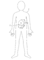
- the illuminating device 1 is used, for example, when operating inside a human chest cavity or abdominal cavity S (shown in FIGS. 5 and 6).
- the lighting device 1 includes a light emitting unit 4, a fixing unit 5 for fixing the light emitting unit 4 to the head of a doctor A (shown in FIG. 4) as a medical worker, two auxiliary lighting units 6 and 6, and light emission And a power supply unit 7 for supplying power to the unit 4 and the auxiliary illumination units 6 and 6, respectively.
- the lighting device 1 can be used by a nurse or the like in addition to the doctor A.
- the light emitting unit 4 includes a plurality of white light emitting diode mounting boards 10, 10... On which white light emitting diodes 2,.
- the red light emitting diode 3 is painted black.
- the case 13 is formed in a rectangular parallelepiped that is long in the left-right direction when attached to the doctor A (shown in FIG. 4).
- the material of the case 13 is, for example, a material with good heat dissipation such as an aluminum alloy.
- a housing space R (shown only in FIG. 3) for housing the substrates 10, 11, 12 is formed in the case 13.
- the accommodation space R is opened in a substantially rectangular shape on the front surface of the case 13.
- a substrate fixing plate 15 to which the mounting substrate 12 is fixed is provided so as to extend in the vertical direction.
- the substrate fixing plate 15 is formed with cooling ventilation holes (not shown) for cooling the light emitting diodes 2 and 3 that generate heat during lighting.
- a cooling fan 18 is disposed on the back side of the substrate fixing plate 15 in the case 13. Further, on the side surface of the case 13, exhaust holes 13a, 13a,... Communicating with the portion where the cooling fan 18 is disposed in the case 13 are opened.
- Each exhaust hole 13a is provided with a filter made of fibers having both water repellency and air permeability such as Gore-Tex (registered trademark). Thereby, it is suppressed that the dust etc. inside case 13 are discharged outside.
- the material of the filter may be a nonwoven fabric, for example.
- the cooling fan 18 is, for example, a silent type provided in a personal computer or the like, and the operating sound is difficult for the doctor A to hear. Air is sent to the light emitting diodes 2 and 3 by the operation of the cooling fan 18. The air heated by cooling the light emitting diodes 2, 3 and the like is exhausted from the exhaust hole 13 a to the side of the case 13. Thereby, the heated air does not directly hit the doctor A or the patient C.
- the material of the case 13 is not limited to an aluminum alloy, and may be composed of a heat-resistant resin material.
- a thermoelectric element such as a Peltier element may be provided to cool the light emitting diodes 2, 3 and the like.
- a stepped portion 13 a is formed at the opening peripheral edge of the housing space R of the case 13.
- the lens 16 is fitted into the stepped portion 13a.
- the lens 16 is formed in a rectangular plate shape that covers the opening of the accommodation space R, and can be made of, for example, a resin material or glass.
- side plate portions 14 projecting from both sides in the longitudinal direction of the case 13 are formed.
- an insertion hole 14 a through which the support shaft 52 of the fixing portion 5 is inserted is formed in the longitudinal direction of the case 13.
- the terminal 20 is provided on the side surface of the case 13. As shown in FIGS. 1 and 4, a power cord 21 extending from the power supply unit 7 is connected to the terminal 20.
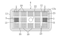
- the mounting substrate 12 has a rectangular shape that is long in the left-right direction.
- the surface of the mounting substrate 12 is coated with a reflective material that reflects light.
- twelve connectors (connection portions) 23, 23,... To which the mounting boards 10, 11 are detachably attached are arranged on the surface of the mounting substrate 12. They are arranged in 4 rows. A predetermined gap is provided between the adjacent connectors 23 and 23.
- the mounting substrate 12 is provided with wiring (not shown) that is electrically connected to terminals (not shown) of the connector 23.
- the wiring of the mounting substrate 12 is electrically connected to the terminal 20 of the case 13.
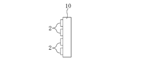
- Each white light emitting diode mounting substrate 10 is, for example, a 10 mm ⁇ 10 mm square. As shown in FIGS. 7 and 8, a total of 16 white light emitting diodes 2, 2,... Are arranged on the surface of the white light emitting diode mounting substrate 10 so that four white light emitting diodes 2, 2,. It has been. A predetermined gap is provided between the adjacent white light emitting diodes 2 and 2. A terminal (not shown) that is electrically connected to the white light emitting diode 2 is provided on the back surface of the white light emitting diode mounting substrate 10. The terminals of the white and red light emitting diode mounting boards 10 and 11 are connected to the terminals of the connector 23 of the mounting board 12. The red light emitting diode substrate 11 is configured in the same manner as the white light emitting diode substrate 10.
- the size and shape of the white and red light emitting diode mounting substrates 10 and 11 are not limited to the above. Further, the number and arrangement of the white and red light emitting diodes 2 and 3 mounted on one substrate 10 and 11 are not limited to the above and can be arbitrarily set.
- the density of the white and red light emitting diodes 2 and 3 is preferably 25 or more per square centimeter in order to obtain sufficient brightness. Further, the intensity of light emitted from each of the white light emitting diode mounting substrates 10, 10,... May be varied.
- the intensity of light emitted from the light emitting unit 4 can be changed depending on the number of light emitting diodes 2 and 3, the number of mounting substrates 10 and 11, the type of light emitting diodes 2 and 3, the supply voltage, and the like. Further, the light irradiation range can be arbitrarily set by the design of the lens 16 and the arrangement position of the light emitting diodes 2 and 3. In this embodiment, as shown in FIG. 9, the illuminance within a substantially ellipse having a major axis of 250 mm and a minor axis of 200 mm is 30000 to 60000 lux at a distance of 600 mm from the front surface of the light emitting unit 4 in a direction perpendicular to the front surface. It is set to become.
- the illuminance of the area surrounded by the broken line at the center of the ellipse is 60000 lux.
- the broken line is a substantially oval shape having a major axis of about 150 mm and a minor axis of about 100 mm.
- the illuminance of the shaded area other than the area surrounded by the broken line is 30000 lux at the minimum.
- the illuminance of the area surrounded by the broken line is preferably 40000 lux or more.
- the substantially elliptical shape having a major axis of 250 mm and a minor axis of 200 mm is a shape corresponding to the shape of the incision T formed when operating on the chest and abdomen of the patient C shown in FIGS. Therefore, by setting the illuminance in the substantially elliptical range to 30000 to 60000 lux, it is possible to deal with most of chest and abdominal surgery.
- the illuminance can be adjusted by removing the white light emitting diode 2 to the red light emitting diode 3 from the connector 23.
- the focal point and irradiation range of light can be changed by the design of the lens 16. Also, it is possible to vary the brightness depending on the part within the irradiation range by the design of the lens 16.
- the color reproducibility and color rendering can be changed by the ratio of the number of white light emitting diodes 2 and the number of red light emitting diodes 3 in the light emitting section 4.
- the color reproducibility and color rendering are suitable for observing the human tissue.
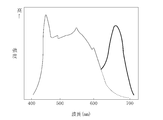
- the intensity of the red region having a wavelength of 600 nm or more is remarkably low, and a human tissue, particularly an incision is obtained.
- the red color of blood or the like is not clear and is not very suitable as surgical light.
- the red light emitting diode 3 is provided (indicated by a thick solid line), the intensity of the red region is increased and human It is possible to obtain color reproducibility and color rendering suitable for observing the tissue.
- the white light emitting diode mounting substrate 10 is removed from the connector 23 and the red light emitting diode substrate 11 is attached to the connector 23 to increase the intensity of the red region. That is, in this embodiment, when changing the color reproducibility and color rendering, it can be easily performed by attaching and detaching the mounting boards 10 and 11, so that the color reproducibility and color rendering depending on the patient C.
- the color reproducibility and color rendering can be changed according to the preference of the doctor A.
- the type of the white light emitting diode 2 may be different in one white light emitting diode mounting substrate 10.
- the white light emitting diode 2 and the red light emitting diode 3 for example, a mounting board on which a light emitting diode that emits infrared light is mounted can be attached to some connectors 23.
- the infrared rays are preferably near infrared rays having a wavelength of 900 to 1100 nm.
- the white balance can be changed by changing the ratio of the number of white light emitting diodes 2 to the number of red light emitting diodes 3.
- the heat insulating material on the rear side of the case 13.
- the heat of the light emitting diodes 2 and 3 is hardly transmitted to the doctor A, and the usability is improved.
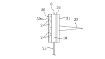
- the auxiliary illumination unit 6 includes a white light emitting diode mounting substrate 10 on which the white light emitting diode 2 is mounted, a front cover 30 and a rear cover 31 that cover each of the front and rear surfaces of the mounting substrate 10, and heat insulation.
- a material 36 and a fixing needle 32 are provided.
- the white light emitting diode mounting substrate 10 is configured in the same manner as described above.
- a lens portion 30 a is provided at a portion facing the light emitting diode 2 in the front cover portion 30.
- a power cord 35 extending to the power supply unit 7 is connected to the wiring of the white light emitting diode mounting substrate 10.
- a terminal connected to the terminal of the power supply unit 7 is provided at the tip of the power cord 35. When the auxiliary illumination unit 6 is not used, the terminal of the power cord 35 can be removed from the terminal of the power source unit 7 and removed.
- the heat insulating material 36 is provided between the white light emitting diode mounting substrate 10 and the rear cover 31, and is for suppressing heat generated by the white light emitting diode 2 from being transmitted to the rear cover 31 and the needle 32.
- the heat insulating material 36 can be composed of various foam materials.
- the heat insulating performance of the heat insulating material 36 is set so that the temperature of the rear cover 31 and the needle 32 does not exceed 38 ° C. even when the white light emitting diode 2 is continuously turned on for 2 to 3 hours. This prevents low temperature burns.
- the needle 32 is provided so as to protrude rearward from the rear cover 31.
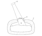
- the auxiliary illumination unit 6 can be fixed at an arbitrary position by inserting the needle 32 into a human tissue.
- the needle 32 is preferably made of a material that hardly affects the living body.
- the needle 32 may be made of stainless steel or titanium alloy.
- the auxiliary illumination unit 6 may be provided with a red light emitting diode or a light emitting diode that emits infrared light.
- the power supply unit 7 includes a battery case 40 that houses a battery.
- the battery case 40 is provided with a switch 41 for turning on the light emitting unit 4 and a switch 42 for turning on the auxiliary lighting unit 6.
- the light emitting unit 4 and the auxiliary lighting unit 6 are individually turned on. It can be done.
- the battery case 40 is provided with a display unit 43 for displaying the remaining battery level, and is also provided with a brightness adjustment switch 44.
- the intensity of light emitted from the light emitting diodes 2 and 3 can be adjusted by operating the brightness adjustment switch 44.
- Reference numeral 8 shown in FIG. 1 indicates a spare battery, and power is supplied from the spare battery 8 when the battery of the power supply unit 7 is exhausted.
- the power supply unit 7 may be provided with an adjustment unit that adjusts the intensity of light emitted from the light emitting unit 4.
- the power supply unit 7 and the spare battery 8 can be fixed to the doctor A's waist using, for example, a belt 100.
- a battery as a power source, there is an advantage that it is difficult for electromagnetic interference to occur in peripheral medical devices.
- the capacities of the power supply unit 7 and the spare battery 8 are set so that the lighting time of the light emitting unit 4 can be about 4 to 5 hours.
- the fixing unit 5 includes a headband 50 that extends so as to surround the periphery of the head, a support band 51 that extends so as to pass through the top of the head, and a support member 53 that supports the light emitting unit 4. ing. Both sides in the longitudinal direction of the headband 50 are formed so as to overlap in the thickness direction at the back of the head. A plurality of holes 50a, 50a,... Are provided on one side in the longitudinal direction of the headband 50 at intervals in the longitudinal direction, while a protrusion 50b that fits into the hole 50a is provided on the other side in the longitudinal direction. It has been.
- the headband 50 has an annular shape by fitting the protrusion 50b into any one of the holes 50a.
- the diameter of the headband 50 at this time can be changed by a hole 50a into which the protrusion 50b is inserted.
- the diameter of the headband 50 may be changeable using other structures.
- the support band 51 is integrated with the headband 50 and is cut at an intermediate portion in the longitudinal direction so as to overlap in the thickness direction.
- a hole 51 a and a protrusion 51 b are provided in the portion of the support band 51 that overlaps in the thickness direction, and the length of the support band 51 can be adjusted.
- the support member 53 is formed to engage with the headband 50.
- the support member 53 is provided with a support shaft 52 extending in the left-right direction of the wearer.
- the support shaft 52 is inserted into the insertion hole 14 a of the side plate portion 14 of the case 13.
- the light emitting unit 4 is supported by the fixing unit 5. Further, the light emitting unit 4 is vertically moved around the support shaft 52 (the direction indicated by the arrows in FIGS. 3 and 4). ) To adjust the angle of the light emitting unit 4, that is, change the light irradiation angle.
- the support shaft 52 and the insertion hole 14a constitute an irradiation angle changing unit of the present invention.
- the light emitting unit 4 is provided with a screw for fixing to the support member 53 when the light emitting unit 4 is at a desired rotation angle, but the light emitting unit 4 does not rotate unexpectedly by omitting the screw. In this way, resistance may be applied.
- the rotation range of the light emitting unit 4 is preferably about 10 ° to 90 °.
- the angle adjustment structure of the light emitting unit 4 is not limited to the above structure, and various structures can be used.
- the diameter of the headband 50 and the length of the support band 51 are adjusted to match the head of the doctor A who is a medical worker, and the light emitting unit 4 is fixed to the head of the doctor A. At this time, the light emitting unit 4 is positioned on the forehead of the doctor A, and the angle of the light emitting unit 4 is adjusted.
- the power supply unit 7 and the spare battery 8 are attached to the doctor A by the belt 100.
- the switch 41 is operated to turn on the light emitting diodes 2 and 3 of the light emitting unit 4 and the doctor A turns his face toward the operative field, the light emitting unit 4 moves in accordance with the movement of the doctor A. The light is irradiated to the operative field.
- the illuminance of the irradiated region is 30000 to 60000 lux, so that the brightness is sufficient to perform surgery even in the absence of a surgical light. Since such a wide range is brightly illuminated, doctor A can recognize the bleeding when sudden bleeding occurs from a place other than the part where the procedure is performed.
- the subcutaneous fat layer and muscle layer may be thick and the thoracic cavity and abdominal cavity may be deep (depth is about 200 mm to 500 mm).
- the illuminance at a distance of 600 mm from the illuminant 4 is 60000.
- the light emission part 4 since the light emission part 4 is being fixed to the doctor A's head at the time of illumination of an operating field, it moves according to the movement of the doctor A, and further, the doctor A moves the head as the doctor A desires. It is possible to change the light irradiation direction. Moreover, since the light emission part 4 moves only by the movement of the doctor A, the possibility that dust or the like falls on the patient C is extremely low.
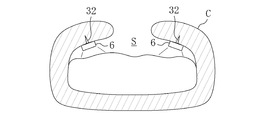
- the auxiliary illumination unit 6 After incising the body surface tissue, the auxiliary illumination unit 6 is placed in the thoracic cavity or the abdominal cavity S as shown in FIG. Specifically, the auxiliary illumination unit 6 is fixed to the patient C by inserting the needle 32 of the auxiliary illumination unit 6 into the tissue near the wound formed by incision from the inside.
- the light emitting diode 2 of the auxiliary illumination unit 6 is turned on by operating the switch 42 of the power supply unit 7, the inside of the chest cavity or the abdominal cavity S is directly illuminated. Thereby, it becomes difficult to make a shadow in the chest cavity and the abdominal cavity S, and the doctor A can see a wide range.
- the brightness adjustment switch 44 is operated to increase the intensity of light emitted from the light emitting diodes 2 and 3, so The illuminance on the side may be 40000 to 60000 lux.
- the illumination device 1 As described above, according to the illumination device 1 according to the first embodiment, it is possible to reliably illuminate from a nearby place without using a large illumination device such as a surgical light during surgery. Therefore, it is not necessary to reinforce the ceiling, etc., and it is possible to reduce the cooling cost and the power consumption. In addition, the operating light is not required to be cleaned and sterilized, and the lighting device 1 is introduced. Cost can be reduced. In addition, since the lamp unit and the movable mechanism are not required, the possibility that dust having bacteria or the like will fall on the patient C is extremely low, and the occurrence of infectious diseases can be suppressed. Moreover, since the light emission part 4 moves according to the movement of the doctor A, the light irradiation direction can be changed as the doctor A desires, and the doctor A can be prevented from feeling stress during the medical practice.
- the illumination device 1 can reliably illuminate a necessary part from a nearby place, it is possible to perform a medical practice in an outpatient treatment room, a cardiac catheter room, an emergency outpatient room, etc. without a surgical light. it can.
- the light emitting unit 4 includes the white light emitting diode 2 and the red light emitting diode 3, when the human tissue is irradiated with light from the light emitting unit 4, the color reproducibility and color rendering can be improved. It can be suitable for observation. Thereby, a blood vessel etc. can be grasped
- the temperature distribution of the tissue can be obtained as an image using an infrared thermography camera. Based on this temperature distribution image, the position and shape of the blood vessel, the amount of blood flowing in the blood vessel, and the like can be grasped and used for medical practice.
- the light emitting diodes 2 and 3 can be attached and detached, the color reproducibility and color rendering can be changed, and the brightness can be changed.
- auxiliary illumination unit 6 disposed in the human chest cavity or the abdominal cavity S is provided, when operating the chest cavity or the abdominal cavity S, the inside of the chest cavity or the abdominal cavity S can be brightened to make it difficult to produce a shadow. , Can improve the safety of medical practice.
- the auxiliary illumination unit 6 since the auxiliary illumination unit 6 is provided with the needle 32, the auxiliary illumination unit 6 can be fixed at an arbitrary position in the chest cavity or the abdominal cavity S, and a desired site can be reliably illuminated.
- the doctor A can take an easy-to-operate posture.
- the light emitting unit 4 may be provided with one of a green light emitting diode and a blue light emitting diode, or both. Even when a green light emitting diode or a blue light emitting diode is provided, a mounting board on which these light emitting diodes are mounted can be connected to the connector 23. By providing the green light emitting diode or the blue light emitting diode, the spectrum of the light emitted from the light emitting unit 4 can be brought close to the spectrum of natural light, and thus the burden on the eyes of the doctor A can be reduced and fatigue can be reduced.
- the auxiliary illumination unit 6 may be provided with a green light emitting diode or a blue light emitting diode.
- auxiliary illumination part 6 may be one, 3 There may be more than one. Further, the auxiliary illumination unit 6 may be omitted.
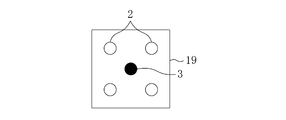
- the white light emitting diode 2 and the red light emitting diode 3 may be mounted on one mounting substrate 19.
- four white light emitting diodes 2 are arranged on the peripheral portion of the mounting substrate 19, and the red light emitting diode 3 is arranged in the central portion of the mounting substrate 19.
- the number of white light emitting diodes 2 and red light emitting diodes 3 can be set arbitrarily.
- the light emitting unit 4 may be provided with a camera 22.
- the camera 22 is an infrared camera.
- a wireless transmitter 24 shown in FIG. 16 for wirelessly transmitting video captured by the camera 22 is provided in the case 13 of the light emitting unit 4.
- the wirelessly transmitted video is displayed on a monitor (not shown) installed in the operating room. Doctor A can check the video on the monitor.
- the auxiliary lighting unit 6 may be provided with the above camera.
- the normal camera 34 is provided in the auxiliary
- the doctor A can confirm the back of the body cavity on the monitor.
- a dye such as indocyanine green (ICG)
- ICG indocyanine green
- the lens 16 By coloring the lens 16 in orange or red, it becomes possible to irradiate light having a wavelength suitable for observing a human tissue or the like without using the red light-emitting diode 3. Etc. becomes easier to see.
- the lens 16 itself may be colored, or a colored film may be attached to the lens 16. Further, by attaching a film to the lens 16, it is also possible to suppress heat radiation.
- (Embodiment 2) 17 and 18 show an illumination device 1 according to Embodiment 2 of the present invention.
- the lighting device 1 according to the second embodiment is the same as that according to the first embodiment in that the camera 54 is provided in the light emitting unit 4 and the light emitting diodes 2 and 3 are provided on both sides of the camera 54 so as to be movable. Since the other parts are the same, the same parts as those of the first embodiment are denoted by the same reference numerals and the description thereof will be omitted, and different parts will be described in detail.
- the light emitting unit 4 includes a main body portion 4a and left and right light emitting diode mounting portions 4b and 4c provided on the left and right sides of the main body portion 4a (left and right sides of the wearer), respectively.
- the camera 54 is provided in the main body 4a. This camera 54 is an infrared camera.
- the main body 4a incorporates a wireless transmitter (not shown) as in the second modification of the first embodiment.
- a hinge mechanism 55 having a pivot shaft extending in the vertical direction is provided on the left side of the main body portion 4a, and the main body portion 4a and the left light emitting diode mounting portion 4b are connected via the hinge mechanism 55. Further, a hinge mechanism 56 similar to that on the left side is provided on the right side of the main body portion 4a, and the main body portion 4a and the right light emitting diode mounting portion 4c are connected via the hinge mechanism 56. Accordingly, as shown in FIG. 18, the left light emitting diode mounting portion 4 b rotates around the rotation axis of the hinge mechanism 55, and the right light emitting diode mounting portion 4 c rotates about the rotation axis of the hinge mechanism 56. .
- the hinge mechanisms 55 and 56 are configured to lock the attachment portions 4b and 4c so that they do not move unexpectedly when the left and right light emitting diode attachment portions 4b and 4c are rotated to an arbitrary position.
- the left light emitting diode mounting portion 4b is formed in a plate shape, and a plurality of the white light emitting diode mounting substrate 10 and the red light emitting diode mounting substrate 11 of the first embodiment are mounted on the front side.
- the right light emitting diode mounting portion 4c is configured in the same manner as the right side.
- the positions of the left light emitting diode mounting portion 4b and the right light emitting diode mounting portion 4c can be individually adjusted. For example, when the positions of the left light emitting diode mounting portion 4b and the right light emitting diode mounting portion 4c are adjusted so as to be close to each other, the light emitted from both the mounting portions 4c and 4b may gather in a narrow range and be locally brightened. Is possible. Further, if the left light emitting diode mounting portion 4b and the right light emitting diode mounting portion 4c are positioned so as to move away from each other, a wide range can be illuminated.
- the hinge mechanisms 55 and 56 constitute an irradiation angle changing unit of the present invention.
- the second embodiment similarly to the first embodiment, it is possible to illuminate a necessary part at a low cost without using a large illumination device such as a surgical light at the time of surgery.
- the light irradiation direction can be changed as desired by the doctor A without dropping dust or the like on the patient.
- the light emitting diodes 2 and 3 can be dispersed in a wide range, the heat generated from the light emitting diodes 2 and 3 becomes difficult to accumulate, and the occurrence of a thermal failure can be suppressed.
- the left light emitting diode mounting portion 71 and the right light emitting diode mounting portion 72 may be connected via one hinge mechanism 70.
- the control board and the like are built in the left light emitting diode mounting portion 4b and the right light emitting diode mounting portion 4c. Thereby, the illuminating device 1 can be made compact. Further, the camera 54 is attached to the hinge mechanism 70.
- the left light emitting diode mounting portions 4b and 71 and the right light emitting diode mounting portions 4c and 72 may be moved using an electric actuator such as a motor.
- a switch for moving the left light emitting diode mounting portions 4 b and 71 and the right light emitting diode mounting portions 4 c and 72 can be provided in the power supply unit 7.
- FIG. 20 shows an illumination device 1 according to Embodiment 3 of the present invention.
- the illuminating device 1 of Embodiment 3 fixes the auxiliary
- the second embodiment is different from the first embodiment, and the other portions are the same. Therefore, the same portions as those of the first embodiment are denoted by the same reference numerals and the description thereof is omitted, and different portions are described in detail. To do.
- the auxiliary illumination unit 6 does not have a needle and is attached to the protective device 60.
- the protector 60 is for protecting the wound part D (shown in FIG. 23) formed by incision of the body surface tissue when operating the chest or abdomen.
- the protector 60 includes a resin-made intermediate sheet 61, a first liquid-absorbing material 62 disposed on the front side of the intermediate sheet 61, and the first liquid-absorbing material 62 with the intermediate sheet 61.
- a pressure sensitive adhesive 68 and a release sheet 69 that covers the pressure sensitive adhesive 68 are provided in a portion away from the base material 64.
- the intermediate sheet 61 is made of a rectangular translucent film made of polyethylene.
- the dimension of the intermediate sheet 61 in the longitudinal direction is about 210 mm, and the dimension in the width direction is about 150 mm. As shown in FIG. 21, the four corners of the intermediate sheet 61 are configured with curves.
- the intermediate sheet 61 may be composed of polyurethane, polyvinyl chloride, or the like, or may be composed of a multilayer film in which these resin materials are laminated.
- the first liquid absorbing material 62 is composed of water-swellable fibers.
- this water-swellable fiber a run seal made by Toyobo Co., Ltd., which is composed of an inner layer of acrylic fiber and an outer layer made of a water-absorbing resin, can be used.
- the water absorption speed of the water-swellable fiber is a speed for absorbing about 50% or more of the equilibrium water absorption amount in about 10 seconds when contacted with water.
- the water-swellable fiber has a property that, after absorbing water, it does not separate even if a certain pressure is applied, and does not dissolve in water.
- the first liquid-absorbing material 62 may be made of gauze made of cotton, rayon, or the like, or a non-woven fabric obtained by mixing the above-mentioned water-swellable fiber with cotton or rayon, or a water-swellable fiber with cotton or rayon. You may comprise by the laminated body laminated
- the first cloth material 63 is made of a non-woven fabric having water permeability.
- the nonwoven fabric which comprises this 1st cloth material 63 has the heat seal property welded to a resin material by applying heat.
- the adhesive 68 is provided on the back side of the intermediate sheet 61.
- the pressure-sensitive adhesive 68 is an acrylic, silicone, polyurethane, or rubber type that is generally used for application to human skin.
- the release sheet 69 is obtained by releasing a resin sheet or paper with a silicone release agent or the like.
- a resin sheet for example, a polyethylene terephthalate film or a polypropylene film can be used.
- the release sheet 69 is made of paper, glassine paper, clay coated paper, laminated paper, etc. Can be used.
- the base material 64 is formed by combining a large number of resin wire materials in a net shape, and has substantially the same shape as the first liquid absorbing material 62 in plan view.
- Each wire is made of a resin material having shape retaining properties that keeps the bent shape without being cut halfway when bent.
- this resin material for example, polyethylene, polypropylene, polyester, nylon or the like can be used. In this embodiment, polyethylene having the best shape retention among these resin materials is used.
- the second liquid absorbing material 66 and the second cloth material 67 are the same as the first liquid absorbing material 62 and the first cloth material 63, respectively.
- the protective device 60 is stored in a bag made of a resin film having no moisture permeability together with sterilization paper. For this reason, it is possible to prevent the first liquid-absorbing material 62 and the second liquid-absorbing material 66 from absorbing moisture in the air during storage and reducing the liquid-absorbing capacity.
- auxiliary illumination parts 6, 6,... are attached to the first cloth material 63 of the protector 60. These auxiliary illumination units 6, 6,... Are electrically connected.
- the number of auxiliary illumination units 6 may be one.
- the protective device 60 is oriented so that the second cloth material 67 is on the wound part D side, and then on the edge of the wound part D. Bend along, and cover the edge of the wound part D with the protective device 60. Thereafter, the release sheet 69 is peeled off from the pressure-sensitive adhesive 68, and the sticking portion 68 is brought into close contact with the skin surface. Thereby, the protective device 60 becomes difficult to shift from the edge of the wound part D. Further, the auxiliary illumination units 6, 6,... Are arranged in the chest cavity or the abdominal cavity S.
- blood that bleeds from the wound portion D during operation and exuded body fluid pass through the second cloth material 67 and are absorbed by the second liquid absorbing material 66.
- symbol 34 shown in FIG. 21 is the same camera provided in the auxiliary
- FIG. The image of the camera 34 is displayed on a monitor by wireless communication or via a signal line. Thereby, it becomes possible to observe a deep part of a body cavity that is difficult to see during surgery, and a bleeding part, a lesion part, and the like can be confirmed.
- the third embodiment similarly to the first embodiment, it is possible to illuminate a necessary part at low cost without using a large illumination device such as a surgical light at the time of surgery.
- the light irradiation direction can be changed as desired by the doctor A without dropping dust or the like on the patient.
- the auxiliary illumination unit 6 is attached to the protective device 60, the tissue of the patient C is not damaged when the auxiliary illumination unit 6 is fixed to the patient C, and can be made minimally invasive.
- the illumination devices 1 of Embodiments 1 to 3 can be used for operations other than those in the thoracic cavity and the abdominal cavity S, and can also be used at the time of diagnosis and examination.
- the shape of the case 13 of the light emitting unit 4 is not limited to the rectangular box shape.
- the case 80 may be circular as viewed from the front as in Modification 1 shown in FIGS.
- a stepped portion 80 a into which the lens 81 is fitted is formed at the opening peripheral portion of the case 80.
- the substrate fixing plate 82 has a concave shape that curves toward the side (rear side) opposite to the lens 81 of the case 80.
- the mounting substrate 83 is curved in a concave shape along the substrate fixing plate 82.
- the surface of the mounting substrate 83 is coated with a reflective material.
- Reference numeral 84 in FIG. 25 denotes a connector.
- symbol 85 in FIG. 26 is a side-plate part, and the code
- symbol 85a is an insertion hole.
- the white light emitting diode mounting substrate 10 and the red light emitting diode mounting substrate 11 are provided so that the light emission direction faces the center of the case 80. Thereby, it becomes possible to brighten the center part of the irradiation range.
- the white light emitting diodes 2, 2,... ... may be provided.
- the light emission direction of the white light emitting diodes 2, 2,... can be easily set to a desired direction.
- Other light emitting diodes can be provided as well.
- the auxiliary lighting unit 6 may be provided with a battery 90. This eliminates the need for the power cord for the auxiliary illumination unit 6.
- the battery 90 may be replaceable or may not be replaceable.
- the battery 90 may be a rechargeable battery.
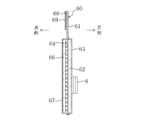
- the support member 53 and the light emitting unit 4 may be separated. That is, the support member 53 is provided with a bar 59 protruding from the front surface of the support member 53. A support shaft 52 is provided on the distal end side of the bar 59, and the support shaft 52 is inserted into the insertion hole 14 a of the light emitting unit 4.
- the movable range of the light emitting unit 4 is not easily limited by the support member 53, and the movable range of the light emitting unit 4 can be expanded. Further, the heat of the light emitting diodes 2 and 3 emitted from the light emitting unit 4 is difficult to be transmitted to the doctor A.
- the operation rod 75 is detachably attached to the light emitting unit 4.
- the operation rod 75 is attached by being screwed into a screw hole (not shown) formed in the light emitting unit 4 or by being fitted into a fitting hole (not shown) formed in the light emitting unit 4.
- the doctor A can easily change the angle of the light emitting unit 4 with the operation rod 75. By removing the operating rod 75 from the light emitting unit 4 after changing the angle, the operating rod 75 does not interfere with the procedure.
- the operation rod 75 is preferably sterilized.
- the attachment portion of the operation rod 75 is preferably on the lower side of the light emitting unit 4, but may be on the upper side.
- the operation rod 75 can also be provided on the left side light emitting diode attaching part 4b and the right side light emitting diode attaching part 4c of the second embodiment.
- auxiliary illumination unit 6 can be packaged and sold separately from the light emitting unit 4 and the fixed unit 5.
- the light emitting unit 4 is provided with an inclination detection sensor for detecting the inclination and a control unit for controlling the light emitting diodes 2 and 3, and the light emitting diodes 2 and 3 are controlled based on the output signal of the inclination detecting sensor. Also good. Specifically, the light-emitting diodes 2 and 3 are turned on when the doctor A is performing a procedure while facing down, while one of the light-emitting diodes 2 and 3 is turned on when the doctor A is facing the front or upward. The light emitting diodes 2 and 3 are turned on darkly. Thereby, it can suppress that the person located in front of the doctor A feels glare, and can also suppress consumption of a battery.
- a shutter device may be provided in front of the light emitting unit 4 and the shutter device may be controlled based on the output signal of the tilt detection sensor. Specifically, when the doctor A is performing a procedure facing down, the shutter device is controlled so as not to cover the light emitting unit 4. On the other hand, when the doctor A faces the front or faces upward, the shutter device covers all or part of the front surface of the light emitting unit 4.
- the light emitting diodes 2 and 3 are provided in the light emitter 4, but the present invention is not limited thereto, and for example, a discharge lamp or the like may be provided.
- the illumination device according to the present invention can be used for, for example, surgery in the thoracic cavity or the abdominal cavity.
Abstract
照明装置1は、発光ダイオードを有する発光部4と、発光部4を医療従事者の頭に固定する固定部5とを備えている。発光部4の光を照射することにより、無影灯が不要になる。発光部4を頭に固定したことで、医療従事者の動きに合わせて発光部4が移動し、さらに、医療従事者が頭を動かすことで望むように光の照射方向を変えることができる。また、補助照明部6やカメラ22を用いることで手術を安全に行うことができる。
Description
本発明は、医療従事者が手術等の医療行為を行う際に使用する照明装置に関する。
一般に、手術室には、術野を照明する照明装置として、術野に影ができないようにする無影灯が設置されている(例えば、特許文献1参照)。この無影灯は、多数のランプを有するランプユニットを備えており、このランプユニットは、通常、手術室の天井に可動機構を介して取り付けられている。そして、実際に手技を行う医師の要求に合うようにランプユニットの位置を調整して使用されている。
ところが、無影灯は多数のランプを可動機構を介して天井に取り付けるように構成されているので全体として大がかりで重い設備となり、天井に補強等が必要になる。
また、ランプユニットの各ランプから熱が発せられるので、室内の温度上昇を抑制するための冷房費用が多くかかる。
また、多数のランプを点灯させるようにしているので、電力消費量が大きなものとなる。
また、手術中に医師が動いてランプユニットが医師の後方に位置した場合には、ランプユニットからの光が医師により遮られてしまい、術野が暗くなるので、ランプユニットの位置を変更しなければならない。この場合、一般には、医師がランプユニットの位置を変更するように助手に指示し、その助手がランプユニットの位置を調整するようにしているので、ランプユニットの位置を調整するための助手が必要になり、人件費の高騰を招く。
さらに、ランプユニットは天井に取り付けられているので、ランプユニットを動かして位置調整する際に、万一、ランプユニットや可動機構から細菌等を有する塵が落下した場合には、それが真下の患者に付着し、患者が感染症を発症する虞れがある。これを抑止するためには、ランプユニット及び可動機構の清掃や殺菌作業が必要で、維持管理に手間がかかる。
上述したように、無影灯を導入するにあたっては多大なコストがかかるという問題がある。
加えて、助手がランプユニットの位置を調整するときには、変更を指示している者と調整を行う者とが異なっているので、ランプユニットの位置が医師の望み通りになり難く、医師がストレスを感じることがある。
本発明は斯かる点に鑑みてなされたものであり、その目的とするところは、医療従事者が医療行為中に使用する照明装置を低コストで導入できるようにし、しかも、光の照射方向を、塵等の落下を伴うことなく、医療従事者の望み通りに変更できるようにすることにある。
上記目的を達成するために、第1の発明では、発光部と、該発光部を医療従事者の頭に固定するための固定部とを備えている構成とする。
この構成によれば、医療行為時において医療従事者の頭に発光部を固定することにより、無影灯のような多数のランプユニットを有する大がかりな照明装置を用いることなく、近い所から確実に照明することが可能になる。よって、天井に補強等を行わずに済むとともに、冷房費用の低減及び電力消費量の低減も図られる。また、ランプユニットや可動機構が不要になることから、それらの清掃や殺菌作業も不要になる。
照明時には、発光部が医療従事者の頭に固定されていることから、医療従事者の動きに合わせて移動し、さらに、医療従事者が頭を動かすことで本人の望むように光の照射方向を変えることが可能になる。また、医療従事者の動きだけで発光部が動くので、塵等が患者に落下する可能性は極めて低い。
第2の発明では、第1の発明において、発光部は、白色発光ダイオードと赤色発光ダイオードとを有している構成とする。
すなわち、白色発光ダイオードの光を人の組織に照射した場合には、色の見え方は白が強調されて見えることになるので、例えば手術時の血管等を正確に把握し難いことがあるが、発光部が赤色発光ダイオードを有していることにより、白が強調されてしまうのを回避して、色の再現性や演色性を人の組織を観察するのに適したものとすることが可能になる。また、発光部から発する光のスペクトルの赤色領域が強くなるので、例えば手術器具等から反射する光のぎらつきが弱められることになる。
第3の発明では、第1または2の発明において、発光部は、緑色発光ダイオードと青色発光ダイオードとの少なくとも一方を有している構成とする。
この構成によれば、発光部が発する光のスペクトルを自然光のスペクトルに近づけることが可能になる。
第4の発明では、第1から3のいずれか1つの発明において、発光部は、赤外線を放射する発光ダイオードを有している構成とする。
この構成によれば、赤外線が人の組織に照射されることになるので、例えば、赤外線サーモグラフィカメラを用いて人の組織を撮影した場合に、組織の温度分布を画像として得ることが可能になる。
第5の発明では、第2または3の発明において、発光部は、発光ダイオードが着脱される接続部を有している構成とする。
この構成によれば、特定の色の発光ダイオードを接続部から外して他の色の発光ダイオードを装着することによって色の再現性や演色性を変えることが可能になる。また、発光ダイオードの数を減らして明るさを変えることも可能になる。
第6の発明では、第1から5のいずれか1つの発明において、人の胸腔または腹腔内に配置される補助照明部を備えている構成とする。
この構成によれば、例えば胸腔や腹腔を手術する際に、胸腔や腹腔内を直接照明することが可能になる。
第7の発明では、第6の発明において、人の体表側組織が切開されて形成された創傷部を保護する保護具に補助照明部が取り付けられている構成とする。
この構成によれば、創傷部の保護具に補助照明部を取り付けることで、人の組織に傷等を付けることなく補助照明部を固定することが可能になる。
第8の発明では、第6の発明において、補助照明部には、人の組織に刺すための針が設けられている構成とする。
この構成によれば、補助照明部の針を胸腔や腹腔内の組織に刺すことで、補助照明部を任意の位置に固定することが可能になる。
第9の発明では、第1の発明において、光の照射角度を変更する照射角度変更部を備えている構成とする。
この構成によれば、発光部から照射される光の照射角度を、手技や術者に応じて変更することが可能になる。
第1の発明によれば、発光部を医療従事者の頭に固定するようにしたので、無影灯を用いることなく、必要な部位を確実に照明することができ、照明装置を低コストで導入できる。また、無影灯が不要になることで、細菌を有する塵等が患者に落下することはなく、患者に感染症が発症するのを抑止できる。さらに、医療従事者の動きによって発光部を動かすことができるので、光の照射方向を医療従事者の望み通りに変更でき、医療従事者が医療行為中にストレスを感じないようにすることができる。
また、本発明の照明装置によれば、必要な部位を近いところから確実に照明することができるので、無影灯の無い、外来処置室や、心臓カテーテル室、救急外来室等で医療行為を行うこともできる。
第2の発明によれば、発光部が白色発光ダイオードと赤色発光ダイオードとを有しているので、発光部の光を人の組織に照射した際、色の再現性や演色性を、人の組織を観察するのに適したものとすることができる。これにより、血管等を正確に把握することができ、医療行為の安全性を向上させることができる。また、発光部が赤色発光ダイオードを有していることにより、例えば手術器具等から反射する光のぎらつきを弱めて医療従事者の目にかかる負担を減らして疲労を低減することができる。
第3の発明によれば、発光部が緑色発光ダイオードと青色発光ダイオードとの少なくとも一方を有しているので、発光部が発する光を自然光に近づけることができ、医療従事者の目にかかる負担を減らして疲労を低減することができる。
第4の発明によれば、赤外光を放射する発光ダイオードを備えているので、赤外線サーモグラフィカメラを用いて組織の温度分布を画像として得ることができる。この温度分布画像に基づいて、血管の位置や形状、血管内を流れる血液の量等を把握して、医療行為に役立てることができる。
第5の発明によれば、発光ダイオードを着脱できるので、色の再現性や演色性を変えたり、明るさを変えることが容易に行えるようになる。
第6の発明によれば、人の胸腔または腹腔内に配置される補助照明部を備えているので、胸腔や腹腔を手術する場合に、胸腔や腹腔内を明るくして影が生じ難くすることができ、医療行為の安全性を向上させることができる。
第7の発明によれば、創傷部を保護する保護具に補助照明部を取り付けるようにしたので、補助照明部を人に対し低侵襲に固定できる。
第8の発明では、補助照明部に針を設けたので、補助照明部を胸腔や腹腔内の任意の位置に固定することができ、所望部位を確実に照明することができる。
第9の発明では、光の照射角度を変更することができるので、医療従事者が医療行為を行い易い姿勢をとることができる。
以下、本発明の実施形態を図面に基づいて詳細に説明する。尚、以下の好ましい実施形態の説明は、本質的に例示に過ぎず、本発明、その適用物或いはその用途を制限することを意図するものではない。
(実施形態1)
図1は、本発明の実施形態1に係る照明装置1を示すものである。照明装置1は、例えば、人の胸腔や腹腔S(図5及び図6に示す)内を手術する際に使用されるものである。照明装置1は、発光部4と、発光部4を医療従事者としての医師A(図4に示す)の頭に固定するための固定部5と、2つの補助照明部6、6と、発光部4及び補助照明部6、6にそれぞれ電力を供給する電源部7とを備えている。尚、照明装置1は、医師A以外にも、看護師等が使用することも可能である。
図1は、本発明の実施形態1に係る照明装置1を示すものである。照明装置1は、例えば、人の胸腔や腹腔S(図5及び図6に示す)内を手術する際に使用されるものである。照明装置1は、発光部4と、発光部4を医療従事者としての医師A(図4に示す)の頭に固定するための固定部5と、2つの補助照明部6、6と、発光部4及び補助照明部6、6にそれぞれ電力を供給する電源部7とを備えている。尚、照明装置1は、医師A以外にも、看護師等が使用することも可能である。
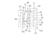
図2及び図3に示すように、発光部4は、白色発光ダイオード2、2、…が実装された複数の白色発光ダイオード実装基板10、10、…と、赤色発光ダイオード3、3、…が実装された複数の赤色発光ダイオード実装基板11、11、…と、これら実装基板10、11が着脱自在に取り付けられる取付基板12と、これら基板10、11、12が収容されるケース13とを備えている。図2において、黒く塗りつぶしたものが赤色発光ダイオード3である。
ケース13は、医師Aに装着された状態(図4に示す)で左右方向に長い直方体に形成されている。ケース13の材料は、例えば、アルミニウム合金等の放熱性の良好な材料である。ケース13内には上記基板10、11、12を収容する収容空間R(図3にのみ示す)が形成されている。この収容空間Rは、ケース13の前面に略矩形状に開口している。収容空間Rの内部には、取付基板12が固定される基板固定板15が上下方向に延びるように設けられている。基板固定板15には、点灯時に発熱する発光ダイオード2、3を冷却するための冷却用の通風孔(図示せず)が形成されている。
ケース13内における基板固定板15の裏側には、冷却ファン18が配設されている。また、ケース13の側面には、ケース13内における冷却ファン18の配設部位に連通する排気孔13a、13a、…が開口している。各排気孔13aには、例えばゴアテックス(登録商標)等の撥水性及び通気性を兼ね備えた繊維からなるフィルタが設けられている。これにより、ケース13内部の塵等が外部に排出されるのが抑制される。フィルタの素材は、例えば不織布等であってもよい。
冷却ファン18は、例えば、パーソナルコンピュータ等に設けられる静音タイプのものであり、作動音が医師Aに聞こえ難くなっている。冷却ファン18の作動により、発光ダイオード2,3等に空気が送られる。発光ダイオード2,3等を冷却して昇温した空気は排気孔13aからケース13の側方へ排気される。これにより、昇温した空気が医師Aや患者Cに直接当たることはない。
尚、ケース13の材料は、アルミニウム合金に限られるものではなく、耐熱性を有する樹脂材で構成することもできる。また、冷却ファン18の代わりに、ペルチェ素子等の熱電素子(図示せず)を設けて発光ダイオード2、3等を冷却するようにしてもよい。
図3に示すように、ケース13の収容空間Rの開口周縁部には、段差部13aが形成されている。この段差部13aには、レンズ16が嵌るようになっている。レンズ16は、収容空間Rの開口を覆う矩形板状に形成されており、例えば樹脂材やガラス等で構成することができる。また、ケース13のレンズ16と反対側の面(後面)には、ケース13の長手方向両側からそれぞれ突出する側板部14が形成されている。側板部14には、固定部5が有する支軸52が挿通する挿通孔14aがケース13の長手方向に貫通形成されている。
ケース13の側面には、端子20が設けられている。この端子20には、図1や図4に示すように、電源部7から延びる電源コード21が接続されるようになっている。
取付基板12は、左右方向に長い矩形状をなしている。取付基板12の表面は、光を反射する反射材によりコーティングされている。取付基板12の表面には、図2に示すように、実装基板10、11が着脱可能に取り付けられる12個のコネクタ(接続部)23、23、…が縦に3つ並び、それが横に4列並ぶように設けられている。隣り合うコネクタ23、23の間には、所定の隙間が設けられている。また、取付基板12には、コネクタ23の端子(図示せず)に電気的に接続される配線(図示せず)が設けられている。この取付基板12の配線は、ケース13の端子20に電気的に接続されている。
各白色発光ダイオード実装基板10は、例えば、10mm×10mmの正方形とされている。図7及び図8に示すように、白色発光ダイオード実装基板10の表面には、白色発光ダイオード2、2、…が縦に4個並び、それが横に4列並ぶように、合計16個設けられている。隣り合う白色発光ダイオード2、2の間には、所定の隙間が設けられている。白色発光ダイオード実装基板10の裏面には、白色発光ダイオード2に電気的に接続される端子(図示せず)が設けられている。白色及び赤色発光ダイオード実装基板10、11の端子は、取付基板12のコネクタ23の端子に接続されるようになっている。赤色発光ダイオード基板11は、白色発光ダイオード基板10と同様に構成されている。
尚、白色及び赤色発光ダイオード実装基板10、11の大きさや形状は上記に限られるものではない。また、1つの基板10、11に実装する白色及び赤色発光ダイオード2、3の数や配置も上記に限られるものではなく、任意に設定できる。白色及び赤色発光ダイオード2、3の密度は、十分な明るさを得るために、1平方センチメートル当たり25個以上が好ましい。また、白色発光ダイオード実装基板10、10、…の各々から照射される光の強さは異ならせてもよい。
上記発光部4から発する光の強さは、発光ダイオード2、3の数、実装基板10、11の数、発光ダイオード2、3の種類、供給電圧等によって変更することが可能である。また、光の照射範囲はレンズ16の設計及び発光ダイオード2、3の配設位置により任意に設定することが可能となっている。この実施形態では、図9に示すように、発光部4の前面から該前面に直交する方向に600mm離れたところで、長径250mm、短径200mmの略楕円内の照度が30000~60000ルクス(lux)となるように設定されている。具体的には、同図に示すように、上記楕円の中央部である破線で囲まれた領域の照度が60000ルクスとされている。破線は、長径約150mm、短径約100mmの略楕円形である。破線で囲まれた領域以外の斜線が引かれた領域の照度は、最低で30000ルクスとされている。尚、破線で囲まれた領域の照度は、40000ルクス以上が好ましい。
長径250mm、短径200mmの略楕円形というのは、図5及び図6に示す患者Cの胸部や腹部を手術する際に形成される切開部Tの形状に対応した形状である。よって、上記略楕円形の範囲の照度を30000~60000ルクスとすることで、胸部及び腹部の手術の大部分に対応できる。
また、照度を上記のように設定することで、手術時に無影灯が無くても、術野の広い範囲を十分な明るさで照らすことが可能となり、手技に支障をきたすことはない。尚、明るすぎる場合には、白色発光ダイオード2乃至赤色発光ダイオード3をコネクタ23から外すことにより、照度を調整することが可能である。光の焦点及び照射範囲は、レンズ16の設計で変更できる。また、照射範囲内において部位によって明るさを異ならせることもレンズ16の設計により可能である。
また、発光部4の白色発光ダイオード2の数と赤色発光ダイオード3の数との比率により、色の再現性や演色性を変更することが可能である。この実施形態では、発光部4の光を人の組織に照射した際、色の再現性や演色性を、人の組織を観察するのに適したものとなるようにしている。図10の発光スペクトルに示すように、発光部4が白色発光ダイオード2のみである場合(破線で示す)には、波長が600nm以上の赤色領域の強度が著しく低く、人の組織、特に切開した組織を観察するに際して血液等の赤色がはっきりとしにくく手術用の光としてあまり適していないが、赤色発光ダイオード3を設けた場合(太い実線で示す)には、赤色領域の強度が強くなり、人の組織を観察するのに適した色の再現性や演色性を得ることができる。光の赤色領域の強さを変更する場合には、白色発光ダイオード実装基板10をコネクタ23から外し、そのコネクタ23に赤色発光ダイオード基板11を取り付けることにより赤色領域の強さが強くなる。つまり、この実施形態では、色の再現性や演色性を変える際には、実装基板10、11の着脱により容易に行えるようになっているので、患者Cに応じて色の再現性や演色性を変えたり、医師Aの好みに応じて色の再現性や演色性を変えることが可能である。
また、1つの白色発光ダイオード実装基板10内で、白色発光ダイオード2の種類を異ならせてもよい。
また、図示しないが、白色発光ダイオード2や赤色発光ダイオード3の代わりに、例えば、赤外線を放射する発光ダイオードが実装された実装基板を一部のコネクタ23に取り付けることもできる。この場合の赤外線は波長が900~1100nmの近赤外線が好ましい。また、白色発光ダイオード2の数と赤色発光ダイオード3の数との比率を変えることにより、ホワイトバランスも変えることができる。
また、ケース13の後側には断熱材を設けるのが好ましい。断熱材を設けることで発光ダイオード2、3の熱が医師Aに伝わりにくくなり、使用感が向上する。
図11に示すように、補助照明部6は、白色発光ダイオード2が実装された白色発光ダイオード実装基板10と、実装基板10の前面及び後面の各々を覆う前面カバー30及び後面カバー31と、断熱材36と、固定用の針32とを備えている。白色発光ダイオード実装基板10は、上記したものと同様に構成されている。前面カバー部30における発光ダイオード2に対向する部分には、レンズ部30aが設けられている。白色発光ダイオード実装基板10の配線には、電源部7まで延びる電源コード35が接続されている。電源コード35の先端部には、図示しないが電源部7の端子に接続される端子が設けられている。補助照明部6を使用しない場合には、電源コード35の端子を電源部7の端子から抜いて外しておくことが可能である。
断熱材36は、白色発光ダイオード実装基板10と後面カバー31との間に設けられており、白色発光ダイオード2が発する熱が後面カバー31や針32に伝わるのを抑制するためのものである。断熱材36は各種発泡材等で構成することができる。断熱材36の断熱性能は、白色発光ダイオード2を2~3時間連続して点灯させても、後面カバー31及び針32の温度が38℃を越えないように設定されている。これにより、低温やけどが防止されるようになっている。
針32は、後面カバー31から後方へ突出するように設けられている。この針32を人の組織に刺すことで、補助照明部6を任意の位置に固定しておくことができるようになっている。針32は、生体に悪影響を殆ど与えない材料で構成するのが好ましく、例えば、ステンレス鋼やチタン合金等で構成するのがよい。尚、補助照明部6に赤色発光ダイオードや赤外線を放射する発光ダイオードを設けてもよい。
図1に示すように、電源部7は、電池を収容する電池ケース40を備えている。電池ケース40には、発光部4を点灯させるためのスイッチ41と、補助照明部6を点灯させるためのスイッチ42とが設けられており、発光部4と、補助照明部6とを個別に点灯できるようになっている。また、電池ケース40には、電池残量を表示する表示部43も設けられるとともに、明るさ調整スイッチ44も設けられている。明るさ調整スイッチ44を操作することで、発光ダイオード2、3から発する光の強さを調整することができるようになっている。図1に示す符号8は、予備電池を示しており、電源部7の電池が消耗した場合に予備電池8から電力が供給されるようになっている。尚、電源部7には、発光部4から発する光の強さを調整する調整部を設けてもよい。
電源部7及び予備電池8は、図4に示すように、例えば、ベルト100を用いて医師Aの腰に固定することが可能である。尚、電源部7には、充電可能な電池を収容するようにしてもよく、この場合は、LiH電池が好ましい。また、予備電池8は複数用意しておくのが好ましい。また、電源を電池とすることで、周辺医療機器に対し電磁波障害が発生し難いというメリットもある。
電源部7及び予備電池8の容量は、発光部4の点灯時間を4時間~5時間程度にすることができるように設定されている。
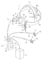
図1に示すように、固定部5は、頭の周囲を囲むように延びるヘッドバンド50と、頭の頂部を通るように延びるサポートバンド51と、発光部4を支持する支持部材53とを備えている。ヘッドバンド50の長手方向両側は、後頭部において厚み方向に重なるように形成されている。ヘッドバンド50の長手方向一側には、複数の孔部50a、50a、…が長手方向に間隔をあけて設けられ、一方、長手方向他側には、孔部50aに嵌入する突起50bが設けられている。突起50bをいずれかの孔部50aに嵌入することでヘッドバンド50が環状をなすようになっている。このときのヘッドバンド50の径は突起50bを嵌入する孔部50aにより変更可能となっている。尚、ヘッドバンド50の径は、他の構造を用いて変更可能にしてもよい。
サポートバンド51は、ヘッドバンド50に一体化されており、長手方向の中間部において切断されて厚み方向に重なるようになっている。このサポートバンド51の厚み方向に重なる部分には、上記ヘッドバンド50と同様に孔部51a及び突起51bが設けられており、サポートバンド51の長さ調整が可能となっている。
図3に示すように、支持部材53は、ヘッドバンド50に係合するように形成されている。支持部材53には、装着者の左右方向に延びる支軸52が設けられている。この支軸52は、上記ケース13の側板部14の挿通孔14aに挿通するようになっている。支軸52が挿通孔14aに挿通された状態で、発光部4が固定部5に支持され、さらに、発光部4は、支軸52周りに上下方向(図3及び図4に矢印で示す方向)に回動して発光部4の角度調節、すなわち、光の照射角度を変更することが可能となっている。支軸52及び挿通孔14aは、本発明の照射角度変更部を構成している。
図示しないが、発光部4には、所望の回動角度にあるときに支持部材53に対し固定するためのネジが設けられているが、ネジを省略して発光部4が不意に回動しないように抵抗を付与するようにしてもよい。発光部4の回動範囲は、10゜~90゜くらいが好ましい。尚、発光部4の角度調節構造としては、上記の構造に限られるものではなく、様々な構造を用いることができる。
次に、上記のように構成された照明装置1を使用する場合について説明する。図4の符号Bは、手術台を示している。
まず、ヘッドバンド50の径及びサポートバンド51の長さを医療従事者である医師Aの頭に合うように調節して、発光部4を医師Aの頭部に固定する。このとき、発光部4を医師Aの額に位置付け、さらに、発光部4の角度を調節する。また、電源部7及び予備電池8はベルト100により医師Aに装着しておく。スイッチ41を操作して発光部4の発光ダイオード2、3を点灯させて、医師Aが術野の方に顔を向けると、発光部4が医師Aの動きに合わせて動き、発光部4からの光が術野に照射される。このとき、発光部4の前面から600mm離れていても、照射部位の照度が30000~60000ルクスになるので、無影灯が無い状況でも手術を行うのに十分な明るさとなる。そのように広い範囲が明るく照らされるので、手技を行っている部分以外のところから急な出血が起こった場合に医師Aはその出血を認識することができるようになる。
また、患者Cの体格によっては、皮下脂肪層や筋肉層が厚く、胸腔や腹腔が深くなる(深さが200mm~500mm程度)ことがあるが、発光体4から600mm離れたところの照度を60000ルクス確保していることで、胸腔や腹腔Sの深いところを30000ルクス以上の照度で照らすことが可能であり、手技に支障をきたすことはない。
また、術野の照明時には、発光部4が、医師Aの頭に固定されていることから、医師Aの動きに合わせて移動し、さらに、医師Aが頭を動かすことで医師Aの望むように光の照射方向を変えることが可能になる。また、医師Aの動きだけで発光部4が動くので、塵等が患者Cに落下する可能性は極めて低い。
体表側組織を切開した後には、図12に示すように、補助照明部6を胸腔内や腹腔S内に配置する。具体的には、補助照明部6の針32を、切開により形成された創傷部近傍の組織に内側から刺すことにより、補助照明部6を患者Cに固定する。そして、電源部7のスイッチ42を操作して補助照明部6の発光ダイオード2を点灯させると、胸腔や腹腔S内が直接照明される。これにより、胸腔や腹腔S内に影ができにくくなり、医師Aは広い範囲を見ることが可能になる。
また、患者Cが例えば肥満体型で、胸腔や腹腔Sが深い場合には、明るさ調整スイッチ44を操作して発光ダイオード2、3から発する光の強さを強くし、胸腔や腹腔Sの奥側における照度が40000~60000ルクスとなるようにすればよい。
以上説明したように、この実施形態1に係る照明装置1によれば、手術時において無影灯のような大がかりな照明装置を用いることなく、近い所から確実に照明することができる。よって、天井に補強等を行わずに済むとともに、冷房費用の低減及び電力消費量の低減を図ることができ、しかも、無影灯の清掃や殺菌作業も不要になり、照明装置1を導入するコストを低減することができる。また、ランプユニットや可動機構が不要になることから、細菌を有する塵等が患者Cに落下する可能性は極めて低く、感染症が発症するのを抑止できる。また、発光部4が医師Aの動きに合わせて移動するので、光の照射方向を医師Aの望み通りに変更でき、医師Aが医療行為中にストレスを感じないようにすることができる。
また、照明装置1においては、必要な部位を近いところから確実に照明することができるので、無影灯の無い、外来処置室や、心臓カテーテル室、救急外来室等で医療行為を行うこともできる。
また、発光部4が白色発光ダイオード2と赤色発光ダイオード3とを有しているので、発光部4の光を人の組織に照射した際、色の再現性や演色性を、人の組織を観察するのに適したものとすることができる。これにより、血管等を正確に把握することができ、医療行為の安全性を向上することができる。また、赤色発光ダイオード3を有しているので、例えば手術器具等から反射する光のぎらつきを弱めて医師Aの目にかかる負担を減らして疲労を低減することができる。
また、赤外線を放射する発光ダイオードを設けた場合には、赤外線サーモグラフィカメラを用いて組織の温度分布を画像として得ることができる。この温度分布画像に基づいて、血管の位置や形状、血管内を流れる血液の量等を把握して、医療行為に役立てることができる。
また、発光ダイオード2、3を着脱できるので、色の再現性や演色性を変えたり、明るさを変えることができる。
また、人の胸腔または腹腔S内に配置される補助照明部6を備えているので、胸腔や腹腔Sを手術する場合に、胸腔や腹腔S内を明るくして影が生じ難くすることができ、医療行為の安全性を向上させることができる。
また、補助照明部6に針32を設けたので、補助照明部6を胸腔や腹腔S内の任意の位置に固定することができ、所望部位を確実に照明することができる。
また、発光部4の角度を調節することができるので、医師Aは手術し易い姿勢をとることができる。
尚、発光部4には、白色発光ダイオード2や赤色発光ダイオード3以外にも、緑色発光ダイオードと青色発光ダイオードとの一方を設けてもよいし、両方を設けてもよい。緑色発光ダイオードや青色発光ダイオードを設ける場合にも、これら発光ダイオードが実装された実装基板をコネクタ23に接続することが可能である。緑色発光ダイオードや青色発光ダイオードを設けることにより、発光部4が発する光のスペクトルを自然光のスペクトルに近づけることができ、よって、医師Aの目にかかる負担を減らして疲労を低減することができる。補助照明部6に緑色発光ダイオードや青色発光ダイオードを設けてもよい。
また、上記実施形態では、照明装置1が2つの補助照明部6、6を備えている場合について説明したが、これに限らず、補助照明部6は、1つであってもよいし、3つ以上であってもよい。また、補助照明部6を省略してもよい。
また、図13に示す変形例1のように、1つの実装基板19に白色発光ダイオード2及び赤色発光ダイオード3を実装するようにしてもよい。この変形例1では、白色発光ダイオード2を実装基板19の周縁部に4つ配置し、赤色発光ダイオード3を実装基板19の中央部に配置している。白色発光ダイオード2及び赤色発光ダイオード3の数は任意に設定できる。
また、図14~図16に示す変形例2のように、発光部4にカメラ22を設けてもよい。カメラ22は、赤外線カメラである。また、発光部4のケース13内には、カメラ22で撮影した映像を無線で送信するための無線送信機24(図16に示す)が設けられている。無線送信された映像は、手術室に設置されているモニター(図示せず)に映し出されるようになっている。医師Aはモニターの映像を確認することが可能となっている。
また、補助照明部6に上記カメラを設けてもよい。これにより、胸腔及び腹腔Sの内部の見えにくいところをモニターで確認することができる。また、この変形例2では、補助照明部6に通常のカメラ34が設けられており、このカメラ34で撮影された映像は、図示しない無線送信機によってモニターに送信されるようになっている。これにより、医師Aは、体腔の奥の方をモニターで確認することができる。尚、カメラ22、34の映像は信号線でモニターに送るようにしてもよい。
また、手術中に、色素、例えばインドシアニングリーン(ICG)を患者Cの血中に投与し、赤外線発光ダイオードで赤外線を照射することで、血流の状態を確認して手術を進行することも可能になる。
また、レンズ16を着色することも可能である。レンズ16をオレンジ色や赤色に着色することで、赤色発光ダイオード3を用いることなく、人の組織等を観察するのに適した波長の光を照射することが可能になり、血管や組織、血液等が見えやすくなる。この場合、レンズ16自体を着色するようにしてもよいし、レンズ16に着色フィルムを貼り付けるようにしてもよい。また、レンズ16にフィルムを貼り付けることで、熱の放射を抑制することも可能になる。
(実施形態2)
図17及び図18は、本発明の実施形態2に係る照明装置1を示すものである。実施形態2の照明装置1は、発光部4にカメラ54を設けた点と、発光ダイオード2、3をカメラ54の両側に設けて動かすことができるように構成した点とで実施形態1のものと異なっており、他の部分は同じであるため、以下、実施形態1と同じ部分には同じ符号を付して説明を省略し、異なる部分について詳細に説明する。
図17及び図18は、本発明の実施形態2に係る照明装置1を示すものである。実施形態2の照明装置1は、発光部4にカメラ54を設けた点と、発光ダイオード2、3をカメラ54の両側に設けて動かすことができるように構成した点とで実施形態1のものと異なっており、他の部分は同じであるため、以下、実施形態1と同じ部分には同じ符号を付して説明を省略し、異なる部分について詳細に説明する。
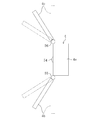
発光部4は、本体部4aと、本体部4aの左右両側(装着者の左右両側)にそれぞれ設けられた左側及び右側発光ダイオード取付部4b、4cとを備えている。カメラ54は、本体部4aに設けられている。このカメラ54は、赤外線カメラである。本体部4aには、上記実施形態1の変形例2のような無線送信機(図示せず)が内蔵されている。
本体部4aの左側には、上下方向に延びる回動軸を有するヒンジ機構55が設けられており、本体部4aと左側発光ダイオード取付部4bとはヒンジ機構55を介して連結されている。また、本体部4aの右側には、左側と同様なヒンジ機構56が設けられており、本体部4aと右側発光ダイオード取付部4cとはヒンジ機構56を介して連結されている。従って、図18に示すように、左側発光ダイオード取付部4bはヒンジ機構55の回動軸周りに回動し、また、右側発光ダイオード取付部4cはヒンジ機構56の回動軸周りに回動する。ヒンジ機構55、56は、左側及び右側発光ダイオード取付部4b、4cを回動させて任意の位置とした際に取付部4b、4cが不意に動かないようにロックするようになっている。
左側発光ダイオード取付部4bは、板状に形成されており、その表側には、実施形態1の白色発光ダイオード実装基板10及び赤色発光ダイオード実装基板11が複数取り付けられている。右側発光ダイオード取付部4cも右側と同様に構成されている。
実施形態2では、左側発光ダイオード取付部4b及び右側発光ダイオード取付部4cの位置を個別に調整することができる。例えば、左側発光ダイオード取付部4b及び右側発光ダイオード取付部4cを、互いに接近するように位置調整すると、両取付部4c、4bから照射された光が狭い範囲に集まり、局部的に明るくすることが可能である。また、左側発光ダイオード取付部4b及び右側発光ダイオード取付部4cを、互いに遠ざかるように位置調整すると広い範囲を照らすことが可能である。つまり、左側発光ダイオード取付部4b及び右側発光ダイオード取付部4cを動かすことで、患者Cの体腔の深さ等に応じて明るさを調整することが可能である。ヒンジ機構55、56は本発明の照射角度変更部を構成している。
したがって、この実施形態2によれば、実施形態1と同様に、手術時において無影灯のような大がかりな照明装置を用いることなく、低コストで必要な部位を照明することができ、また、塵等を患者に落下させることなく、光の照射方向を医師Aの望み通りに変更できる。
また、この実施形態2では、発光ダイオード2、3を広い範囲に分散させることができるので、発光ダイオード2、3から発した熱がこもり難くなり、熱障害の発生を抑制できる。
また、左側発光ダイオード取付部4b及び右側発光ダイオード取付部4cが互いに離れているので、放熱性が高まる。
尚、本体部4aに発光ダイオード2、3を設けてもよい。また、左側及び右側発光ダイオード取付部4b、4cにカメラ54を設けてもよい。
また、図19に示す変形例のように、1つのヒンジ機構70を介して左側発光ダイオード取付部71及び右側発光ダイオード取付部72を連結するようにしてもよい。制御用の基板等は左側発光ダイオード取付部4b及び右側発光ダイオード取付部4cに内蔵されている。これにより、照明装置1をコンパクトにすることができる。また、ヒンジ機構70には、上記カメラ54が取り付けられている。
また、左側発光ダイオード取付部4b、71及び右側発光ダイオード取付部4c、72をモーター等の電動アクチュエータを利用して動かすようにしてもよい。この場合、左側発光ダイオード取付部4b、71及び右側発光ダイオード取付部4c、72を動かすためのスイッチは、電源部7に設けることができる。
(実施形態3)
図20は、本発明の実施形態3に係る照明装置1を示すものである。実施形態3の照明装置1は、補助照明部6を、患者Cの創傷部を保護する保護具60(図21参照)を用いて患者C(図23及び図24に示す)に固定するようにした点で、実施形態1のものと異なっており、他の部分は同じであるため、以下、実施形態1と同じ部分には同じ符号を付して説明を省略し、異なる部分について詳細に説明する。
図20は、本発明の実施形態3に係る照明装置1を示すものである。実施形態3の照明装置1は、補助照明部6を、患者Cの創傷部を保護する保護具60(図21参照)を用いて患者C(図23及び図24に示す)に固定するようにした点で、実施形態1のものと異なっており、他の部分は同じであるため、以下、実施形態1と同じ部分には同じ符号を付して説明を省略し、異なる部分について詳細に説明する。
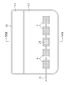
すなわち、補助照明部6は、針を有しておらず、保護具60に貼り付けられるようになっている。保護具60は、胸部や腹部を手術する際に、体表側組織が切開されて形成された創傷部D(図23に示す)を保護するためのものである。保護具60は、図22に示すように、樹脂製の中間シート61と、この中間シート61の表側に配置される第1吸液材62と、第1吸液材62を中間シート61との間で保持する第1布材63と、上記中間シート61の裏側に配置される基材64と、第2吸液材66と、該第2吸液材66を保持する第2布材67とを備えている。また、上記中間シート61の表側には、上記基材64から離れた部位に粘着剤68と、該粘着剤68を覆う剥離シート69とが設けられている。
上記中間シート61は、ポリエチレンからなる矩形の半透明フィルムで構成されている。中間シート61の長手方向の寸法は約210mmとされ、幅方向の寸法は約150mmとされている。図21に示すように、中間シート61の4つの隅は曲線で構成されている。尚、この中間シート61は、ポリウレタン、ポリ塩化ビニル等で構成してもよく、また、これら樹脂材を積層した多層構造のフィルムで構成してもよい。
上記第1吸液材62は、水膨潤性繊維で構成されている。この水膨潤性繊維としては、アクリル繊維の内層と吸水性樹脂からなる外層とで構成された東洋紡績株式会社製のランシールを用いることができる。この水膨潤性繊維の吸水速さは、水に接触すると約10秒で平衡吸水量の約50%以上を吸水する速さである。また、この水膨潤性繊維は、吸水した後は、多少の圧力を加えても離水せず、また、水には溶けない性質を持っている。さらに、この水膨潤性繊維の吸水後の繊維径は、吸水前の繊維径の約5倍以上に拡大する一方、繊維の長さ方向の寸法は、アクリル繊維で維持されて吸水前後で殆ど変化しない。また、水膨潤性繊維の繊維物性はアクリル繊維で維持されているので、外層の吸水樹脂が吸水しても殆ど低下しないようになっている。尚、第1吸液材62は、綿やレーヨン等からなるガーゼで構成してもよいし、これら綿やレーヨンに上記水膨潤性繊維を混合した不織布や、綿やレーヨンに水膨潤性繊維を積層した積層体で構成してもよい。
上記第1布材63は、水の透過性を有する不織布で構成されている。この第1布材63を構成する不織布は、熱を加えることにより樹脂材に溶着するヒートシール性を有している。
上記粘着剤68は、中間シート61の裏側に設けられている。この粘着剤68は、人間の皮膚への貼り付け用として一般に用いられているアクリル系、シリコーン系、ポリウレタン系やゴム系のものである。
上記剥離シート69は、樹脂製シートや紙等をシリコーン系剥離剤等で剥離処理したものである。剥離シート69を樹脂製シートで構成する場合には、例えばポリエチレンテレフタラートフィルムやポリプロピレンフィルム等を用いることができ、一方、紙で構成する場合には、グラシン紙、クレーコート紙、ラミネート紙等を用いることができる。
上記基材64は、多数の樹脂製線材を網状に組み合わせてなり、平面視で上記第1吸液材62と略同じ形状とされている。各線材は、曲げた際に途中で切れることなく、かつその曲げた形状を保持する形状保持性を有する樹脂材で構成されている。この樹脂材としては、例えば、ポリエチレン、ポリプロピレン、ポリエステル、ナイロン等を使用することができるが、この実施形態では、これら樹脂材の中で形状保持性が最も優れているポリエチレンを使用している。
上記第2吸液材66及び第2布材67は、上記第1吸液材62及び第1布材63とそれぞれ同じものである。
また、上記保護具60は、図示しないが、透湿性がない樹脂製のフィルムからなる袋に滅菌用の紙と一緒に収容された状態で保管されるようになっている。このため、第1吸液材62及び第2吸液材66が保管中に空気中の水分を吸収して吸液能力が低下するのを防止することができる。
図20や図21に示すように、保護具60の第1布材63には、複数の補助照明部6、6、…が貼り付けられている。これら補助照明部6、6、…は電気的に接続されている。補助照明部6の数は、1つであってもよい。
次に、この実施形態2に係る照明装置1の使用要領について説明する。図23及び図24に示すように、創傷部Dを開いた後、保護具60を、その第2布材67が創傷部D側となるように向けてから、該創傷部Dの辺縁に沿うように曲げ、該保護具60によって創傷部Dの辺縁を覆う。その後、剥離シート69を粘着剤68から剥がして貼着部68を皮膚の表面に密着させる。これにより、保護具60が創傷部Dの辺縁からずれ難くなる。また、補助照明部6、6、…が胸腔や腹腔S内に配置されることになる。
しかる後、電源部7のスイッチ42を操作して補助照明部6、6、…を点灯させると、胸腔や腹腔S内を直接照明することが可能になる。
上記のように、創傷部Dの辺縁を保護具60で覆うことにより、創傷部Dに病原菌等が付着し難くなって、感染の虞れが低くなる。
また、手術中に創傷部Dから出血した血液や滲出した体液等は第2布材67を通過して第2吸液材66によって吸収される。
また、図21に示す符号34は、実施形態1の変形例2の補助照明部6に設けられているのと同じカメラである。このカメラ34の映像は、無線通信により、又は、信号線を介してモニターに映し出されるようになっている。これにより、手術中に目視し難い体腔の深い部分を観察することが可能になり、出血部分や病巣部等を確認することができる。
したがって、この実施形態3によれば、実施形態1と同様に、手術時において無影灯のような大がかりな照明装置を用いることなく、低コストで必要な部位を照明することができ、また、塵等を患者に落下させることなく、光の照射方向を医師Aの望み通りに変更できる。
また、補助照明部6を保護具60に取り付けるようにしたので、補助照明部6を患者Cに固定するにあたり患者Cの組織に傷を付けることはなく、低侵襲にすることができる。
また、実施形態1~3の照明装置1は、胸腔や腹腔S内以外の手術にも用いることができ、また、診察時や検査を行う際に用いることもできる。
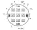
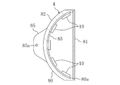
また、発光部4のケース13の形状は、矩形箱状に限られるものではなく、例えば、図25及び図26に示す変形例1のように、ケース80を正面視で円形状としてもよい。ケース80の開口周縁部には、レンズ81が嵌る段差部80aが形成されている。基板固定板82は、ケース80のレンズ81と反対側(後側)へ向けて湾曲する凹面状をなしている。取付基板83は、基板固定板82に沿って凹面状に湾曲している。取付基板83の表面は反射材によりコーティングされている。図25における符号84はコネクタである。また、図26における符号85は、側板部であり、符号85aは挿通孔である。
この変形例1では、白色発光ダイオード実装基板10及び赤色発光ダイオード実装基板11は、光の放射方向がケース80の中心に向くように設けられている。これにより、照射範囲の中心部を明るくすることが可能になる。
また、図27に示す変形例2のように、白色発光ダイオード2、2、…の光の放射方向が白色発光ダイオード実装基板10に対し傾斜した方向となるように、白色発光ダイオード2、2、…を設けるようにしてもよい。これにより、白色発光ダイオード2、2、…の光の放射方向を容易に所望の方向にすることができる。他の発光ダイオードも同様に設けることが可能である。
また、図28に示す変形例3のように、補助照明部6には電池90を設けてもよい。これにより、補助照明部6用の電源コードが不要になる。電池90は、交換できるようにしてもよいし、交換不能にしてもよい。また、電池90は充電池であってもよい。
また、図29に示す変形例4のように支持部材53と、発光部4とを離してもよい。すなわち、支持部材53には、該支持部材53の前面から突出する棒材59が設けられている。棒材59の先端側には、支軸52が設けられており、この支軸52が発光部4の挿通孔14aに挿通している。この変形例4のように、発光部4を支持部材53から離すことによって、発光部4の可動範囲が支持部材53により制限され難くなり、発光部4の可動範囲を拡大できる。また、発光部4で発する発光ダイオード2、3の熱が医師Aに伝わり難くなる。
上記変形例4では、発光部4に操作棒75が着脱可能に取り付けられている。操作棒75は、発光部4に形成したねじ孔(図示せず)にねじ込むか、発光部4に形成した嵌入孔(図示せず)に嵌入させることによって取り付けられるようになっている。医師Aは、操作棒75を持って発光部4の角度を容易に変更することができる。角度を変更した後に操作棒75を発光部4から取り外すことで、操作棒75が手技の邪魔になることはない。操作棒75は、滅菌処理しておくのが好ましい。操作棒75の取付部位は発光部4の下側が好ましいが、上側であってもよい。操作棒75は、実施形態2の左側発光ダイオード取付部4b及び右側発光ダイオード取付部4cに設けることもできる。
また、補助照明部6を発光部4や固定部5とは別に包装して販売することも可能である。
また、発光部4に、傾きを検出する傾き検出センサと、発光ダイオード2、3を制御する制御部とを設け、傾き検出センサの出力信号に基づいて発光ダイオード2、3を制御するようにしてもよい。具体的には、医師Aが下を向いて手技を行っているときには発光ダイオード2、3を点灯させ、一方、医師Aが正面を向いたときや上を向いたときには発光ダイオード2、3の一部または全部消灯させるか、発光ダイオード2、3を暗く点灯させる。これにより、医師Aの正面に位置する者がまぶしさを感じるのを抑制できるとともに、電池の消耗も抑制できる。
また、発光部4の前面にシャッター装置を設けておき、このシャッター装置を傾き検出センサの出力信号に基づいて制御してもよい。具体的には、医師Aが下を向いて手技を行っているときには発光部4を覆わないようにシャッター装置を制御する。一方、医師Aが正面を向いたときや上を向いたときには、シャッター装置により発光部4の前面の全て、または一部を覆う。
また、上記実施形態では、発光体4に発光ダイオード2、3を設けているが、これに限らず、例えば、放電ランプ等を設けてもよい。
以上説明したように、本発明に係る照明装置は、例えば、胸腔や腹腔内の手術に用いることができる。
1 照明装置
2 白色発光ダイオード
3 赤色発光ダイオード
4 発光部
5 固定部
6 補助照明部
7 電源部
10 白色発光ダイオード実装基板
11 赤色発光ダイオード実装基板
23 コネクタ(接続部)
32 針
55、56 ヒンジ機構(照射角度変更部)
60 保護具
A 医師
C 患者
S 胸腔、腹腔
D 創傷部
2 白色発光ダイオード
3 赤色発光ダイオード
4 発光部
5 固定部
6 補助照明部
7 電源部
10 白色発光ダイオード実装基板
11 赤色発光ダイオード実装基板
23 コネクタ(接続部)
32 針
55、56 ヒンジ機構(照射角度変更部)
60 保護具
A 医師
C 患者
S 胸腔、腹腔
D 創傷部
Claims (9)
- 発光部と、該発光部を医療従事者の頭に固定するための固定部とを備えていることを特徴とする照明装置。
- 請求項1に記載の照明装置において、
発光部は、白色発光ダイオードと赤色発光ダイオードとを有していることを特徴とする照明装置。 - 請求項1または2に記載の照明装置において、
発光部は、緑色発光ダイオードと青色発光ダイオードとの少なくとも一方を有していることを特徴とする照明装置。 - 請求項1から3のいずれか1つに記載の照明装置において、
発光部は、赤外線を放射する発光ダイオードを有していることを特徴とする照明装置。 - 請求項2または3に記載の照明装置において、
発光部は、発光ダイオードが着脱される接続部を有していることを特徴とする照明装置。 - 請求項1から5のいずれか1つに記載の照明装置において、
人の胸腔または腹腔内に配置される補助照明部を備えていることを特徴とする照明装置。 - 請求項6に記載の照明装置において、
人の体表側組織が切開されて形成された創傷部を保護する保護具に補助照明部が取り付けられていることを特徴とする照明装置。 - 請求項6に記載の照明装置において、
補助照明部には、人の組織に刺すための針が設けられていることを特徴とする照明装置。 - 請求項1に記載の照明装置において、
光の照射角度を変更する照射角度変更部を備えていることを特徴とする照明装置。
Priority Applications (3)
| Application Number | Priority Date | Filing Date | Title |
|---|---|---|---|
| JP2010520778A JP5642545B2 (ja) | 2008-07-15 | 2009-07-15 | 照明装置 |
| US13/054,310 US9366401B2 (en) | 2008-07-15 | 2009-07-15 | Lighting system |
| EP09797713.6A EP2314247A4 (en) | 2008-07-15 | 2009-07-15 | ILLUMINATION DEVICE |
Applications Claiming Priority (2)
| Application Number | Priority Date | Filing Date | Title |
|---|---|---|---|
| JP2008183359 | 2008-07-15 | ||
| JP2008-183359 | 2008-07-15 |
Publications (1)
| Publication Number | Publication Date |
|---|---|
| WO2010007785A1 true WO2010007785A1 (ja) | 2010-01-21 |
Family
ID=41550195
Family Applications (1)
| Application Number | Title | Priority Date | Filing Date |
|---|---|---|---|
| PCT/JP2009/003348 WO2010007785A1 (ja) | 2008-07-15 | 2009-07-15 | 照明装置 |
Country Status (4)
| Country | Link |
|---|---|
| US (1) | US9366401B2 (ja) |
| EP (1) | EP2314247A4 (ja) |
| JP (1) | JP5642545B2 (ja) |
| WO (1) | WO2010007785A1 (ja) |
Cited By (18)
| Publication number | Priority date | Publication date | Assignee | Title |
|---|---|---|---|---|
| WO2012023090A1 (en) * | 2010-08-17 | 2012-02-23 | Koninklijke Philips Electronics N.V. | Surgical lamp for broadband and narrowband illumination |
| JP4937423B1 (ja) * | 2010-11-17 | 2012-05-23 | 正一 中村 | 医療用光源装置 |
| WO2012096077A1 (ja) * | 2011-01-13 | 2012-07-19 | 日本エー・シー・ピー株式会社 | 医療用光源装置 |
| CN103330626A (zh) * | 2013-06-30 | 2013-10-02 | 戴伟 | 胸外手术辅助架 |
| JP2014500594A (ja) * | 2010-11-17 | 2014-01-09 | インテグラ・ライフサイエンシーズ・コーポレイション | 装着型ヘッドライトデバイスおよび関連の方法 |
| JP2014511007A (ja) * | 2011-04-01 | 2014-05-01 | 上海広茂達光藝科技股▲分▼有限公司 | Led投影照明装置 |
| JP2015019886A (ja) * | 2013-07-19 | 2015-02-02 | 合同会社ジャパン・メディカル・クリエーティブ | 額帯灯型無影灯 |
| JP2015046276A (ja) * | 2013-08-28 | 2015-03-12 | 株式会社エム・エイチ・シー | 携帯用ライト |
| WO2015056911A1 (ko) * | 2013-10-16 | 2015-04-23 | 김기천 | 두 광원 사이에 카메라 대물렌즈가 설치되는 헤드램프 카메라시스템 |
| JP2017504458A (ja) * | 2014-01-28 | 2017-02-09 | インブイティ・インコーポレイテッド | ドロップイン外科手術用照明器 |
| JP6300424B1 (ja) * | 2017-05-30 | 2018-03-28 | 俊寛 都筑 | 額帯用観察撮像装置 |
| JPWO2018003169A1 (ja) * | 2016-06-30 | 2018-11-01 | 株式会社島津製作所 | イメージング装置 |
| KR20180126502A (ko) * | 2017-04-19 | 2018-11-27 | 다이요 쇼우지 가부시끼가이샤 | 헤드부 장착형 조명 장치 |
| JP2020509811A (ja) * | 2017-03-01 | 2020-04-02 | ディグニティ・ヘルス | 手術照明のための装置及び方法 |
| USD884236S1 (en) | 2018-10-04 | 2020-05-12 | Integra Lifesciences Corporation | Wearable headgear device |
| US10724716B2 (en) | 2018-10-04 | 2020-07-28 | Integra Lifesciences Corporation | Head wearable devices and methods |
| USD901737S1 (en) | 2018-10-04 | 2020-11-10 | Integra Lifesciences Corporation | Wearable headgear device |
| USD976462S1 (en) * | 2021-11-08 | 2023-01-24 | Fuguang Liu | Lamp |
Families Citing this family (7)
| Publication number | Priority date | Publication date | Assignee | Title |
|---|---|---|---|---|
| US20120327643A1 (en) * | 2011-06-22 | 2012-12-27 | Nguyen Ronald C | Hands-free lighting system |
| ITGE20110112A1 (it) * | 2011-10-17 | 2013-04-18 | Michele Iurilli | Occhiale comprendente mezzi di illuminazione del campo visivo |
| US9498641B2 (en) * | 2012-03-05 | 2016-11-22 | Blue Water Innovations, Llc | Fat reducing device and method utilizing optical emitters |
| RU2665121C2 (ru) | 2013-05-03 | 2018-08-28 | Филипс Лайтинг Холдинг Б.В. | Источник света с настроенным спектральным распределением |
| CA2825559C (en) * | 2013-08-30 | 2017-02-28 | Mckenn Enterprises Inc. | Portable vanity lighting system |
| FR3017691B1 (fr) * | 2014-02-14 | 2019-06-28 | Zedel | Lampe electrique portative dotee d'un systeme de communication sans-fil |
| US20190390844A1 (en) * | 2018-06-22 | 2019-12-26 | Optimal Ventures, LLC | LED Headlamp with Multiple Power Input Capability |
Citations (8)
| Publication number | Priority date | Publication date | Assignee | Title |
|---|---|---|---|---|
| WO2003019072A1 (fr) * | 2001-08-23 | 2003-03-06 | Yukiyasu Okumura | Eclairage par del a temperature de couleur reglable |
| JP3098051U (ja) * | 2003-05-26 | 2004-02-19 | 株式会社精工タカネ | 医療用照明器具 |
| JP2005058440A (ja) * | 2003-08-12 | 2005-03-10 | Junichi Shimada | Led付開創器 |
| JP2005211409A (ja) * | 2004-01-30 | 2005-08-11 | Stanley Electric Co Ltd | 手術用胸腔内照明装置およびそれを使用した胸腔内照明方法 |
| JP2005279255A (ja) * | 2004-03-05 | 2005-10-13 | Junichi Shimada | 照明装置、フィルタ装置、画像表示装置 |
| JP2005304599A (ja) * | 2004-04-19 | 2005-11-04 | Morita Mfg Co Ltd | 頭部装着診断用光照射装置 |
| JP2006147482A (ja) | 2004-11-24 | 2006-06-08 | Shinwakai Yachiyo Byoin | 無影灯 |
| WO2007014629A1 (de) * | 2005-08-02 | 2007-02-08 | Berchtold Holding Gmbh | Operationsleuchte |
Family Cites Families (23)
| Publication number | Priority date | Publication date | Assignee | Title |
|---|---|---|---|---|
| US2539104A (en) * | 1945-07-26 | 1951-01-23 | Rodel Arthur | Forehead lamps, particularly for medical purposes |
| US2893379A (en) * | 1956-02-15 | 1959-07-07 | Henry A Springer | Illuminating devices |
| US4234910A (en) * | 1978-03-20 | 1980-11-18 | Price Linda D | Head-supported illumination device |
| JP3022512U (ja) | 1995-09-08 | 1996-03-26 | 株式会社モリタ製作所 | 頭部または顔面装着型医療用照明装置 |
| US5722762A (en) * | 1996-07-18 | 1998-03-03 | Soll; David B. | Illumination device for mounting on the head of a user |
| US7306559B2 (en) * | 1997-07-02 | 2007-12-11 | Lumitex, Inc. | Illuminated surgical retractor |
| US20050099824A1 (en) * | 2000-08-04 | 2005-05-12 | Color Kinetics, Inc. | Methods and systems for medical lighting |
| US6554444B2 (en) * | 2000-03-13 | 2003-04-29 | Kansai Technology Licensing Organization Co., Ltd. | Gazing point illuminating device |
| US20030067769A1 (en) * | 2001-10-10 | 2003-04-10 | Scott Gilpin | Multiple LED light source |
| US7223233B2 (en) * | 2002-08-02 | 2007-05-29 | Warsaw Orthopedic, Inc. | Systems and techniques for illuminating a surgical space |
| US6877875B2 (en) * | 2002-11-06 | 2005-04-12 | Zen Design Group, Ltd | Canted head-mounted light |
| US6908208B1 (en) * | 2004-01-02 | 2005-06-21 | Raymond Quentin Hyde | Light to be worn on head |
| ATE357627T1 (de) * | 2004-02-28 | 2007-04-15 | Trumpf Kreuzer Med Sys Gmbh | Operationsleuchte |
| US7192151B2 (en) * | 2004-12-21 | 2007-03-20 | Depuy Products, Inc. | Light array for a surgical helmet |
| WO2006074525A1 (en) * | 2005-01-14 | 2006-07-20 | Topstore Pty Ltd | Dental illumination device and method |
| CN102934984B (zh) * | 2005-04-01 | 2015-11-18 | 韦尔奇阿林公司 | 阴道窥镜 |
| US7871375B2 (en) * | 2005-04-05 | 2011-01-18 | Medical Vision Industries, Inc. | LED lighting apparatus and method of using same for illumination of a body cavity |
| US8789962B2 (en) * | 2005-10-27 | 2014-07-29 | Vikon Surgical, Llc | Surgical headlight |
| US7490949B2 (en) * | 2006-12-14 | 2009-02-17 | Medinis David M | Surgical headlamp |
| US7699486B1 (en) * | 2007-10-29 | 2010-04-20 | Edward Beiner | Illuminated eyeglass assembly |
| WO2009111792A2 (en) * | 2008-03-07 | 2009-09-11 | Alpha Med-Surge Inc. | Tunable light controller |
| US8900138B2 (en) * | 2009-11-05 | 2014-12-02 | James P. Horvath | Headlight apparatus and method |
| DE102009053795A1 (de) * | 2009-11-18 | 2011-05-26 | Dräger Medical GmbH | Ansteuervorrichtung für Operationsleuchten |
-
2009
- 2009-07-15 US US13/054,310 patent/US9366401B2/en active Active
- 2009-07-15 WO PCT/JP2009/003348 patent/WO2010007785A1/ja active Application Filing
- 2009-07-15 JP JP2010520778A patent/JP5642545B2/ja active Active
- 2009-07-15 EP EP09797713.6A patent/EP2314247A4/en not_active Withdrawn
Patent Citations (8)
| Publication number | Priority date | Publication date | Assignee | Title |
|---|---|---|---|---|
| WO2003019072A1 (fr) * | 2001-08-23 | 2003-03-06 | Yukiyasu Okumura | Eclairage par del a temperature de couleur reglable |
| JP3098051U (ja) * | 2003-05-26 | 2004-02-19 | 株式会社精工タカネ | 医療用照明器具 |
| JP2005058440A (ja) * | 2003-08-12 | 2005-03-10 | Junichi Shimada | Led付開創器 |
| JP2005211409A (ja) * | 2004-01-30 | 2005-08-11 | Stanley Electric Co Ltd | 手術用胸腔内照明装置およびそれを使用した胸腔内照明方法 |
| JP2005279255A (ja) * | 2004-03-05 | 2005-10-13 | Junichi Shimada | 照明装置、フィルタ装置、画像表示装置 |
| JP2005304599A (ja) * | 2004-04-19 | 2005-11-04 | Morita Mfg Co Ltd | 頭部装着診断用光照射装置 |
| JP2006147482A (ja) | 2004-11-24 | 2006-06-08 | Shinwakai Yachiyo Byoin | 無影灯 |
| WO2007014629A1 (de) * | 2005-08-02 | 2007-02-08 | Berchtold Holding Gmbh | Operationsleuchte |
Non-Patent Citations (1)
| Title |
|---|
| See also references of EP2314247A4 |
Cited By (44)
| Publication number | Priority date | Publication date | Assignee | Title |
|---|---|---|---|---|
| WO2012023090A1 (en) * | 2010-08-17 | 2012-02-23 | Koninklijke Philips Electronics N.V. | Surgical lamp for broadband and narrowband illumination |
| US9057492B2 (en) | 2010-08-17 | 2015-06-16 | Koninklijke Philips N.V. | Surgical lamp for broadband and narrowband illumination |
| US8899774B2 (en) | 2010-11-17 | 2014-12-02 | Integra Lifesciences Corporation | Wearable headlight devices and related methods |
| JP2014500594A (ja) * | 2010-11-17 | 2014-01-09 | インテグラ・ライフサイエンシーズ・コーポレイション | 装着型ヘッドライトデバイスおよび関連の方法 |
| CN102762914A (zh) * | 2010-11-17 | 2012-10-31 | 中村正一 | 医疗用光源装置 |
| EP2527716A1 (en) * | 2010-11-17 | 2012-11-28 | Nakamura, Shoichi | Medical light-source device |
| US10253964B2 (en) | 2010-11-17 | 2019-04-09 | Integra Lifesciences Corporation | Wearable headlight devices and related methods |
| EP2527716A4 (en) * | 2010-11-17 | 2014-01-01 | Shoichi Nakamura | MEDICAL LIGHT SOURCE DEVICE |
| US9400101B2 (en) | 2010-11-17 | 2016-07-26 | Integra Lifesciences Corporation | Wearable headlight devices and related methods |
| US8920013B2 (en) | 2010-11-17 | 2014-12-30 | Acp Japan Co., Ltd. | Medical light-source device |
| WO2012066808A1 (ja) * | 2010-11-17 | 2012-05-24 | 日本エー・シー・ピー株式会社 | 医療用光源装置 |
| JP4937423B1 (ja) * | 2010-11-17 | 2012-05-23 | 正一 中村 | 医療用光源装置 |
| JP5529978B2 (ja) * | 2011-01-13 | 2014-06-25 | 正一 中村 | 医療用光源装置 |
| WO2012096077A1 (ja) * | 2011-01-13 | 2012-07-19 | 日本エー・シー・ピー株式会社 | 医療用光源装置 |
| KR101347899B1 (ko) * | 2011-01-13 | 2014-01-06 | 에이씨피 저팬 가부시키가이샤 | 의료용 광원 장치 |
| US9215782B2 (en) | 2011-01-13 | 2015-12-15 | Acp Japan Co., Ltd. | Medical light source device |
| JP2014511007A (ja) * | 2011-04-01 | 2014-05-01 | 上海広茂達光藝科技股▲分▼有限公司 | Led投影照明装置 |
| CN103330626A (zh) * | 2013-06-30 | 2013-10-02 | 戴伟 | 胸外手术辅助架 |
| JP2015019886A (ja) * | 2013-07-19 | 2015-02-02 | 合同会社ジャパン・メディカル・クリエーティブ | 額帯灯型無影灯 |
| JP2015046276A (ja) * | 2013-08-28 | 2015-03-12 | 株式会社エム・エイチ・シー | 携帯用ライト |
| WO2015056911A1 (ko) * | 2013-10-16 | 2015-04-23 | 김기천 | 두 광원 사이에 카메라 대물렌즈가 설치되는 헤드램프 카메라시스템 |
| JP2017504458A (ja) * | 2014-01-28 | 2017-02-09 | インブイティ・インコーポレイテッド | ドロップイン外科手術用照明器 |
| JPWO2018003169A1 (ja) * | 2016-06-30 | 2018-11-01 | 株式会社島津製作所 | イメージング装置 |
| JP2020509811A (ja) * | 2017-03-01 | 2020-04-02 | ディグニティ・ヘルス | 手術照明のための装置及び方法 |
| JP7406200B2 (ja) | 2017-03-01 | 2023-12-27 | ディグニティ・ヘルス | 手術照明のための装置及び方法 |
| KR20180126502A (ko) * | 2017-04-19 | 2018-11-27 | 다이요 쇼우지 가부시끼가이샤 | 헤드부 장착형 조명 장치 |
| DE112017007464T5 (de) | 2017-04-19 | 2019-12-24 | Taiyo Corporation | Am Kopf befestigbare Beleuchtungseinrichtung |
| DE112017007464B4 (de) | 2017-04-19 | 2023-06-29 | Taiyo Corporation | Am Kopf befestigbare Beleuchtungseinrichtung |
| KR102168982B1 (ko) * | 2017-04-19 | 2020-10-22 | 다이요 쇼우지 가부시끼가이샤 | 헤드부 장착형 조명 장치 |
| JP2018201574A (ja) * | 2017-05-30 | 2018-12-27 | 俊寛 都筑 | 額帯用観察撮像装置 |
| JP6300424B1 (ja) * | 2017-05-30 | 2018-03-28 | 俊寛 都筑 | 額帯用観察撮像装置 |
| US11067267B2 (en) | 2018-10-04 | 2021-07-20 | Integra Lifesciences Corporation | Head wearable devices and methods |
| US10830428B2 (en) | 2018-10-04 | 2020-11-10 | Integra Lifesciences Corporation | Head wearable devices and methods |
| USD901737S1 (en) | 2018-10-04 | 2020-11-10 | Integra Lifesciences Corporation | Wearable headgear device |
| USD935074S1 (en) | 2018-10-04 | 2021-11-02 | Integra Lifesciences Corporation | Wearable headgear device |
| US11255533B2 (en) | 2018-10-04 | 2022-02-22 | Integra Lifesciences Corporation | Head wearable devices and methods |
| US11268686B2 (en) | 2018-10-04 | 2022-03-08 | Integra Lifesciences Corporation | Head wearable devices and methods |
| US11555605B2 (en) | 2018-10-04 | 2023-01-17 | Integra Lifesciences Corporation | Head wearable devices and methods |
| US11635198B2 (en) | 2018-10-04 | 2023-04-25 | Integra Lifesciences Corporation | Head wearable devices and methods |
| US11674681B2 (en) | 2018-10-04 | 2023-06-13 | Integra Lifesciences Corporation | Head wearable devices and methods |
| US10724716B2 (en) | 2018-10-04 | 2020-07-28 | Integra Lifesciences Corporation | Head wearable devices and methods |
| US11835211B2 (en) | 2018-10-04 | 2023-12-05 | Integra Lifesciences Corporation | Head wearable devices and methods |
| USD884236S1 (en) | 2018-10-04 | 2020-05-12 | Integra Lifesciences Corporation | Wearable headgear device |
| USD976462S1 (en) * | 2021-11-08 | 2023-01-24 | Fuguang Liu | Lamp |
Also Published As
| Publication number | Publication date |
|---|---|
| JP5642545B2 (ja) | 2014-12-17 |
| JPWO2010007785A1 (ja) | 2012-01-05 |
| US9366401B2 (en) | 2016-06-14 |
| EP2314247A1 (en) | 2011-04-27 |
| US20110160541A1 (en) | 2011-06-30 |
| EP2314247A4 (en) | 2016-03-02 |
Similar Documents
| Publication | Publication Date | Title |
|---|---|---|
| JP5642545B2 (ja) | 照明装置 | |
| US11219566B2 (en) | Multimodality medical procedure mattress-based device | |
| JP5784308B2 (ja) | 手術用照明システム | |
| EP2659829B1 (en) | Device for white balancing and applying an anti-fog agent to medical videoscopes prior to medical procedures | |
| JP5756161B2 (ja) | 開創器 | |
| US7871375B2 (en) | LED lighting apparatus and method of using same for illumination of a body cavity | |
| JP4769948B2 (ja) | 医療用発光装置 | |
| US20120101342A1 (en) | Pediatric tissue illuminator | |
| CN107835670A (zh) | 用于辅助开放式手术的装置和套件 | |
| WO2006039024A3 (en) | Disposable sterile surgical drape and attached instruments | |
| US6496718B1 (en) | Body cavity light using diffuse light source | |
| US20070081358A1 (en) | Medical Illumination Device with a Base | |
| US20100156318A1 (en) | Light Source System For Use With Medical Devices | |
| US20070081348A1 (en) | Medical Illumination Device with Sterile Packaging | |
| CN207132236U (zh) | 一种无害紫外杀菌手术无影灯 | |
| TWI754641B (zh) | 血氧計裝置及具有此裝置之血氧計系統 | |
| CN216019283U (zh) | 一种带有光源的面部防护罩 | |
| KR20130034071A (ko) | 의료기기에 탈 부착되는 조명장치 | |
| WO2024076391A1 (en) | Body cavity light based treatment devices | |
| CN109140293B (zh) | 一种内腔辅助探照灯 | |
| KR20070018951A (ko) | 구강 스코프 및 주변 광 관리 시스템(alms)을 포함하는질병 탐지 시스템 및 방법 | |
| GB2620030A (en) | A light assembly | |
| CN107448878A (zh) | 一种无害紫外杀菌手术无影灯 |
Legal Events
| Date | Code | Title | Description |
|---|---|---|---|
| 121 | Ep: the epo has been informed by wipo that ep was designated in this application |
Ref document number: 09797713 Country of ref document: EP Kind code of ref document: A1 |
|
| WWE | Wipo information: entry into national phase |
Ref document number: 2010520778 Country of ref document: JP |
|
| NENP | Non-entry into the national phase |
Ref country code: DE |
|
| WWE | Wipo information: entry into national phase |
Ref document number: 2009797713 Country of ref document: EP |
|
| WWE | Wipo information: entry into national phase |
Ref document number: 13054310 Country of ref document: US |