WO2010007702A1 - ボンディング良否判定方法およびボンディング良否判定装置ならびにボンディング装置 - Google Patents
ボンディング良否判定方法およびボンディング良否判定装置ならびにボンディング装置 Download PDFInfo
- Publication number
- WO2010007702A1 WO2010007702A1 PCT/JP2008/072814 JP2008072814W WO2010007702A1 WO 2010007702 A1 WO2010007702 A1 WO 2010007702A1 JP 2008072814 W JP2008072814 W JP 2008072814W WO 2010007702 A1 WO2010007702 A1 WO 2010007702A1
- Authority
- WO
- WIPO (PCT)
- Prior art keywords
- bonding
- signal
- ultrasonic horn
- load
- ultrasonic
- Prior art date
- Legal status (The legal status is an assumption and is not a legal conclusion. Google has not performed a legal analysis and makes no representation as to the accuracy of the status listed.)
- Ceased
Links
Images






Classifications
-
- B—PERFORMING OPERATIONS; TRANSPORTING
- B23—MACHINE TOOLS; METAL-WORKING NOT OTHERWISE PROVIDED FOR
- B23K—SOLDERING OR UNSOLDERING; WELDING; CLADDING OR PLATING BY SOLDERING OR WELDING; CUTTING BY APPLYING HEAT LOCALLY, e.g. FLAME CUTTING; WORKING BY LASER BEAM
- B23K20/00—Non-electric welding by applying impact or other pressure, with or without the application of heat, e.g. cladding or plating
- B23K20/002—Non-electric welding by applying impact or other pressure, with or without the application of heat, e.g. cladding or plating specially adapted for particular articles or work
- B23K20/004—Wire welding
- B23K20/005—Capillary welding
- B23K20/007—Ball bonding
-
- B—PERFORMING OPERATIONS; TRANSPORTING
- B23—MACHINE TOOLS; METAL-WORKING NOT OTHERWISE PROVIDED FOR
- B23K—SOLDERING OR UNSOLDERING; WELDING; CLADDING OR PLATING BY SOLDERING OR WELDING; CUTTING BY APPLYING HEAT LOCALLY, e.g. FLAME CUTTING; WORKING BY LASER BEAM
- B23K31/00—Processes relevant to this subclass, specially adapted for particular articles or purposes, but not covered by any single one of main groups B23K1/00 - B23K28/00
- B23K31/12—Processes relevant to this subclass, specially adapted for particular articles or purposes, but not covered by any single one of main groups B23K1/00 - B23K28/00 relating to investigating the properties, e.g. the weldability, of materials
- B23K31/125—Weld quality monitoring
-
- B—PERFORMING OPERATIONS; TRANSPORTING
- B23—MACHINE TOOLS; METAL-WORKING NOT OTHERWISE PROVIDED FOR
- B23K—SOLDERING OR UNSOLDERING; WELDING; CLADDING OR PLATING BY SOLDERING OR WELDING; CUTTING BY APPLYING HEAT LOCALLY, e.g. FLAME CUTTING; WORKING BY LASER BEAM
- B23K2101/00—Articles made by soldering, welding or cutting
- B23K2101/36—Electric or electronic devices
- B23K2101/42—Printed circuits
-
- H—ELECTRICITY
- H10—SEMICONDUCTOR DEVICES; ELECTRIC SOLID-STATE DEVICES NOT OTHERWISE PROVIDED FOR
- H10W—GENERIC PACKAGES, INTERCONNECTIONS, CONNECTORS OR OTHER CONSTRUCTIONAL DETAILS OF DEVICES COVERED BY CLASS H10
- H10W72/00—Interconnections or connectors in packages
- H10W72/071—Connecting or disconnecting
- H10W72/0711—Apparatus therefor
- H10W72/07141—Means for applying energy, e.g. ovens or lasers
-
- H—ELECTRICITY
- H10—SEMICONDUCTOR DEVICES; ELECTRIC SOLID-STATE DEVICES NOT OTHERWISE PROVIDED FOR
- H10W—GENERIC PACKAGES, INTERCONNECTIONS, CONNECTORS OR OTHER CONSTRUCTIONAL DETAILS OF DEVICES COVERED BY CLASS H10
- H10W72/00—Interconnections or connectors in packages
- H10W72/071—Connecting or disconnecting
- H10W72/0711—Apparatus therefor
- H10W72/07183—Means for monitoring
-
- H—ELECTRICITY
- H10—SEMICONDUCTOR DEVICES; ELECTRIC SOLID-STATE DEVICES NOT OTHERWISE PROVIDED FOR
- H10W—GENERIC PACKAGES, INTERCONNECTIONS, CONNECTORS OR OTHER CONSTRUCTIONAL DETAILS OF DEVICES COVERED BY CLASS H10
- H10W72/00—Interconnections or connectors in packages
- H10W72/071—Connecting or disconnecting
- H10W72/075—Connecting or disconnecting of bond wires
- H10W72/07531—Techniques
- H10W72/07532—Compression bonding, e.g. thermocompression bonding
- H10W72/07533—Ultrasonic bonding, e.g. thermosonic bonding
-
- H—ELECTRICITY
- H10—SEMICONDUCTOR DEVICES; ELECTRIC SOLID-STATE DEVICES NOT OTHERWISE PROVIDED FOR
- H10W—GENERIC PACKAGES, INTERCONNECTIONS, CONNECTORS OR OTHER CONSTRUCTIONAL DETAILS OF DEVICES COVERED BY CLASS H10
- H10W72/00—Interconnections or connectors in packages
- H10W72/50—Bond wires
- H10W72/551—Materials of bond wires
- H10W72/552—Materials of bond wires comprising metals or metalloids, e.g. silver
Definitions
- the present invention relates to a bonding quality determination method for a bonding apparatus, a bonding quality determination apparatus used in the bonding apparatus, and a structure of a bonding apparatus that performs bonding quality determination.
- the wire bonding apparatus In a manufacturing process of a semiconductor device, a wire bonding apparatus that connects a pad that is an electrode of a semiconductor chip and a lead that is an electrode of a lead frame with a wire that is a thin metal wire is often used.
- the wire bonding apparatus includes a bonding arm rotated by a drive motor, an ultrasonic horn attached to the bonding arm, a capillary attached to the tip of the ultrasonic horn, and an ultrasonic transducer attached to the ultrasonic horn.
- the initial ball formed at the tip of the wire inserted into the capillary collides with the pad at a certain speed, and then is pressed against the pad with a constant load to be pressed against the pad to become a pressed ball.
- the wire and capillary vibrate in the pressing direction during the subsequent pressing period with a constant load due to the impact, and the pressing load fluctuates due to this vibration, resulting in variations in the shape of the pressure-bonded ball and the diameter of the pressure-bonded ball. May occur.
- the pressing load fluctuates to cause bonding failure.
- an encoder for detecting the displacement in the height direction of the capillary is provided in the bonding head, the detection output of this encoder is fed back to the control apparatus, and the output of the drive motor is controlled to prevent fluctuations in the pressing load. To be done.
- the encoder cannot directly detect the pressing load of the wire, the feedback of the encoder output cannot sufficiently suppress the fluctuation of the pressing load.
- the bonding of the semiconductor chip and the substrate is performed by sequentially connecting the pads of the plurality of semiconductor chips and the leads of the substrate.
- the bonding arm and the capillary are not loosened or worn, and even if the pressing load with which the capillary presses the pad is controlled to a predetermined value, defective bonding such as abnormal ball collapse or chip destruction may occur.
- the conventional technique described in Patent Document 1 or Patent Document 2 cannot detect a bonding failure in the middle of bonding, it is performed after bonding a plurality of pads on a semiconductor chip and a plurality of leads on a substrate. Bonding defects cannot be found until the visual inspection process of the bonding part.
- An object of the present invention is to determine whether bonding is good or bad during bonding.
- the bonding quality determination method of the present invention includes a base part, an ultrasonic horn that resonates with vibration of an ultrasonic vibrator and longitudinally vibrates in a longitudinal direction, a bonding tool attached to an antinode of the vibration of the ultrasonic horn, Includes a flange provided at the vibration node of the horn and a flange mounting surface to which the flange of the ultrasonic horn is fixed.
- the tip of the bonding tool is rotatably attached to the base so as to move in the direction of contact with the object to be bonded.
- a load sensor attached between the rotation center of the bonding arm and the flange mounting surface by being offset from the longitudinal central axis of the ultrasonic horn in the direction of contact with and away from the object to be bonded.
- the bonding failure is determined when the impact load is larger than a predetermined threshold, and a signal in the resonance frequency band specific to the ultrasonic horn is cut off.
- an ultrasonic transducer that does not include a signal in the frequency band of the resonance frequency unique to the ultrasonic horn from the load signal detected by the load sensor with a filter that passes a signal in a frequency band lower than the resonance frequency of the ultrasonic transducer.
- the bonding quality determination apparatus of the present invention includes a base unit, an ultrasonic horn that resonates with the vibration of the ultrasonic vibrator and longitudinally vibrates in the longitudinal direction, a bonding tool attached to the antinode of the vibration of the ultrasonic horn, Includes a flange provided at the vibration node of the horn and a flange mounting surface to which the flange of the ultrasonic horn is fixed.
- the tip of the bonding tool is rotatably attached to the base so as to move in the direction of contact with the object to be bonded.
- a load sensor attached between the rotation center of the bonding arm and the flange mounting surface by being offset from the longitudinal central axis of the ultrasonic horn in the direction of contact with and away from the object to be bonded.
- This is a bonding pass / fail judgment device used in the device, and has a resonance circumference unique to an ultrasonic horn. From the load signal detected by the load sensor using a filter that blocks signals in several frequency bands and allows signals in a frequency band lower than the resonance frequency of the ultrasonic transducer to pass through to the resonance frequency band specific to the ultrasonic horn.
- the bonding apparatus of the present invention includes a base unit, an ultrasonic horn that resonates with the vibration of the ultrasonic vibrator and longitudinally vibrates in the longitudinal direction, a bonding tool attached to the antinode of the vibration of the ultrasonic horn, and an ultrasonic horn Includes a flange provided at the vibration node and a flange mounting surface to which the flange of the ultrasonic horn is fixed, and is rotatably attached to the base so that the tip of the bonding tool can be moved toward and away from the bonding target Bonding arm, load sensor that is offset between the center axis of the ultrasonic horn in the longitudinal direction with respect to the object to be bonded and attached between the rotation center of the bonding arm and the flange mounting surface, and judgment of bonding quality And a control unit that performs the control.
- Filter means for blocking signals in the frequency band of the frequency and passing signals in a frequency band lower than the resonance frequency of the ultrasonic transducer, and a bonding target applied to the bonding tool by a load sensor during bonding Signal extraction that continuously detects the load signal and extracts a signal in the frequency band lower than the resonance frequency of the ultrasonic transducer that does not include the signal in the resonance frequency band specific to the ultrasonic horn from the load signal by the filter means And a determination means for determining whether the bonding is good or not based on the magnitude of the impact load, with the maximum value of the signal extracted by the signal extraction means as an impact load.
- the present invention has an effect that the quality of bonding can be determined in the middle of bonding.
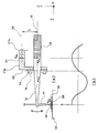
- the wire bonding apparatus 10 to which the bonding quality determination apparatus 50 of this embodiment is attached includes a bonding head 11 that is a base portion, an ultrasonic vibrator 13, an ultrasonic horn 12, a bonding A capillary 17 as a tool, a flange 14 provided on the ultrasonic horn 12, a bonding arm 21, a load sensor 31, a drive motor 45, a control unit 60, a semiconductor chip 34 and a substrate 35 to be bonded are provided. And a bonding stage 33 for adsorbing and fixing.
- the bonding head 11 is provided with a drive motor 45 that rotationally drives the bonding arm 21.
- the ultrasonic transducer 13 is a superposition of a plurality of piezoelectric elements, and is attached to the rear end side of the ultrasonic horn 12.
- a capillary 17 is attached to the tip of the ultrasonic horn 12.
- a flange 14 is provided at a position to be a vibration node of the ultrasonic horn 12 to be described later, and the flange 14 is fixed to a flange mounting surface 22 at the tip of the bonding arm 21 by a bolt 16.
- the bonding arm 21 is rotatably attached around a rotation shaft 30 provided on the bonding head 11.
- the rotation center 43 of the bonding arm 21 is on the same plane as the surface of the substrate 35 adsorbed on the bonding stage 33 or the surface of the semiconductor chip 34 attached to the substrate 35.
- the bonding arm 21 is a substantially rectangular parallelepiped extending in the direction of the central axis 15 of the ultrasonic horn 12, and has a front end side portion 21 a having a flange mounting surface 22 and a rear end side portion 21 b including a rotation center 43.
- the portion 21 a and the rear end side portion 21 b are connected by a thin plate-like connection portion 24 provided at a height direction position (Z direction position) including the central axis 15 of the ultrasonic horn 12.
- thin slits 23 and 25 are provided between the front end side portion 21a and the rear end side portion 21b of the bonding arm 21.
- a groove 26 for attaching the load sensor 31 is provided on the upper side in the Z direction opposite to the bonding surface 41 of the bonding arm 21.
- the groove 26 is provided between the front end side portion 21a and the rear end side portion 21b of the bonding arm 21 so as to face each other.
- the load sensor 31 attached to the groove 26 is sandwiched between the front end portion 21a and the rear end portion 21b by a screw 27 screwed from the bonding arm front end portion 21a toward the rear end portion 21b. It is configured to be pressurized.
- the load sensor 31 is attached such that the center axis 28 is offset from the center axis 15 of the ultrasonic horn 12 by a distance L in the Z direction, which is the contact / separation direction between the bonding surface 41 and the tip 17a of the capillary 17.
- This distance L is larger than the width of the flange 14 in the Z direction, and can be provided with a large rigidity against the bending force applied from the capillary 17 to the ultrasonic horn 12.
- the load sensor 31 is attached to the center portion in the width direction of the bonding arm 21, and the screws 27 are provided on both sides of the load sensor 31. Further, as shown in FIG. 2B, a recess 29 in which the ultrasonic horn 12 and the ultrasonic transducer 13 are accommodated is provided on the bonding surface 41 side of the bonding arm 21.
- the ultrasonic horn 12 resonates in the longitudinal direction, which is the direction along the central axis 15, and vibrates longitudinally by the ultrasonic vibrator 13.
- longitudinal vibration refers to vibration in which the direction of vibration and the direction of amplitude are the same.
- the ultrasonic horn 12 includes a rear end to which the ultrasonic transducer 13 is attached and a tip to which the capillary 17 is attached by vibration of the ultrasonic transducer 13 attached to the rear end. , The rear end and the front end vibrate in a resonance mode that becomes an antinode of vibration.
- a flange 14 for fixing the ultrasonic horn 12 to the bonding arm 21 is provided at a vibration node formed between the rear end and the front end, that is, a portion that does not vibrate even in a resonance state.
- the flange 14 is fixed to the flange mounting surface 22 of the bonding arm 21 with bolts 16. Since the flange 14 does not vibrate due to the resonance of the ultrasonic horn 12, the ultrasonic wave due to the resonance of the ultrasonic horn 12 is not transmitted to the flange mounting surface 22 of the bonding arm 21. For this reason, the ultrasonic vibration due to the resonance of the ultrasonic horn 12 is not transmitted to the load sensor 31 provided in the bonding arm 21.
- FIG. 3 is a schematic diagram for explaining the relationship between the bonding arm 21, the ultrasonic horn 12, the flange 14, and the bolt 16.
- the flange 14 extending from the ultrasonic horn 12 in the horizontal and XY directions is vertically arranged. It is written in the direction.
- FIG. 3B schematically shows the amplitude of the ultrasonic horn 12, and the amplitude in the direction of the central axis 15 is described as the amplitude in the direction perpendicular to the central axis 15.
- the bonding quality determination device 50 is connected to a load sensor 31 and includes a low-pass filter therein.
- the low-pass filter has a notch function that allows a signal in a frequency band lower than the resonance frequency f 0 of the ultrasonic transducer 13 to pass and blocks a signal in the frequency band of the resonance frequency f 1 unique to the ultrasonic horn 12. Extracting a signal in a frequency band lower than the resonance frequency f 0 of the ultrasonic transducer 13 that does not include a signal in the frequency band of the resonance frequency f 1 unique to the ultrasonic horn 12 from the signal detected by the load sensor 31. It is configured to be able to.
- the ultrasonic vibrator 13 and the drive motor 45 are connected to the control unit 60, and the output of the ultrasonic vibrator 13, the rotation direction of the drive motor 45, and the output are controlled by a command from the control unit 60.
- the bonding quality determination device 50 is connected to the control unit 60 and configured to output a bonding quality determination signal to the control unit 60.
- the bonding quality determination device 50 and the control unit 60 may be configured as a computer including a CPU, a memory, and the like, or may be configured such that a detection and control system is configured by an electric circuit.
- the control unit 60 shown in FIG. 1 forms the tip of the wire extending from the tip 17a of the capillary 17 into a spherical initial ball 18 by a discharge torch or the like (not shown). Then, the control unit 60 outputs a command for driving the drive motor 45. By this command, the drive motor 45 starts to rotate and starts to lower the capillary 17 toward the semiconductor chip 34. Further, the control unit 60 outputs a command for starting the vibration of the ultrasonic transducer 13. By this command, a voltage capable of outputting a vibration output set in advance corresponding to the bonding condition is applied to the ultrasonic transducer 13. The bonding quality determination device 50 starts accumulating the load signal from the load sensor 31 in the memory.
- the ultrasonic horn 12 Before the initial ball 18 formed at the tip of the capillary 17 comes into contact with the surface of the semiconductor chip 34, the ultrasonic horn 12 resonates with the vibration of the ultrasonic vibrator 13 as shown in FIG. A longitudinal vibration is generated with the front end and the rear end to which the ultrasonic transducer 13 is attached as the antinode of vibration. Since the flange 14 is arranged at the vibration node, it does not vibrate due to the resonance of the ultrasonic horn 12, and the load sensor 31 does not detect the load. However, the ultrasonic horn 12 vibrates minutely at a resonance frequency f 1 inherent in the Z direction due to a collision with the pad during bonding. For this reason, as shown in FIG. 4A, the load sensor 31 detects a minute periodic fluctuation load due to the vibration of the ultrasonic horn 12.
- Bonding arm 21 is accelerated by the drive motor 45, with a predetermined descending speed collides with the pads of the semiconductor chip 34 to the time t 1 in FIG. 4 (a). Then, the pressing load detected by the load sensor 31 increases rapidly. The maximum value F 0 is reached at time t 2 shown in FIG. Thereafter, the control unit 60 controls the drive motor 45 so that the pressing load detected by the load sensor 31 becomes a predetermined pressing load P 0 . When the predetermined pressing time ends, the control unit 60 drives the drive motor 45 in the direction opposite to the initial direction to raise the capillary 17.
- the bonding quality determination device 50 accumulates the load signal from the load sensor 31 in the memory, and stores the maximum value F 0 during that time as a shock load in another memory.
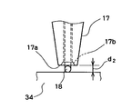
- the initial ball 18 When the diameter of the initial ball 18 becomes d 2 smaller than the predetermined diameter d 1 , the initial ball 18 cannot absorb the energy of the impact load due to deformation, so that the load sensor 31 has the predetermined diameter of the initial ball 18. detecting a large impact load than in the case of d 1. As described above, when the impact load detected by the load sensor 31 is larger than a predetermined value, abnormal ball collapse or the like has occurred.
- the load sensor 31 is attached at a position where it is not deformed by the impact load.
- the load sensor 31 is attached to the highly rigid cuboid bonding arm 21 with an offset larger than the width of the flange 14 in the Z direction from the central axis 15 of the ultrasonic horn 12. Can be detected.
- the bonding pass / fail judgment device 50 compares the impact load stored in another memory with a predetermined threshold stored in another memory, and if the impact load stored in another memory is larger than the predetermined threshold, It is determined that a bonding failure such as an abnormal collapse of the ball or chip breakage has occurred, and a lamp indicating the occurrence of the bonding failure is turned on, for example. Further, the bonding quality determination device 50 may output a bonding failure occurrence signal to the control unit 60, stop the wire bonding device 10, and turn on the abnormality occurrence lamp.
- the bonding quality determination device 50 allows a signal in a frequency band lower than the resonance frequency f 0 of the ultrasonic transducer 13 to pass therethrough and the resonance frequency f 1 unique to the ultrasonic horn 12.
- An ultrasonic transducer that includes a low-pass filter 51 having a notch function that cuts off a signal in the frequency band of FIG. 1 and does not include a signal in the frequency band of the resonance frequency f 1 unique to the ultrasonic horn 12 from the signal detected by the load sensor 31.
- a signal having a frequency band lower than the resonance frequency f 0 of 13 may be extracted, the extracted signal may be stored in a memory, and the maximum value may be detected as the impact load F 0 ′.
- the periodic fluctuation load due to the high frequency component and the resonance frequency f 1 specific to the ultrasonic horn 12 is removed from the load signal detected by the load sensor 31, so that the memory is simple. Curve data is stored. Therefore, the maximum value F 0 ′ that is an impact load can be easily determined. Also, for example, a load signal from the load sensor 31 is detected at a constant cycle time, a signal is extracted through the low-pass filter 51, and only extracted data for a predetermined number of cycles is stored in a memory, and the value of the extracted data The impact load can be detected more quickly by detecting the value of the extracted signal when the increase amount of the change from positive to negative is the maximum value.
- the bonding quality determination device 50 of the present embodiment has an effect that it is possible to determine and detect a bonding failure during bonding. Further, since a bonding failure can be determined and detected during bonding, the wire bonding apparatus 10 can be stopped immediately after the bonding failure occurs, and the product in which the bonding failure has occurred can be easily repaired. There is an effect that can be done. Furthermore, since the production of a product in which bonding failure occurs during the bonding can be stopped, the yield of the product can be improved.
- the bonding failure has been described as an abnormal collapse of the ball, but it can also be applied to the determination of bonding failure caused by the destruction of a semiconductor chip or the like.
- this embodiment demonstrated the wire bonding apparatus 10, this invention is applicable also to other bonding apparatuses, such as a bump bonder.
- the wire bonding apparatus 10 of the present embodiment has the same configuration as the wire bonding apparatus 10 described with reference to FIGS. 1 to 3, and the load sensor 31 is connected via a load sensor interface 55.
- the control unit 60 Connected to the control unit 60, the control unit 60 is configured so that a signal from the load sensor 31 can be acquired.
- the load sensor interface 55 includes an A / D converter, and outputs an analog signal from the load sensor 31 to the control unit 60 as a digital signal.
- the control unit 60 acquires a signal from the load sensor 31 from the load sensor interface 55 when the wire bonding apparatus 10 starts a bonding operation. Then, as shown in step S102 of FIG. 8, the control unit 60 filters the digital signal of the load sensor 31 acquired through the load sensor interface 55 using, for example, a digital filter such as an IIR filter or an FIR filter. (Filter means), as shown in step S103 of FIG.
- a digital filter such as an IIR filter or an FIR filter.
- the digital low-pass filter extracts a load signal in a frequency band lower than the resonance frequency f 0 of the ultrasonic transducer 13 that does not include a signal in the frequency band of the resonance frequency f 1 unique to the ultrasonic horn 12.
- a signal in a frequency band lower than the resonance frequency f 0 of the ultrasonic transducer 13 and a signal in the resonance frequency f 1 unique to the ultrasonic horn 12 are allowed to pass. It is good also as a low-pass filter provided with the notch function which interrupts
- the memo of the control unit 60 stores a relatively simple curve as shown in FIG.
- the control unit 60 detects the impact load by picking up the maximum value from the filtered extracted data stored in the memory. At this time, the control unit 60 stores only the extracted data for a predetermined number of cycles in the memory, and picks up the value of the extracted data when the amount of increase in the value of the extracted data changes from positive to negative as the maximum value.
- the impact load may be detected by doing so.
- the control unit 60 compares the detected impact load with a predetermined threshold, and when the impact load is larger than the predetermined threshold, as shown in step S106 of FIG. Then, it is determined that a bonding failure has occurred, and the wire bonding apparatus 10 is stopped as shown in step S107 of FIG. Further, when the impact load is equal to or less than the predetermined threshold, the control unit 60 determines that the bonding is good as shown in step S108 in FIG. 8 (determination means).
- the wire bonding apparatus 10 can determine and detect a bonding failure during bonding, and can stop the wire bonding apparatus 10 immediately after the bonding failure occurs. There is an effect that it is possible to easily repair a defective product. Furthermore, since the production of a product in which bonding failure occurs during the bonding can be stopped, the yield of the product can be improved.
- the wire bonding apparatus 10 has been described, but the present invention can also be applied to other bonding apparatuses such as a bump bonder.
Landscapes
- Engineering & Computer Science (AREA)
- Mechanical Engineering (AREA)
- Quality & Reliability (AREA)
- Wire Bonding (AREA)
- Pressure Welding/Diffusion-Bonding (AREA)
- Electric Connection Of Electric Components To Printed Circuits (AREA)
Priority Applications (2)
| Application Number | Priority Date | Filing Date | Title |
|---|---|---|---|
| CN2008801304172A CN102099903B (zh) | 2008-07-16 | 2008-12-16 | 焊接好坏判定方法,焊接好坏判定装置以及焊接装置 |
| US13/005,746 US8181527B2 (en) | 2008-07-16 | 2011-01-13 | Method and apparatus for pass/fail determination of bonding and bonding apparatus |
Applications Claiming Priority (2)
| Application Number | Priority Date | Filing Date | Title |
|---|---|---|---|
| JP2008184386A JP4275724B1 (ja) | 2008-07-16 | 2008-07-16 | ボンディング良否判定方法およびボンディング良否判定装置ならびにボンディング装置 |
| JP2008-184386 | 2008-07-16 |
Related Child Applications (1)
| Application Number | Title | Priority Date | Filing Date |
|---|---|---|---|
| US13/005,746 Continuation US8181527B2 (en) | 2008-07-16 | 2011-01-13 | Method and apparatus for pass/fail determination of bonding and bonding apparatus |
Publications (1)
| Publication Number | Publication Date |
|---|---|
| WO2010007702A1 true WO2010007702A1 (ja) | 2010-01-21 |
Family
ID=40821547
Family Applications (1)
| Application Number | Title | Priority Date | Filing Date |
|---|---|---|---|
| PCT/JP2008/072814 Ceased WO2010007702A1 (ja) | 2008-07-16 | 2008-12-16 | ボンディング良否判定方法およびボンディング良否判定装置ならびにボンディング装置 |
Country Status (6)
| Country | Link |
|---|---|
| US (1) | US8181527B2 (https=) |
| JP (1) | JP4275724B1 (https=) |
| KR (1) | KR101035239B1 (https=) |
| CN (1) | CN102099903B (https=) |
| TW (1) | TW201005848A (https=) |
| WO (1) | WO2010007702A1 (https=) |
Cited By (2)
| Publication number | Priority date | Publication date | Assignee | Title |
|---|---|---|---|---|
| CN113852893A (zh) * | 2020-06-28 | 2021-12-28 | 北京小米移动软件有限公司 | 数据处理方法及装置、终端和存储介质 |
| TWI771750B (zh) * | 2019-09-19 | 2022-07-21 | 日商東芝股份有限公司 | 導線接合裝置及導線接合方法 |
Families Citing this family (22)
| Publication number | Priority date | Publication date | Assignee | Title |
|---|---|---|---|---|
| US8899469B2 (en) * | 2013-03-04 | 2014-12-02 | Kulicke And Soffa Industries, Inc. | Automatic rework processes for non-stick conditions in wire bonding operations |
| US9981337B2 (en) * | 2014-05-13 | 2018-05-29 | Sonics & Materials, Inc. | Diagnostic system and method for testing integrity of stack during ultrasonic welding |
| JP6575161B2 (ja) * | 2015-06-16 | 2019-09-18 | 富士電機株式会社 | 良否判断装置、ワイヤボンダ装置及び良否判断方法 |
| KR102206867B1 (ko) * | 2016-09-07 | 2021-01-25 | 가부시키가이샤 신가와 | 와이어 본딩 장치 |
| JP6664300B2 (ja) * | 2016-09-21 | 2020-03-13 | 三菱電機株式会社 | ワイヤボンディング良否判定装置およびワイヤボンディング良否判定方法 |
| JP7008370B2 (ja) * | 2018-07-11 | 2022-02-14 | 株式会社新川 | ワイヤボンディング装置 |
| CN112585732B (zh) * | 2018-08-06 | 2024-10-11 | 株式会社新川 | 接合头 |
| SG11202104391RA (en) * | 2019-03-13 | 2021-05-28 | Shinkawa Kk | Wire non-attachment inspection system, wire non-attachment detection device, and wire non-attachment detection method |
| US11581285B2 (en) * | 2019-06-04 | 2023-02-14 | Kulicke And Soffa Industries, Inc. | Methods of detecting bonding between a bonding wire and a bonding location on a wire bonding machine |
| US11610860B2 (en) | 2019-09-19 | 2023-03-21 | Kabushiki Kaisha Toshiba | Wire bonding apparatus and wire bonding method |
| JP7577501B2 (ja) * | 2020-10-07 | 2024-11-05 | 株式会社東芝 | 超音波接合装置、制御装置及び制御方法 |
| JP7794821B2 (ja) | 2020-11-05 | 2026-01-06 | クリック アンド ソッファ インダストリーズ、インク. | ワイヤボンディング装置におけるボンディング力の精度を監視する方法を含む、ワイヤボンディング装置を動作させる方法、および関連する方法 |
| US11741747B2 (en) | 2021-01-13 | 2023-08-29 | Ford Global Technologies, Llc | Material spectroscopy |
| US11443527B2 (en) | 2021-01-13 | 2022-09-13 | Ford Global Technologies, Llc | Material spectroscopy |
| CN113399813B (zh) * | 2021-07-13 | 2022-05-03 | 北京半导体专用设备研究所(中国电子科技集团公司第四十五研究所) | 适用于压焊机的超声波换能装置 |
| US11691214B2 (en) * | 2021-10-17 | 2023-07-04 | Shinkawa Ltd. | Ultrasound horn |
| CN118743004A (zh) * | 2022-03-25 | 2024-10-01 | 株式会社新川 | 半导体装置制造装置及检查方法 |
| CN115219416B (zh) * | 2022-07-19 | 2025-07-04 | 吉林冠腾自动化技术有限公司 | 一种运载工具粘接结构健康状态离线检测装置及其检测方法 |
| CN117637510B (zh) * | 2023-11-29 | 2024-10-29 | 重庆理工大学 | 一种半导体检测装置 |
| JP2025122515A (ja) * | 2024-02-08 | 2025-08-21 | 株式会社東芝 | ワイヤボンディング装置、制御装置、及び制御方法 |
| CN118706966A (zh) * | 2024-08-02 | 2024-09-27 | 广州佑田精密电机有限公司 | 一种电机的虚焊检测系统及其检测方法 |
| CN121650265A (zh) * | 2026-02-06 | 2026-03-13 | 余姚泰速自动化科技有限公司 | 一种汽车保险杠的配合焊接方法及系统 |
Citations (2)
| Publication number | Priority date | Publication date | Assignee | Title |
|---|---|---|---|---|
| JP2002118136A (ja) * | 2000-10-12 | 2002-04-19 | Matsushita Electric Ind Co Ltd | バンプボンディング装置 |
| JP2008021839A (ja) * | 2006-07-13 | 2008-01-31 | Shinkawa Ltd | ワイヤボンディング装置 |
Family Cites Families (2)
| Publication number | Priority date | Publication date | Assignee | Title |
|---|---|---|---|---|
| JP2752890B2 (ja) | 1993-09-03 | 1998-05-18 | 日本電気株式会社 | ワイヤボンディング装置 |
| JP3818932B2 (ja) | 2002-03-04 | 2006-09-06 | 株式会社カイジョー | ワイヤボンディング装置 |
-
2008
- 2008-07-16 JP JP2008184386A patent/JP4275724B1/ja active Active
- 2008-11-19 TW TW97144642A patent/TW201005848A/zh unknown
- 2008-12-16 KR KR1020107027140A patent/KR101035239B1/ko active Active
- 2008-12-16 WO PCT/JP2008/072814 patent/WO2010007702A1/ja not_active Ceased
- 2008-12-16 CN CN2008801304172A patent/CN102099903B/zh active Active
-
2011
- 2011-01-13 US US13/005,746 patent/US8181527B2/en active Active
Patent Citations (2)
| Publication number | Priority date | Publication date | Assignee | Title |
|---|---|---|---|---|
| JP2002118136A (ja) * | 2000-10-12 | 2002-04-19 | Matsushita Electric Ind Co Ltd | バンプボンディング装置 |
| JP2008021839A (ja) * | 2006-07-13 | 2008-01-31 | Shinkawa Ltd | ワイヤボンディング装置 |
Cited By (2)
| Publication number | Priority date | Publication date | Assignee | Title |
|---|---|---|---|---|
| TWI771750B (zh) * | 2019-09-19 | 2022-07-21 | 日商東芝股份有限公司 | 導線接合裝置及導線接合方法 |
| CN113852893A (zh) * | 2020-06-28 | 2021-12-28 | 北京小米移动软件有限公司 | 数据处理方法及装置、终端和存储介质 |
Also Published As
| Publication number | Publication date |
|---|---|
| JP2010027699A (ja) | 2010-02-04 |
| US8181527B2 (en) | 2012-05-22 |
| US20110146408A1 (en) | 2011-06-23 |
| JP4275724B1 (ja) | 2009-06-10 |
| CN102099903B (zh) | 2013-05-01 |
| CN102099903A (zh) | 2011-06-15 |
| TW201005848A (en) | 2010-02-01 |
| TWI373816B (https=) | 2012-10-01 |
| KR101035239B1 (ko) | 2011-05-18 |
| KR20100135974A (ko) | 2010-12-27 |
Similar Documents
| Publication | Publication Date | Title |
|---|---|---|
| JP4275724B1 (ja) | ボンディング良否判定方法およびボンディング良否判定装置ならびにボンディング装置 | |
| JP4314313B1 (ja) | ボンディング装置 | |
| US11302667B2 (en) | Method of vertically vibrating a bonding arm | |
| JP4546576B2 (ja) | バンプ接合判定装置及び方法、並びに半導体部品製造装置及び方法 | |
| WO2018110417A1 (ja) | ワイヤボンディング装置及びワイヤボンディング方法 | |
| US8123108B2 (en) | Method of manufacturing semiconductor device and wire bonding apparatus | |
| US8231046B2 (en) | Wire bonding apparatus and wire bonding method | |
| US6962281B2 (en) | Bonding apparatus and bonding method having process for judging bonding state | |
| KR101548949B1 (ko) | 초음파 본딩 타입 메탈 와이어 본딩 장치 | |
| JP4595020B2 (ja) | ボンディング装置及びボンディングツール振巾測定方法ならびにボンディングツール振巾較正方法 | |
| JP2708222B2 (ja) | ボンディング装置 | |
| JP4239881B2 (ja) | 電子部品装着装置および電子部品装着方法 | |
| JP2017216314A (ja) | ボンディング装置、ボンディング方法及びプログラム | |
| KR101411937B1 (ko) | 실시간 메탈 와이어 본딩 품질 검사 방법 | |
| JP2000174056A (ja) | ワイヤボンディング装置 | |
| KR102536694B1 (ko) | 와이어 본딩 장치 및 와이어 본딩 방법 | |
| JP2025122515A (ja) | ワイヤボンディング装置、制御装置、及び制御方法 | |
| JP3912361B2 (ja) | ワイヤボンディング装置 | |
| JPH08203955A (ja) | ボンディング装置 |
Legal Events
| Date | Code | Title | Description |
|---|---|---|---|
| WWE | Wipo information: entry into national phase |
Ref document number: 200880130417.2 Country of ref document: CN |
|
| 121 | Ep: the epo has been informed by wipo that ep was designated in this application |
Ref document number: 08876581 Country of ref document: EP Kind code of ref document: A1 |
|
| ENP | Entry into the national phase |
Ref document number: 20107027140 Country of ref document: KR Kind code of ref document: A |
|
| NENP | Non-entry into the national phase |
Ref country code: DE |
|
| 122 | Ep: pct application non-entry in european phase |
Ref document number: 08876581 Country of ref document: EP Kind code of ref document: A1 |