US8181527B2 - Method and apparatus for pass/fail determination of bonding and bonding apparatus - Google Patents
Method and apparatus for pass/fail determination of bonding and bonding apparatus Download PDFInfo
- Publication number
- US8181527B2 US8181527B2 US13/005,746 US201113005746A US8181527B2 US 8181527 B2 US8181527 B2 US 8181527B2 US 201113005746 A US201113005746 A US 201113005746A US 8181527 B2 US8181527 B2 US 8181527B2
- Authority
- US
- United States
- Prior art keywords
- bonding
- signal
- ultrasonic horn
- load
- pass
- Prior art date
- Legal status (The legal status is an assumption and is not a legal conclusion. Google has not performed a legal analysis and makes no representation as to the accuracy of the status listed.)
- Active
Links
Images




Classifications
-
- B—PERFORMING OPERATIONS; TRANSPORTING
- B23—MACHINE TOOLS; METAL-WORKING NOT OTHERWISE PROVIDED FOR
- B23K—SOLDERING OR UNSOLDERING; WELDING; CLADDING OR PLATING BY SOLDERING OR WELDING; CUTTING BY APPLYING HEAT LOCALLY, e.g. FLAME CUTTING; WORKING BY LASER BEAM
- B23K20/00—Non-electric welding by applying impact or other pressure, with or without the application of heat, e.g. cladding or plating
- B23K20/002—Non-electric welding by applying impact or other pressure, with or without the application of heat, e.g. cladding or plating specially adapted for particular articles or work
- B23K20/004—Wire welding
- B23K20/005—Capillary welding
- B23K20/007—Ball bonding
-
- B—PERFORMING OPERATIONS; TRANSPORTING
- B23—MACHINE TOOLS; METAL-WORKING NOT OTHERWISE PROVIDED FOR
- B23K—SOLDERING OR UNSOLDERING; WELDING; CLADDING OR PLATING BY SOLDERING OR WELDING; CUTTING BY APPLYING HEAT LOCALLY, e.g. FLAME CUTTING; WORKING BY LASER BEAM
- B23K31/00—Processes relevant to this subclass, specially adapted for particular articles or purposes, but not covered by any single one of main groups B23K1/00 - B23K28/00
- B23K31/12—Processes relevant to this subclass, specially adapted for particular articles or purposes, but not covered by any single one of main groups B23K1/00 - B23K28/00 relating to investigating the properties, e.g. the weldability, of materials
- B23K31/125—Weld quality monitoring
-
- B—PERFORMING OPERATIONS; TRANSPORTING
- B23—MACHINE TOOLS; METAL-WORKING NOT OTHERWISE PROVIDED FOR
- B23K—SOLDERING OR UNSOLDERING; WELDING; CLADDING OR PLATING BY SOLDERING OR WELDING; CUTTING BY APPLYING HEAT LOCALLY, e.g. FLAME CUTTING; WORKING BY LASER BEAM
- B23K2101/00—Articles made by soldering, welding or cutting
- B23K2101/36—Electric or electronic devices
- B23K2101/42—Printed circuits
-
- H—ELECTRICITY
- H10—SEMICONDUCTOR DEVICES; ELECTRIC SOLID-STATE DEVICES NOT OTHERWISE PROVIDED FOR
- H10W—GENERIC PACKAGES, INTERCONNECTIONS, CONNECTORS OR OTHER CONSTRUCTIONAL DETAILS OF DEVICES COVERED BY CLASS H10
- H10W72/00—Interconnections or connectors in packages
- H10W72/071—Connecting or disconnecting
- H10W72/0711—Apparatus therefor
- H10W72/07141—Means for applying energy, e.g. ovens or lasers
-
- H—ELECTRICITY
- H10—SEMICONDUCTOR DEVICES; ELECTRIC SOLID-STATE DEVICES NOT OTHERWISE PROVIDED FOR
- H10W—GENERIC PACKAGES, INTERCONNECTIONS, CONNECTORS OR OTHER CONSTRUCTIONAL DETAILS OF DEVICES COVERED BY CLASS H10
- H10W72/00—Interconnections or connectors in packages
- H10W72/071—Connecting or disconnecting
- H10W72/0711—Apparatus therefor
- H10W72/07183—Means for monitoring
-
- H—ELECTRICITY
- H10—SEMICONDUCTOR DEVICES; ELECTRIC SOLID-STATE DEVICES NOT OTHERWISE PROVIDED FOR
- H10W—GENERIC PACKAGES, INTERCONNECTIONS, CONNECTORS OR OTHER CONSTRUCTIONAL DETAILS OF DEVICES COVERED BY CLASS H10
- H10W72/00—Interconnections or connectors in packages
- H10W72/071—Connecting or disconnecting
- H10W72/075—Connecting or disconnecting of bond wires
- H10W72/07531—Techniques
- H10W72/07532—Compression bonding, e.g. thermocompression bonding
- H10W72/07533—Ultrasonic bonding, e.g. thermosonic bonding
-
- H—ELECTRICITY
- H10—SEMICONDUCTOR DEVICES; ELECTRIC SOLID-STATE DEVICES NOT OTHERWISE PROVIDED FOR
- H10W—GENERIC PACKAGES, INTERCONNECTIONS, CONNECTORS OR OTHER CONSTRUCTIONAL DETAILS OF DEVICES COVERED BY CLASS H10
- H10W72/00—Interconnections or connectors in packages
- H10W72/50—Bond wires
- H10W72/551—Materials of bond wires
- H10W72/552—Materials of bond wires comprising metals or metalloids, e.g. silver
Definitions
- the present invention relates to a method and apparatus for pass/fail determination of bonding for use in bonding apparatuses and to a structure of a bonding apparatus for pass/fail determination of bonding.
- wire-bonding apparatuses are often used for bonding of thin metallic wires to electrode pads on a semiconductor chip and electrode leads on a lead frame for connection therebetween.
- Many wire-bonding apparatuses include a bonding arm configured to be rotated with a drive motor, an ultrasonic horn attached to the bonding arm, a capillary attached at one end of the ultrasonic horn, and an ultrasonic vibrator attached to the ultrasonic horn.
- the bonding arm is driven and rotated to move the capillary in a direction toward and away from a pad or lead and to press and bond an initial ball formed at a tip end of the capillary or a wire to the pad or lead, and then the ultrasonic horn is resonated by the ultrasonic vibrator to provide ultrasonic vibration at the tip end of the capillary for bonding operation.
- an initial ball formed at a tip end of a wire that is inserted through the capillary collides with a pad at a certain speed and then is pressed and bonded at a constant load to the pad to be a bonded ball.
- the collision causes the wire and capillary to vibrate in the pressing direction also during the subsequent period of pressing at the constant load, and thereby the pressing load to fluctuate and the shape and diameter of the bonded ball to vary, which can result in defective bonding.
- the pressing load can fluctuate to result in defective bonding.
- wire-bonding apparatuses generally include an encoder provided in a bonding head to detect the change in the height position of the capillary, in which a detection output of the encoder is fed back to a controller to control the output of the drive motor and thereby to prevent the pressing load from fluctuating.
- a detection output of the encoder is fed back to a controller to control the output of the drive motor and thereby to prevent the pressing load from fluctuating.
- the encoder cannot detect the pressing load on the wire directly, the fluctuation of the pressing load cannot be suppressed sufficiently only by feed-backing the output of the encoder.
- the present invention is directed to a method of pass/fail determination of bonding, including: preparing a bonding apparatus including: a base unit; an ultrasonic horn configured to vibrate longitudinally in resonance with the vibration of an ultrasonic vibrator; a bonding tool attached at an anti-node of the vibration of the ultrasonic horn; a flange provided at a node of the vibration of the ultrasonic horn; a bonding arm including a flange mounting surface, the flange being fixed to the ultrasonic horn, and attached rotatably to the base unit in such a manner as to move a tip end of the bonding tool in a direction toward and away from a bonding target; and a load sensor attached between the center of rotation of the bonding arm and the flange mounting surface in an offset manner in the direction toward and away from the bonding target from a longitudinal central axis of the ultrasonic horn; continuously detecting a load on the bonding tool in the direction toward and away from the bonding target using the
- the method of pass/fail determination of bonding according to the present invention can preferably be arranged such that if the impact load is larger than a predetermined threshold value, the bonding is determined to be defective.
- the method can preferably be arranged to include: extracting a signal within a frequency range lower than the resonant frequency of the ultrasonic vibrator, except for a signal within a frequency range of the natural resonance frequency to the ultrasonic horn, from a load signal detected with the load sensor through a filter that a signal within the frequency range of the natural resonance frequency to the ultrasonic horn is cut off and that is able to pass the signal within the frequency range lower than the resonant frequency of the ultrasonic vibrator; and determining pass/fail of the bonding based on the extracted signal.
- the method can preferably be further arranged such that after the grounding of the bonding tool, if the rate of increase in the load signal detected with the load sensor to time is greater than a threshold value, it is determined that there is abnormal ball deformation
- the present invention is also directed to an apparatus for pass/fail determination of bonding used in a bonding apparatus, the apparatus including: a base unit; an ultrasonic horn configured to vibrate longitudinally in resonance with the vibration of an ultrasonic vibrator; a bonding tool attached at an anti-node of the vibration of the ultrasonic horn; a flange provided at a node of the vibration of the ultrasonic horn; a bonding arm including a flange mounting surface, the flange being fixed to the ultrasonic horn and attached rotatably to the base unit in such a manner as to move a tip end of the bonding tool in a direction toward and away from a bonding target; and a load sensor attached between the center of rotation of the bonding arm and the flange mounting surface in an offset manner in the direction toward and away from the bonding target from a longitudinal central axis of the ultrasonic horn, in which the apparatus is extracting a signal within a frequency range lower than the resonant frequency of the
- the present invention is further directed to a bonding apparatus including: a base unit; a base unit; an ultrasonic horn configured to vibrate longitudinally in resonance with the vibration of an ultrasonic vibrator; a bonding tool attached at an anti-node of the vibration of the ultrasonic horn; a flange provided at a node of the vibration of the ultrasonic horn; a bonding arm including a flange mounting surface, the flange being fixed to the ultrasonic horn and attached rotatably to the base unit in such a manner as to move a tip end of the bonding tool in a direction toward and away from a bonding target; a load sensor attached between the center of rotation of the bonding arm and the flange mounting surface in an offset manner in the direction toward and away from the bonding target from a longitudinal central axis of the ultrasonic horn; a control unit for pass/fail determination of bonding; the control unit including: filter means for cutting off a signal within the frequency range of the natural resonance frequency to
- the present invention is advantageous in that it is possible to make a mid-bonding pass/fail determination.
- FIG. 1 illustrates a wire-bonding apparatus to which a bonding pass/fail determination apparatus according to an exemplary embodiment of the present invention is applied;
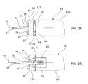
- FIG. 2A is a top plan view of a bonding arm in the wire-bonding apparatus to which the bonding pass/fail determination apparatus according to an exemplary embodiment of the present invention is applied;
- FIG. 2B is a bottom plan view of a bonding arm in the wire-bonding apparatus to which the bonding pass/fail determination apparatus according to an exemplary embodiment of the present invention is applied;
- FIG. 3 is a schematic view illustrating ultrasonic vibration in the wire-bonding apparatus to which the bonding pass/fail determination apparatus according to an exemplary embodiment of the present invention is applied;
- FIG. 4 illustrates signal processing at the bonding pass/fail determination apparatus according to an exemplary embodiment of the present invention
- FIG. 5A illustrates a change in the state of an initial ball during bonding operation in the wire-bonding apparatus to which the bonding pass/fail determination apparatus according to an exemplary embodiment of the present invention is applied;
- FIG. 5B illustrates a further change in the state of the initial ball during bonding operation in the wire-bonding apparatus to which the bonding pass/fail determination apparatus according to an exemplary embodiment of the present invention is applied;
- FIG. 5C also illustrates a change in the state of an initial ball during bonding operation in the wire-bonding apparatus to which the bonding pass/fail determination apparatus according to an exemplary embodiment of the present invention is applied;
- FIG. 5D illustrates a further change in the state of the initial ball during bonding operation in the wire-bonding apparatus to which the bonding pass/fail determination apparatus according to an exemplary embodiment of the present invention is applied;
- FIG. 6 is a graph illustrating how pressing load changes in time after filtering in the bonding pass/fail determination apparatus according to an exemplary embodiment of the present invention
- FIG. 7 illustrates a wire-bonding apparatus according to another exemplary embodiment of the present invention.
- FIG. 8 is a flow chart illustrating an operation of the wire-bonding apparatus according to an exemplary embodiment of the present invention.
- a wire-bonding apparatus 10 in which a bonding pass/fail determination apparatus 50 according to an exemplary embodiment is installed includes a bonding head 11 serving as a base unit, an ultrasonic vibrator 13 , an ultrasonic horn 12 , a capillary 17 serving as a bonding tool, a flange 14 provided on the ultrasonic horn 12 , a bonding arm 21 , a load sensor 31 , a drive motor 45 , a control unit 60 , and a bonding stage 33 on which a semiconductor chip 34 or a substrate 35 is absorbed and fixed as a bonding target.
- the drive motor 45 for rotating the bonding arm 21 is provided on the bonding head 11 .
- the ultrasonic vibrator 13 is formed by overlaying multiple piezoelectric elements and attached at the rear end of the ultrasonic horn 12 .
- the capillary 17 is attached at one end of the ultrasonic horn 12 .
- the flange 14 is provided at a node of the vibration of the ultrasonic horn 12 to be described hereinafter and fixed using a bolt 16 to a flange mounting surface 22 at one end of the bonding arm 21 .
- the bonding arm 21 is attached rotatably about a rotation axis 30 provided on the bonding head 11 .
- the center of rotation 43 of the bonding arm 21 is coplanar with the surface of the substrate 35 absorbed on the bonding stage 33 or the surface of the semiconductor chip 34 mounted on the substrate 35 .
- the bonding arm 21 has an approximately rectangular parallelepiped shape extending in a direction along the central axis 15 of the ultrasonic horn 12 , and has a front end portion 21 a including the flange mounting surface 22 and a rear end portion 21 b including the center of rotation 43 .
- the front and rear end portions 21 a and 21 b are connected via a thin plate-like connection 24 provided at a height position (in the Z direction) including the central axis 15 of the ultrasonic horn 12 .
- narrow slits 23 and 25 are formed, respectively, on the side of the bonding surface 41 and its opposite side with respect to the connection 24 .
- a groove 26 for fitting the load sensor 31 therein.
- the groove 26 is provided in an opposed manner between the front and rear end portions 21 a and 21 b of the bonding arm 21 .
- the load sensor 31 fitted in the groove 26 is sandwiched in between the front and rear end portions 21 a and 21 b of the bonding arm 21 and pressurized using screws 27 inserted through the front end portion 21 a into the rear end portion 21 b .
- the central axis 28 of the load sensor 31 is offset from the central axis 15 of the ultrasonic horn 12 by a distance of L in the Z direction, a direction in which the tip end 17 a of the capillary 17 moves toward and away from the bonding surface 41 .
- the distance L is greater than the Z-directional width of the flange 14 to have high rigidity against a bending force applied from the capillary 17 onto the ultrasonic horn 12 .
- the load sensor 31 is mounted at the center in the width direction of the bonding arm 21 , and the screws 27 are provided on either side of the load sensor 31 .
- a recess 29 for housing the ultrasonic horn 12 and ultrasonic vibrator 13 therein is provided on the side of the bonding surface 41 in the bonding arm 21 .
- the ultrasonic horn 12 is configured to vibrate in a longitudinal direction along the central axis 15 in resonance with the ultrasonic vibrator 13 .
- Longitudinal vibration here means that the direction of propagation of the vibration and the direction of its amplitude are identical.
- the vibration of the ultrasonic vibrator 13 that is attached to the rear end of the ultrasonic horn 12 causes the ultrasonic horn 12 to vibrate between the rear end at which the ultrasonic vibrator 13 is attached and the front end at which the capillary 17 is attached in a resonant mode in which anti-nodes of the vibration are formed at the rear and front ends.
- the flange 14 is then provided at a node of the vibration between the rear and front ends, that is, a site that does not vibrate even in a resonant state to fix the ultrasonic horn 12 to the bonding arm 21 .
- the flange 14 is fixed by using the bolt 16 to the flange mounting surface 22 on the bonding arm 21 . Since the flange 14 does not vibrate with the resonance of the ultrasonic horn 12 , ultrasonic vibration due to the resonance of the ultrasonic horn 12 cannot propagate to the flange mounting surface 22 on the bonding arm 21 . Therefore, the ultrasonic vibration due to the resonance of the ultrasonic horn 12 cannot also propagate to the load sensor 31 provided on the bonding arm 21 . It is noted that FIG.
- FIG. 3 is a schematic view illustrating the relationship among the bonding arm 21 , ultrasonic horn 12 , flange 14 , and bolt 16 , where the flange 14 , which extends horizontally in the XY direction from the ultrasonic horn 12 , is drawn vertically. Also, FIG. 3 ( b ) schematically illustrates the amplitude of the ultrasonic horn 12 , where the amplitude in the direction along the central axis 15 is drawn as orthogonal to the central axis 15 .
- the bonding pass/fail determination apparatus 50 is connected with the load sensor 31 and includes a low-pass filter.
- the low-pass filter has a notch feature by which a signal within a frequency range lower than the frequency of resonance f 0 of the ultrasonic vibrator 13 passes and a signal within a frequency range of the frequency of resonance f 1 specific to the ultrasonic horn 12 is cut off. It is therefore possible to extract from a signal detected by the load sensor 31 a signal within the frequency range lower than the frequency of resonance f 0 of the ultrasonic vibrator 13 not including a signal within the frequency range of the frequency of resonance f 1 specific to the ultrasonic horn 12 .
- the ultrasonic vibrator 13 and the drive motor 45 are connected to the control unit 60 , whereby the control unit 60 can control the output of the ultrasonic vibrator 13 and the direction of rotation as well as output of the drive motor 45 .
- the bonding pass/fail determination apparatus 50 is also connected to the control unit 60 , whereby the control unit 60 can receive a signal of pass/fail determination of bonding.
- the bonding pass/fail determination apparatus 50 and the control unit 60 can be configured as a computer including a CPU, memory, etc.
- the detection and control systems can be configured by an electric circuit.
- the control unit 60 shown in FIG. 1 forms a tip end of a wire extending out of the tip end 17 a of the capillary 17 into a spherical initial ball 18 using such as a discharge torch (not shown).
- the control unit 60 then issues a command to drive the drive motor 45 . Receiving this command, the drive motor 45 starts to rotate and lower the capillary 17 onto the semiconductor chip 34 .
- the control unit 60 also issues a command to start the vibration of the ultrasonic vibrator 13 . Receiving this command, the ultrasonic vibrator 13 is applied by a voltage for a vibration output preset correspondingly to bonding conditions.
- the bonding pass/fail determination apparatus 50 starts to store a load signal from the load sensor 31 into a memory.
- the ultrasonic horn 12 is in resonance with the vibration of the ultrasonic vibrator 13 and vibrates longitudinally with anti-nodes of the vibration being formed at the front end where the capillary 17 is attached and the rear end where the ultrasonic vibrator 13 is attached, as shown in FIG. 3 .
- the flange 14 which is arranged at a node of the vibration, does not vibrate with the resonance of the ultrasonic horn 12 and thus the load sensor 31 detects no load.
- the ultrasonic horn 12 undergoes a small vibration in the Z direction at the specific frequency of resonance f 1 due to a collision with a pad during bonding operation. Therefore, the load sensor 31 detects a small periodically fluctuating load due to the vibration of the ultrasonic horn 12 as shown in FIG. 4 ( a ).
- the bonding arm 21 is accelerated with the drive motor 45 and collides with a pad on the semiconductor chip 34 at a predetermined lowering speed at time t 1 in FIG. 4 ( a ). This causes the pressing load detected with the load sensor 31 to increase rapidly to reach a maximum value of F 1 at time t 2 in FIG. 4 ( a ).
- the control unit 60 controls the drive motor 45 to make the pressing load detected with the load sensor 31 equal to a predetermined pressing load P 0 . After a predetermined pressing time has passed, the control unit 60 then drives the drive motor 45 in the opposite direction of the initial drive to raise the capillary 17 .
- the bonding pass/fail determination apparatus 50 stores load signals from the load sensor 31 into the memory, and then stores the maximum value F 1 into another memory as an impact load.
- the impact load due to the lowering of the capillary 17 deforms the initial ball 18 into a disk-like bonded ball 19 having a predetermined thickness of H 1 as shown in FIG. 5B .
- the initial ball 18 has a diameter of d 2 smaller than a predetermined value as shown in FIG. 5C , the initial ball 18 , when deformed with the tip end 17 a of the capillary 17 , gets into an inner chamfer 17 b formed at the tip end of the capillary 17 , so that the bonded ball 19 has a thickness of H 2 smaller than the predetermined thickness H 1 as shown in FIG.
- the load sensor 31 detects a larger impact load than if the initial ball 18 has the predetermined diameter d 1 because the energy of the impact load cannot be absorbed by the deformation of the initial ball 18 .
- the impact load detected with the load sensor 31 is thus larger than a predetermined value, it is determined that there occurs abnormal ball deformation or the like.
- the load sensor 31 In order to detect the impact load accurately, it is also necessary for the load sensor 31 to be attached at a site not to be deformed by the impact load.
- the load sensor 31 is attached to the rigid rectangular parallelepiped bonding arm 21 with an offset from the central axis 15 of the ultrasonic horn 12 greater than the Z-directional width of the flange 14 , whereby the load sensor 31 can detect accurately the impact load.
- the bonding pass/fail determination apparatus 50 compares the impact load stored in the another memory with a predetermined threshold value stored in still another memory and, if the impact load stored in the another memory is larger than the predetermined threshold value, determines that there occurs defective bonding such as abnormal ball deformation or chip damage, and then, for example, turns on a lamp that indicates the occurrence of defective bonding.
- the bonding pass/fail determination apparatus 50 can further output a defective bonding signal to the control unit 60 , stop the wire-bonding apparatus 10 , and turn on an abnormal operation warning lamp.
- the bonding pass/fail determination apparatus 50 can include a low-pass filter 51 having a notch feature by which a signal within a frequency range lower than the frequency of resonance f 0 of the ultrasonic vibrator 13 passes and a signal within a frequency range of the frequency of resonance f 1 specific to the ultrasonic horn 12 is cut off, extract from a signal detected by the load sensor 31 a signal within the frequency range lower than the frequency of resonance f 0 of the ultrasonic vibrator 13 not including a signal within the frequency range of the frequency of resonance f 1 specific to the ultrasonic horn 12 , and store the extracted signal into the memory to detect the maximum value as an impact load F 0 ′.
- the impact load increases and the gradient of increase in the signal extracted through the filter 51 indicated with the alternate long and short dash line “b” in FIG. 6 is greater than the gradient of increase in the signal extracted during normal bonding operation indicated with the solid line “a” in FIG. 6 . It can therefore be determined that there occurs defective bonding such as abnormal ball deformation if the rate of increase in the extracted signal to time is greater than a threshold value.
- the bonding pass/fail determination apparatus 50 offers the advantage of making a mid-bonding pass/fail determination and detection.
- This advantage of making a mid-bonding pass/fail determination and detection also allows the wire-bonding apparatus 10 to be stopped immediately after defective bonding, if occurred, offering the advantage that the product with the defective bonding can be revised easily. Further, the production of the product with the defective bonding can be stopped during the bonding operation, offering the advantage of improving production yield.
- the present invention can also be applied to determination of defective bonding due to damage on a semiconductor chip or the like.
- the wire-bonding apparatus 10 is exemplified in the description of the exemplary embodiment, the present invention can also be applied to other kinds of bonding apparatuses such as bump bonders.
- defective bonding is determined by the bonding pass/fail determination apparatus 50 that is provided separately from the control unit 60 .
- the wire-bonding apparatus 10 is arranged such that the control unit 60 makes a determination of defective bonding.
- Components identical to those in the exemplary embodiment described with reference to FIGS. 1 to 6 are designated with the same reference numerals to omit the description thereof.
- the wire-bonding apparatus 10 is configured similarly to the wire-bonding apparatus 10 described with reference to FIGS. 1 to 3 , except that the load sensor 31 is connected to the control unit 60 via a load sensor interface 55 so that the control unit 60 can acquire a signal from the load sensor 31 .
- the load sensor interface 55 includes an ND converter to output an analog signal from the load sensor 31 to the control unit 60 as a digital signal.
- Step S 101 of FIG. 8 the control unit 60 controls the wire-bonding apparatus 10 to start a bonding action and acquires a signal from the load sensor 31 via the load sensor interface 55 .
- Step S 102 of FIG. 8 the control unit 60 then applies a digital filter such as an IIR or FIR filter (filter means) to the digital signal acquired from the load sensor 31 via the load sensor interface 55 and, as shown in Step S 103 of FIG.
- a digital filter such as an IIR or FIR filter (filter means)
- the digital low-pass filter is only required to extract a load signal within the frequency range lower than the frequency of resonance f 0 of the ultrasonic vibrator 13 not including a signal within the frequency range of the frequency of resonance f 1 specific to the ultrasonic horn 12 , that is, can be, for example, a low-pass filter having a notch feature by which a signal within a frequency range lower than the frequency of resonance f 0 of the ultrasonic vibrator 13 passes and a signal within a frequency range of the frequency of resonance f 1 specific to the ultrasonic horn 12 is cut off.
- a relatively simple curve such as shown in FIG. 4 ( c ) is stored in the memory of the control unit 60 .
- the control unit 60 picks up the maximum value among the filtered extraction data stored in the memory to detect an impact load.
- the control unit 60 can store extraction data of only a predetermined number of cycles in the memory, and pick up the value of the extraction data when the amount of increase in the value switches from positive to negative as the maximum value to detect the impact load.
- Step S 105 of FIG. 8 the control unit 60 compares the detected impact load with a predetermined threshold value and, if the impact load is larger than the predetermined threshold value, determines that there occurs defective bonding as shown in Step S 106 of FIG. 8 , and stops the wire-bonding apparatus 10 as shown in Step S 107 of FIG. 8 . If the impact load is equal to or smaller than the predetermined threshold value, the control unit 60 determines that the bonding is successful as shown in Step S 108 of FIG. 8 (determination means).
- the wire-bonding apparatus 10 offers the advantage of making a mid-bonding pass/fail determination and detection and thus being stopped immediately after defective bonding, if occurred, and that the product with the defective bonding can be revised easily. Further, the production of the product with the defective bonding can be stopped during the bonding operation, offering the advantage of improving production yield.
- wire-bonding apparatus 10 is exemplified in the description of the exemplary embodiments, the present invention can also be applied to other kinds of bonding apparatuses such as bump bonders.
Landscapes
- Engineering & Computer Science (AREA)
- Mechanical Engineering (AREA)
- Quality & Reliability (AREA)
- Wire Bonding (AREA)
- Pressure Welding/Diffusion-Bonding (AREA)
- Electric Connection Of Electric Components To Printed Circuits (AREA)
Applications Claiming Priority (3)
| Application Number | Priority Date | Filing Date | Title |
|---|---|---|---|
| JP2008184386A JP4275724B1 (ja) | 2008-07-16 | 2008-07-16 | ボンディング良否判定方法およびボンディング良否判定装置ならびにボンディング装置 |
| JP2008-184386 | 2008-07-16 | ||
| PCT/JP2008/072814 WO2010007702A1 (ja) | 2008-07-16 | 2008-12-16 | ボンディング良否判定方法およびボンディング良否判定装置ならびにボンディング装置 |
Related Parent Applications (1)
| Application Number | Title | Priority Date | Filing Date |
|---|---|---|---|
| PCT/JP2008/072814 Continuation WO2010007702A1 (ja) | 2008-07-16 | 2008-12-16 | ボンディング良否判定方法およびボンディング良否判定装置ならびにボンディング装置 |
Publications (2)
| Publication Number | Publication Date |
|---|---|
| US20110146408A1 US20110146408A1 (en) | 2011-06-23 |
| US8181527B2 true US8181527B2 (en) | 2012-05-22 |
Family
ID=40821547
Family Applications (1)
| Application Number | Title | Priority Date | Filing Date |
|---|---|---|---|
| US13/005,746 Active US8181527B2 (en) | 2008-07-16 | 2011-01-13 | Method and apparatus for pass/fail determination of bonding and bonding apparatus |
Country Status (6)
| Country | Link |
|---|---|
| US (1) | US8181527B2 (https=) |
| JP (1) | JP4275724B1 (https=) |
| KR (1) | KR101035239B1 (https=) |
| CN (1) | CN102099903B (https=) |
| TW (1) | TW201005848A (https=) |
| WO (1) | WO2010007702A1 (https=) |
Cited By (1)
| Publication number | Priority date | Publication date | Assignee | Title |
|---|---|---|---|---|
| US11865633B2 (en) | 2020-11-05 | 2024-01-09 | Kulicke And Soffa Industries, Inc. | Methods of operating a wire bonding machine, including methods of monitoring an accuracy of bond force on a wire bonding machine, and related methods |
Families Citing this family (23)
| Publication number | Priority date | Publication date | Assignee | Title |
|---|---|---|---|---|
| US8899469B2 (en) * | 2013-03-04 | 2014-12-02 | Kulicke And Soffa Industries, Inc. | Automatic rework processes for non-stick conditions in wire bonding operations |
| US9981337B2 (en) * | 2014-05-13 | 2018-05-29 | Sonics & Materials, Inc. | Diagnostic system and method for testing integrity of stack during ultrasonic welding |
| JP6575161B2 (ja) * | 2015-06-16 | 2019-09-18 | 富士電機株式会社 | 良否判断装置、ワイヤボンダ装置及び良否判断方法 |
| KR102206867B1 (ko) * | 2016-09-07 | 2021-01-25 | 가부시키가이샤 신가와 | 와이어 본딩 장치 |
| JP6664300B2 (ja) * | 2016-09-21 | 2020-03-13 | 三菱電機株式会社 | ワイヤボンディング良否判定装置およびワイヤボンディング良否判定方法 |
| JP7008370B2 (ja) * | 2018-07-11 | 2022-02-14 | 株式会社新川 | ワイヤボンディング装置 |
| CN112585732B (zh) * | 2018-08-06 | 2024-10-11 | 株式会社新川 | 接合头 |
| SG11202104391RA (en) * | 2019-03-13 | 2021-05-28 | Shinkawa Kk | Wire non-attachment inspection system, wire non-attachment detection device, and wire non-attachment detection method |
| US11581285B2 (en) * | 2019-06-04 | 2023-02-14 | Kulicke And Soffa Industries, Inc. | Methods of detecting bonding between a bonding wire and a bonding location on a wire bonding machine |
| JP7488656B2 (ja) * | 2019-09-19 | 2024-05-22 | 株式会社東芝 | ワイヤボンディング装置及びワイヤボンディング方法 |
| US11610860B2 (en) | 2019-09-19 | 2023-03-21 | Kabushiki Kaisha Toshiba | Wire bonding apparatus and wire bonding method |
| CN113852893B (zh) * | 2020-06-28 | 2024-11-05 | 北京小米移动软件有限公司 | 数据处理方法及装置、终端和存储介质 |
| JP7577501B2 (ja) * | 2020-10-07 | 2024-11-05 | 株式会社東芝 | 超音波接合装置、制御装置及び制御方法 |
| US11741747B2 (en) | 2021-01-13 | 2023-08-29 | Ford Global Technologies, Llc | Material spectroscopy |
| US11443527B2 (en) | 2021-01-13 | 2022-09-13 | Ford Global Technologies, Llc | Material spectroscopy |
| CN113399813B (zh) * | 2021-07-13 | 2022-05-03 | 北京半导体专用设备研究所(中国电子科技集团公司第四十五研究所) | 适用于压焊机的超声波换能装置 |
| US11691214B2 (en) * | 2021-10-17 | 2023-07-04 | Shinkawa Ltd. | Ultrasound horn |
| CN118743004A (zh) * | 2022-03-25 | 2024-10-01 | 株式会社新川 | 半导体装置制造装置及检查方法 |
| CN115219416B (zh) * | 2022-07-19 | 2025-07-04 | 吉林冠腾自动化技术有限公司 | 一种运载工具粘接结构健康状态离线检测装置及其检测方法 |
| CN117637510B (zh) * | 2023-11-29 | 2024-10-29 | 重庆理工大学 | 一种半导体检测装置 |
| JP2025122515A (ja) * | 2024-02-08 | 2025-08-21 | 株式会社東芝 | ワイヤボンディング装置、制御装置、及び制御方法 |
| CN118706966A (zh) * | 2024-08-02 | 2024-09-27 | 广州佑田精密电机有限公司 | 一种电机的虚焊检测系统及其检测方法 |
| CN121650265A (zh) * | 2026-02-06 | 2026-03-13 | 余姚泰速自动化科技有限公司 | 一种汽车保险杠的配合焊接方法及系统 |
Citations (4)
| Publication number | Priority date | Publication date | Assignee | Title |
|---|---|---|---|---|
| JPH0774215A (ja) | 1993-09-03 | 1995-03-17 | Nec Corp | ワイヤボンディング装置 |
| JP2002118136A (ja) | 2000-10-12 | 2002-04-19 | Matsushita Electric Ind Co Ltd | バンプボンディング装置 |
| JP2003258021A (ja) | 2002-03-04 | 2003-09-12 | Kaijo Corp | ワイヤボンディング装置 |
| JP2008021839A (ja) | 2006-07-13 | 2008-01-31 | Shinkawa Ltd | ワイヤボンディング装置 |
-
2008
- 2008-07-16 JP JP2008184386A patent/JP4275724B1/ja active Active
- 2008-11-19 TW TW97144642A patent/TW201005848A/zh unknown
- 2008-12-16 KR KR1020107027140A patent/KR101035239B1/ko active Active
- 2008-12-16 WO PCT/JP2008/072814 patent/WO2010007702A1/ja not_active Ceased
- 2008-12-16 CN CN2008801304172A patent/CN102099903B/zh active Active
-
2011
- 2011-01-13 US US13/005,746 patent/US8181527B2/en active Active
Patent Citations (5)
| Publication number | Priority date | Publication date | Assignee | Title |
|---|---|---|---|---|
| JPH0774215A (ja) | 1993-09-03 | 1995-03-17 | Nec Corp | ワイヤボンディング装置 |
| JP2002118136A (ja) | 2000-10-12 | 2002-04-19 | Matsushita Electric Ind Co Ltd | バンプボンディング装置 |
| JP2003258021A (ja) | 2002-03-04 | 2003-09-12 | Kaijo Corp | ワイヤボンディング装置 |
| JP2008021839A (ja) | 2006-07-13 | 2008-01-31 | Shinkawa Ltd | ワイヤボンディング装置 |
| US7735707B2 (en) | 2006-07-13 | 2010-06-15 | Kabushiki Kaisha Shinkawa | Wire bonding apparatus |
Non-Patent Citations (1)
| Title |
|---|
| International Search Report dated Feb. 10, 2009, from the corresponding International Application. |
Cited By (1)
| Publication number | Priority date | Publication date | Assignee | Title |
|---|---|---|---|---|
| US11865633B2 (en) | 2020-11-05 | 2024-01-09 | Kulicke And Soffa Industries, Inc. | Methods of operating a wire bonding machine, including methods of monitoring an accuracy of bond force on a wire bonding machine, and related methods |
Also Published As
| Publication number | Publication date |
|---|---|
| JP2010027699A (ja) | 2010-02-04 |
| US20110146408A1 (en) | 2011-06-23 |
| JP4275724B1 (ja) | 2009-06-10 |
| WO2010007702A1 (ja) | 2010-01-21 |
| CN102099903B (zh) | 2013-05-01 |
| CN102099903A (zh) | 2011-06-15 |
| TW201005848A (en) | 2010-02-01 |
| TWI373816B (https=) | 2012-10-01 |
| KR101035239B1 (ko) | 2011-05-18 |
| KR20100135974A (ko) | 2010-12-27 |
Similar Documents
| Publication | Publication Date | Title |
|---|---|---|
| US8181527B2 (en) | Method and apparatus for pass/fail determination of bonding and bonding apparatus | |
| US8800843B2 (en) | Bonding apparatus | |
| JP5426000B2 (ja) | ワイヤボンディング装置及びワイヤボンディング方法 | |
| US8123108B2 (en) | Method of manufacturing semiconductor device and wire bonding apparatus | |
| US9899348B2 (en) | Wire bonding apparatus and method of manufacturing semiconductor device | |
| WO2018110417A1 (ja) | ワイヤボンディング装置及びワイヤボンディング方法 | |
| US20140131425A1 (en) | Method of detecting wire bonding failures | |
| US20190287941A1 (en) | Wire bonding method and wire bonding apparatus | |
| US8231046B2 (en) | Wire bonding apparatus and wire bonding method | |
| JPH02187286A (ja) | 自動ワイヤ接着装置 | |
| US20030218050A1 (en) | Bonding apparatus and bonding method having process for judging bonding state | |
| KR101548949B1 (ko) | 초음파 본딩 타입 메탈 와이어 본딩 장치 | |
| CN102237263A (zh) | 监测结合表面反弹的设备和方法、线结合设备及记录介质 | |
| JP2708222B2 (ja) | ボンディング装置 | |
| JP2017216314A (ja) | ボンディング装置、ボンディング方法及びプログラム | |
| JP2000174056A (ja) | ワイヤボンディング装置 | |
| KR102536694B1 (ko) | 와이어 본딩 장치 및 와이어 본딩 방법 | |
| KR101146322B1 (ko) | 와이어 본딩 기구의 진동 변위 측정방법 | |
| JPH08203955A (ja) | ボンディング装置 |
Legal Events
| Date | Code | Title | Description |
|---|---|---|---|
| AS | Assignment |
Owner name: SHINKAWA LTD., JAPAN Free format text: ASSIGNMENT OF ASSIGNORS INTEREST;ASSIGNORS:AOYAGI, NOBUYUKI;SEYAMA, KOHEI;REEL/FRAME:025902/0763 Effective date: 20110114 |
|
| FEPP | Fee payment procedure |
Free format text: PAYOR NUMBER ASSIGNED (ORIGINAL EVENT CODE: ASPN); ENTITY STATUS OF PATENT OWNER: LARGE ENTITY |
|
| STCF | Information on status: patent grant |
Free format text: PATENTED CASE |
|
| FEPP | Fee payment procedure |
Free format text: PAYOR NUMBER ASSIGNED (ORIGINAL EVENT CODE: ASPN); ENTITY STATUS OF PATENT OWNER: LARGE ENTITY Free format text: PAYER NUMBER DE-ASSIGNED (ORIGINAL EVENT CODE: RMPN); ENTITY STATUS OF PATENT OWNER: LARGE ENTITY |
|
| FPAY | Fee payment |
Year of fee payment: 4 |
|
| MAFP | Maintenance fee payment |
Free format text: PAYMENT OF MAINTENANCE FEE, 8TH YEAR, LARGE ENTITY (ORIGINAL EVENT CODE: M1552); ENTITY STATUS OF PATENT OWNER: LARGE ENTITY Year of fee payment: 8 |
|
| MAFP | Maintenance fee payment |
Free format text: PAYMENT OF MAINTENANCE FEE, 12TH YEAR, LARGE ENTITY (ORIGINAL EVENT CODE: M1553); ENTITY STATUS OF PATENT OWNER: LARGE ENTITY Year of fee payment: 12 |