WO2010005021A1 - Dispositif de lyophilisation et procédé de lyophilisation - Google Patents
Dispositif de lyophilisation et procédé de lyophilisation Download PDFInfo
- Publication number
- WO2010005021A1 WO2010005021A1 PCT/JP2009/062426 JP2009062426W WO2010005021A1 WO 2010005021 A1 WO2010005021 A1 WO 2010005021A1 JP 2009062426 W JP2009062426 W JP 2009062426W WO 2010005021 A1 WO2010005021 A1 WO 2010005021A1
- Authority
- WO
- WIPO (PCT)
- Prior art keywords
- shelf
- freeze
- raw material
- drying
- drying apparatus
- Prior art date
Links
Images


Classifications
-
- F—MECHANICAL ENGINEERING; LIGHTING; HEATING; WEAPONS; BLASTING
- F26—DRYING
- F26B—DRYING SOLID MATERIALS OR OBJECTS BY REMOVING LIQUID THEREFROM
- F26B5/00—Drying solid materials or objects by processes not involving the application of heat
- F26B5/04—Drying solid materials or objects by processes not involving the application of heat by evaporation or sublimation of moisture under reduced pressure, e.g. in a vacuum
- F26B5/06—Drying solid materials or objects by processes not involving the application of heat by evaporation or sublimation of moisture under reduced pressure, e.g. in a vacuum the process involving freezing
-
- A—HUMAN NECESSITIES
- A23—FOODS OR FOODSTUFFS; TREATMENT THEREOF, NOT COVERED BY OTHER CLASSES
- A23L—FOODS, FOODSTUFFS, OR NON-ALCOHOLIC BEVERAGES, NOT COVERED BY SUBCLASSES A21D OR A23B-A23J; THEIR PREPARATION OR TREATMENT, e.g. COOKING, MODIFICATION OF NUTRITIVE QUALITIES, PHYSICAL TREATMENT; PRESERVATION OF FOODS OR FOODSTUFFS, IN GENERAL
- A23L3/00—Preservation of foods or foodstuffs, in general, e.g. pasteurising, sterilising, specially adapted for foods or foodstuffs
- A23L3/40—Preservation of foods or foodstuffs, in general, e.g. pasteurising, sterilising, specially adapted for foods or foodstuffs by drying or kilning; Subsequent reconstitution
- A23L3/44—Freeze-drying
-
- F—MECHANICAL ENGINEERING; LIGHTING; HEATING; WEAPONS; BLASTING
- F26—DRYING
- F26B—DRYING SOLID MATERIALS OR OBJECTS BY REMOVING LIQUID THEREFROM
- F26B5/00—Drying solid materials or objects by processes not involving the application of heat
-
- F—MECHANICAL ENGINEERING; LIGHTING; HEATING; WEAPONS; BLASTING
- F26—DRYING
- F26B—DRYING SOLID MATERIALS OR OBJECTS BY REMOVING LIQUID THEREFROM
- F26B5/00—Drying solid materials or objects by processes not involving the application of heat
- F26B5/04—Drying solid materials or objects by processes not involving the application of heat by evaporation or sublimation of moisture under reduced pressure, e.g. in a vacuum
- F26B5/06—Drying solid materials or objects by processes not involving the application of heat by evaporation or sublimation of moisture under reduced pressure, e.g. in a vacuum the process involving freezing
- F26B5/065—Drying solid materials or objects by processes not involving the application of heat by evaporation or sublimation of moisture under reduced pressure, e.g. in a vacuum the process involving freezing the product to be freeze-dried being sprayed, dispersed or pulverised
Definitions
- the present invention relates to a spray-type freeze-drying apparatus and freeze-drying method for freeze-drying raw materials by spraying raw materials of pharmaceuticals, foods, cosmetics, or other chemicals in a vacuum chamber.
- a raw material liquid obtained by dissolving or dispersing raw materials such as pharmaceuticals, foods, and cosmetics with a solvent or a dispersion medium is injected in a vacuum chamber.
- the solvent takes heat from the raw material by the latent heat of vaporization, so that the raw material is frozen and dried, becomes fine particles, and is collected by a collector provided in the lower part of the vacuum chamber.
- a collector provided in the lower part of the vacuum chamber.
- the raw material is precooled before being injected in the vacuum chamber so that the raw material is efficiently frozen in the vacuum chamber (see, for example, Patent Document 1).
- Patent Document 2 conveys fine frozen particles (F) discharged from the vacuum freezing tower (11) by a belt conveyor (22) provided in the drying chamber (21). It has been proposed that a vibration conveyor may be used instead of the belt conveyor (22) (see, for example, Patent Document 2).
- the raw material is frozen in advance before the raw material is stored in the vacuum chamber.
- the raw material is injected in the vacuum chamber. Both methods differ in that they become particulate and self-freeze.
- a resistance heater (25) is provided in the drying chamber (21) of the apparatus (30) disclosed in the above-mentioned Patent Document 2, thereby accelerating the drying process of the fine frozen particles (F). Is done.
- the quality of the particle product can be improved by devising more efficiently drying the fine frozen particles (F).
- an object of the present invention is to provide a freeze vacuum drying apparatus and a freeze vacuum drying method capable of increasing the drying efficiency of frozen particles.
- a freeze-drying apparatus includes a vacuum chamber, an injection mechanism, a shelf, and a diffusion mechanism.
- the vacuum chamber can be evacuated.
- the injection mechanism injects a raw material liquid containing the raw material into the exhausted vacuum chamber.
- the shelf receives the frozen raw material by the injection of the raw material liquid.
- the diffusion mechanism diffuses at least the raw material on the shelf on the shelf by vibration.
- a freeze-drying method includes injecting a raw material liquid containing a raw material into an evacuated vacuum chamber.
- the raw material frozen by injection of the raw material liquid and received on the shelf is diffused at least on the shelf by vibration.
- FIG. 1 It is a schematic diagram which shows the freeze-drying apparatus which concerns on another embodiment of this invention, and shows the form which injects a raw material liquid to an upper direction. It is a schematic diagram which shows the freeze-drying apparatus which concerns on another embodiment of this invention, and shows the form which a shelf divides
- FIG. 5 is a schematic diagram showing a freeze-drying apparatus according to still another embodiment of the present invention, in which a vacuum chamber is divided into a freezing tank and a drying tank. It is a schematic diagram which shows the freeze-drying apparatus which concerns on another embodiment of this invention, and shows the form which the shelf of the drying tank inclines.
- the freeze-drying apparatus includes a vacuum chamber, an injection mechanism, a shelf, and a diffusion mechanism.
- the vacuum chamber can be evacuated.
- the injection mechanism injects a raw material liquid containing the raw material into the exhausted vacuum chamber.
- the shelf receives the frozen raw material by the injection of the raw material liquid.
- the diffusion mechanism diffuses at least the raw material on the shelf on the shelf by vibration.
- the frozen particles on the shelf can be efficiently dried.
- the diffusion mechanism may include a vibration generator that vibrates the shelf.
- the vibration generator may vibrate the shelf in the horizontal direction or in the vertical direction.
- the horizontal direction may be substantially horizontal.
- the vertical direction may be substantially the vertical direction.
- the freeze-drying apparatus may further include an inclination mechanism for inclining the shelf in order to collect the raw material on the shelf. After the raw material on the shelf is diffused by the diffusion mechanism, the tilt mechanism can tilt the shelf. Therefore, the recovery rate of the raw material on a shelf can be raised.
- the diffusion mechanism includes a first vibration generator that vibrates the shelf when the shelf is in a horizontal state, and a second vibration generator that vibrates the shelf when the shelf is in an inclined state. May be.
- the shelf may include at least a first shelf member and a second shelf member.
- the tilt mechanism includes a first tilt mechanism that tilts the first shelf member, and a second tilt mechanism that tilts the second shelf member, and the first tilt mechanism and The shelf may be divided into the first shelf member and the second shelf member by tilting them by the second tilt mechanism.
- the diffusion mechanism includes a first vibration generator that vibrates the shelf when the first shelf member and the second shelf member are in a horizontal state, and the first shelf member and the second shelf member.
- the shelf member may include a second vibration generator that vibrates the shelf when the shelf member is in an inclined state.
- one first vibration generator may be provided, or two first vibration generators may be provided so as to vibrate the first and second shelf members. The same applies to the second vibration generator.
- the vacuum chamber may include a freezing tank in which the shelf is disposed, and the diffusion mechanism may include a vibration generator that vibrates the freezing tank.
- the shelf when the shelf is arranged inside the freezing tank, the shelf may vibrate by vibrating the freezing tank by the vibration generator.
- the vacuum chamber may include a freezing tank into which the raw material liquid is injected, and a drying tank in which the shelf is disposed and is airtightly connected to the freezing tank.
- the diffusion mechanism may transfer the frozen raw material by the vibration.
- the diffusion mechanism may have a vibration generator that vibrates the shelf, or may have a vibration generator that vibrates the drying tank. Alternatively, the diffusion mechanism may vibrate the shelf.
- the vibration generator may have a vibration motor attached to the drying tank at a variable attachment angle in order to control the transfer speed of the raw material.
- a similar vibration motor may also be used when the vibration generator vibrates the shelf itself.
- the freeze-drying apparatus may further include a heat treatment mechanism that performs at least one of heating and cooling the shelf.
- the freezing action of the raw material is promoted by cooling the shelf, or the drying action of the particles after freezing is promoted by heating the shelf. Thereby, the productivity of dry particles (particles after the frozen particles are dried by the heat treatment mechanism) is improved.
- the freeze-drying method includes injecting a raw material liquid containing the raw material into the evacuated vacuum chamber.
- the raw material frozen by injection of the raw material liquid and received on the shelf is diffused at least on the shelf by vibration. Since the raw material on the shelf is diffused by vibration, the frozen particles on the shelf can be efficiently dried.
- FIG. 1 is a schematic diagram showing a freeze-drying apparatus according to an embodiment of the present invention.
- the freeze-drying apparatus 100 freezes the container 4 that stores the raw material liquid F, the freezing tank 10 that is a vacuum chamber, the vacuum pump 1 for exhausting the inside of the freezing tank 10, and the raw material liquid F stored in the container 4. And an injection mechanism 25 for injecting into the tank 10.
- the freezing tank 10 typically has a cylindrical shape, and includes a main body 11 and a lid body 12 that can be attached to the main body 11. By attaching the lid 12 to the main body 11, a ceiling surface 10 a is formed in the freezing tank 10. Moreover, the freezing tank 10 has the bottom face 10b arrange
- the degree of vacuum in the freezing tank 10 can be adjusted within a range of 0.1 to 500 Pa, for example.
- the raw material liquid F is a liquid that is obtained by dissolving or dispersing fine powders of raw materials such as pharmaceuticals, foods, and cosmetics in a solvent or dispersion medium.
- the raw material liquid F includes a liquid having a relatively high viscosity and positioned between the solid and the liquid.
- an aqueous solution is used as a typical example of the raw material liquid F, that is, a case where the solvent is water will be described.
- the container 4 is connected with a gas supply pipe 7 for supplying gas into the container 4 from a gas supply source (not shown). Nitrogen, argon, and other inert gases are used as the gas.
- the container 4 is connected to a raw material liquid supply pipe 8 for supplying the raw material liquid F in the container 4 into the freezing tank 10 by the pressure of the gas supplied from the gas supply pipe 7.
- On-off valves 5 and 6 are connected to the gas supply pipe 7 and the raw material liquid supply pipe 8, respectively, and the start and stop of the supply of the gas and the raw material liquid F, or their flow rates are controlled.
- An exhaust pipe 3 is connected between the vacuum pump 1 and the freezing tank 10, and an exhaust valve 2 is provided in the exhaust pipe 3.
- the injection mechanism 25 has at least a nozzle 9 connected to the raw material liquid supply pipe 8 provided at the upper part of the freezing tank 10, for example.
- the freeze-drying apparatus 100 includes a shelf 16 disposed in the freezing tank 10 and a diffusion mechanism 30 that diffuses the raw material received on the shelf by vibration. On the shelf 16, the frozen raw material in the raw material liquid F injected by the nozzle 9 is deposited.
- the diffusion mechanism 30 includes, for example, a plurality of plunger-type vibration generators 31 and 32.
- a power source for each of the vibration generators 31 and 32 electromagnetic force or air pressure is used.
- Each of the vibration generators 31 and 32 is attached to the freezing tank 10, for example, so that the vibrating plunger hits the peripheral edge of the shelf 16, so that the shelf 16 vibrates.
- the shelf 16 is connected to a tilt mechanism 35 that rotates and tilts the shelf 16 about a predetermined axis, for example, an axis along the Y-axis direction in FIG.
- the tilt mechanism 35 includes, for example, a rod 37 connected to the back surface of the shelf 16 and a cylinder 36 that is movably provided in the lower part of the freezing tank 10 so as to expand and contract the rod 37.
- the shape of the shelf 16 is typically circular when viewed in a plane (viewed in the Z-axis direction), but may be rectangular.
- an air bearing or a magnetic levitation method may be used for the rotating portion of the shelf 16. Thereby, the shelf 16 can be rotated without sliding.
- the vibration generator 31 operates when the shelf 16 is in the horizontal state, and the vibration generator 32 operates when the shelf 16 is in the inclined state by the tilt mechanism 35.
- two vibration generators 31 are provided, but may be one or three or more.
- a plurality of vibration generators 32 may also be provided.
- the shelf 16 is provided with a heating / cooling mechanism (not shown).
- a heating / cooling mechanism for example, a method of circulating a liquid phase medium inside the shelf 16 is used.
- a heating mechanism for the liquid phase medium a resistance heating type heater such as a sheathed heater is used.
- a cooling mechanism for the liquid phase medium a cooling system in which the liquid phase medium is circulated through a cooler cooled by a refrigerant is used.
- the shelf 16 may be directly heated using a resistance heating type heater such as a sheathed heater as a heating mechanism, or the shelf 16 may be directly cooled using a Peltier element as a cooling mechanism. .
- the freeze-drying apparatus 100 includes a cold trap 20 as a collection mechanism for collecting water vapor evaporated or sublimated from the raw material liquid F in the freezing tank 10.
- the cold trap 20 typically has a tube through which a cooling medium flows.
- a cooling system in which a liquid phase medium circulates in the tube, or a cooling system that uses a phase change of the refrigerant by circulating the refrigerant is used.
- the cooling temperature is set to ⁇ 60 ° C. or lower.
- a refrigerant having a cooling temperature of ⁇ 120 ° C. or lower is also used.
- a typical example of the liquid phase medium is silicone oil.
- the freeze-drying apparatus 100 does not have a structure in which the vacuum chamber and the cold trap are connected via the vacuum exhaust pipe as in the prior art. Therefore, since the flow rate of water vapor is increased, it is possible to prevent the phenomenon that the raw material is discharged out of the vacuum chamber so as to accompany water vapor as in the conventional case. Thereby, the recovery rate of the raw material can be increased. Further, it is not necessary to provide a baffle plate or the like for preventing this phenomenon near the exhaust port of the vacuum chamber.
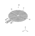
- FIG. 2 is a perspective view showing an example of the cold trap 20.
- 3A is a plan view of the cold trap 20, and
- FIG. 3B is a side view thereof.
- the cold trap 20 is formed in a tube shape as described above, and includes, for example, two cooling tubes 21 and 22 arranged in the vertical direction. These cooling tubes 21 and 22 are curved so as to have predetermined intervals (gap) 21a and 22a, and are formed by being folded at a plurality of locations, and as a whole, spread in a circular shape when viewed in plan. Become. As described above, the cooling tubes 21 and 22 are formed so as to spread when seen in a plane, whereby the water vapor collecting area in the freezing tank 10 can be widened. Moreover, since the collection area is large, a strong pressure difference does not occur in the freezing tank 10, and the particulate raw material after freezing (hereinafter referred to as frozen particles) is attracted to the cold trap 20 side. Can be prevented.
- frozen particles particulate raw material after freezing
- FIG. 4 is a perspective view showing the lid 12 of the freezing tank 10 to which the cold trap 20 is attached. As shown in FIG. 4, each cooling tube is attached to the lid body 12 so that the introduction parts 21 b and 22 b and the lead-out parts 21 c and 22 c protrude outside the freezing tank 10. Connected to the source.
- the lid 12 is removed by the operator. Therefore, maintenance of the cold trap 20 attached to the lid 12 is also possible during the maintenance.
- the diameter r1 of the upper cooling tube 21 is such that the upper cooling tube 21 is disposed on the interval 22a (see FIG. 3A) of the lower cooling tube 22.
- it is formed smaller than the diameter r2 of the lower cooling tube 22.
- An opening 23 is provided at the center of each cooling tube 21, 22.
- the opening 23 and the nozzle 9 attached to the lid body 12 face each other, and the nozzle 9 injects the raw material liquid F substantially downward through the opening 23.
- a cover 19 that prevents the raw material liquid F sprayed from the nozzle 9 from scattering toward the cooling tubes 21 and 22 is inserted through the opening 23.
- the cover 19 is not always necessary.
- the shelf 16 is disposed at a height position closer to the bottom surface 10b than the ceiling surface 10a of the freezing tank 10, and the cold trap 20 is disposed at a height position closer to the ceiling surface 10a than the shelf 16 disposed at the height position.
- the height h1 of the shelf 16 from the receiving surface for receiving the raw material (the upper surface of the shelf 16) to the cold trap 20 is, for example, 1 m or more, but may be shorter than this depending on the processing conditions.
- the processing conditions are, for example, the type of raw material, the flow rate of the raw material liquid F from the nozzle 9, the degree of vacuum in the freezing tank 10, the temperature of heat treatment of the shelf 16, and the like.
- a recovery container 13 for recovering the lyophilized raw material is connected to the bottom of the freezing tank 10 via a recovery path 15.
- the operations such as the exhaust valve 2, the vacuum pump 1, the open / close valves 5 and 6, the rotation of the shelf 16, the vibration of the shelf 16 and the like are controlled by a control unit (not shown).
- freeze-drying apparatus 100 configured as described above will be described.
- the exhaust valve 2 When the exhaust valve 2 is opened and the vacuum pump 1 is operated, the inside of the freezing tank 10 is depressurized and maintained at a predetermined degree of vacuum.
- the shelf 16 is in a horizontal state as shown in FIG.
- the on-off valves 5 and 7 are opened, the raw material liquid F is supplied to the nozzle 9 by gas pressure, and the raw material liquid F is injected from the nozzle 9 into the freezing tank 10.
- the raw material liquid F may be precooled before being supplied into the freezing tank 10.
- the raw material liquid F sprayed from the nozzle 9 is a liquid containing water as a solvent until the middle of dropping, but the water evaporates or sublimates from the middle of the raw material liquid F falling, and the endothermic action at that time. As a result, the raw material is frozen.
- the raw material is dried by freezing the raw material, that is, when water vapor is released from the raw material.
- the raw material is frozen includes the case where at least all or a part of the surface of the raw material is frozen, and the raw material is frozen on the shelf 16 so that the raw material does not stick to the shelf 16. Means state.
- the shelf 16 is cooled by the cooling mechanism. Thereby, the freezing action of the raw material particles is promoted, and the productivity of the particles is improved.
- the temperature of the receiving surface of the shelf 16 by the cooling mechanism is, for example, ⁇ 60 to 0 ° C. (0 ° C., ⁇ 15 ° C., ⁇ 20 ° C., ⁇ 22.5 ° C., ⁇ 25 ° C., ⁇ 30 ° C., ⁇ 40 ° C., ⁇ 50 ° C, -60 ° C, or other temperature).
- the shelf 16 vibrates in the horizontal direction by the operation of the vibration generator 31 during the injection of the raw material liquid F, after the injection, or immediately before and after the injection.
- the frozen particles deposited on the shelf 16 are uniformly diffused on the shelf 16 so as to reduce the deposition thickness or to form a single layer. Thereby, the freezing efficiency and drying efficiency of each particle are improved.
- the shelf 16 is heated by the heating mechanism.
- grains is accelerated
- the drying process by the heating mechanism is referred to as heat drying, and is distinguished from the drying by freezing.
- the temperature of the deposition surface of the shelf 16 by the heating mechanism is set to 20 to 50 ° C. (20, 40, 50 ° C., or other temperature), for example.
- the shelf 16 When the freeze-drying of the frozen particles is completed, the shelf 16 is tilted by the tilt mechanism 35 as shown in FIG. 5, and the shelf 16 is vibrated by the operation of the vibration generator 32. Thereby, the dry particles are collected in the collection container 13 through the collection path 15 by the dead weight of the dried particles (particles after the heat drying is finished) and by acceleration due to vibration.
- the vibration direction by the vibration generator 32 is substantially horizontal, but may be the direction of the inclination or other directions.
- the raw material in the raw material liquid F sprayed from the nozzle 9 evaporates or sublimates the water vapor during the fall.
- the raw material liquid F is jetted from the nozzle 9 through the openings 23 provided in the cooling tubes 21 and 22, the height in the freezing tank 10 when the raw material is frozen.
- the vertical position and the height position of the cold trap 20 are separated from each other to some extent. Therefore, it can prevent that a raw material is drawn near to the cold trap 20 side with water vapor
- FIG. 6 is a schematic diagram showing a freeze-drying apparatus according to another embodiment of the present invention.
- the same members, functions, and the like included in the freeze-drying apparatus 200 according to the embodiment shown in FIG. 1 and the like will be simplified or omitted, and different points will be mainly described.
- the nozzle 9 is disposed on the side surface 10d of the freezing tank 10 which is a vacuum chamber, and the raw material liquid F is ejected substantially in the horizontal direction.
- the height position of the nozzle 9 may be lower than the position shown in FIG.
- the nozzle 9 may be arranged at about half the distance between the cold trap 20 and the upper surface of the shelf 16 or at a height position closer to the shelf 16 than half of the distance.
- FIG. 7 is a schematic view showing a freeze-drying apparatus according to still another embodiment of the present invention.
- the lyophilization apparatus 300 shown in FIG. 7 includes a raw material liquid supply pipe 28 that extends from the outside of the freezing tank 10 to the inside on the side surface 10 d of the freezing tank 10.
- a nozzle 9 is connected to an end portion of the raw material liquid supply pipe 28 extending in the freezing tank 10, and the nozzle 9 ejects the raw material liquid F substantially upward.
- FIG. 8 is a schematic diagram showing a freeze-drying apparatus according to still another embodiment of the present invention.
- the shelf 16 provided in the freezing tank 10 of the freeze-drying apparatus 400 is, for example, the first shelf member 16a and the second shelf at the center thereof by two inclined mechanisms 35. It is divided into members 16b. Of course, the shelf 16 may be divided into three or more by three or more tilt mechanisms 35.
- Vibration is given to the shelves 16 (16a and 16b) which are divided into two and are inclined by vibration generators 32 and 32, respectively.
- the heat-dried (and / or frozen) particles are recovered in the recovery container 13 via the recovery path 15 provided in the center of the bottom surface 10b of the freezing tank 10.
- FIG. 9 is a schematic view showing a freeze-drying apparatus according to still another embodiment of the present invention.
- a plurality of vibration generators 33 are attached to the side surface of the freezing tank 10 of the freeze-drying apparatus 500 as a diffusion mechanism for vibrating the freezing tank 10.
- the vibration generator 33 is a vibration motor having a counterweight 34, for example.
- the two vibration generators 33 are provided, for example, so as to be opposed to each other at a position 180 ° apart when viewed in a plane.
- a coil spring 17 is provided on the outer surface 10 d of the freezing tank 10 via a spring mounting portion 10 e, and the freezing tank 10 is installed on the floor surface 24 via these coil springs 17. Thereby, the freezing tank 10 can vibrate.
- the vibration phase of both vibration generators 33 is controlled so that the freezing tank 10 substantially vibrates in the vertical direction. Alternatively, it may be controlled so that the freezing tank 10 vibrates substantially horizontally.
- FIG. 10 is a schematic diagram showing a freeze-drying apparatus according to still another embodiment of the present invention.
- the freeze-drying apparatus 800 is an apparatus according to a combination of the freeze-drying apparatuses 400 and 500. That is, a vibration generator 33 that vibrates the freezing tank 10 is provided as a diffusion mechanism, and the shelf 16 can be divided into a plurality of shelf members (16a and 16b).
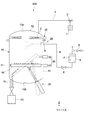
- FIG. 11 is a schematic diagram showing a freeze-drying apparatus according to still another embodiment of the present invention.
- the vacuum chamber 60 has a freezing tank 40 and a drying tank 50 that is long in one direction (X-axis direction).
- An opening 40 a is provided in the lower part of the freezing tank 40.
- the freezing tank 40 and the drying tank 50 are hermetically connected by the opening 40 a being connected to the opening 50 a provided in the upper part of the drying tank 50 via the bellows 26.
- a nozzle 9 for injecting the raw material liquid F supplied from the container 4 for storing the raw material liquid F is provided.
- the vacuum pump 1 is connected to the drying tank 50 through the exhaust pipe 3 and the exhaust valve 2.
- the drying tank 50 is provided with a shelf 29 that constitutes a transfer path extending in a predetermined direction, and the particle collection container 13 is connected to the side opposite to the side where the opening 50a of the drying tank 50 is provided. Yes.
- the shelf 29 receives the frozen particles falling from the freezing tank 40 via the bellows 26, and moves the received frozen particles in a predetermined direction by vibration.
- the shelf 29 may be configured to be heat-treated by a heating mechanism and a cooling mechanism.
- a vibration generator 33 that vibrates the drying tank 50 is attached to the outer surface of the drying tank 50.
- the vibration generator 33 for example, a vibration motor having a counterweight 34 shown in FIGS. 9 and 10 may be used. Further, the number of vibration generators 33 is not limited.
- a coil spring 17 is provided on the outer surface of the drying tank 50 via a spring mounting portion 50 e, and the drying tank 50 is installed on the floor surface 24 via the coil spring 17. Thereby, the drying tank 50 can be vibrated.
- the vibration generator 33 changes the angle of attachment to the drying tank 50 obliquely with respect to the horizontal direction (X-axis direction), thereby causing the vibration in the oblique direction in the XZ plane. Can be generated.
- the drying tank 50 vibrates in the oblique direction, the frozen particles are transferred in a predetermined direction, and the mounting angle of the vibration generator 33 to the drying tank 50 is changed, so that the transfer speed of the frozen particles is variably controlled. Is done.
- the attachment angle of the vibration generator 33 to the drying tank 50 may be automatically changed by a worker's manual work or a mechanism for controlling the angle.
- the vibration generator 33 can diffuse the frozen particles accumulated on the shelf 29 by the vibration.
- the angle at which the vibration generator 33 is attached to the drying tank 50 may be substantially horizontal, or may be a predetermined angle, which may serve both as diffusion and transfer of frozen particles.
- a cold trap 120 is connected to the drying tank 50. Water vapor evaporated or sublimated from the raw material liquid F injected mainly in the freezing tank 40 is collected by the cold trap 120 in the drying tank 50.
- the overall shape seen in the plane of the cold trap 120 may be designed according to the shape of the ceiling surface 10a of the drying tank 50, for example, but if the area seen in the Z-axis direction is designed to be as large as possible. Any shape is acceptable. Further, the cold trap 120 may have a tube shape as described above, a plate shape, or other shapes.
- the height h2 of the freezing tank 40 is, for example, 1.5 m or more, but is not limited thereto. Moreover, although the height h3 from the surface of the shelf 29 to the cold trap 120 is about 1 m, this is not limited to this value.
- freeze-drying apparatus 600 configured as described above will be described.
- Particles that are sprayed from the nozzle 9, dropped, and frozen are deposited on the shelf 29 of the drying tank 50 through the bellows 26.
- the cooling mechanism is provided in the shelf 29, the shelf 29 is cooled at this time, and the freezing action is promoted.
- the freezing particles accumulated on the shelf 29 are diffused when the vibration generator 33 vibrates the drying tank 50.
- the timing of starting the vibration of the drying tank 50 is typically before spraying the raw material liquid, but may be during spraying or after spraying. Thereafter, the angle of the vibration generator 33 is changed, and the dry particles are transferred to the collection container 13 side. Alternatively, both particle diffusion and transport may occur simultaneously.
- the vibration of the drying tank 50 is absorbed by the bellows 26 and is not transmitted to the freezing tank 40, or even if it is transmitted, the vibration is attenuated to a vibration that does not adversely affect the freezing tank 40.
- the shelf 29 When the shelf 29 is provided with a heating mechanism, the shelf 29 is heated, and the frozen particles on the shelf 29 are promoted to dry by heating. The particles transferred to the collection container 13 fall to the collection container 13 and are collected.
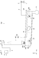
- FIG. 12 is a schematic diagram showing a freeze-drying apparatus according to still another embodiment of the present invention.
- the freeze-drying apparatus 700 differs from the freeze-drying apparatus 600 shown in FIG. 11 in that the longitudinal direction of the drying tank 50 is inclined with respect to the horizontal direction (X-axis direction).
- the vibration generator 33 may be attached to the shelf 29 of the drying tank 50 so as to generate a vibration component in an oblique direction with respect to the shelf 29.
- Embodiments according to the present invention are not limited to the embodiments described above, and other various embodiments are conceivable.
- the shelf 16 and the shelf 29 are both provided with a heating mechanism and a cooling mechanism.
- the structure in which any one of them is provided may be sufficient.
- the configuration in which the drying tank 50 vibrates is shown, but the drying tank 50 does not vibrate, and the shelf 29 may vibrate at least for the diffusion of frozen particles.
Landscapes
- Engineering & Computer Science (AREA)
- Health & Medical Sciences (AREA)
- Life Sciences & Earth Sciences (AREA)
- Molecular Biology (AREA)
- Mechanical Engineering (AREA)
- General Engineering & Computer Science (AREA)
- Nutrition Science (AREA)
- Chemical & Material Sciences (AREA)
- Food Science & Technology (AREA)
- Polymers & Plastics (AREA)
- Drying Of Solid Materials (AREA)
- Freezing, Cooling And Drying Of Foods (AREA)
Abstract
Priority Applications (5)
| Application Number | Priority Date | Filing Date | Title |
|---|---|---|---|
| CN200980126514.9A CN102089605B (zh) | 2008-07-10 | 2009-07-08 | 冷冻干燥装置和冷冻干燥方法 |
| KR1020117000293A KR101280159B1 (ko) | 2008-07-10 | 2009-07-08 | 동결 건조 장치 및 동결 건조 방법 |
| EP09794465.6A EP2320185B1 (fr) | 2008-07-10 | 2009-07-08 | Dispositif de lyophilisation |
| US13/003,002 US8978268B2 (en) | 2008-07-10 | 2009-07-08 | Freeze-drying apparatus and freeze-drying method |
| JP2010519796A JP5386487B2 (ja) | 2008-07-10 | 2009-07-08 | 凍結乾燥装置 |
Applications Claiming Priority (2)
| Application Number | Priority Date | Filing Date | Title |
|---|---|---|---|
| JP2008-180124 | 2008-07-10 | ||
| JP2008180124 | 2008-07-10 |
Publications (1)
| Publication Number | Publication Date |
|---|---|
| WO2010005021A1 true WO2010005021A1 (fr) | 2010-01-14 |
Family
ID=41507134
Family Applications (1)
| Application Number | Title | Priority Date | Filing Date |
|---|---|---|---|
| PCT/JP2009/062426 WO2010005021A1 (fr) | 2008-07-10 | 2009-07-08 | Dispositif de lyophilisation et procédé de lyophilisation |
Country Status (6)
| Country | Link |
|---|---|
| US (1) | US8978268B2 (fr) |
| EP (1) | EP2320185B1 (fr) |
| JP (1) | JP5386487B2 (fr) |
| KR (1) | KR101280159B1 (fr) |
| CN (1) | CN102089605B (fr) |
| WO (1) | WO2010005021A1 (fr) |
Cited By (7)
| Publication number | Priority date | Publication date | Assignee | Title |
|---|---|---|---|---|
| JP2011229477A (ja) * | 2010-04-28 | 2011-11-17 | Morinaga & Co Ltd | 凍結乾燥食品及びその製造方法 |
| WO2012131935A1 (fr) * | 2011-03-30 | 2012-10-04 | トヨタ自動車株式会社 | Dispositif d'inspection de brouillard |
| JP2012211784A (ja) * | 2011-03-30 | 2012-11-01 | Toyota Motor Corp | 噴霧検査装置 |
| US11175093B1 (en) | 2020-05-18 | 2021-11-16 | MII Ltd. | Vacuum freeze-drying apparatus and vacuum freeze-drying method |
| WO2021235459A1 (fr) | 2020-05-18 | 2021-11-25 | 株式会社エムアイアイ | Dispositif de lyophilisation sous vide et procédé de lyophilisation sous vide |
| US11320200B1 (en) * | 2021-02-16 | 2022-05-03 | Ulvac, Inc. | Freeze-drying device and freeze-drying method |
| WO2023013630A1 (fr) | 2021-08-03 | 2023-02-09 | 株式会社エムアイアイ | Produit lyophilisé |
Families Citing this family (11)
| Publication number | Priority date | Publication date | Assignee | Title |
|---|---|---|---|---|
| WO2010005021A1 (fr) | 2008-07-10 | 2010-01-14 | 株式会社アルバック | Dispositif de lyophilisation et procédé de lyophilisation |
| JP5362121B2 (ja) * | 2010-10-29 | 2013-12-11 | 株式会社アルバック | 凍結真空乾燥装置及び凍結粒子製造方法 |
| KR20160074071A (ko) | 2014-12-18 | 2016-06-28 | 빌리브마이크론(주) | 안테나 자동 매칭을 수행하는 rfid 리더기 |
| ES2760075T3 (es) * | 2015-06-01 | 2020-05-13 | Ima Life North America Inc | Liofilización a granel utilizando congelación por pulverización y secado en agitación con calentamiento |
| WO2017078639A1 (fr) * | 2015-11-05 | 2017-05-11 | Türkyilmaz Murat | Séchoir avec simulation de rayonnement solaire |
| KR102097686B1 (ko) | 2016-10-05 | 2020-05-26 | 메디칸(주) | 회전동결건조 장치 및 방법 |
| US10040637B2 (en) * | 2016-10-25 | 2018-08-07 | Rec Silicon Inc | Oscillatory feeder |
| WO2022104274A1 (fr) * | 2020-11-16 | 2022-05-19 | Sublime Stericeuticals Corporation | Remplisseuse de poudre/lyophilisateur à débit continu à l'intérieur d'une limite stérile |
| CN113108557B (zh) * | 2021-03-29 | 2022-06-14 | 北京善在量子健康科技有限公司 | 一种冻干机冷阱玻璃罩使用辅助装置 |
| CN113606879B (zh) * | 2021-08-12 | 2022-08-26 | 四川和诚振药科技有限公司 | 一种通过振动混合实现超快速无团聚真空冷冻干燥的装置 |
| CN113606880B (zh) * | 2021-08-12 | 2022-11-15 | 四川和诚振药科技有限公司 | 利用高加速度振动实现动态超快速无团聚冷冻干燥的方法 |
Citations (2)
| Publication number | Priority date | Publication date | Assignee | Title |
|---|---|---|---|---|
| JP2003207268A (ja) * | 2002-01-11 | 2003-07-25 | Okawara Mfg Co Ltd | 液体原料を用いた粉粒体の製造方法並びに粉粒体製造装置 |
| JP2005168904A (ja) * | 2003-12-12 | 2005-06-30 | Ulvac Japan Ltd | 噴霧式真空乾燥法による封入装置 |
Family Cites Families (12)
| Publication number | Priority date | Publication date | Assignee | Title |
|---|---|---|---|---|
| FR1211320A (fr) | 1956-04-18 | 1960-03-15 | Procédé et appareil à déshydrater dans une enceinte | |
| US3362835A (en) * | 1964-01-15 | 1968-01-09 | Fmc Corp | Spray freeze drying system |
| US3445247A (en) * | 1964-10-08 | 1969-05-20 | Basic Vegetable Products Inc | Freeze dried product and process for producing the same |
| GB1171929A (en) * | 1966-12-20 | 1969-11-26 | Hills Bros Coffee | Improvements in or relating to Freeze-Drying methods and apparatus |
| US4670993A (en) * | 1984-08-16 | 1987-06-09 | E.C.C. America Inc. | Method for fluidizing fine kaolin particles |
| JP3867267B2 (ja) * | 2001-12-28 | 2007-01-10 | 株式会社大川原製作所 | 液体原料を用いる粉粒体製造装置及びこの装置を用いた粉粒体の製造方法 |
| JP3942093B2 (ja) * | 2003-01-28 | 2007-07-11 | 株式会社アルバック | 噴霧式真空凍結乾燥装置 |
| EP1742716A4 (fr) * | 2004-05-01 | 2009-02-25 | Agres Ltd | Procede et appareil de sechage |
| JP4180551B2 (ja) * | 2004-09-27 | 2008-11-12 | 株式会社アルバック | 凍結真空乾燥装置および凍結真空乾燥方法 |
| JP2006177640A (ja) | 2004-12-24 | 2006-07-06 | Ulvac Japan Ltd | 凍結真空乾燥装置 |
| US7650985B2 (en) * | 2006-11-08 | 2010-01-26 | Sandvik Mining & Construction Australia Pty Ltd | Closure system for a trough |
| WO2010005021A1 (fr) | 2008-07-10 | 2010-01-14 | 株式会社アルバック | Dispositif de lyophilisation et procédé de lyophilisation |
-
2009
- 2009-07-08 WO PCT/JP2009/062426 patent/WO2010005021A1/fr active Application Filing
- 2009-07-08 US US13/003,002 patent/US8978268B2/en active Active
- 2009-07-08 EP EP09794465.6A patent/EP2320185B1/fr active Active
- 2009-07-08 JP JP2010519796A patent/JP5386487B2/ja active Active
- 2009-07-08 KR KR1020117000293A patent/KR101280159B1/ko active IP Right Grant
- 2009-07-08 CN CN200980126514.9A patent/CN102089605B/zh active Active
Patent Citations (2)
| Publication number | Priority date | Publication date | Assignee | Title |
|---|---|---|---|---|
| JP2003207268A (ja) * | 2002-01-11 | 2003-07-25 | Okawara Mfg Co Ltd | 液体原料を用いた粉粒体の製造方法並びに粉粒体製造装置 |
| JP2005168904A (ja) * | 2003-12-12 | 2005-06-30 | Ulvac Japan Ltd | 噴霧式真空乾燥法による封入装置 |
Cited By (18)
| Publication number | Priority date | Publication date | Assignee | Title |
|---|---|---|---|---|
| JP2011229477A (ja) * | 2010-04-28 | 2011-11-17 | Morinaga & Co Ltd | 凍結乾燥食品及びその製造方法 |
| WO2012131935A1 (fr) * | 2011-03-30 | 2012-10-04 | トヨタ自動車株式会社 | Dispositif d'inspection de brouillard |
| JP2012211784A (ja) * | 2011-03-30 | 2012-11-01 | Toyota Motor Corp | 噴霧検査装置 |
| CN103460016A (zh) * | 2011-03-30 | 2013-12-18 | 丰田自动车株式会社 | 喷雾检查装置 |
| JP5692361B2 (ja) * | 2011-03-30 | 2015-04-01 | トヨタ自動車株式会社 | 噴霧検査装置 |
| US9116085B2 (en) | 2011-03-30 | 2015-08-25 | Toyota Jidosha Kabushiki Kaisha | Mist testing device |
| US20230100406A1 (en) * | 2020-05-18 | 2023-03-30 | Mii, Ltd. | Vacuum freeze-drying apparatus and vacuum freeze-drying method |
| WO2021235459A1 (fr) | 2020-05-18 | 2021-11-25 | 株式会社エムアイアイ | Dispositif de lyophilisation sous vide et procédé de lyophilisation sous vide |
| KR20220154833A (ko) | 2020-05-18 | 2022-11-22 | 카부시키가이샤 엠아이아이 | 진공동결건조장치 및 진공동결건조방법 |
| US11175093B1 (en) | 2020-05-18 | 2021-11-16 | MII Ltd. | Vacuum freeze-drying apparatus and vacuum freeze-drying method |
| US11644236B2 (en) | 2020-05-18 | 2023-05-09 | Mii, Ltd. | Vacuum freeze-drying apparatus and vacuum freeze-drying method |
| US11320200B1 (en) * | 2021-02-16 | 2022-05-03 | Ulvac, Inc. | Freeze-drying device and freeze-drying method |
| US11480390B2 (en) | 2021-02-16 | 2022-10-25 | Ulvac, Inc. | Freeze-drying device and freeze-drying method |
| US11732965B2 (en) | 2021-02-16 | 2023-08-22 | Ulvac, Inc. | Freeze-drying device and freeze-drying method |
| WO2023013630A1 (fr) | 2021-08-03 | 2023-02-09 | 株式会社エムアイアイ | Produit lyophilisé |
| KR20230164181A (ko) | 2021-08-03 | 2023-12-01 | 카부시키가이샤 엠아이아이 | 동결 건조물 |
| US20240085107A1 (en) * | 2021-08-03 | 2024-03-14 | MII Ltd. | Freeze-dried product |
| US11940214B1 (en) | 2021-08-03 | 2024-03-26 | Mii, Ltd. | Freeze-dried product |
Also Published As
| Publication number | Publication date |
|---|---|
| US8978268B2 (en) | 2015-03-17 |
| KR101280159B1 (ko) | 2013-06-28 |
| US20110192047A1 (en) | 2011-08-11 |
| EP2320185B1 (fr) | 2016-08-24 |
| EP2320185A1 (fr) | 2011-05-11 |
| JP5386487B2 (ja) | 2014-01-15 |
| KR20110015687A (ko) | 2011-02-16 |
| EP2320185A4 (fr) | 2014-06-25 |
| CN102089605A (zh) | 2011-06-08 |
| JPWO2010005021A1 (ja) | 2012-01-05 |
| CN102089605B (zh) | 2015-01-21 |
Similar Documents
| Publication | Publication Date | Title |
|---|---|---|
| JP5386487B2 (ja) | 凍結乾燥装置 | |
| JP5230034B2 (ja) | 凍結乾燥装置 | |
| JP5230033B2 (ja) | 凍結乾燥装置 | |
| US8341854B2 (en) | Vacuum freeze-drying apparatus and method for vacuum freeze drying | |
| JP4180551B2 (ja) | 凍結真空乾燥装置および凍結真空乾燥方法 | |
| JP6518778B2 (ja) | 基板処理装置および基板処理方法 | |
| JP2017145507A (ja) | 直接液体堆積 | |
| US11448463B2 (en) | Freeze drying chamber for a bulk freeze drying system | |
| JP5362124B2 (ja) | 凍結真空乾燥装置 | |
| JP3867267B2 (ja) | 液体原料を用いる粉粒体製造装置及びこの装置を用いた粉粒体の製造方法 | |
| RU2353351C1 (ru) | Способ выделения из жидкой среды термочувствительных лекарственных препаратов и установка для его осуществления | |
| JP2004093078A (ja) | 真空乾燥機への原料液供給方法並びにその装置 | |
| JP2019214767A (ja) | 真空蒸着装置用の蒸着源 |
Legal Events
| Date | Code | Title | Description |
|---|---|---|---|
| WWE | Wipo information: entry into national phase |
Ref document number: 200980126514.9 Country of ref document: CN |
|
| 121 | Ep: the epo has been informed by wipo that ep was designated in this application |
Ref document number: 09794465 Country of ref document: EP Kind code of ref document: A1 |
|
| WWE | Wipo information: entry into national phase |
Ref document number: 2010519796 Country of ref document: JP |
|
| ENP | Entry into the national phase |
Ref document number: 20117000293 Country of ref document: KR Kind code of ref document: A |
|
| WWE | Wipo information: entry into national phase |
Ref document number: 13003002 Country of ref document: US |
|
| NENP | Non-entry into the national phase |
Ref country code: DE |
|
| REEP | Request for entry into the european phase |
Ref document number: 2009794465 Country of ref document: EP |
|
| WWE | Wipo information: entry into national phase |
Ref document number: 2009794465 Country of ref document: EP |