WO2009157195A1 - マイクロホン装置 - Google Patents
マイクロホン装置 Download PDFInfo
- Publication number
- WO2009157195A1 WO2009157195A1 PCT/JP2009/002900 JP2009002900W WO2009157195A1 WO 2009157195 A1 WO2009157195 A1 WO 2009157195A1 JP 2009002900 W JP2009002900 W JP 2009002900W WO 2009157195 A1 WO2009157195 A1 WO 2009157195A1
- Authority
- WO
- WIPO (PCT)
- Prior art keywords
- microphone device
- unit
- microphone
- sound
- head
- Prior art date
Links
Images


Classifications
-
- H—ELECTRICITY
- H04—ELECTRIC COMMUNICATION TECHNIQUE
- H04R—LOUDSPEAKERS, MICROPHONES, GRAMOPHONE PICK-UPS OR LIKE ACOUSTIC ELECTROMECHANICAL TRANSDUCERS; DEAF-AID SETS; PUBLIC ADDRESS SYSTEMS
- H04R3/00—Circuits for transducers, loudspeakers or microphones
- H04R3/005—Circuits for transducers, loudspeakers or microphones for combining the signals of two or more microphones
-
- B—PERFORMING OPERATIONS; TRANSPORTING
- B60—VEHICLES IN GENERAL
- B60R—VEHICLES, VEHICLE FITTINGS, OR VEHICLE PARTS, NOT OTHERWISE PROVIDED FOR
- B60R11/00—Arrangements for holding or mounting articles, not otherwise provided for
- B60R11/02—Arrangements for holding or mounting articles, not otherwise provided for for radio sets, television sets, telephones, or the like; Arrangement of controls thereof
- B60R11/0247—Arrangements for holding or mounting articles, not otherwise provided for for radio sets, television sets, telephones, or the like; Arrangement of controls thereof for microphones or earphones
-
- B—PERFORMING OPERATIONS; TRANSPORTING
- B60—VEHICLES IN GENERAL
- B60R—VEHICLES, VEHICLE FITTINGS, OR VEHICLE PARTS, NOT OTHERWISE PROVIDED FOR
- B60R1/00—Optical viewing arrangements; Real-time viewing arrangements for drivers or passengers using optical image capturing systems, e.g. cameras or video systems specially adapted for use in or on vehicles
- B60R1/12—Mirror assemblies combined with other articles, e.g. clocks
- B60R2001/1284—Mirror assemblies combined with other articles, e.g. clocks with communication systems other than radio-receivers, e.g. keyless entry systems, navigation systems; with anti-collision systems
-
- H—ELECTRICITY
- H04—ELECTRIC COMMUNICATION TECHNIQUE
- H04R—LOUDSPEAKERS, MICROPHONES, GRAMOPHONE PICK-UPS OR LIKE ACOUSTIC ELECTROMECHANICAL TRANSDUCERS; DEAF-AID SETS; PUBLIC ADDRESS SYSTEMS
- H04R2410/00—Microphones
- H04R2410/01—Noise reduction using microphones having different directional characteristics
-
- H—ELECTRICITY
- H04—ELECTRIC COMMUNICATION TECHNIQUE
- H04R—LOUDSPEAKERS, MICROPHONES, GRAMOPHONE PICK-UPS OR LIKE ACOUSTIC ELECTROMECHANICAL TRANSDUCERS; DEAF-AID SETS; PUBLIC ADDRESS SYSTEMS
- H04R2499/00—Aspects covered by H04R or H04S not otherwise provided for in their subgroups
- H04R2499/10—General applications
- H04R2499/13—Acoustic transducers and sound field adaptation in vehicles
Definitions
- the present invention relates to a microphone device mounted on an automobile aiming at directional sound collection of speaker voice in the automobile.
- the conventional microphone device includes a directional microphone 103 having directivity, and a rotary disc 102 on which the directional microphone 103 is disposed, and the rotary disc 102 is disposed to electrically and mechanically connect to the automobile.
- a microphone assembly 101 is shown.
- An arrow 104 is a direction in which the sensitivity of the directional microphone 103 is maximized, that is, the directivity direction 104.
- the directivity direction 104 is rotated by the rotation of the turntable 102.
- the rotary disc 102 is capable of rotationally adjusting the directivity direction 104 in the direction of the speaker to pick up and pick up a speaker's voice.
- the directivity direction 104 is the optimal direction. It takes time and effort to adjust the rotation of the rotary disc 102.
- the present invention has been made in view of the above circumstances, and an object of the present invention is to provide a microphone device capable of automatically adjusting the directivity of the microphone according to the position of the head of a passenger of a car.
- the microphone device is a microphone device mounted on a car, and includes a plurality of sound pickup units that generate an input signal according to a change in sound pressure caused by sound waves, and the position of the head of a predetermined passenger of the car. Calculation processing for performing predetermined directivity calculation processing on the input signal based on the position detection unit that detects the position of the head, the position of the head detected by the position detection unit, and the positions of the plurality of sound collection units Part.
- the directivity of the microphone can be automatically adjusted by considering the positional relationship between the position of the sound collection unit which is the microphone and the position of the head of the passenger.
- the arithmetic processing unit further determines a delay amount based on the position of the head detected by the position detection unit and the positions of the plurality of sound collection units, and the delay amount A signal delay unit for delaying the first input signal generated by the first sound collection unit, and a second sound collection unit other than the first input signal delayed by the signal delay unit and the first sound collection unit And an operation unit that performs predetermined addition / subtraction processing on the second input signal generated by the sound unit.
- the delay amount of the first input signal is determined in consideration of the positional relationship between the position of the sound collection unit which is a microphone and the position of the head of the passenger, and directivity calculation processing is performed based on the delay amount.
- the directivity of the microphone can be automatically adjusted.
- the position detection unit detects the position of the head based on a set angle of a rearview mirror provided on the vehicle.
- the position detection unit detects the position of the head based on a set position of a seat provided in the automobile.
- the position of the head of the passenger seated in the seat is detected from the set position of the seat, and the directivity of the microphone is automatically determined by considering the positional relationship with the sound collection unit which is the microphone. It is adjustable.
- the position detection unit detects the position of the head based on a captured image captured by an imaging unit provided in the vehicle.
- an image including the passenger is captured by the imaging unit, the position of the head of the passenger is detected from the captured image, and the positional relationship with the sound collection unit, which is a microphone, is automatically considered.
- the directivity of the microphone can be adjusted.
- the position detection unit captures an image by the setting angle of the rearview mirror provided in the vehicle, the setting position of a seat provided in the vehicle, and an imaging unit provided in the vehicle The position of the head is detected based on at least two of the captured images.
- the accuracy of one detection can be obtained by detecting the position of the passenger's head based on any two or more of the setting angle of the rearview mirror, the setting position of the seat, and the captured image captured by the imaging device.
- the directivity of the microphone can be adjusted more accurately.
- the sound collection unit is a directional microphone.
- the directivity of the microphone can be adjusted more accurately by using the directional microphone.
- the sound collection unit is a MEMS microphone.
- the microphone device can be miniaturized.
- the predetermined passenger includes a driver seat passenger and a passenger seat passenger of the vehicle.
- directivity can be obtained by setting the rearview mirror to an appropriate angle without changing the direction of the microphone. It can provide convenience that can direct the direction to the passenger.
- the microphone device in the embodiment of the present invention is characterized by using a position detector for detecting the position of the head of a speaker in a car (a predetermined passenger included in the passenger).
- the microphone device in the embodiment of the present invention is a microphone device mounted in an automobile, for example, installed on a ceiling surface or disposed in an automobile brought in from outside the automobile.
- FIG. 2 is a view showing an example of a microphone device using a position detector in an embodiment of the present invention.
- the microphone device 201 illustrated in FIG. 2 includes a position detector 202, sound collection elements 203 and 204, a signal processing unit 205, and an output unit 210.
- the signal processing unit 205 includes microphone amplifiers 206 and 207, a delay unit 208, and an arithmetic unit 209, and outputs an output signal of the sound collection element 203, an output signal of the sound collection element 204 and an output signal of the position detector 202. It is a signal processing unit that inputs and outputs the output signal of the computing unit 209.
- the sound collection element 203 and the sound collection element 204 are sound collection elements that output an electric signal according to a change in sound pressure caused by a sound wave. Although two sound collecting elements are shown in FIG. 2, the number of the sound collecting elements may not be two as long as it is plural. Also, the sound collection element may be a directional microphone. Also, the sound collection element may be a MEMS microphone.
- the microphone amplifier 206 is a microphone amplifier that drives the sound collection element 204 and amplifies and outputs the electric signal output from the sound collection element 204.
- the microphone amplifier 207 is a microphone amplifier that drives the sound collection element 203 and amplifies and outputs the electric signal output from the sound collection element 203.
- the position detector 202 is a position detector that detects the position of the head of the speaker in the vehicle based on predetermined position information, and outputs an electrical signal according to the detected position of the head.
- the set angle of the rearview mirror is detected as predetermined position information. That is, it has a function as a back mirror set angle detector.
- the set position of the seat provided in the car may be detected. That is, it may have a function as a seat setting position detector.
- the position detector 202 acquires an image captured by an imaging unit (for example, a camera directed to the direction of the face of the speaker) provided as a predetermined information on the car, and based on this, the position of the face of the speaker May be detected, and an electrical signal may be output according to the position of the detected face. That is, it has a function as a camera image face position detection unit.
- the face of the speaker is included in the head of the speaker.
- the position detector 202 may have a combination of a plurality of the above-described detectors instead of having only one function. The accuracy of position detection is improved by combining a plurality.
- the delay unit 208 is a delay unit that delays and outputs the electric signal output from the microphone amplifier 207 according to the output signal of the position detector 202.
- the arithmetic unit 209 performs arithmetic processing such as addition or subtraction on the electric signal output from the delay unit 208 and the electric signal output from the microphone amplifier 206 and outputs the result.
- the output unit 210 is an output unit for connecting an electrical signal output from the computing unit 209 to an external device.
- the sensitivity of the array microphone composed of a plurality of sound collection elements arranged at a predetermined position is utilized for the output of each sound collection element utilizing the fact that the acoustic path from the sound source to each sound collection element is different. It is known that it has directivity by applying an appropriate delay, addition and subtraction, and the like.
- the process of applying an appropriate delay and addition / subtraction as described above is also referred to as directivity operation process. It is general that there is a relationship of the following equation (1) between the directivity direction ⁇ of the addition / subtraction type microphone array composed of two sound collection elements and the delay amount ⁇ of the delay applied to the sound collection elements It is known to.
- the microphone device 201 uses the principle of an addition / subtraction type microphone array.
- ⁇ d cos ⁇ / c (1)
- ⁇ the delay amount
- d the distance between the two sound pickup elements
- ⁇ the directivity direction
- c the speed of sound
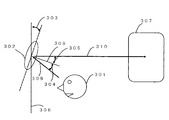
- FIG. 3 is a principle diagram for detecting the position of the head of the speaker based on the set angle of the rearview mirror provided on the car.
- the rearview mirror 302 is a rearview mirror for the driver's seat passenger 301 in the car to visually check the rear of the car through the rear glass 307.
- the perpendicular 308 of the surface of the rearview mirror 302 and the driver's seat passenger 301 are the rearview mirror 302 according to the principle of light reflection.
- the set angle 303 of the rearview mirror 302 determined based on, for example, the perpendicular line 306 of the contact surface of the automobile is uniquely determined. Therefore, the position of the head of the driver's seat in the car is detected by calculating from the set angle 303 of the rearview mirror 302.
- the rearview mirror 302 is set to an appropriate angle without changing the direction of the microphone. It is possible to provide the convenience that the direction of directivity can be directed to the speaker only by setting.
- the directivity direction ⁇ of the microphone device 201 may face not only the driver's seat but also the passenger's seat. Furthermore, it may be directed to a rear seat passenger. That is, any of the driver's seat passenger, the passenger's seat passenger and the rear seat passenger can be speakers who are the predetermined passengers of the car.
- the present invention is useful for a microphone device or the like capable of automatically adjusting the directivity of a microphone according to the position of the head of a speaker.
Abstract
話者の頭部の位置に応じて自動的にマイクロホンの指向性を調整可能なマイクロホン装置を提供する。 自動車に搭載されるマイクロホン装置201であって、音波による音圧変化に応じて入力信号を生成する複数の収音素子203、204と、自動車の所定の搭乗者の頭部の位置を検出する位置検出器202と、位置検出器202によって検出された頭部の位置および複数の収音素子203、204の位置に基づいて、入力信号に対して、指向性を有するよう演算処理を行う遅延器208および演算器209を有する。
Description
本発明は、自動車内の話者音声の指向性収音を目的とする自動車に搭載されるマイクロホン装置に関する。
従来のマイクロホン装置としては、例えば特許文献1に示すようなものがあった。これについて図1を用いて説明する。従来のマイクロホン装置においては、指向性を有する指向性マイクロホン103と、指向性マイクロホン103を配置する回転盤102とを具備し、回転盤102を配置し自動車と電気的および機械的に接続するためのマイクロホンアッセンブリ101である。矢印104は、指向性マイクロホン103の感度が最大になる方向即ち指向性方向104である。回転盤102が回転することにより指向性方向104は回転する。回転盤102はマイクロホンの指向性を任意の方向に回転調整するために指向性方向104を話者の方向へ回転調整して話者音声を狙って収音することを可能としている。
しかしながら、上記従来の構造においては、例えば座高や股下長さなどの体格が異なることにより、話者音声の音源位置である話者の頭部の位置が異なる場合、指向性方向104を最適な方向に調整しなければならず、回転盤102を回転調整する手間がかかっていた。
本発明は、上記事情に鑑みてなされたものであって、自動車の搭乗者の頭部の位置に応じて自動的にマイクロホンの指向性を調整可能なマイクロホン装置を提供することを目的とする。
本発明のマイクロホン装置は、自動車に搭載されるマイクロホン装置であって、音波による音圧変化に応じて入力信号を生成する複数の収音部と、前記自動車の所定の搭乗者の頭部の位置を検出する位置検出部と、前記位置検出部によって検出された頭部の位置および前記複数の収音部の位置に基づいて、前記入力信号に対して、所定の指向性演算処理を行う演算処理部と、を有する。
この構成により、マイクロホンである収音部の位置と搭乗者の頭部の位置との位置関係を考慮することで、自動的にマイクロホンの指向性を調整可能である。
また、本発明のマイクロホン装置は、前記演算処理部が、更に、前記位置検出部によって検出された頭部の位置および前記複数の収音部の位置に基づいて遅延量を決定し、前記遅延量により第1の収音部によって生成された第1の入力信号を遅延させる信号遅延部と、前記信号遅延部により遅延された第1の入力信号および第1の収音部以外の第2の収音部によって生成された第2の入力信号に対して、所定の加減算処理を行う演算部と、を有する。
この構成により、マイクロホンである収音部の位置と搭乗者の頭部の位置との位置関係を考慮して第1入力信号の遅延量を決定し、遅延量に基づいて指向性演算処理を行うことで、自動的にマイクロホンの指向性を調整可能である。
また、本発明のマイクロホン装置は、前記位置検出部が、前記自動車に備えられたバックミラーの設定角度に基づいて、前記頭部の位置を検出する。
この構成により、バックミラーの設定角度から頭部の位置を検出し、マイクロホンである収音部との位置関係を考慮することで、自動的にマイクロホンの指向性を調整可能である。
また、本発明のマイクロホン装置は、前記位置検出部が、前記自動車に備えられた座席の設定位置に基づいて、前記頭部の位置を検出する。
この構成により、座席の設定位置から座席に着席している搭乗者の頭部の位置を検出し、マイクロホンである収音部との位置関係を考慮することで、自動的にマイクロホンの指向性を調整可能である。
また、本発明のマイクロホン装置は、前記位置検出部が、前記自動車に備えられた撮像手段により撮像された撮影画像に基づいて、前記頭部の位置を検出する。
この構成により、撮像手段により搭乗者を含む画像を撮像し、その撮像画像から搭乗者の頭部の位置を検出し、マイクロホンである収音部との位置関係を考慮することで、自動的にマイクロホンの指向性を調整可能である。
また、本発明のマイクロホン装置は、前記位置検出部が、前記自動車に備えられたバックミラーの設定角度、前記自動車に備えられた座席の設定位置、および、前記自動車に備えられた撮像手段により撮像された撮影画像の少なくとも2つに基づいて、前記頭部の位置を検出する。
この構成により、バックミラーの設定角度、座席の設定位置、および、撮像手段により撮像された撮影画像のいずれか2つ以上により搭乗者の頭部の位置を検出することで、一検出の精度がより向上し、より的確にマイクロホンの指向性を調整可能である。
また、本発明のマイクロホン装置は、前記収音部が、指向性マイクロホンである。
この構成により、指向性マイクロホンを用いることで、より的確にマイクロホンの指向性を調整可能である。
また、本発明のマイクロホン装置は、前記収音部が、MEMSマイクロホンである。
この構成により、マイクロホン装置を小型化できる。
また、本発明のマイクロホン装置は、前記所定の搭乗者が、前記自動車の運転席乗車者および助手席乗車者を含む。
この構成により、運転席乗車者、助手席乗車者のいずれについても頭部の位置を検出することで、自動的にマイクロホンの指向性を調整可能である。さらに、後部座席乗車者についても同様である。
本発明によれば、例えば体格の違いにより、自動車の搭乗者の頭部の位置が変わるたびに、マイクロホンの向きを調整変更させることなく、バックミラーを適当な角度に設定するだけで指向性の方向を搭乗者に向けることができる簡便さを提供することが出来るものである。
以下、本発明の実施の形態について、図面を用いて説明する。
本発明の実施形態におけるマイクロホン装置は、自動車内の話者(搭乗者の中に含まれる所定の搭乗者)の頭部の位置を検出する位置検出器を使用することを特徴としている。
また、本発明の実施形態におけるマイクロホン装置は、例えば天井面に設置されている、自動車外から持ち込み自動車内に配置されるなど、自動車内に搭載されるマイクロホン装置である。
図2は、本発明の実施形態における位置検出器を用いたマイクロホン装置の一例を示す図である。図2に示すマイクロホン装置201は、位置検出器202、収音素子203および204、信号処理部205、出力部210を具備する。
また、信号処理部205は、マイクロホンアンプ206および207、遅延器208、演算器209を具備し、収音素子203の出力信号と収音素子204の出力信号と位置検出器202の出力信号とを入力し、演算器209の出力信号を出力する信号処理部である。
収音素子203および収音素子204は、音波による音圧変化に応じて電気信号を出力する収音素子である。なお、図2では収音素子を2つ示しているが、収音素子の数は複数であれば必ずしも2個でなくて良い。また、収音素子は指向性マイクロホンであっても良い。また、収音素子はMEMSマイクロホンであっても良い。
マイクロホンアンプ206は、収音素子204を駆動し収音素子204の出力する電気信号を増幅し出力するマイクロホンアンプである。
マイクロホンアンプ207は収音素子203を駆動し収音素子203の出力する電気信号を増幅し出力するマイクロホンアンプである。
位置検出器202は、所定の位置情報に基づいて自動車内の話者の頭部の位置を検出し、検出した頭部の位置に応じて電気信号を出力する位置検出器である。例えば、所定の位置情報として、バックミラーの設定角度を検出する。つまり、バックミラー設定角度検出器としての機能を有する。また、所定の情報として、自動車内に備えられた座席の設定位置を検出してもよい。つまり、座席設定位置検出器としての機能を有してもよい。また、位置検出器202は、所定の情報として自動車に備えられた撮像手段(例えば、話者の顔方向へ向けられたカメラ)による撮影画像を取得し、これに基づいて話者の顔の位置を検出し、検出した顔の位置に応じて電気信号を出力してもよい。つまり、カメラ画像顔位置検出部としての機能を有する。なお、本実施形態では、話者の顔は話者の頭部に含まれるものとする。
さらに、位置検出器202は、上記各検出器としての機能を1つだけ有するのではなく、複数組み合わせて有してもよい。複数組み合わせることで、位置検出の精度が向上する。
遅延器208は、位置検出器202の出力信号に応じてマイクロホンアンプ207の出力する電気信号を遅延させ出力する遅延器である。
演算器209は、遅延器208の出力する電気信号とマイクロホンアンプ206の出力する電気信号とを加算や減算等の演算処理を行い出力する。
出力部210は、演算器209が出力する電気信号を外部装置に繋ぐための出力部である。
ところで、所定の位置に配置した複数の収音素子で構成されたアレイマイクロホンの感度は、音源から個々の収音素子への音響パスが異なることを利用して、個々の収音素子の出力に適当な遅延と加減算等を施すことで、指向性を持つことが知られている。このように、適当な遅延と加減算等を施す処理を指向性演算処理とも称する。2個の収音素子から構成される加減算型マイクロホンアレイの指向性方向θと収音素子に施される遅延の遅延量τとの間には次式(1)の関係があることが一般的に知られている。マイクロホン装置201は、加減算型マイクロホンアレイの原理を用いたものである。
τ=dcosθ/c・・・(1)
なお、τは遅延量、dは2個の収音素子の距離、θは指向性方向、cは音速である。
なお、τは遅延量、dは2個の収音素子の距離、θは指向性方向、cは音速である。
ここで、遅延量τを適当な値にするための自動車内の話者の頭部の位置の検出方法について説明する。ここでは、位置検出器202が自動車に備えられたバックミラーの設定角度を検出する場合について考える。図3は、位置検出器202が自動車に備えられたバックミラーの設定角度に基づいて話者の頭部の位置を検出する原理図である。
バックミラー302は、自動車内の運転席乗車者301がリアガラス307を通じて自動車の後方を目視確認するためのバックミラーである。運転席乗車者301がバックミラー302を介してリアガラス307を通じて自動車の後方を目視確認するとき、光の反射の原理により、バックミラー302の作る面の垂線308と運転席乗車者301がバックミラー302を見る視線309との成す角304とバックミラー302の作る面の垂線308とバックミラーからリアガラス中央付近へと伸びる線310との成す角305とは等しい。このとき、たとえば自動車の接地面の垂線306を基準に定められるバックミラー302の設定角度303は一意的に定められる。したがって、自動車内の運転席乗車者の頭部の位置はバックミラー302の設定角度303から逆算して検出される。
バックミラーの設定角度303の情報から逆算して得られる運転席乗車者の頭部の位置と、収音素子203および204からなるマイクロホンアレイとの成す角θ(上記指向性方向θと同義)と、収音素子203と収音素子204との距離dと、式1の関係とに基づいて、マイクロホン装置201の指向性を話者である運転席乗車者の頭部へむけるために適当な遅延量τを求めることができる。
このようなマイクロホン装置201により、話者である運転席乗車者の頭部の位置が、例えば体格の違いにより変わるたびに、マイクロホンの向きを調整変更させることなく、バックミラー302を適当な角度に設定するだけで指向性の方向を話者に向けることができる簡便さを提供可能である。
なお、マイクロホン装置201の指向性方向θは、運転席乗車者だけでなく助手席乗車者を向いても良い。さらに後部座席乗車者へ向いていてもよい。つまり、運転席乗車者、助手席乗車者、後部座席乗車者のいずれもが、自動車の所定の搭乗者である話者となり得る。
本発明を詳細にまた特定の実施態様を参照して説明したが、本発明の精神と範囲を逸脱することなく様々な変更や修正を加えることができることは当業者にとって明らかである。
本出願は、2008年6月24日出願の日本特許出願No.2008-164297に基づくものであり、その内容はここに参照として取り込まれる。
本出願は、2008年6月24日出願の日本特許出願No.2008-164297に基づくものであり、その内容はここに参照として取り込まれる。
本発明は、話者の頭部の位置に応じて自動的にマイクロホンの指向性を調整可能なマイクロホン装置等に有用である。
101 マイクロホンアッセンブリ
102 回転盤
103 指向性マイクロホン
104 指向性方向(矢印)
201 マイクロホン装置
202 位置検出器
203 収音素子
204 収音素子
205 信号処理部
206 マイクロホンアンプ
207 マイクロホンアンプ
208 遅延器
209 演算器
210 出力部
301 運転席乗車者
302 バックミラー
303 設定角度
304 成す角
305 成す角
306 自動車の接地面の垂線
307 リアガラス
308 バックミラーの作る面の垂線
309 視線
310 バックミラーからリアガラス中央付近へ伸びる線
102 回転盤
103 指向性マイクロホン
104 指向性方向(矢印)
201 マイクロホン装置
202 位置検出器
203 収音素子
204 収音素子
205 信号処理部
206 マイクロホンアンプ
207 マイクロホンアンプ
208 遅延器
209 演算器
210 出力部
301 運転席乗車者
302 バックミラー
303 設定角度
304 成す角
305 成す角
306 自動車の接地面の垂線
307 リアガラス
308 バックミラーの作る面の垂線
309 視線
310 バックミラーからリアガラス中央付近へ伸びる線
Claims (9)
- 自動車に搭載されるマイクロホン装置であって、
音波による音圧変化に応じて入力信号を生成する複数の収音部と、
前記自動車の所定の搭乗者の頭部の位置を検出する位置検出部と、
前記位置検出部によって検出された頭部の位置および前記複数の収音部の位置に基づいて、前記入力信号に対して、所定の指向性演算処理を行う演算処理部と、
を有するマイクロホン装置。 - 請求項1に記載のマイクロホン装置であって、
前記演算処理部は、更に、
前記位置検出部によって検出された頭部の位置および前記複数の収音部の位置に基づいて遅延量を決定し、前記遅延量により第1の収音部によって生成された第1の入力信号を遅延させる信号遅延部と、
前記信号遅延部により遅延された第1の入力信号および第1の収音部以外の第2の収音部によって生成された第2の入力信号に対して、所定の加減算処理を行う演算部と、
を有するマイクロホン装置。 - 請求項1または2に記載のマイクロホン装置であって、
前記位置検出部は、前記自動車に備えられたバックミラーの設定角度に基づいて、前記頭部の位置を検出する
マイクロホン装置。 - 請求項1または2に記載のマイクロホン装置であって、
前記位置検出部は、前記自動車に備えられた座席の設定位置に基づいて、前記頭部の位置を検出する
マイクロホン装置。 - 請求項1または2に記載のマイクロホン装置であって、
前記位置検出部は、前記自動車に備えられた撮像手段により撮像された撮影画像に基づいて、前記頭部の位置を検出する
マイクロホン装置。 - 請求項1または2に記載のマイクロホン装置であって、
前記位置検出部は、前記自動車に備えられたバックミラーの設定角度、前記自動車に備えられた座席の設定位置、および、前記自動車に備えられた撮像手段により撮像された撮影画像の少なくとも2つに基づいて、前記頭部の位置を検出する
マイクロホン装置。 - 請求項1ないし6のいずれか1項に記載のマイクロホン装置であって、
前記収音部は、指向性マイクロホンである
マイクロホン装置。 - 請求項1ないし7のいずれか1項に記載のマイクロホン装置であって、
前記収音部は、MEMSマイクロホンである
マイクロホン装置。 - 請求項1ないし8のいずれか1項に記載のマイクロホン装置であって、
前記所定の搭乗者は、前記自動車の運転席乗車者および助手席乗車者を含む
マイクロホン装置。
Priority Applications (3)
| Application Number | Priority Date | Filing Date | Title |
|---|---|---|---|
| CN200980100312A CN101796852A (zh) | 2008-06-24 | 2009-06-24 | 麦克风装置 |
| EP09769905A EP2291001A4 (en) | 2008-06-24 | 2009-06-24 | MICROPHONE DEVICE |
| US12/676,476 US20100208914A1 (en) | 2008-06-24 | 2009-06-24 | Microphone device |
Applications Claiming Priority (2)
| Application Number | Priority Date | Filing Date | Title |
|---|---|---|---|
| JP2008-164297 | 2008-06-24 | ||
| JP2008164297A JP2010010749A (ja) | 2008-06-24 | 2008-06-24 | マイクロホン装置 |
Publications (1)
| Publication Number | Publication Date |
|---|---|
| WO2009157195A1 true WO2009157195A1 (ja) | 2009-12-30 |
Family
ID=41444267
Family Applications (1)
| Application Number | Title | Priority Date | Filing Date |
|---|---|---|---|
| PCT/JP2009/002900 WO2009157195A1 (ja) | 2008-06-24 | 2009-06-24 | マイクロホン装置 |
Country Status (5)
| Country | Link |
|---|---|
| US (1) | US20100208914A1 (ja) |
| EP (1) | EP2291001A4 (ja) |
| JP (1) | JP2010010749A (ja) |
| CN (1) | CN101796852A (ja) |
| WO (1) | WO2009157195A1 (ja) |
Cited By (1)
| Publication number | Priority date | Publication date | Assignee | Title |
|---|---|---|---|---|
| US10237648B2 (en) | 2015-06-01 | 2019-03-19 | Clarion Co., Ltd. | Sound collecting device, and method of controlling sound collecting device |
Families Citing this family (14)
| Publication number | Priority date | Publication date | Assignee | Title |
|---|---|---|---|---|
| US9274744B2 (en) | 2010-09-10 | 2016-03-01 | Amazon Technologies, Inc. | Relative position-inclusive device interfaces |
| DE102011008555A1 (de) * | 2011-01-14 | 2012-07-19 | Daimler Ag | Erfassen von Sprache eines Insassens in einem Innenraum eines Fahrzeugs |
| CN102275548B (zh) * | 2011-05-31 | 2013-12-18 | 浙江吉利汽车研究院有限公司 | 车载麦克风的调节装置 |
| CN103092557A (zh) * | 2011-11-01 | 2013-05-08 | 上海博泰悦臻网络技术服务有限公司 | 车载语音输入装置及方法 |
| EP2822292B1 (en) * | 2013-07-03 | 2016-05-25 | GN Netcom A/S | A car speakerphone with automatic adjustment of microphone directivity |
| US11199906B1 (en) | 2013-09-04 | 2021-12-14 | Amazon Technologies, Inc. | Global user input management |
| KR102033309B1 (ko) * | 2013-10-25 | 2019-10-17 | 현대모비스 주식회사 | 운전석 위치를 고려하는 빔 포밍 마이크 제어 장치 및 방법 |
| US9609408B2 (en) * | 2014-06-03 | 2017-03-28 | GM Global Technology Operations LLC | Directional control of a vehicle microphone |
| US10063967B2 (en) * | 2016-03-22 | 2018-08-28 | Panasonic Intellectual Property Management Co., Ltd. | Sound collecting device and sound collecting method |
| CN108650571B (zh) * | 2018-05-25 | 2020-06-02 | 四川音创伟业科技有限公司 | 一种麦克风支架调节方法、装置、终端及可读介质 |
| GB2575491A (en) * | 2018-07-12 | 2020-01-15 | Centricam Tech Limited | A microphone system |
| US10857909B2 (en) * | 2019-02-05 | 2020-12-08 | Lear Corporation | Electrical assembly |
| CN111601198B (zh) * | 2020-04-24 | 2022-03-11 | 达闼机器人有限公司 | 应用麦克风跟踪说话人的方法、装置及计算设备 |
| CN111688580B (zh) | 2020-05-29 | 2023-03-14 | 阿波罗智联(北京)科技有限公司 | 智能后视镜进行拾音的方法以及装置 |
Citations (8)
| Publication number | Priority date | Publication date | Assignee | Title |
|---|---|---|---|---|
| JPH10126876A (ja) * | 1996-10-23 | 1998-05-15 | Matsushita Electric Ind Co Ltd | 超指向性マイクロホン |
| JPH1118194A (ja) * | 1997-06-26 | 1999-01-22 | Fujitsu Ltd | マイクロホンアレイ装置 |
| JP2005536113A (ja) * | 2002-08-09 | 2005-11-24 | シュアー アクイジション ホールディングス インコーポレイテッド | 調和的ネスティングを有する遅延ネットワークマイクロフォン |
| JP2005354223A (ja) * | 2004-06-08 | 2005-12-22 | Toshiba Corp | 音源情報処理装置、音源情報処理方法、音源情報処理プログラム |
| JP2006186646A (ja) * | 2004-12-27 | 2006-07-13 | Kyocera Corp | 携帯端末 |
| JP2007168686A (ja) | 2005-12-26 | 2007-07-05 | Kojima Press Co Ltd | 車載用マイク装置 |
| JP2008137538A (ja) * | 2006-12-04 | 2008-06-19 | Kojima Press Co Ltd | 車両内で使用される電話用マイク装置 |
| JP2008164297A (ja) | 2006-12-26 | 2008-07-17 | Honda Motor Co Ltd | 電流センサおよび電流センサのオフセット除去方法 |
Family Cites Families (9)
| Publication number | Priority date | Publication date | Assignee | Title |
|---|---|---|---|---|
| US7415126B2 (en) * | 1992-05-05 | 2008-08-19 | Automotive Technologies International Inc. | Occupant sensing system |
| US5694259A (en) * | 1995-01-10 | 1997-12-02 | Brandin; Bertil A. | Apparatus for automating the adjustment of rearview mirrors |
| DE19812697A1 (de) * | 1998-03-23 | 1999-09-30 | Volkswagen Ag | Verfahren und Einrichtung zum Betrieb einer Mikrofonanordnung, insbesondere in einem Kraftfahrzeug |
| WO2001037519A2 (en) * | 1999-11-19 | 2001-05-25 | Gentex Corporation | Vehicle accessory microphone |
| US7920102B2 (en) * | 1999-12-15 | 2011-04-05 | Automotive Technologies International, Inc. | Vehicular heads-up display system |
| US20020031234A1 (en) * | 2000-06-28 | 2002-03-14 | Wenger Matthew P. | Microphone system for in-car audio pickup |
| EP1524879B1 (en) * | 2003-06-30 | 2014-05-07 | Nuance Communications, Inc. | Handsfree system for use in a vehicle |
| US7299076B2 (en) * | 2005-02-09 | 2007-11-20 | Bose Corporation | Vehicle communicating |
| JP2008236397A (ja) * | 2007-03-20 | 2008-10-02 | Fujifilm Corp | 音響調整システム |
-
2008
- 2008-06-24 JP JP2008164297A patent/JP2010010749A/ja not_active Ceased
-
2009
- 2009-06-24 WO PCT/JP2009/002900 patent/WO2009157195A1/ja active Application Filing
- 2009-06-24 US US12/676,476 patent/US20100208914A1/en not_active Abandoned
- 2009-06-24 CN CN200980100312A patent/CN101796852A/zh active Pending
- 2009-06-24 EP EP09769905A patent/EP2291001A4/en not_active Withdrawn
Patent Citations (8)
| Publication number | Priority date | Publication date | Assignee | Title |
|---|---|---|---|---|
| JPH10126876A (ja) * | 1996-10-23 | 1998-05-15 | Matsushita Electric Ind Co Ltd | 超指向性マイクロホン |
| JPH1118194A (ja) * | 1997-06-26 | 1999-01-22 | Fujitsu Ltd | マイクロホンアレイ装置 |
| JP2005536113A (ja) * | 2002-08-09 | 2005-11-24 | シュアー アクイジション ホールディングス インコーポレイテッド | 調和的ネスティングを有する遅延ネットワークマイクロフォン |
| JP2005354223A (ja) * | 2004-06-08 | 2005-12-22 | Toshiba Corp | 音源情報処理装置、音源情報処理方法、音源情報処理プログラム |
| JP2006186646A (ja) * | 2004-12-27 | 2006-07-13 | Kyocera Corp | 携帯端末 |
| JP2007168686A (ja) | 2005-12-26 | 2007-07-05 | Kojima Press Co Ltd | 車載用マイク装置 |
| JP2008137538A (ja) * | 2006-12-04 | 2008-06-19 | Kojima Press Co Ltd | 車両内で使用される電話用マイク装置 |
| JP2008164297A (ja) | 2006-12-26 | 2008-07-17 | Honda Motor Co Ltd | 電流センサおよび電流センサのオフセット除去方法 |
Non-Patent Citations (1)
| Title |
|---|
| See also references of EP2291001A4 |
Cited By (1)
| Publication number | Priority date | Publication date | Assignee | Title |
|---|---|---|---|---|
| US10237648B2 (en) | 2015-06-01 | 2019-03-19 | Clarion Co., Ltd. | Sound collecting device, and method of controlling sound collecting device |
Also Published As
| Publication number | Publication date |
|---|---|
| US20100208914A1 (en) | 2010-08-19 |
| CN101796852A (zh) | 2010-08-04 |
| EP2291001A4 (en) | 2012-01-04 |
| JP2010010749A (ja) | 2010-01-14 |
| EP2291001A1 (en) | 2011-03-02 |
Similar Documents
| Publication | Publication Date | Title |
|---|---|---|
| WO2009157195A1 (ja) | マイクロホン装置 | |
| US10536791B2 (en) | Vehicular sound processing system | |
| JP4730669B2 (ja) | 車両における安全システムの始動装置 | |
| JP4797330B2 (ja) | ロボット | |
| GB2493278A (en) | Anti-collision system based on passive acoustic sensor | |
| JP2009154641A (ja) | 運転支援装置 | |
| JP2015022453A (ja) | 緊急車両報知システム | |
| US20220132263A1 (en) | Method and apparatus for recognizing sound source | |
| CN101680755A (zh) | 测距装置 | |
| JP4909058B2 (ja) | 騒音低減装置 | |
| JP4706740B2 (ja) | 車両用運転支援装置 | |
| JP2005316704A (ja) | 周囲状況通知装置、周囲状況通知方法 | |
| JP6164592B2 (ja) | 信号制御装置 | |
| JP2007302155A (ja) | 車載用マイクロホン装置及びその指向性制御方法 | |
| JP6917107B2 (ja) | 移動体およびプログラム | |
| CN111252006A (zh) | 中置扬声器的指向性调整方法及装置 | |
| CN103557928B (zh) | 基于激光衍射原理的声音检测设备 | |
| JP2019051908A (ja) | 音響装置 | |
| KR20170015759A (ko) | 듀얼 마이크를 이용한 위상오류필터 기반의 음원 방향 검출 시스템 및 그 방법 | |
| JP2015231063A (ja) | 車載音響装置 | |
| JP2544535B2 (ja) | 移動音源の計測装置及び計測方法 | |
| JP2001119782A (ja) | 収音装置 | |
| JP3469421B2 (ja) | カメラの取付角度制御装置 | |
| JP3995667B2 (ja) | フォーカルプレーン式シャッタの測定装置 | |
| JP6998831B2 (ja) | 角度制御装置、及び、角度制御プログラム |
Legal Events
| Date | Code | Title | Description |
|---|---|---|---|
| WWE | Wipo information: entry into national phase |
Ref document number: 200980100312.7 Country of ref document: CN |
|
| WWE | Wipo information: entry into national phase |
Ref document number: 2009769905 Country of ref document: EP |
|
| 121 | Ep: the epo has been informed by wipo that ep was designated in this application |
Ref document number: 09769905 Country of ref document: EP Kind code of ref document: A1 |
|
| WWE | Wipo information: entry into national phase |
Ref document number: 12676476 Country of ref document: US |
|
| NENP | Non-entry into the national phase |
Ref country code: DE |