WO2009147963A1 - 光線路監視装置および光線路監視システム - Google Patents
光線路監視装置および光線路監視システム Download PDFInfo
- Publication number
- WO2009147963A1 WO2009147963A1 PCT/JP2009/059498 JP2009059498W WO2009147963A1 WO 2009147963 A1 WO2009147963 A1 WO 2009147963A1 JP 2009059498 W JP2009059498 W JP 2009059498W WO 2009147963 A1 WO2009147963 A1 WO 2009147963A1
- Authority
- WO
- WIPO (PCT)
- Prior art keywords
- optical
- light
- measurement
- monitoring
- optical line
- Prior art date
Links
- 238000012544 monitoring process Methods 0.000 title claims abstract description 222
- 238000012806 monitoring device Methods 0.000 title claims abstract description 24
- 230000003287 optical effect Effects 0.000 claims abstract description 459
- 238000005259 measurement Methods 0.000 claims abstract description 299
- 238000009826 distribution Methods 0.000 claims abstract description 35
- 238000002281 optical coherence-domain reflectometry Methods 0.000 claims abstract 8
- 238000000253 optical time-domain reflectometry Methods 0.000 claims abstract 7
- 238000004891 communication Methods 0.000 claims description 31
- 238000001514 detection method Methods 0.000 claims description 23
- 230000000644 propagated effect Effects 0.000 claims description 7
- 238000012937 correction Methods 0.000 claims description 6
- 238000003860 storage Methods 0.000 abstract description 21
- 238000002310 reflectometry Methods 0.000 abstract description 2
- 230000004304 visual acuity Effects 0.000 abstract 1
- 239000013307 optical fiber Substances 0.000 description 45
- 230000006870 function Effects 0.000 description 35
- 238000012545 processing Methods 0.000 description 34
- 230000004044 response Effects 0.000 description 23
- 238000000034 method Methods 0.000 description 17
- 238000001228 spectrum Methods 0.000 description 17
- 238000010586 diagram Methods 0.000 description 12
- 230000000737 periodic effect Effects 0.000 description 10
- 230000010287 polarization Effects 0.000 description 9
- 238000004364 calculation method Methods 0.000 description 8
- 230000008569 process Effects 0.000 description 8
- 229940125730 polarisation modulator Drugs 0.000 description 7
- 230000005684 electric field Effects 0.000 description 5
- 239000004065 semiconductor Substances 0.000 description 5
- 230000035945 sensitivity Effects 0.000 description 5
- 238000001579 optical reflectometry Methods 0.000 description 4
- 230000001360 synchronised effect Effects 0.000 description 4
- 230000003111 delayed effect Effects 0.000 description 3
- 238000005516 engineering process Methods 0.000 description 3
- 238000003780 insertion Methods 0.000 description 3
- 230000037431 insertion Effects 0.000 description 3
- 238000012935 Averaging Methods 0.000 description 2
- 230000005856 abnormality Effects 0.000 description 2
- 238000005452 bending Methods 0.000 description 2
- 230000005540 biological transmission Effects 0.000 description 2
- 230000008859 change Effects 0.000 description 2
- 239000006185 dispersion Substances 0.000 description 2
- 239000000835 fiber Substances 0.000 description 2
- 238000009499 grossing Methods 0.000 description 2
- 238000012986 modification Methods 0.000 description 2
- 230000004048 modification Effects 0.000 description 2
- 238000011144 upstream manufacturing Methods 0.000 description 2
- 108010076504 Protein Sorting Signals Proteins 0.000 description 1
- 230000002159 abnormal effect Effects 0.000 description 1
- 230000004308 accommodation Effects 0.000 description 1
- 230000002238 attenuated effect Effects 0.000 description 1
- 238000005311 autocorrelation function Methods 0.000 description 1
- 238000006243 chemical reaction Methods 0.000 description 1
- 230000001427 coherent effect Effects 0.000 description 1
- 238000010276 construction Methods 0.000 description 1
- 238000005520 cutting process Methods 0.000 description 1
- 238000009434 installation Methods 0.000 description 1
- 230000002452 interceptive effect Effects 0.000 description 1
- 239000003550 marker Substances 0.000 description 1
- 230000003071 parasitic effect Effects 0.000 description 1
- 230000008439 repair process Effects 0.000 description 1
- 238000007493 shaping process Methods 0.000 description 1
- 238000004904 shortening Methods 0.000 description 1
- 230000003595 spectral effect Effects 0.000 description 1
- 230000007480 spreading Effects 0.000 description 1
- 238000003892 spreading Methods 0.000 description 1
- 230000002123 temporal effect Effects 0.000 description 1
- 238000004804 winding Methods 0.000 description 1
Images


Classifications
-
- G—PHYSICS
- G01—MEASURING; TESTING
- G01M—TESTING STATIC OR DYNAMIC BALANCE OF MACHINES OR STRUCTURES; TESTING OF STRUCTURES OR APPARATUS, NOT OTHERWISE PROVIDED FOR
- G01M11/00—Testing of optical apparatus; Testing structures by optical methods not otherwise provided for
-
- G—PHYSICS
- G01—MEASURING; TESTING
- G01M—TESTING STATIC OR DYNAMIC BALANCE OF MACHINES OR STRUCTURES; TESTING OF STRUCTURES OR APPARATUS, NOT OTHERWISE PROVIDED FOR
- G01M11/00—Testing of optical apparatus; Testing structures by optical methods not otherwise provided for
- G01M11/30—Testing of optical devices, constituted by fibre optics or optical waveguides
- G01M11/31—Testing of optical devices, constituted by fibre optics or optical waveguides with a light emitter and a light receiver being disposed at the same side of a fibre or waveguide end-face, e.g. reflectometers
- G01M11/3109—Reflectometers detecting the back-scattered light in the time-domain, e.g. OTDR
- G01M11/3136—Reflectometers detecting the back-scattered light in the time-domain, e.g. OTDR for testing of multiple fibers
-
- G—PHYSICS
- G01—MEASURING; TESTING
- G01J—MEASUREMENT OF INTENSITY, VELOCITY, SPECTRAL CONTENT, POLARISATION, PHASE OR PULSE CHARACTERISTICS OF INFRARED, VISIBLE OR ULTRAVIOLET LIGHT; COLORIMETRY; RADIATION PYROMETRY
- G01J1/00—Photometry, e.g. photographic exposure meter
- G01J1/02—Details
- G01J1/04—Optical or mechanical part supplementary adjustable parts
-
- G—PHYSICS
- G01—MEASURING; TESTING
- G01M—TESTING STATIC OR DYNAMIC BALANCE OF MACHINES OR STRUCTURES; TESTING OF STRUCTURES OR APPARATUS, NOT OTHERWISE PROVIDED FOR
- G01M11/00—Testing of optical apparatus; Testing structures by optical methods not otherwise provided for
- G01M11/30—Testing of optical devices, constituted by fibre optics or optical waveguides
- G01M11/31—Testing of optical devices, constituted by fibre optics or optical waveguides with a light emitter and a light receiver being disposed at the same side of a fibre or waveguide end-face, e.g. reflectometers
- G01M11/3109—Reflectometers detecting the back-scattered light in the time-domain, e.g. OTDR
- G01M11/3145—Details of the optoelectronics or data analysis
Definitions
- the present invention relates to an optical line monitoring apparatus and an optical line monitoring system for monitoring an optical line by measuring a reflectance distribution in the optical line using an optical reflectometry technique.
- an optical communication system that performs optical communication using an optical fiber line
- it is important to detect failures such as breakage of the optical fiber line and increase in transmission loss.
- failures such as breakage of the optical fiber line and increase in transmission loss.
- subscriber optical communication system that has become widespread in recent years, when a failure occurs in an optical fiber line or a subscriber terminal, it is required to quickly identify and repair the failure location.
- an optical line monitoring device is provided to detect such a failure.
- the optical line monitoring device uses optical reflectometry technology, and based on reflected light (Fresnel reflected light and Rayleigh scattered light) generated when the monitoring light propagates through an optical line such as an optical fiber line, The reflectance distribution in the optical line is obtained, and the location of the failure in the optical line is detected.
- reflected light Fresnel reflected light and Rayleigh scattered light
- Such an optical line monitoring apparatus is required to measure the reflectance distribution with high spatial resolution.
- OTDR Optical Time Domain Reflexometry
- OCDR Optical / Coherence / Domain / Reflectometry
- the optical frequency is modulated to generate monitoring light having a comb-like optical wave coherence function, and the reflected light generated when the monitoring light propagates through the optical line is input, and a part of the monitoring light is The reference light taken out by branching is also input, and the reflectance at a specific position in the optical line is determined by utilizing the fact that the magnitude of interference between the reflected light and the reference light depends on the delay time difference between the two lights. taking measurement. Further, in the OCDR, the reflectance distribution in the optical line is obtained by changing the position where the reflectance is measured, for example, by changing the interval of the optical frequency modulation in the monitoring light.
- the light wave coherence function is a function obtained by normalizing the autocorrelation function ⁇ V (t) ⁇ V * (t ⁇ )> of the electric field V (t) of light, which is a function having time t as a variable, by the light intensity.
- the Fourier transform of the optical power spectrum is normalized by the light intensity.
- the monitoring light used in the OCDR has a modulated optical frequency and has a comb-like light wave coherence function.
- the optical frequencies are sequentially set to f 0 , f 0 + f s , f 0 ⁇ f s , f 0 + 2f s , f 0 ⁇ 2f s , f 0 + 3f s , f 0 ⁇ 3f s ,. ⁇ ⁇
- the modulated light is used as monitoring light.
- light whose optical frequency is modulated in a sinusoidal shape with the modulation frequency f s is used as the monitoring light.
- the optical coherence function of the monitoring light whose optical frequency is modulated in this way has a peak (coherence peak) having a shape similar to the delta function shape when f s ⁇ is an integer. That is, these monitoring lights have a comb-like lightwave coherence function. As f s changes, the position of the coherence peak also changes.
- the comb-like lightwave coherence function has a plurality of coherence peaks arranged at intervals (1 / f s ). As one of the coherence peaks exists in the section to be measured in the optical line, a gate having a time width shorter than the coherence peak arrangement interval (1 / f s ) is applied to the monitoring light, and a pulse of the monitoring light is generated. Cut out.
- the pulse width of the monitoring light is narrowed, the power of the monitoring light may be increased in order to compensate for a decrease in measurement signal-to-noise ratio (SNR: Signal to Noise Ratio) caused by a decrease in the energy of the monitoring light. is necessary.
- SNR Signal to Noise Ratio
- the power of the monitoring light is increased, non-linear optical phenomena such as stimulated Brillouin scattering appear in the optical line, which may cause a decrease in measurement performance and interference with communication signals. Therefore, in OTDR, the spatial resolution is limited to about several meters.
- Non-Patent Document 1 shows that, for example, a reflection point at a distance of 5 km can be measured with a spatial resolution of 19 cm.
- OCDR cannot detect Rayleigh scattered light continuously generated along the optical line. This is because, with the feasible modulation technique, the side lobe (portion other than the coherence peak) of the lightwave coherence function cannot be suppressed to zero, so that the reflected light from two different positions cannot be separated strictly. This is because Rayleigh scattered light is buried in noise due to large reflected light generated at connection points on the road. Therefore, OCDR can detect discrete reflection points on the optical line, but cannot detect Rayleigh scattered light generated in the section between these reflection points. Cannot be obtained, and the fault detection capability is insufficient.
- the OCDR has a problem that the measurement time becomes long. This is because, in order to measure the predetermined measurement distance range in the optical line without omission, at least the number of measurement points larger than the value obtained by dividing the measurement distance by the spatial resolution is required. In OCDR, since an electrical signal obtained by detecting reflected light is detected through a filter, typically, a measurement time of about 1 ms per measurement point is required. Therefore, when an optical line having a practical length of 20 km is to be measured with a spatial resolution of about 10 cm, a time of about 200 seconds is required. If the spatial resolution is further improved, the measurement time becomes longer.
- the present invention has been made to solve the above problems, and provides an optical line monitoring apparatus and an optical line monitoring system capable of measuring the reflectance distribution in an optical line with high spatial resolution in a short time. With the goal.
- the optical line monitoring apparatus (1) propagates the first monitoring light to the optical line by OTDR or OCDR, receives the first reflected light generated during the propagation of the first monitoring light, (2) The second monitoring light is propagated to the optical line by the first measuring means for acquiring the reflectance distribution along the light propagation direction in the road as the first measurement result, and (2) OCDR, and the propagation of the second monitoring light is Second measurement means that receives the second reflected light generated at the time and obtains the reflectance distribution along the light propagation direction in the optical line as the second measurement result; and (3) the first measurement result by the first measurement means. Acquisition of the second measurement result by the second measurement means for a partial range of the optical line determined based on the first measurement result is smaller than the first spatial resolution. And a control unit for performing two spatial resolutions. To.
- the control unit obtains the position of the discrete reflection point in the optical line based on the second measurement result, and performs the first measurement by reflection at the discrete reflection point based on the obtained position of the discrete reflection point and the first spatial resolution. It is preferable to obtain the degree of contribution to the result, correct the first measurement result based on the obtained degree of contribution, and output the correction result. It is preferable that the light source unit that outputs the first monitoring light in the first measuring unit and the light source unit that outputs the second monitoring light in the second measuring unit include common parts. In addition, it is preferable that the detection unit that receives the first reflected light in the first measurement unit and the detection unit that receives the second reflected light in the second measurement unit include a common component.
- An optical line monitoring system is a system that monitors an optical communication system that performs optical communication between a station-side terminal and a subscriber terminal that are optically connected to each other via an optical line, and is provided in the middle of the optical line. And a first monitoring light selectively output from the optical line monitoring device.
- the optical monitoring device is optically connected to the optical coupler.
- the second monitoring light is propagated to the optical line via the optical coupler, and the first reflected light or the second reflected light is input to the optical line monitoring device via the optical coupler.
- each of the plurality of subscriber terminals preferably includes a reflection filter that selectively reflects the first monitoring light and the second monitoring light.
- the reflectance distribution in the optical line can be measured in a short time with high spatial resolution.
- FIG. 1 It is a figure which shows the structure of the optical line monitoring system 1B provided with the optical line monitoring apparatus 14B which concerns on 2nd Embodiment. It is a block diagram of the optical communication system 101A and the light reflection measuring apparatus 113A which concern on 3rd Embodiment. It is a figure which shows typically an OCDR measurement result, an OTDR measurement result, and the process result of the process part 170, respectively. It is a figure which shows the flow of a process of the process part. It is a block diagram of the optical communication system 101B and the light reflection measuring apparatus 113B which concern on 4th Embodiment.
- FIG. 1 is a diagram illustrating a configuration of an optical line monitoring system 1A including an optical line monitoring apparatus 14A according to the first embodiment.
- a station-side terminal 11 and N subscriber terminals 21 1 to 21 N provided in a station 10A are optically connected to each other via an optical branching unit 20 via an optical fiber line.
- N is an integer of 2 or more
- n is an integer of 1 or more and N or less.
- PON Passive Optical Network
- the number of branches N is typically 4 to 32.
- the station building 10A is provided with an optical coupler 12 and an optical line monitoring device 14A.
- the station-side terminal 11 and the optical coupler 12 are optically connected by an optical fiber line 31.
- the optical coupler 12 is also optically connected with an optical line monitoring device 14A.
- the optical coupler 12 and the optical branching device 20 are optically connected by a first optical line 32.
- the optical branching device 20 and each subscriber terminal 21 n are optically connected by a second optical line 33 n .
- the first optical line 32 and the second optical line 33 n are lines formed of optical fibers, and are preferably formed of a single mode optical fiber compliant with ITU-T G.652.
- An optical filter 22 n that transmits communication light and reflects monitoring light is preferably connected to a connection end of each subscriber terminal 21 n with respect to the optical line.
- light having a wavelength of 1.26 ⁇ m to 1.62 ⁇ m is used as communication light. Therefore, light having a wavelength of 1.65 ⁇ m band (1.64 to 1.66 ⁇ m) is preferably used as monitoring light. Therefore, each optical filter 22 n is preferably a filter that selectively reflects light having a wavelength of 1.65 ⁇ m.
- Such an optical filter can be realized by a fiber grating or the like.
- the optical line monitoring device 14 ⁇ / b> A selects one of the OCDR measurement unit 15 that performs OCDR measurement, the OTDR measurement unit 16 that performs OTDR measurement, the OCDR measurement unit 15, and the OTDR measurement unit 16 to connect to the optical coupler 12.
- a switch 13, a control unit 17, and a storage device 18 are provided.
- the optical line monitoring device 14A monitors the PON system to be measured (the first optical line 32, the optical branching unit 20, the second optical line 33 n , the optical filter 22 n , and the subscriber terminal 21 n ).
- One PON system is connected to one of the OCDR measurement unit 15 and the OTDR measurement unit 16, but the other may be connected to another PON system, thereby increasing the operating rate of the measurement unit. Since a plurality of PON systems can be included in the monitoring target, the monitoring cost per subscriber can be reduced.
- the OCDR measurement unit 15 includes a light source 41, an intensity modulator 42, an optical splitter 43, a monitoring light gate unit 44, an optical circulator 45, a polarization modulator 46, a delay optical fiber 47, an optical coupler 51, a balance detector 52, A first filter 53, an electric signal gate unit 54, a second filter 55, an RF detector 56, an AD converter 57, a control unit 61, and signal generators 62 to 65 are provided.
- the light source 41 can modulate the optical frequency of the output light, and is, for example, a semiconductor DFB laser light source or a semiconductor laser light source with an external resonator.
- the light source 41 receives the periodic direct modulation signal A output from the signal generator 62 and outputs light whose optical frequency is periodically modulated based on the direct modulation signal A.
- the output light from the light source 41 has a comb-like light wave coherence function.
- the intensity modulator 42 receives the periodic external modulation signal B output from the signal generator 63, modulates the output light from the light source 41 based on the external modulation signal B, and outputs the modulated output light.
- the external modulation signal B is a periodic signal synchronized with the direct modulation signal A.
- the output light from the intensity modulator 42 has an optical spectrum shaped by intensity modulation, and noise included in the light wave coherence function is reduced.
- the optical splitter 43 receives light output from the light source 41 and intensity-modulated by the intensity modulator 42 as necessary, branches the input light into monitoring light and reference light, and monitors the monitoring light. The light is output to the optical gate 44 and the reference light is output to the polarization modulator 46.
- the monitoring light gate unit 44 receives the monitoring light output from the optical splitter 43 and also receives the monitoring light gate signal C output from the signal generator 64.
- the monitoring light gate signal C is a periodic signal having a pulse with a gate width w1 at a constant period T.
- the gate width w1 of the monitoring light gate signal C is substantially equal to the modulation period of each of the direct modulation signal A and the external modulation signal B.
- the monitoring light gate unit 44 outputs the monitoring light output from the optical branching device 43 to the optical circulator 45 only during the pulse period of the gate width w1 of the monitoring light gate signal C.
- the optical circulator 45 receives the monitoring light that has been pulsed and output from the monitoring light gate 44 and outputs the monitoring light to the optical coupler 12.
- the optical circulator 45 receives the light that has arrived from the optical coupler 12 and outputs the light to the optical coupler 51.
- the monitoring light output from the optical circulator 45 is sent to the first optical line 32 through the optical switch 13 and the optical coupler 12, and further, the first optical line 32, the optical branching unit 20, and the second optical line. reaching the optical filter 22 n through 33 n.
- Reflected light Fresnel reflected light or Rayleigh scattered light
- the optical filter 22 n is disposed between the end of each second optical line 33 n and the subscriber terminal 21 n , the monitoring light is transmitted by the optical filter 22 n during the OTDR measurement and the OCDR measurement. By detecting the reflected light generated by reflecting the light, it is possible to detect abnormalities such as disconnection of the optical line.
- the reflectance R [dB] of the optical filter preferably satisfies the following expression (1), where N is the number of branches of the optical branching unit.
- R0 is the internal reflectance in the optical circulator 45, the optical coupler 12, the first optical line 32, and the optical branching device 20, and is typically ⁇ 40 dB.
- a delay optical fiber 47 is provided in the optical path of the reference light between the optical splitter 43 and the optical coupler 51.
- the delay optical fiber 47 is a delay between the reflected light (monitoring light return light) input from the optical circulator 45 to the optical coupler 51 and the reference light input from the optical splitter 43 to the optical coupler 51.
- the delay optical fiber 47 is designed so that the delay time between the reflected light generated by reflecting the monitoring light at an arbitrary position within the distance range to be measured and the reference light is longer than the coherence time of the output light of the light source 41. It is preferable to set the length.
- the delay time is shorter than the coherence time, the spatial resolution increases with the delay time, and when the delay time is longer than the coherence time, the spatial resolution becomes a substantially constant value. Variations in spatial resolution within the range can be reduced.
- a polarization modulator 46 is provided in the optical path of the reference light between the optical splitter 43 and the optical coupler 51.
- the polarization modulator 46 receives the reference light output from the optical splitter 43, changes the polarization state of the reference light, and outputs it.
- the detection efficiency depends on the relative relationship between the polarization states of the two lights, so that at least one of the reflected light and the reference light
- the optical coupler 51 receives the reflected light (return light of the monitoring light) output from the optical circulator 45 and also outputs the reference light output from the optical splitter 43 and passed through the polarization modulator 46 and the delay optical fiber 47.
- the input reflected light and reference light are combined and output to the balance detector 52.
- a 3 dB coupler is used as the optical coupler 51.
- the balance detector 52 receives the reflected light and the reference light combined by the optical coupler 51, and outputs an electric signal indicating the intensity of the interference light formed by the interference between the reflected light and the reference light to the first filter. To 53. That is, the balance detector 52 functions as a photoelectric conversion unit that outputs an electric signal having a value corresponding to the intensity of the interference light.
- the first filter 53 receives the electrical signal output from the balance detector 52, removes unnecessary noise contained in the electrical signal, and outputs the electrical signal after the removal to the electrical signal gate unit 54.
- the first filter 53 is preferably a filter that removes the DC component of the input electrical signal.
- the DC component noise is caused by a balance error in the optical coupler 51 and the balance detector 52. By removing this error by the first filter 53, the amount of noise generation in the subsequent electrical signal gate 54 is reduced. Can do.
- the electrical signal gate 54 receives the electrical signal output from the balance detector 52 and passed through the first filter 53, and also receives the electrical signal gate signal D output from the signal generator 65.
- the electrical signal gate signal D is a periodic signal having a pulse with a gate width w2 at a constant period T.
- the period T of the electric signal gate signal D is substantially equal to the period T of the monitoring light gate signal C.
- the pulse center of the electrical signal gate signal D is delayed from the pulse center of the monitoring light gate signal C by a gate delay time d.
- the electric signal gate unit 54 outputs the electric signal output from the first filter 53 to the second filter 55 only during the pulse period of the gate width w2 of the electric signal gate signal D.
- the electric signal output from the electric signal gate unit 54 to the second filter 55 is a pulse signal.
- an operational amplifier circuit that performs ON / OFF operation according to the level of the electrical signal gate signal D is used.
- the second filter 55 receives the pulsed electric signal output from the electric signal gate 54 and selectively outputs the input electric signal having a specific frequency band to the RF detector 56.
- the signal input to the electric signal gate unit has noise at a frequency that is an integral multiple of DC and 1 / p.
- noise passes through the electric signal gate unit, noise is generated at a frequency that is an integral multiple of f. Spread.
- the influence of noise generated in the electrical signal gate unit 54 can be reduced, the SN ratio of measurement can be improved, and the measurement time can be shortened. it can.
- the RF detector 56 receives the electrical signal output from the second filter 55, converts the electrical signal into an electrical signal corresponding to the magnitude of the interference component, and outputs the electrical signal to the AD converter 57.
- the AD converter 57 receives the electrical signal output from the RF detector 56, converts the electrical signal (analog signal) into a digital signal, and outputs the digital signal to the control unit 61.
- the value of the digital signal represents the power of the reflected light generated at the position z on the optical line determined by the optical frequency modulation period p and the gate delay time d in the light source 41.
- the control unit 61 receives the digital value output from the AD converter 57 and stores the digital value and the position z in association with each other.
- the control unit 61 controls each of the signal generators 62 to 65 to control the modulation period p of the direct modulation signal A output from the signal generator 62 and the modulation period p of the external modulation signal B output from the signal generator 63.
- the period T and gate width w1 of the monitoring light gate signal C output from the signal generator 64, the period T and gate width w2 of the electrical signal gate signal D output from the signal generator 65, and the gate delay time d specify.
- control unit 61 designates the measurement position z on the optical line to be measured, and acquires a digital value representing the power of the reflected light generated at the position z from the AD converter 57. And the control part 61 calculates
- the OTDR measurement unit 16 includes a light source 71, an optical circulator 72, a photodetector 73, an AD converter 74, a control unit 75, and a signal generator 76.
- the light source 71 is a light source that receives the pulse signal output from the signal generator 76 and is driven by the pulse signal to generate pulsed monitoring light.
- a semiconductor laser can be used.
- the optical circulator 72 receives the monitoring light output from the light source 71 and outputs the monitoring light to the optical coupler 12. Further, the optical circulator 72 receives light that has arrived from the optical coupler 12 and outputs the light to the photodetector 73.
- the photodetector 73 receives light from the optical circulator 72 and detects it, and outputs an electrical signal corresponding to the light intensity.
- the electrical signal changes with time, and the change reflects the reflectance distribution along the optical line.
- the AD converter 74 receives an electric signal from the detector 73, sequentially converts the electric signal (analog signal) into a digital signal, and outputs the digital signal series to the control unit 75.
- the control unit 75 inputs the digital signal sequence output from the AD converter 74 and records it as an OTDR measurement result.
- the control unit 17 is connected to the control unit 61 of the OCDR measurement unit 15 and the control unit 75 of the OTDR measurement unit 16, and outputs measurement conditions such as a measurement range to these control units 61 and 75, and the control unit 61. , 75 to input measurement result data.
- the control unit 17 is connected to the storage device 18.
- the storage device 18 stores information such as the distance from the monitoring device to each optical filter 22 n and the installation positions of the optical filter 22 n and the subscriber terminal 21 n (such as the name of the building and the position in the building).
- the control unit 17 detects the reflectance peak derived from the optical filter 22 n from the reflectance distribution, and collates the information on the distance to the optical filter 22 n prepared in advance with the distance of the reflectance peak. Then, it is determined whether or not the reflected light from each optical filter 22 n is detected. When the subscriber terminal in which the reflected light is detected and the subscriber terminal in which the reflected light is not mixed, the control unit 17 detects an abnormality such as a disconnection in the subscriber-side optical fiber to which the latter subscriber terminal belongs. It is determined that there is an error and an error is displayed.
- the control unit 17, based on the distance information to the optical filter 22 n, performs OCDR measurement is limited to the vicinity of the optical filter 22 n, the presence and the reflectance of the reflected light from the optical filter 22 n size By knowing, it is possible to shorten the time for determining whether or not the second optical line 33 n to which the optical filter 22 n belongs is abnormal.
- control unit 17 is based on the OCDR measurement result obtained by performing the OCDR measurement with the OCDR measurement unit 15 and the OTDR measurement result obtained by performing the OTDR measurement with the OTDR measurement unit 16. Then, a predetermined calculation as described later is performed.
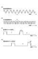
- FIG. 2 is a diagram showing waveforms of the direct modulation signal A, the external modulation signal B, the monitoring light gate signal C, and the electric signal gate signal D.
- FIG. 6A shows the waveform of the direct modulation signal A given from the signal generator 62 to the light source 41.
- FIG. 4B shows the waveform of the external modulation signal B given from the signal generator 63 to the intensity modulator 42.
- FIG. 4C shows the waveform of the monitoring light gate signal C supplied from the signal generator 64 to the monitoring light gate unit 44.
- FIG. 4D shows the waveform of the electric signal gate signal D supplied from the signal generator 65 to the electric signal gate unit 54.
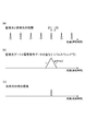
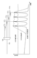
- FIG. 3 shows the correlation intensity between the reflected light (return monitoring light) and the reference light, the overlap (pulse window) of the monitoring light gate signal C and the electric signal gate signal D, and the detection sensitivity of the reflected light on the optical line. It is a figure shown in relation to position z.
- FIG. 4A shows the correlation intensity distribution between the reflected light (return monitoring light) and the reference light.
- FIG. 4B shows the overlap (pulse window) of the monitoring light gate signal C and the electrical signal gate signal D.
- FIG. 3C shows the detection sensitivity distribution of reflected light.
- FIG. 4 is a diagram showing a spectrum of an interference signal by reflected light from each of the positions z1 and z2 in the optical line shown in FIG.
- FIG. 6A shows the spectrum of an interference signal due to reflected light from the position z1 having a high correlation shown in FIG.
- FIG. 3B shows a spectrum of an interference signal caused by reflected light from the position z2 having a low correlation shown in FIG.
- the direct modulation signal A is a periodic signal having a period p, and is a signal for optical frequency modulating the output light from the light source 41.
- the period p defines the measurement position z in the optical line.
- the spectrum of the interference signal due to both lights has a frequency comparable to the line width of the monitoring light. It is localized in the band (see FIG. 4A).
- the correlation is low (in the case of the position z2 in FIG. 3A)
- the spectrum of the interference signal is spread over a frequency band approximately equal to the amplitude of the optical frequency modulation of the monitoring light (FIG. 4B). )reference). Therefore, reflected light from a specific measurement position can be selectively detected by performing optical frequency modulation with an amplitude larger than the line width of the monitoring light.
- the waveform of the direct modulation signal A is a sine wave in this embodiment, but may be various periodic waveforms such as a rectangular wave and a triangular wave.
- the spatial resolution is preferably 9 cm or less.
- the spatial resolution is preferably 9 cm or less.
- an optical fiber used as the second optical line in general, an optical fiber having an allowable bending radius of 15 mm is strengthened among single-mode optical fibers compliant with ITU-T G.652. is doing. By winding one turn at this allowable bending radius of 15 mm, a surplus length of 9 cm can be accommodated. Therefore, by setting the spatial resolution to 9 cm or less, the surplus length accommodation space can be minimized.
- the external modulation signal B is a periodic signal synchronized with the direct modulation signal A
- the output light from the light source 41 is synchronized with the direct modulation signal A by the intensity modulator 42.
- a signal for intensity modulation thereby, the spectrum of the light output from the intensity modulator 42 can be shaped.
- the reflected light detection sensitivity in OCDR is expressed as a function of distance, and this function of distance is known as a light wave coherence function.
- the light wave coherence function is preferably close to a delta function sequence.
- the position selectivity of the reflected light measurement by OCDR can be enhanced by shaping the spectrum by intensity modulation.
- the monitoring light gate signal C is a periodic signal having a pulse with a gate width w1 at a constant period T, and the monitoring light output from the monitoring light gate unit 44 is gated. This is a signal for selection only during the period of the pulse of width w1.
- the electric signal gate signal D is a periodic signal having a pulse with a gate width w2 at a constant period T, and is an electric signal output from the electric signal gate unit 54. Is a signal for selecting only during the pulse period of the gate width w2.
- the period T of the electric signal gate signal D is equal to the period T of the monitoring light gate signal C.
- the pulse center of the electrical signal gate signal D is delayed from the pulse center of the monitoring light gate signal C by a gate delay time d.
- the period p of the direct modulation signal A, the gate width w1 of the monitoring light gate signal C, and the gate width w2 of the electric signal gate signal D satisfy the relationship of the following expression (3).
- the gate delay time d is determined so that the correlation between the reflected light (return monitoring light) and the reference light has a peak at the center of the pulse window, a correlation peak that can exist in the pulse window. Is limited to one.
- the electric signal (current I1) to be performed is expressed by the following equation (4) when the proportionality coefficient is omitted.
- the first term of this equation is incoherent noise.
- ⁇ represents the attenuation coefficient of the in-phase component by balance detection. ⁇ is ideally zero, but actually takes a value of 10 ⁇ 5 or more, which causes noise.
- the second term is an interference signal.
- the non-interference noise is proportional to the light intensity, and has a DC component corresponding to the average power and a modulation component (period p) due to parasitic intensity modulation and external intensity modulation at the light source 41 as spectral components.
- a pulse is cut out by the electric signal gate signal D in the electric signal gate unit 54.
- the electrical signal (current I2) output from the electrical signal gate 54 is expressed by the following equation (5).
- F is an electric signal gate signal D and has a period T.
- the first term of this equation is incoherent noise and the second term is an interference signal.
- I2 ⁇ F (
- the incoherent noise of the first term of the equation (5) is a product of a function of frequency (1 / p) and a function of frequency (1 / T). / P + j / T).
- the pulse period is set so that the pulse repetition period T of each of the monitoring light gate signal C and the electric signal gate signal D is equal to an integral multiple of the modulation period p of the direct modulation signal A, incoherent noise is generated.
- the frequency is limited to i / T, where i is an integer. Therefore, a measurement result with less noise can be obtained by cutting out the component of the frequency band not including the frequency (i / T) by using the second filter 55 as the detection band.
- the operation of the optical line monitoring apparatus 14A according to the first embodiment will be described with reference to FIGS. 5 to 8, and the reflectance distribution along the optical line with high resolution by OTDR measurement and a plurality of OCDR measurements. A method for shortening the time required for the measurement will be described.
- FIG. 5 is a flowchart for explaining the operation of the optical line monitoring apparatus 14A according to the first embodiment.
- FIG. 6 is a diagram showing a simplified configuration of the optical line monitoring system 1A according to the first embodiment.
- 7 and 8 are diagrams illustrating calculation results of measurement waveforms when the reflectance distribution is measured in the optical line monitoring system 1A according to the first embodiment.
- the N value is 4, and the optical line monitoring system 1A includes four subscriber terminals 21 1 to 21 4 , and the connection ends of the subscriber terminals to the optical line are Assume that optical filters 22 1 to 22 4 are inserted.
- Distance from the optical line monitoring apparatus 14A to the optical filter 22 1 is 19004M
- distance from the optical line monitoring apparatus 14A to the optical filter 22 2 is 19005M
- distance from the optical line monitoring apparatus 14A to the optical filter 22 3 is 19006M
- distance from the optical line monitoring apparatus 14A to the optical filter 22 4 is assumed to be 19007M.
- the reflectance of each optical filter 22 n is ⁇ 5 dB.
- the reflectance distribution at this time is shown in FIG. 7A, and this distribution is measured by the optical line monitoring device 14A in the following procedure.
- step S1 measurement by OTDR is performed (step S1).
- pulsed monitoring light is output from the light source 71 of the OTDR measuring unit 16, and reflected light generated when the monitoring light propagates through the optical line is received by the photodetector 73 of the OTDR measuring unit 16, The intensity of the reflected light is measured as a function of time.
- the OTDR measurement result is converted into digital data by the AD converter 74, acquired by the control unit 75, and further acquired by the control unit 17.
- the length of a typical optical line is about 20 km or less, and the speed of light in the optical line is about 2 ⁇ 10 8 m / s. Therefore, the time until the monitoring light is reflected and returned is at most 100 ⁇ s. It is. Therefore, it is possible to perform OTDR measurement in a short time.
- the spatial resolution of OTDR has a practical lower limit of about 2 m due to a decrease in the S / N ratio when the pulse width is reduced. As shown in FIG. 7B, the OTDR measurement result at this time cannot be individually identified as four optical filters with an interval of 1 m, and is measured as one wide reflection peak.
- threshold processing is performed on the above OTDR measurement result (step S2).
- a distance range R1 in which the reflected light power is equal to or greater than the threshold is extracted.
- the threshold is set between the power at the reflection peak and the reflected light power due to Rayleigh scattering from the optical line.
- the measurement range R1 is a range of 11 m ranging from 19000 m to 19011 m.
- the first OCDR measurement is performed using the distance range R1 as the measurement range (step S3).
- the spatial resolution is 20 cm.
- FIG. 7C shows a measurement result obtained by connecting the result of the first OCDR measurement in the measurement range R1 and the result of the OTDR measurement in a range other than the measurement range R1.
- four optical filters with 1 m spacing are individually identified as four reflection peaks.
- threshold processing is performed on the first OCDR measurement result (step S4).
- a distance range R2 where the reflected light power is equal to or greater than the threshold is extracted.
- the second OCDR measurement is performed using the distance range R2 as the measurement range (step S5).
- the spatial resolution is 4 cm.
- a measurement result obtained by connecting the result of the second OCDR measurement in the measurement range R2 and the result of the first OCDR measurement in the range other than the measurement range R2 (including the result of the OTDR measurement) is shown in FIG. ).
- a peak detection process is performed on the second OCDR measurement result (step S6).
- the positions of the four optical filters are recognized, and the data of the positions and intensities (peak values of reflected light power) of the discrete reflection points are obtained. This data is shown as a plot in FIG.
- the position and intensity data of the discrete reflection points stored in the storage device 18 and the impulse response of the first OCDR measurement are convolutionally calculated, and the contribution of the impulse response of the first OCDR measurement to the measurement result Is calculated (step S7).
- the impulse response is a measurement result obtained when there is only one reflection point.
- the four impulse responses convolved at each of the four discrete reflection points are shown by dotted lines in FIG.
- the contribution of the impulse response to the first OCDR measurement is obtained by adding these impulse responses in a range other than the measurement range R2. This is indicated by a solid line in FIG.
- a reflectance distribution in which the impulse response of the first OCDR measurement is corrected is obtained.
- the corrected reflectance distribution is shown in FIG.
- Step S8 the position and intensity data of the discrete reflection points stored in the storage device 18 and the impulse response of the OTDR measurement are convolutionally calculated, and the contribution of the impulse response of the OTDR measurement to the measurement result is calculated (Ste S8).
- the four impulse responses convolved with each of the four discrete reflection points are shown by dotted lines in FIG.
- the contribution of the impulse response to the first OCDR measurement is obtained by adding these impulse responses in a range other than the measurement range R2. This is shown by the solid line in FIG.
- the contribution due to the impulse response is subtracted from the reflectance distribution in which the impulse response of the first OCDR measurement is corrected (FIG. 8B), thereby obtaining a reflectance distribution in which the impulse response of the OTDR measurement is corrected.
- the corrected reflectance distribution is shown in FIG. As shown in FIG. 8D, a measurement result that closely matches the reflectance distribution to be measured (FIG. 7A) is obtained.
- discontinuity of the measurement result due to the impulse response occurs at the boundary of the measurement range.
- a measurement result with reduced discontinuity can be obtained as shown in FIG.
- Discontinuities in the reflectance distribution measurement results are often difficult to distinguish from contributions to the measurement results, such as reflections in the optical line and optical losses, so by reducing discontinuities, Feature point detection can be reduced.
- an impulse response may be obtained by intentionally providing a reflection point in the optical line monitoring apparatus or in the optical line and measuring the reflection point.
- a discrete reflection point can be obtained over a wide distance range by combining the OTDR measurement (resolution 2 m), the first OCDR measurement (resolution 20 cm), and the second OCDR measurement (resolution 4 cm). Can be detected in a short time with high spatial resolution. If the distance range of about 20 km is measured without omission using the OCDR with a resolution of 4 cm as shown above, the number of OCDR measurement points is 500,000. In a typical OCDR measurement, about 1 ms / point is required, and thus the measurement time is 500 seconds.
- the measurement time by OTDR is 100 ⁇ s
- the measurement time is shortened to 137 ms.
- FIG. 9 is a diagram illustrating a configuration of an optical line monitoring system 1B including the optical line monitoring apparatus 14B according to the second embodiment.
- the optical line monitoring system 1B according to the second embodiment shown in FIG. 9 replaces the station building 10A with the station building 10B. It differs in the point provided, and it differs in that the station is provided with an optical line monitoring device 14B instead of the optical line monitoring device 14A.
- the optical line monitoring device 14B in FIG. 9 includes an OCDR / OTDR measurement unit 15B instead of the OCDR measurement unit 15 and the OTDR measurement unit 16. It ’s different. 1 is different from the configuration of the OCDR measurement unit 15 in FIG. 1 in that the OCDR / OTDR measurement unit 15B in FIG. 9 includes an optical switch 66 and an AD converter 67.
- the optical switch 66 is provided between the optical branching device 43 and the polarization modulator 46, and passes / blocks the light branched from the optical branching device 43 and output.
- the AD converter 67 converts the electric signal (analog signal) output from the balance detector 52 into a digital signal and outputs the digital signal to the control unit 61.
- the OCDR / OTDR measurement unit 15B can perform both OCDR measurement and OTDR measurement.
- the optical switch 66 is opened.
- the other components of the OCDR / OTDR measurement unit 15B operate in the same manner as the OCDR measurement unit 15 in FIG. 1 to realize OCDR measurement.
- the optical switch 66 When the OCDR / OTDR measurement unit 15B performs OTDR measurement, the optical switch 66 is turned off, and the light branched and output from the optical splitter 43 is not input to the balance detector 52.
- the signal generator 62 outputs a pulse signal, and the light source 41 to which the pulse signal is input outputs pulsed monitoring light.
- the light intensity modulator 42 and the monitoring light gate unit 44 are opened, and the pulsed monitoring light output from the light source 41 passes through the light intensity modulator 42 and the monitoring light gate unit 44 as they are.
- pulsed monitoring light may be generated by outputting continuous light from the light source 41 and modulating the light intensity by the light intensity modulator 42 or the monitoring light gate unit 44.
- frequency modulation in the light source 41 and diffusing the optical spectrum it is possible to suppress the occurrence of stimulated Brillouin scattering in the optical line, and to send higher-power monitoring light to the optical line. Become.
- the SN ratio of the measurement is improved, the measurement distance is extended, and the allowable optical line loss can be increased.
- the monitoring light is transmitted to the PON system (first optical line 32, optical branching unit 20, second optical line 33 n , optical filter 22 n ) to be measured via the optical circulator 45 and the optical coupler 12, and measured.
- the reflected light generated in the object reaches the balance detector 52 through the optical coupler 12 and the optical circulator 45.
- the balance detector 52 performs an unbalance operation and outputs an electric signal proportional to the reflected light power.
- the electrical signal output from the balance detector 52 is branched into two, one being output to the AD converter 57 via the first filter 53 and the other being output to the AD converter 67. Among these, the output from the AD converter 67 is read by the control unit 61 and stored as an OTDR measurement result.
- the OCDR measurement result and the OTDR measurement result acquired by the OCDR / OTDR measurement unit 15B as described above are processed in the control unit 17 in the same manner as in the first embodiment.
- the light source unit and the detection unit in the OTDR measurement and the OCDR measurement are shared.
- incompatibility between the OTDR measurement result and the OCDR measurement result caused by the variation in the light source wavelength and the variation in the sensitivity of the detection unit can be reduced as compared with the case where they are not shared.
- Such inconsistencies cannot be removed by the impulse response correction processing described in the first embodiment, and cause discontinuities in the measurement results.
- by sharing the light source unit and the detection unit as in the present embodiment such discontinuity can be reduced, and erroneous detection of feature points in the optical line can be reduced.
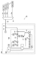
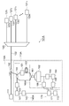
- FIG. 10 is a configuration diagram of the optical communication system 101A and the light reflection measuring apparatus 113A according to the third embodiment.
- a station-side terminal 111 and N subscriber terminals 121 1 to 121 N provided in a station 110A are optically connected to each other via an optical branching unit 120 via an optical fiber line. And performs optical communication between the station-side terminal 111 and each subscriber terminal 121 n .
- N is an integer of 2 or more
- n is an integer of 1 or more and N or less.
- Such a form of the optical communication system 101A is called a PON (Passive Optical Network).
- the number of branches N is typically 4 to 32.
- the station 110A is provided with an optical coupler 112 and a light reflection measuring device 113A.
- the station side terminal 111 and the optical coupler 112 are optically connected by an optical fiber line 131.
- the optical coupler 112 and the optical branching device 120 are optically connected by an optical fiber line 132.
- the optical branching device 120 and each subscriber terminal 121 n are optically connected by an optical fiber line 133 n .
- the optical coupler 112 is also optically connected with a light reflection measuring device 113A.
- the light reflection measuring device 113A can perform both OCDR measurement and OTDR measurement, and outputs a combination of the OCDR measurement result and the OTDR measurement result.
- the light reflection measurement device 113A includes a light source unit 140A, a measurement unit 160A, and a processing unit 170, and further includes an optical modulator 151 and an optical delay line 152.
- the light source unit 140A selects either the first monitoring light or the second monitoring light having a comb-like light wave coherence function whose optical frequency is modulated and outputs the selected light to the optical coupler 112. In addition, the light source unit 140A branches a part of the first monitoring light and outputs it as a reference light to the optical modulator 151. The first monitoring light and the reference light are used for OCDR measurement, and the second monitoring light is used for OTDR measurement.
- the light source unit 140 ⁇ / b> A includes a light source 141, a signal generator 142, an optical modulator 143, and an optical coupler 144.
- the light source 141 included in the light source unit 140A can modulate the optical frequency of output light, and is, for example, a semiconductor DFB laser light source or a semiconductor laser light source with an external resonator.
- the light source 141 outputs continuous light.
- the signal generator 142 outputs a modulation signal for modulating the optical frequency of the continuous light output from the light source 141, and provides the modulation signal to the light source 141.
- the light modulator 143 receives light output from the light source 141, modulates the light as necessary, and outputs the modulated light.
- the optical coupler 144 bifurcates the light output from the optical modulator 143, outputs one branched light to the optical coupler 112, and outputs the other branched light to the optical modulator 151.
- the measurement unit 160A acquires the OCDR measurement result based on the reflected light generated when the first monitoring light output from the light source unit 140A propagates through the measurement target and the reference light output from the light source unit 140A. In addition, the measurement unit 160A acquires the OTDR measurement result based on the reflected light generated when the second monitoring light output from the light source unit 140A propagates through the measurement target.
- the measurement unit 160A includes an optical coupler 161, a balance detector 162, a filter 163, an RF detector 164, an AD converter 165, and an AD converter 166.
- the optical coupler 161 included in the measurement unit 160A inputs the light output from the optical coupler 144, and also inputs the light when the light is output from the optical delay line 152.
- the light is output to the balance detector 162.
- the balance detector 162 receives and detects the light output from the optical coupler 161, and outputs an electrical signal representing the detection result to the filter 163 or the AD converter 166.
- the filter 163 receives the electrical signal output from the balance detector 162, removes noise components included in the electrical signal, and outputs the electrical signal after the removal to the RF detector 164.
- the RF detector 164 included in the measurement unit 160A receives the electrical signal output from the filter 163, converts the electrical signal into an electrical signal corresponding to the magnitude of the interference component, and outputs the electrical signal to the AD converter 165.
- the AD converter 165 receives the electrical signal output from the RF detector 164, converts the electrical signal (analog signal) into a digital signal, and outputs the digital signal (OCDR measurement result) to the treatment unit 170.
- the AD converter 166 receives the electrical signal output from the balance detector 162, converts the electrical signal (analog signal) into a digital signal, and converts the digital signal (OTDR measurement result) to the treatment unit 170. Output.
- AD converter 166 is not used in the OCDR measurement. Further, the filter 163, the RF detector 164, and the AD converter 165 are not used in the OTDR measurement.
- the processing unit 170 outputs a combination of the OCDR measurement result and the OTDR measurement result acquired by the measurement unit 160A.
- the processing unit 170 performs a predetermined calculation based on the OCDR measurement result and the OTDR measurement result, and outputs the calculation result.
- the processing unit 170 includes a control unit 171 and a storage unit 172.
- the control unit 171 included in the processing unit 170 controls the operation of the light source unit 140A.
- the control unit 171 receives the digital signal (OCDR measurement result) output from the AD converter 165 and the digital signal (OTDR measurement result) output from the AD converter 166, and performs these OCDR measurements.
- the result and the OTDR measurement result are stored in the storage unit 172.
- the storage unit 172 stores a pulse time waveform of the second monitoring light in advance. Then, the control unit 171 performs a predetermined calculation based on the OCDR measurement result, the OTDR measurement result, and the pulse time waveform of the second monitoring light, and outputs the calculation result.
- the light source unit 140A outputs the first monitoring light having a comb-like lightwave coherence function with the optical frequency modulated.
- the continuous light output from the light source 141 is modulated in optical frequency by the signal generator 142 and has a comb-like optical wave coherence function.
- the optical frequencies are sequentially set to f 0 , f 0 + f s , f 0 ⁇ f s , f 0 + 2f s , f 0 ⁇ 2f s , f 0 + 3f s , f 0 ⁇ 3f s ,. ..
- the modulated light is used as the first monitoring light.
- light whose optical frequency is modulated in a sine wave shape at the modulation frequency f s is used as the first monitoring light.
- the optical coherence function of the first monitoring light whose optical frequency is modulated in this way has a peak (coherence peak) having a shape similar to the delta function shape when f s ⁇ is an integer. That is, these first monitoring lights have a comb-like light wave coherence function. As f s changes, the position of the coherence peak also changes.
- the optical modulator 143 preferably modulates the intensity of the continuous light output from the light source 141 in synchronization with the optical frequency modulation, and outputs the intensity-modulated light as the first monitoring light.
- Such first monitoring light is one in which the side lobe of the lightwave coherence function is suppressed.
- the optical coupler 144 outputs the first monitoring light output from the optical modulator 143 to the optical coupler 112 and branches a part of the first monitoring light to output to the optical modulator 151 as reference light. To do.
- the first monitoring light output from the optical coupler 144 to the optical coupler 112 propagates to the subscriber terminal 121 n via the optical fiber line 132, the optical branching unit 120, and the optical fiber line 133 n .
- the first monitoring light propagates through the measurement object (optical fiber line 132, optical branching device 120, optical fiber line 133 n , subscriber terminal 121 n )
- Fresnel reflected light is reflected at discrete reflection points on the measurement object.
- Rayleigh scattered light occurs in the section between the discrete reflection points.
- the reference light output from the optical coupler 144 to the optical modulator 151 is input to the optical coupler 161 via the optical modulator 151 and the optical delay line 152.
- the optical modulator 151 receives the reference light output from the optical coupler 144, and gates the reference light at a predetermined timing as necessary, thereby measuring the position to be measured in the object to be measured in the OCDR measurement. To decide.
- the optical delay line 152 reduces the optical path length difference between the reflected light of the first monitoring light input to the optical coupler 161 and the reference light by delaying the reference light output from the optical modulator 151. Thus, noise generated by the phase fluctuation of the light output from the light source 141 is reduced.
- the optical modulator 151 may perform polarization modulation of the reference light, shift the optical frequency of the reference light, or may apply a plurality of the reference light, in addition to gating the reference light. May be processed.
- polarization-modulating the reference light and averaging the OCDR measurement results in a plurality of polarization states the influence of the polarization fluctuations of the first monitoring light and the reference light can be reduced.
- shifting the optical frequency of the reference light so that the reflected light of the first monitoring light is subjected to heterodyne detection, noise due to intensity fluctuation of the first monitoring light can be reduced.
- the optical coupler 161 combines the reflected light of the first monitoring light output from the optical coupler 144 and the reference light output from the optical delay line 152, and outputs these to the balance detector 162.
- the balance detector 162 receives the reflected light and the reference light, performs balance detection, and outputs an electric signal corresponding to the interference component of the electric field of each of the reflected light and the reference light to the filter 163.
- the filter 163 receives the electrical signal output from the balance detector 162, removes noise components included in the electrical signal, and outputs the electrical signal after the removal to the RF detector 164.
- the RF detector 164 receives the electrical signal output from the filter 163, converts the electrical signal into an electrical signal corresponding to the magnitude of the interference component, and outputs the electrical signal to the AD converter 165.
- the AD converter 165 receives the electrical signal output from the RF detector 164, converts the electrical signal into a digital signal, and outputs the digital signal to the control unit 171.
- the control unit 171 receives the digital signal output from the AD converter 165 and causes the storage unit 172 to store the digital signal. The value of this digital signal represents the reflectance at the measurement position in the measurement object.
- the position of the coherence peak (that is, the position to be measured in the measurement object) is changed by changing the parameter f s at the time of optical frequency modulation in the light source 141 according to control by the control unit 171, and Similarly, the storage unit 172 stores a digital signal representing the reflectance at the measurement position on the measurement object.
- the OCDR measurement result is obtained by scanning the position of the coherence peak (that is, the position to be measured in the measurement object).
- the light source unit 140A outputs pulsed second monitoring light.
- the optical modulator 143 modulates the intensity of the continuous light output from the light source 141 and outputs it as pulsed second monitoring light.
- the light source 141 modulates the optical frequency in accordance with the modulation signal output from the signal generator 142 and outputs the spectrum-spread continuous light.
- the optical coupler 144 outputs the second monitoring light output from the optical modulator 143 to the optical coupler 112 and branches a part of the second monitoring light to output it to the optical modulator 151.
- the light output to the optical modulator 151 is blocked by the optical modulator 151.
- the second monitoring light output from the optical coupler 144 to the optical coupler 112 propagates to the subscriber terminal 121 n via the optical fiber line 132, the optical branching unit 120, and the optical fiber line 133 n .
- the second monitoring light propagates through the measurement object (optical fiber line 132, optical branching device 120, optical fiber line 133 n , subscriber terminal 121 n )
- Fresnel reflected light is reflected at discrete reflection points on the measurement object.
- Rayleigh scattered light occurs in the section between the discrete reflection points.
- the optical coupler 161 receives the reflected light of the second monitoring light output from the optical coupler 144 and outputs it to the balance detector 162.
- the balance detector 162 performs an unbalance operation, inputs light output from the optical coupler 161, and outputs an electrical signal corresponding to the input optical power to the AD converter 166.
- This electrical signal as a function of time represents the reflectance distribution in the measurement object.
- the AD converter 166 receives the electric signal output from the balance detector 162, converts the electric signal into a digital signal at regular time intervals, and outputs the digital signal to the control unit 171.
- the control unit 171 receives the digital signal output from the AD converter 166 and causes the storage unit 172 to store the digital signal. In this way, an OTDR measurement result is obtained.
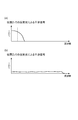
- FIG. 11 is a diagram schematically illustrating the OCDR measurement result, the OTDR measurement result, and the processing result of the processing unit 170.
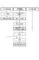
- FIG. 12 is a diagram illustrating a processing flow of the processing unit 170.
- the control unit 171 included in the processing unit 170 includes the OCDR measurement result and the OTDR measurement result obtained as described above and stored in the storage unit 172, and the second monitoring light stored in advance in the storage unit 172.
- the following processing is performed using the pulse time waveform.
- the position of the discrete reflection point (for example, the connection point between the optical fiber line 133 n and the subscriber terminal 121 n ) can be obtained with high spatial resolution.
- coherence noise due to the side lobe of the light wave coherence function is observed, so information in the section cannot be obtained.
- Rayleigh scattered light is observed in the section between the discrete reflection points, but in the vicinity of these reflection points, the reflection point position and the pulse time waveform of the second monitoring light are convoluted. A broad peak is observed.
- the processing unit 170 of the light reflection measurement apparatus 113A performs the OCDR measurement result, the OTDR measurement result, and the pulse of the second monitoring light.
- the processing shown in FIG. 12 using the time waveform, a high-resolution reflection point measurement result including the Rayleigh scattered light measurement as shown in FIG. 11 is obtained.
- control unit 171 included in the processing unit 170 uses the OCDR measurement result stored in the storage unit 172 to detect the peak position by performing threshold processing of the OCDR measurement result at a predetermined level higher than the coherence noise. Thus, a list of positions of discrete reflection points in the measurement object is obtained.
- control unit 171 uses information such as the pulse time waveform of the second monitoring light stored in the storage unit 172 and the longitudinal distribution of the chromatic dispersion and polarization mode dispersion of the measurement object, A pulse time waveform of the second monitoring light at each position due to the pulse spread when the second monitoring light propagates through the measurement object is obtained.
- control unit 171 performs a convolution operation on the already obtained position list of the discrete reflection points and the pulse time waveform of the second monitoring light at each position, thereby performing OTDR due to the reflection of the second monitoring light at the discrete reflection points. Obtain the degree of contribution to the measurement results.
- control part 171 correct
- the light reflection measuring apparatus 113A By performing such processing by the processing unit 170, the light reflection measuring apparatus 113A according to the present embodiment can detect Rayleigh scattered light and discrete reflected light generated in the measurement object with high accuracy, A measurement result of the reflectance distribution with high resolution can be obtained.
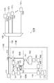
- FIG. 13 is a configuration diagram of the optical communication system 101B and the light reflection measuring apparatus 113B according to the fourth embodiment.
- the optical communication system 101B according to the fourth embodiment shown in FIG. 13 has a station 110B instead of the station 110A. It differs in the point provided, and it differs in the point provided with the light reflection measuring device 113B instead of the light reflection measuring device 113A.
- the light reflection measuring device 113B in FIG. 13 is different in that it includes a light source unit 140B instead of the light source unit 140A, and instead of the measurement unit 160A.
- the difference is that the measurement unit 160B is included, and that the optical circulator 153 is further included.
- the light source unit 140B includes a light source 141, a signal generator 142, an optical modulator 143, and an optical coupler 144.
- the optical coupler 144 is provided between the light source 141 and the optical modulator 143, divides each of the first monitoring light and the second monitoring light output from the light source 141 into two, and one of the branched lights is an optical modulator. The other branched light is output to the optical modulator 151.
- the optical modulator 143 receives the light output from the optical coupler 144, modulates the light, and outputs the modulated light to the optical circulator 153.
- the optical circulator 153 receives the light output from the optical modulator 143 and outputs the input light to the optical coupler 112.
- the optical circulator 153 receives the light output from the optical coupler 112 and outputs the input light to the optical coupler 161.
- the measurement unit 160B includes an optical coupler 161, a balance detector 162, a filter 163, an RF detector 164, and an AD converter 165.
- the optical coupler 161 receives the light output from the optical circulator 153 and also receives the light output from the optical delay line 152, and outputs these lights to the balance detector 162.
- the first monitoring light output from the light source 141 passes through the optical coupler 144, the optical modulator 143, the optical circulator 153, and the optical coupler 112, and then the measurement object (optical fiber line 132, optical branching device). 120, optical fiber line 133 n , subscriber terminal 121 n ). Reflected light (Fresnel reflected light, Rayleigh scattered light) generated during this propagation is input to the optical coupler 161 through the optical coupler 112 and the optical circulator 153. Further, a part of the first monitoring light output from the light source 141 is branched by the optical coupler 144 to become reference light. The reference light is input to the optical coupler 161 through the optical modulator 151 and the optical delay line 152. In the measurement unit 160B and the processing unit 170, the same operation as that in the third embodiment is performed, and an OCDR measurement result is obtained.
- the second monitoring light output from the light source 141 propagates through the measurement object through the optical coupler 144, the optical modulator 143, the optical circulator 153, and the optical coupler 112.
- Reflected light (Fresnel reflected light, Rayleigh scattered light) generated during this propagation is input to the optical coupler 161 through the optical coupler 112 and the optical circulator 153.
- a part of the second monitoring light output from the light source 141 is branched by the optical coupler 144 to become reference light.
- the reference light is input to the optical coupler 161 through the optical modulator 151 and the optical delay line 152.
- the balance detector 162 performs a balance detection operation even in the case of OTDR measurement.
- the optical frequency of the reference light is shifted by the optical modulator 151, and the second monitoring light is heterodyne detected by the balance detector 162.
- C-OTDR coherent OTDR
- the processing unit 170 performs the same processing as in the third embodiment.
- a high-resolution reflectance distribution measurement result as shown in FIG. 11 is obtained.
- the shot noise limit can be measured by using a reference light having sufficiently high power in C-OTDR, it should also be used for a PON system having a high insertion loss in the optical branching unit 120 such as a 32-branch system. Can do.
- the light reflection measuring device (1) selects and outputs either the first monitoring light or the pulsed second monitoring light having a comb-like light wave coherence function with the fluorescence frequency modulated, and the first A light source unit that branches a part of one monitoring light and outputs it as a reference light; and (2) a reflected light generated when the first monitoring light output from the light source unit propagates through the measurement object and the light source unit.
- a measurement unit that obtains an OCDR measurement result based on the reference light to be obtained, and obtains an OTDR measurement result based on the reflected light generated when the second monitoring light output from the light source unit propagates through the measurement object; 3) A processing unit that outputs a combination of the OCDR measurement result and the OTDR measurement result acquired by the measurement unit.
- the OCDR measurement result and the OTDR measurement result are combined and output, so that the discrete reflection point on the measurement object is detected with a high spatial resolution, and the interval between the discrete reflection points on the measurement object. Can also be measured.
- the processing unit obtains the position of the discrete reflection point on the measurement object based on the OCDR measurement result, and uses the obtained position of the discrete reflection point and the pulse time waveform of the second monitoring light. Based on this, the degree of contribution to the OTDR measurement result due to the reflection of the second monitoring light at the discrete reflection point is obtained, the OTDR measurement result is corrected based on the obtained degree of contribution, and the correction result is output. Is preferred. By performing such processing, the state near the discrete reflection point in the measurement object is measured, and information on the section between the discrete reflection point and the discrete reflection point can be unified.
- the optical communication system is an optical communication system that performs optical communication between a station-side terminal and a subscriber terminal that are optically connected to each other via an optical fiber line, and is provided in the middle of the optical fiber line.
- a coupler and the above-described light reflection measuring device optically connected to the optical coupler, wherein the first monitoring light or the second monitoring light selectively output from the light reflection measuring device is supplied to the optical coupler.
- the reflected light generated when the first monitoring light or the second monitoring light propagates through the optical fiber line is input to the light reflection measuring device via the optical coupler.
- a station side terminal and a plurality of subscriber terminals are optically connected via an optical branching unit, and an optical fiber line between the station side terminal and the optical branching unit. It is preferable that an optical coupler is provided in the middle. As described above, by using the above-described light reflection measuring apparatus in the optical communication system, it is possible to specify the location of the failure that occurs in the subscriber terminal or the optical fiber line.
- the optical fiber length from the optical branching device to each of the plurality of subscriber terminals is different for each subscriber terminal.
- the subscriber terminals can be individually distinguished.
- the present invention is not limited to the above embodiment, and various modifications are possible.
- the wavelength of the first monitoring light or the second monitoring light is preferably the 1.58 to 1.65 ⁇ m band.
- the optical coupler 112 is preferably a wavelength multiplexer, and the insertion loss of signal light and monitoring light is minimized.
- the second monitoring light used for OTDR measurement may be generated by directly modulating the light source 141.
- the lengths of the optical fiber lines 133 1 to 133 N are preferably different from each other, as schematically shown in FIGS.
- the difference in length of each optical fiber line 133 n is larger than the typical resolution of the OCDR measurement (for example, 50 cm or more), discrete reflection occurring at the connection point between the subscriber terminal 121 n and the optical fiber line 133 n.
- the typical resolution of the OCDR measurement for example, 50 cm or more
- insertion of a reflective marker element having discrete reflection points formed at different intervals for each subscriber terminal between the subscriber terminal 121 n and the optical fiber line 133 n can also be used as the terminal discriminating means. it can.
- the information on the distance from each subscriber terminal to the station building is acquired by the measurement at the time of or after the construction of the optical communication system, and stored in the storage unit 172.
- the OCDR measurement range may be limited to the vicinity of the stored distance to the subscriber terminal. Thereby, it is possible to monitor in a short time whether or not the optical connection between each subscriber terminal and the station building is maintained.
- SYMBOLS 1A, 1B Optical line monitoring system, 10A, 10B ... Station, 11 ... Station side terminal, 12 ... Optical coupler, 13 ... Optical switch, 14A, 14B ... Optical line monitoring apparatus, 15 ... OCDR measurement part, 15B ... OCDR / OTDR measurement unit, 16 ... OTDR measurement unit, 17 ... control unit, 18 ... storage device, 20 ... optical branching unit, 21 1 to 21 N ... subscriber terminal, 22 1 to 22 N ... optical filter, 31, 32 , 33 1 to 33 N ... optical fiber line, 41 ... light source, 42 ... intensity modulator, 43 ... optical splitter, 44 ... monitoring light gate unit, 45 ...
- optical circulator 46 ... polarization modulator, 47 ... delayed light Fiber: 51 ... Optical coupler, 52 ... Balance detector, 53 ... First filter, 54 ... Electric signal gate unit, 55 ... Second filter, 56 ... RF detector, 57 ... AD converter, 61 ... Control unit, 62-65 ... Generator, 66 ... Optical switch, 67 ... AD converter, 71 ... Light source, 72 ... Optical circulator, 73 ... Optical detector, 74 ... AD converter, 75 ... Control unit, 76 ... Signal generator, 101A, 101B ... Optical communication system, 110A, 110B ... station, 111 ... station side terminal, 112 ... optical coupler, 113A, 113B ...
- light reflection measuring device 120 ... optical splitter, 121 1 to 121 N ... subscriber terminal, 131, 132, 133 1 to 133 N : optical fiber line, 140A, 140B: light source unit, 141: light source, 142: signal generator, 143: optical modulator, 144: optical coupler, 151: optical modulator, 152: light Delay line, 153... Optical circulator, 160A, 160B... Measuring unit, 161... Optical coupler, 162... Balance detector, 163 ... Filter, 164 ... RF detector, 165. D converter, 166 ... AD converter, 170 ... processing unit, 171 ... control unit, 172 ... storage unit.
Abstract
Description
Claims (6)
- OTDRまたはOCDRにより、第1監視光を光線路に伝搬させ、その第1監視光の伝搬の際に生じる第1反射光を受光して、前記光線路における光伝搬方向に沿った反射率分布を第1測定結果として取得する第1測定手段と、
OCDRにより、第2監視光を前記光線路に伝搬させ、その第2監視光の伝搬の際に生じる第2反射光を受光して、前記光線路における光伝搬方向に沿った反射率分布を第2測定結果として取得する第2測定手段と、
前記第1測定手段による前記第1測定結果の取得を第1空間分解能で行わせた後、その第1測定結果に基づいて決定される前記光線路の一部範囲について前記第2測定手段による前記第2測定結果の取得を前記第1空間分解能より小さい第2空間分解能で行わせる制御部と、
を備えることを特徴とする光線路監視装置。 - 前記制御部が、
前記第2測定結果に基づいて前記光線路における離散反射点の位置を求め、
この求めた離散反射点の位置と前記第1空間分解能とに基づいて、前記離散反射点での反射による前記第1測定結果への寄与の程度を求め、
この求めた寄与の程度に基づいて前記第1測定結果を補正して、その補正結果を出力する、
ことを特徴とする請求項1に記載の光線路監視装置。 - 前記第1測定手段において前記第1監視光を出力する光源部と、前記第2測定手段において前記第2監視光を出力する光源部とが、共通の部品を含み、
前記第1測定手段において前記第1反射光を受光する検出部と、前記第2測定手段において前記第2反射光を受光する検出部とが、共通の部品を含む、
ことを特徴とする請求項1に記載の光線路監視装置。 - 光線路により互いに光学的に接続された局側端末と加入者端末との間で光通信を行う光通信システムを監視するシステムであって、
前記光線路の途中に設けられた光結合器と、この光結合器に光学的に接続された請求項1~3の何れか1項に記載の光線路監視装置と、を備え、
前記光線路監視装置から選択的に出力される前記第1監視光または前記第2監視光を、前記光結合器を経て前記光線路に伝搬させ、
前記第1反射光または前記第2反射光を、前記光結合器を経て前記光線路監視装置に入力させる、
ことを特徴とする光線路監視システム。 - 前記局側端末と複数の加入者端末とが光分岐器を介して光学的に接続されており、
前記局側端末と前記光分岐器との間の光線路の途中に前記光結合器が設けられている、
ことを特徴とする請求項4に記載の光線路監視システム。 - 前記複数の加入者端末それぞれが、前記第1監視光および前記第2監視光を波長選択的に反射する反射フィルタを含む、ことを特徴とする請求項5に記載の光線路監視システム。
Priority Applications (4)
| Application Number | Priority Date | Filing Date | Title |
|---|---|---|---|
| KR1020107028444A KR101536375B1 (ko) | 2008-06-02 | 2009-05-25 | 광 선로 감시 장치 및 광 선로 감시 시스템 |
| EP09758230.8A EP2284514B1 (en) | 2008-06-02 | 2009-05-25 | Beam path monitoring device, and beam path monitoring system |
| US12/995,252 US8654320B2 (en) | 2008-06-02 | 2009-05-25 | Beam Path Monitoring Device and Beam Path Monitoring System |
| CN2009801204408A CN102047092B (zh) | 2008-06-02 | 2009-05-25 | 光线路监视装置及光线路监视系统 |
Applications Claiming Priority (4)
| Application Number | Priority Date | Filing Date | Title |
|---|---|---|---|
| JP2008144903A JP2009293950A (ja) | 2008-06-02 | 2008-06-02 | 光反射測定装置 |
| JP2008-144903 | 2008-06-02 | ||
| JP2009021442A JP5359326B2 (ja) | 2009-02-02 | 2009-02-02 | 光線路監視装置および光線路監視システム |
| JP2009-021442 | 2009-02-02 |
Publications (1)
| Publication Number | Publication Date |
|---|---|
| WO2009147963A1 true WO2009147963A1 (ja) | 2009-12-10 |
Family
ID=41398039
Family Applications (1)
| Application Number | Title | Priority Date | Filing Date |
|---|---|---|---|
| PCT/JP2009/059498 WO2009147963A1 (ja) | 2008-06-02 | 2009-05-25 | 光線路監視装置および光線路監視システム |
Country Status (7)
| Country | Link |
|---|---|
| US (1) | US8654320B2 (ja) |
| EP (1) | EP2284514B1 (ja) |
| KR (1) | KR101536375B1 (ja) |
| CN (1) | CN102047092B (ja) |
| PT (1) | PT2284514E (ja) |
| TW (1) | TW201011271A (ja) |
| WO (1) | WO2009147963A1 (ja) |
Cited By (1)
| Publication number | Priority date | Publication date | Assignee | Title |
|---|---|---|---|---|
| CN110140037A (zh) * | 2016-12-28 | 2019-08-16 | 艾迪量子股份公司 | 用于光纤的测量设备和方法 |
Families Citing this family (37)
| Publication number | Priority date | Publication date | Assignee | Title |
|---|---|---|---|---|
| US8213002B2 (en) * | 2009-03-04 | 2012-07-03 | Fluke Corporation | PON tester |
| WO2012087205A1 (en) * | 2010-12-22 | 2012-06-28 | Telefonaktiebolaget Lm Ericsson (Publ) | Otdr trace analysis in pon systems |
| TWI407653B (zh) * | 2010-12-30 | 2013-09-01 | Univ Nat Taiwan Science Tech | 環型光纖雷射系統及其操作方法 |
| US20120219285A1 (en) * | 2011-02-28 | 2012-08-30 | David Jimmy Dahan | In-band optical signal to noise ratio monitoring technique |
| US9118412B2 (en) | 2011-09-27 | 2015-08-25 | Broadcom Corporation | System and method for performing in-band reflection analysis in a passive optical network |
| CN102445330B (zh) * | 2011-09-29 | 2014-06-25 | 四川汇源塑料光纤有限公司 | 塑料光纤生产在线监测损耗的方法 |
| TWI458953B (zh) * | 2011-12-29 | 2014-11-01 | Chunghwa Telecom Co Ltd | 光纖水感知系統與方法 |
| US8805183B2 (en) | 2012-02-08 | 2014-08-12 | Broadcom Corporation | Optical line terminal (OLT) and method therefore for performing in-band and out-band OTDR measurements |
| US9118982B2 (en) | 2012-02-08 | 2015-08-25 | Broadcom Corporation | Optical line terminal (OLT) optical module adapted to perform optical unit network (ONU) functionality |
| WO2013176505A1 (en) * | 2012-05-25 | 2013-11-28 | Ls Cable & System Ltd. | Optical line monitoring device, optical line monitoring system including the optical line monitoring device, and method of controlling the optical line monitoring system |
| WO2014041350A1 (en) * | 2012-09-13 | 2014-03-20 | Mbda Uk Limited | Room occupancy sensing apparatus and method |
| KR20140093515A (ko) | 2013-01-18 | 2014-07-28 | 한국전자통신연구원 | 광 링크 장애 감시장치 및 그 방법 |
| CN103973362A (zh) * | 2013-02-06 | 2014-08-06 | 中兴通讯股份有限公司 | 设置otdr测试参数集的方法及装置 |
| CN103297126B (zh) * | 2013-06-07 | 2016-06-22 | 广西师范大学 | 基于光学标记法的pon线路故障监测方法及其装置 |
| CN103634046B (zh) * | 2013-06-26 | 2016-07-06 | 中车青岛四方机车车辆股份有限公司 | 轨道车辆光纤网络诊断装置和方法及用该装置的轨道车辆 |
| CN103984184B (zh) * | 2014-05-19 | 2016-08-24 | 上海交通大学 | 光脉冲压缩反射装置 |
| EP2961085B1 (en) * | 2014-06-26 | 2016-08-17 | ADVA Optical Networking SE | An optical coupler device and an optical monitoring device for monitoring one or more optical point-to-point transmission links |
| JP6226854B2 (ja) * | 2014-11-13 | 2017-11-08 | 日本電信電話株式会社 | 光パルス試験装置及び光パルス試験方法 |
| KR101605837B1 (ko) * | 2014-12-24 | 2016-03-23 | 주식회사 쏠리드 | 파장 가변 레이저를 이용한 광선로 검사기 |
| US10451537B2 (en) * | 2016-02-04 | 2019-10-22 | Canon U.S.A., Inc. | Diffusing wave spectroscopy with heterodyne detection |
| ES2812831T3 (es) * | 2016-11-11 | 2021-03-18 | Carrier Corp | Detección basada en fibra óptica de alta sensibilidad |
| EP3539105A1 (en) | 2016-11-11 | 2019-09-18 | Carrier Corporation | High sensitivity fiber optic based detection |
| CA3043583A1 (en) | 2016-11-11 | 2018-05-17 | Carrier Corporation | High sensitivity fiber optic based detection |
| CA3043500A1 (en) | 2016-11-11 | 2018-05-17 | Carrier Corporation | High sensitivity fiber optic based detection |
| KR102106948B1 (ko) * | 2017-02-06 | 2020-05-06 | (주)노티스 | 광학적 시간 영역 반사 측정기를 이용한 광선로 원거리 노드 식별 시스템 및 그 식별용 소자 |
| JP6791113B2 (ja) * | 2017-12-27 | 2020-11-25 | 横河電機株式会社 | 光ファイバ特性測定装置及び光ファイバ特性測定方法 |
| CN108155935B (zh) * | 2017-12-29 | 2020-05-26 | 中国航天时代电子公司 | 一种光缆网故障检测装置 |
| US11547303B2 (en) | 2018-05-04 | 2023-01-10 | Hi Llc | Non-invasive optical detection system and method of multiple-scattered light with swept source illumination |
| US11490817B2 (en) | 2018-05-04 | 2022-11-08 | Hi Llc | Interferometric frequency-swept source and detector in a photonic integrated circuit |
| JP2019215168A (ja) * | 2018-06-11 | 2019-12-19 | 日本電信電話株式会社 | 光パルス試験装置及び光パルス試験方法 |
| US11412930B2 (en) | 2018-08-23 | 2022-08-16 | Hi Llc | Time-of-flight optical measurement and decoding of fast-optical signals |
| JP7180298B2 (ja) * | 2018-11-13 | 2022-11-30 | 日本電信電話株式会社 | 光伝送システム及び非使用経路確認方法 |
| US11119039B2 (en) | 2019-04-16 | 2021-09-14 | Hi Llc | Interferometric parallel detection using analog data compression |
| US11448496B2 (en) | 2019-04-16 | 2022-09-20 | Hi Llc | Non-invasive optical detection system and method using partially balanced interferometric parallel detection |
| US11060843B2 (en) | 2019-04-16 | 2021-07-13 | Hi Llc | Interferometric parallel detection using digital rectification and integration |
| WO2021007706A1 (en) * | 2019-07-12 | 2021-01-21 | Huawei Technologies Co., Ltd. | Method and apparatus for an optical transceiver |
| CN113783608B (zh) * | 2021-09-26 | 2022-11-22 | 中电科思仪科技股份有限公司 | 一种长距离可编程光纤光缆损耗分布测试装置及方法 |
Citations (4)
| Publication number | Priority date | Publication date | Assignee | Title |
|---|---|---|---|---|
| JPH04265834A (ja) * | 1990-11-07 | 1992-09-22 | Hewlett Packard Co <Hp> | 偏波独立型光コヒーレンス領域反射測定装置 |
| JPH10148596A (ja) | 1996-11-15 | 1998-06-02 | Nippon Telegr & Teleph Corp <Ntt> | 光反射測定回路 |
| JP2002139403A (ja) * | 2000-11-01 | 2002-05-17 | Sumitomo Electric Ind Ltd | 分岐光線路の試験方法 |
| JP2006184038A (ja) * | 2004-12-27 | 2006-07-13 | Anritsu Corp | 光パルス試験器 |
Family Cites Families (9)
| Publication number | Priority date | Publication date | Assignee | Title |
|---|---|---|---|---|
| US4812038A (en) * | 1987-01-21 | 1989-03-14 | Hewlett-Packard Company | Adaptive selection of OTDR test parameters and the fusion of data taken from successively shrinking measurement spans |
| US5268738A (en) * | 1992-06-30 | 1993-12-07 | Hewlett-Packard Company | Extended distance range optical low-coherence reflectometer |
| CN1115380A (zh) * | 1994-07-21 | 1996-01-24 | 敦智科技股份有限公司 | 光纤自动测试及警报系统 |
| GB9604322D0 (en) * | 1996-02-29 | 1996-05-01 | Stc Submarine Systems Ltd | EOTDR three wavelength signalling |
| JP2832816B2 (ja) * | 1996-03-29 | 1998-12-09 | アンリツ株式会社 | 光線路監視装置 |
| JP4265834B2 (ja) | 1999-03-03 | 2009-05-20 | 住友重機械工業株式会社 | 内接噛合遊星歯車構造の内ローラ及び外ローラ並びにその製造方法 |
| US6407373B1 (en) * | 1999-06-15 | 2002-06-18 | Applied Materials, Inc. | Apparatus and method for reviewing defects on an object |
| CN100479353C (zh) * | 2003-04-10 | 2009-04-15 | 上海国欣科技发展有限公司 | 光缆线路实时监测系统及其方法 |
| JP4384967B2 (ja) * | 2004-11-10 | 2009-12-16 | 株式会社日立製作所 | 宛先抽出方法及びシステム |
-
2009
- 2009-05-25 US US12/995,252 patent/US8654320B2/en active Active
- 2009-05-25 EP EP09758230.8A patent/EP2284514B1/en active Active
- 2009-05-25 KR KR1020107028444A patent/KR101536375B1/ko active IP Right Grant
- 2009-05-25 PT PT97582308T patent/PT2284514E/pt unknown
- 2009-05-25 WO PCT/JP2009/059498 patent/WO2009147963A1/ja active Application Filing
- 2009-05-25 CN CN2009801204408A patent/CN102047092B/zh active Active
- 2009-06-02 TW TW098118256A patent/TW201011271A/zh unknown
Patent Citations (4)
| Publication number | Priority date | Publication date | Assignee | Title |
|---|---|---|---|---|
| JPH04265834A (ja) * | 1990-11-07 | 1992-09-22 | Hewlett Packard Co <Hp> | 偏波独立型光コヒーレンス領域反射測定装置 |
| JPH10148596A (ja) | 1996-11-15 | 1998-06-02 | Nippon Telegr & Teleph Corp <Ntt> | 光反射測定回路 |
| JP2002139403A (ja) * | 2000-11-01 | 2002-05-17 | Sumitomo Electric Ind Ltd | 分岐光線路の試験方法 |
| JP2006184038A (ja) * | 2004-12-27 | 2006-07-13 | Anritsu Corp | 光パルス試験器 |
Non-Patent Citations (3)
| Title |
|---|
| K. HOTATE; Z. HE, JOURNAL OF LIGHTWAVE TECHNOLOGY, vol. 24, 2006, pages 2541 - 2557 |
| See also references of EP2284514A4 * |
| Z. HE; K. HOTATE, JOURNAL OF LIGHTWAVE TECHNOLOGY, vol. 20, 2002, pages 1715 - 1723 |
Cited By (2)
| Publication number | Priority date | Publication date | Assignee | Title |
|---|---|---|---|---|
| CN110140037A (zh) * | 2016-12-28 | 2019-08-16 | 艾迪量子股份公司 | 用于光纤的测量设备和方法 |
| US11293834B2 (en) | 2016-12-28 | 2022-04-05 | Id Quantique Sa | Measuring device and method for optical fibers |
Also Published As
| Publication number | Publication date |
|---|---|
| TW201011271A (en) | 2010-03-16 |
| EP2284514A1 (en) | 2011-02-16 |
| CN102047092B (zh) | 2013-01-30 |
| US8654320B2 (en) | 2014-02-18 |
| KR20110022610A (ko) | 2011-03-07 |
| EP2284514B1 (en) | 2015-11-11 |
| EP2284514A4 (en) | 2011-11-16 |
| PT2284514E (pt) | 2016-01-13 |
| CN102047092A (zh) | 2011-05-04 |
| KR101536375B1 (ko) | 2015-07-13 |
| US20110102776A1 (en) | 2011-05-05 |
Similar Documents
| Publication | Publication Date | Title |
|---|---|---|
| WO2009147963A1 (ja) | 光線路監視装置および光線路監視システム | |
| KR101174223B1 (ko) | 광선로 감시 시스템 및 그 시스템에 포함되는 감시 장치 | |
| EP2727264B1 (en) | Fiber optic network interrogation tool for combined swept-heterodyne optical spectrum analysis and optical frequency-domain reflectometry | |
| US7397543B2 (en) | Optical reflectometry analysis with a time-adjustment of partial responses | |
| JP5359326B2 (ja) | 光線路監視装置および光線路監視システム | |
| EP3304771B1 (en) | Device and method for monitoring optical fibre link | |
| JP5849056B2 (ja) | 光パルス試験装置及び光パルス試験方法 | |
| JP5993818B2 (ja) | 光線路特性解析装置及び光線路特性解析方法 | |
| CN116576897A (zh) | 多参量光纤分布式传感系统及其方法 | |
| CN115900787A (zh) | 光谱域反射仪的实现方法及系统 | |
| JP2009293950A (ja) | 光反射測定装置 | |
| CN111609919B (zh) | 光纤分布式振动和损耗同时检测系统 | |
| JP5907907B2 (ja) | 光線路特性解析装置及びその解析方法 | |
| Onoda et al. | A proposal of temperature sensing using a thin-film bandpass filter and dual-wavelength push–pull reflectometry | |
| JP2012002594A (ja) | 光反射測定方法および光反射測定装置 | |
| JP5202485B2 (ja) | 光線路反射分布測定方法と装置及び光線路設備監視システム | |
| JP4819165B2 (ja) | 光通信システム及びその監視方法 | |
| JP5264659B2 (ja) | 光線路特性測定方法及び装置 | |
| JPH1127211A (ja) | 分岐光線路試験装置 | |
| CN115702319A (zh) | 应变变化测量装置和应变变化测量方法 | |
| JP2021032734A (ja) | 測定装置 | |
| 古敷谷優介 | A Study on Long-Range High-Resolution Coherent Optical Frequency Domain Reflectometry Method with Applying Light-Source Phase-Noise Compensation |
Legal Events
| Date | Code | Title | Description |
|---|---|---|---|
| WWE | Wipo information: entry into national phase |
Ref document number: 200980120440.8 Country of ref document: CN |
|
| 121 | Ep: the epo has been informed by wipo that ep was designated in this application |
Ref document number: 09758230 Country of ref document: EP Kind code of ref document: A1 |
|
| WWE | Wipo information: entry into national phase |
Ref document number: 2009758230 Country of ref document: EP |
|
| WWE | Wipo information: entry into national phase |
Ref document number: 12995252 Country of ref document: US |
|
| NENP | Non-entry into the national phase |
Ref country code: DE |
|
| ENP | Entry into the national phase |
Ref document number: 20107028444 Country of ref document: KR Kind code of ref document: A |