以下、添付図面を参照して、本発明を実施するための形態を詳細に説明する。なお、図面の説明において同一の要素には同一の符号を付し、重複する説明を省略する。
Hereinafter, embodiments for carrying out the present invention will be described in detail with reference to the accompanying drawings. In the description of the drawings, the same elements are denoted by the same reference numerals, and redundant description is omitted.
(第1実施形態)
(First embodiment)
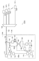
図1は、第1実施形態に係る光線路監視装置14Aを備える光線路監視システム1Aの構成を示す図である。この図に示される光線路監視システム1Aは、局舎10Aに設けられた局側端末11とN個の加入者端末211~21Nとが光分岐器20を介して互いに光ファイバ線路により光学的に接続されていて、局側端末11と各加入者端末21nとの間で光通信を行うものである。ここで、Nは2以上の整数であり、nは1以上N以下の各整数である。このような光通信システムの形態は、PON(Passive Optical Network)と呼ばれる。分岐数Nは4~32が典型的である。
FIG. 1 is a diagram illustrating a configuration of an optical line monitoring system 1A including an optical line monitoring apparatus 14A according to the first embodiment. In the optical line monitoring system 1A shown in this figure, a station-side terminal 11 and N subscriber terminals 21 1 to 21 N provided in a station 10A are optically connected to each other via an optical branching unit 20 via an optical fiber line. Are connected, and optical communication is performed between the station-side terminal 11 and each subscriber terminal 21 n . Here, N is an integer of 2 or more, and n is an integer of 1 or more and N or less. Such an optical communication system is called a PON (Passive Optical Network). The number of branches N is typically 4 to 32.
局舎10Aには、局側端末11の他に光結合器12および光線路監視装置14Aが設けられている。局側端末11と光結合器12とは光ファイバ線路31により光学的に接続されている。また、光結合器12には光線路監視装置14Aも光学的に接続されている。光結合器12と光分岐器20とは第1の光線路32により光学的に接続されている。光分岐器20と各加入者端末21nとは第2の光線路33nにより光学的に接続されている。第1の光線路32および第2の光線路33nは光ファイバで構成される線路であり、好ましくはITU-T G.652準拠のシングルモード光ファイバで構成される。
In addition to the station-side terminal 11, the station building 10A is provided with an optical coupler 12 and an optical line monitoring device 14A. The station-side terminal 11 and the optical coupler 12 are optically connected by an optical fiber line 31. The optical coupler 12 is also optically connected with an optical line monitoring device 14A. The optical coupler 12 and the optical branching device 20 are optically connected by a first optical line 32. The optical branching device 20 and each subscriber terminal 21 n are optically connected by a second optical line 33 n . The first optical line 32 and the second optical line 33 n are lines formed of optical fibers, and are preferably formed of a single mode optical fiber compliant with ITU-T G.652.
各加入者端末21nの光線路に対する接続端には、通信光を透過させ監視光を反射させる光フィルタ22nが接続されているのが好ましい。一般的には通信光として1.26μm~1.62μmの波長の光が用いられるので、監視光としては波長1.65μm帯(1.64~1.66μm)の光が用いられることが好ましく、したがって、各光フィルタ22nは波長1.65μm帯の光を選択的に反射するフィルタであることが好ましい。このような光フィルタはファイバグレーティングなどにより実現され得る。
An optical filter 22 n that transmits communication light and reflects monitoring light is preferably connected to a connection end of each subscriber terminal 21 n with respect to the optical line. In general, light having a wavelength of 1.26 μm to 1.62 μm is used as communication light. Therefore, light having a wavelength of 1.65 μm band (1.64 to 1.66 μm) is preferably used as monitoring light. Therefore, each optical filter 22 n is preferably a filter that selectively reflects light having a wavelength of 1.65 μm. Such an optical filter can be realized by a fiber grating or the like.
光線路監視装置14Aは、OCDR測定を行うOCDR測定部15、OTDR測定を行うOTDR測定部16、OCDR測定部15およびOTDR測定部16のうちの一方を選択して光結合器12に接続する光スイッチ13、制御部17、ならびに記憶装置18を備える。光線路監視装置14Aは、測定対象のPONシステム(第1の光線路32,光分岐器20,第2の光線路33n,光フィルタ22n,加入者端末21n)を監視する。
The optical line monitoring device 14 </ b> A selects one of the OCDR measurement unit 15 that performs OCDR measurement, the OTDR measurement unit 16 that performs OTDR measurement, the OCDR measurement unit 15, and the OTDR measurement unit 16 to connect to the optical coupler 12. A switch 13, a control unit 17, and a storage device 18 are provided. The optical line monitoring device 14A monitors the PON system to be measured (the first optical line 32, the optical branching unit 20, the second optical line 33 n , the optical filter 22 n , and the subscriber terminal 21 n ).
なお、1つのPONシステムにはOCDR測定部15およびOTDR測定部16のうちの一方が接続されるが、他方は別のPONシステムに接続されてもよく、それによって測定部の稼働率を高めて複数のPONシステムを監視対象に含めることができるので、加入者当りの監視コストを低減することができる。
One PON system is connected to one of the OCDR measurement unit 15 and the OTDR measurement unit 16, but the other may be connected to another PON system, thereby increasing the operating rate of the measurement unit. Since a plurality of PON systems can be included in the monitoring target, the monitoring cost per subscriber can be reduced.
OCDR測定部15は、光源41、強度変調器42、光分岐器43、監視光ゲート部44、光サーキュレータ45、偏波変調器46、遅延光ファイバ47、光結合器51、バランス検波器52、第1フィルタ53、電気信号ゲート部54、第2フィルタ55、RF検波器56、AD変換器57、制御部61および信号発生器62~65を備える。
The OCDR measurement unit 15 includes a light source 41, an intensity modulator 42, an optical splitter 43, a monitoring light gate unit 44, an optical circulator 45, a polarization modulator 46, a delay optical fiber 47, an optical coupler 51, a balance detector 52, A first filter 53, an electric signal gate unit 54, a second filter 55, an RF detector 56, an AD converter 57, a control unit 61, and signal generators 62 to 65 are provided.
光源41は、出力光の光周波数を変調することができるものであって、例えば半導体DFBレーザ光源や外部共振器付き半導体レーザ光源等である。光源41は、信号発生器62から出力される周期的な直接変調信号Aを入力して、この直接変調信号Aに基づいて光周波数が周期的に変調された光を出力する。この光源41からの出力光は櫛歯状の光波コヒーレンス関数を有する。
The light source 41 can modulate the optical frequency of the output light, and is, for example, a semiconductor DFB laser light source or a semiconductor laser light source with an external resonator. The light source 41 receives the periodic direct modulation signal A output from the signal generator 62 and outputs light whose optical frequency is periodically modulated based on the direct modulation signal A. The output light from the light source 41 has a comb-like light wave coherence function.
強度変調器42は、信号発生器63から出力される周期的な外部変調信号Bを入力して、この外部変調信号Bに基づいて光源41からの出力光を強度変調して出力する。外部変調信号Bは直接変調信号Aに同期した周期的な信号である。この強度変調器42からの出力光は、強度変調によって光スペクトルが整形されたものとなり、光波コヒーレンス関数に含まれるノイズが低減されたものとなる。
The intensity modulator 42 receives the periodic external modulation signal B output from the signal generator 63, modulates the output light from the light source 41 based on the external modulation signal B, and outputs the modulated output light. The external modulation signal B is a periodic signal synchronized with the direct modulation signal A. The output light from the intensity modulator 42 has an optical spectrum shaped by intensity modulation, and noise included in the light wave coherence function is reduced.
光分岐器43は、光源41から出力され必要に応じて強度変調器42により強度変調された光を入力し、この入力光を監視光と参照光とに2分岐して、そのうち監視光を監視光ゲート部44へ出力し、参照光を偏波変調器46へ出力する。
The optical splitter 43 receives light output from the light source 41 and intensity-modulated by the intensity modulator 42 as necessary, branches the input light into monitoring light and reference light, and monitors the monitoring light. The light is output to the optical gate 44 and the reference light is output to the polarization modulator 46.
監視光ゲート部44は、光分岐器43から出力された監視光を入力し、また、信号発生器64から出力された監視光ゲート信号Cをも入力する。監視光ゲート信号Cは、一定周期Tでゲート幅w1のパルスを有する周期的な信号である。監視光ゲート信号Cのゲート幅w1は、直接変調信号Aおよび外部変調信号Bそれぞれの変調周期にほぼ等しい。監視光ゲート部44は、このような監視光ゲート信号Cのゲート幅w1のパルスの期間のみ、光分岐器43から出力された監視光を光サーキュレータ45へ出力する。
The monitoring light gate unit 44 receives the monitoring light output from the optical splitter 43 and also receives the monitoring light gate signal C output from the signal generator 64. The monitoring light gate signal C is a periodic signal having a pulse with a gate width w1 at a constant period T. The gate width w1 of the monitoring light gate signal C is substantially equal to the modulation period of each of the direct modulation signal A and the external modulation signal B. The monitoring light gate unit 44 outputs the monitoring light output from the optical branching device 43 to the optical circulator 45 only during the pulse period of the gate width w1 of the monitoring light gate signal C.
光サーキュレータ45は、監視光ゲート部44からパルス化されて出力された監視光を入力し、その監視光を光結合器12へ出力する。また、光サーキュレータ45は、光結合器12から到達した光を入力し、その光を光結合器51へ出力する。
The optical circulator 45 receives the monitoring light that has been pulsed and output from the monitoring light gate 44 and outputs the monitoring light to the optical coupler 12. The optical circulator 45 receives the light that has arrived from the optical coupler 12 and outputs the light to the optical coupler 51.
光サーキュレータ45から出力された監視光は、光スイッチ13および光結合器12を経て第1の光線路32へ送出され、さらに、第1の光線路32,光分岐器20,第2の光線路33nを経て光フィルタ22nに達する。この監視光の伝搬の際に生じる反射光(フレネル反射光やレイリー散乱光)は、監視光の伝搬経路と逆方向の経路を辿って、光結合器12、光スイッチ13および光サーキュレータ45を経て光結合器51に入力される。このとき、各第2の光線路33nの末端と加入者端末21nとの間に光フィルタ22nが配置されていることにより、OTDR測定およびOCDR測定の際に光フィルタ22nにより監視光が反射されて生じた反射光を検出することで光線路の断線などの異常を検出することができる。
The monitoring light output from the optical circulator 45 is sent to the first optical line 32 through the optical switch 13 and the optical coupler 12, and further, the first optical line 32, the optical branching unit 20, and the second optical line. reaching the optical filter 22 n through 33 n. Reflected light (Fresnel reflected light or Rayleigh scattered light) generated during the propagation of the monitoring light follows a path opposite to the propagation path of the monitoring light, and passes through the optical coupler 12, the optical switch 13, and the optical circulator 45. Input to the optical coupler 51. At this time, since the optical filter 22 n is disposed between the end of each second optical line 33 n and the subscriber terminal 21 n , the monitoring light is transmitted by the optical filter 22 n during the OTDR measurement and the OCDR measurement. By detecting the reflected light generated by reflecting the light, it is possible to detect abnormalities such as disconnection of the optical line.
特に、光フィルタの反射率R[dB]は、光分岐器の分岐数をNとして、下記(1)式を満たすことが好ましい。ここで、R0は、光サーキュレータ45、光結合器12、第1の光線路32および光分岐器20における内部反射率であり、典型的には-40dBである。この(1)式を満たすことにより、光フィルタ22nで反射されて監視装置に到達する反射光のパワーは、光分岐器20の上流(監視装置側)での意図しない反射により生じた反射光のパワーに比べて大きくなるので、光分岐器20上流での意図しない反射による雑音の影響が相対的に低減され、測定時間が短縮される。
In particular, the reflectance R [dB] of the optical filter preferably satisfies the following expression (1), where N is the number of branches of the optical branching unit. Here, R0 is the internal reflectance in the optical circulator 45, the optical coupler 12, the first optical line 32, and the optical branching device 20, and is typically −40 dB. By satisfying this equation (1), the power of the reflected light that is reflected by the optical filter 22 n and reaches the monitoring device is reflected light caused by unintentional reflection upstream of the optical branching device 20 (monitoring device side). Therefore, the influence of noise due to unintentional reflection upstream of the optical branching device 20 is relatively reduced, and the measurement time is shortened.
R > R0+ 20log10(N) …(1)
R> R0 + 20log 10 (N) (1)
光分岐器43と光結合器51との間の参照光の光路に遅延光ファイバ47が設けられているのが好ましい。遅延光ファイバ47は、光サーキュレータ45から光結合器51に入力される反射光(監視光の戻り光)と、光分岐器43から光結合器51に入力される参照光と、の間の遅延時間を設定する。測定する距離範囲内の任意の位置で監視光が反射されて生じた反射光と参照光との間の遅延時間が、光源41の出力光のコヒーレンス時間より長くなるように、遅延光ファイバ47の長さを設定するのが好ましい。遅延時間がコヒーレンス時間より短い範囲では空間分解能は遅延時間と共に増大し、遅延時間がコヒーレンス時間より長い範囲では空間分解能は略一定値となるので、遅延時間を上記のように設定することにより、測定範囲内での空間分解能のバラツキを低減することができる。
It is preferable that a delay optical fiber 47 is provided in the optical path of the reference light between the optical splitter 43 and the optical coupler 51. The delay optical fiber 47 is a delay between the reflected light (monitoring light return light) input from the optical circulator 45 to the optical coupler 51 and the reference light input from the optical splitter 43 to the optical coupler 51. Set the time. The delay optical fiber 47 is designed so that the delay time between the reflected light generated by reflecting the monitoring light at an arbitrary position within the distance range to be measured and the reference light is longer than the coherence time of the output light of the light source 41. It is preferable to set the length. When the delay time is shorter than the coherence time, the spatial resolution increases with the delay time, and when the delay time is longer than the coherence time, the spatial resolution becomes a substantially constant value. Variations in spatial resolution within the range can be reduced.
光分岐器43と光結合器51との間の参照光の光路に偏波変調器46が設けられているのも好ましい。偏波変調器46は、光分岐器43から出力された参照光を入力し、その参照光の偏波状態を変えて出力する。反射光(監視光の戻り光)と参照光とを互いに干渉させて検出する際、その検出効率は2つの光の偏波状態の相対関係に依存するので、反射光および参照光の少なくとも一方の偏波状態を変えながら測定を行い、複数の偏波状態で測定した結果に対して平均化などの演算処理を施して、偏波状態に依存しない測定結果を得ることが好ましい。
It is also preferable that a polarization modulator 46 is provided in the optical path of the reference light between the optical splitter 43 and the optical coupler 51. The polarization modulator 46 receives the reference light output from the optical splitter 43, changes the polarization state of the reference light, and outputs it. When the reflected light (return light of the monitoring light) and the reference light are detected by interfering with each other, the detection efficiency depends on the relative relationship between the polarization states of the two lights, so that at least one of the reflected light and the reference light It is preferable to perform measurement while changing the polarization state, and perform arithmetic processing such as averaging on the measurement results in a plurality of polarization states to obtain measurement results that do not depend on the polarization state.
光結合器51は、光サーキュレータ45から出力された反射光(監視光の戻り光)を入力するとともに、光分岐器43から出力されて偏波変調器46および遅延光ファイバ47を経た参照光を入力し、これら入力した反射光と参照光とを合波してバランス検波器52へ出力する。光結合器51として例えば3dBカプラが用いられる。
The optical coupler 51 receives the reflected light (return light of the monitoring light) output from the optical circulator 45 and also outputs the reference light output from the optical splitter 43 and passed through the polarization modulator 46 and the delay optical fiber 47. The input reflected light and reference light are combined and output to the balance detector 52. For example, a 3 dB coupler is used as the optical coupler 51.
バランス検波器52は、光結合器51により合波された反射光および参照光を入力して、これら反射光と参照光とが互いに干渉してなる干渉光の強度を示す電気信号を第1フィルタ53へ出力する。すなわち、バランス検波器52は、干渉光の強度に応じた値の電気信号を出力する光電変換部として作用する。
The balance detector 52 receives the reflected light and the reference light combined by the optical coupler 51, and outputs an electric signal indicating the intensity of the interference light formed by the interference between the reflected light and the reference light to the first filter. To 53. That is, the balance detector 52 functions as a photoelectric conversion unit that outputs an electric signal having a value corresponding to the intensity of the interference light.
第1フィルタ53は、バランス検波器52から出力される電気信号を入力し、この電気信号に含まれる不要雑音を除去して、その除去後の電気信号を電気信号ゲート部54へ出力する。第1フィルタ53は、入力した電気信号の直流成分を除去するフィルタであることが好ましい。直流成分の雑音は、光結合器51およびバランス検波器52におけるバランスの誤差によって生じるが、これを第1フィルタ53により除去することにより、後段の電気信号ゲート部54における雑音発生量を低減することができる。
The first filter 53 receives the electrical signal output from the balance detector 52, removes unnecessary noise contained in the electrical signal, and outputs the electrical signal after the removal to the electrical signal gate unit 54. The first filter 53 is preferably a filter that removes the DC component of the input electrical signal. The DC component noise is caused by a balance error in the optical coupler 51 and the balance detector 52. By removing this error by the first filter 53, the amount of noise generation in the subsequent electrical signal gate 54 is reduced. Can do.
電気信号ゲート部54は、バランス検波器52から出力されて第1フィルタ53を経た電気信号を入力し、また、信号発生器65から出力された電気信号ゲート信号Dをも入力する。電気信号ゲート信号Dは、一定周期Tでゲート幅w2のパルスを有する周期的な信号である。電気信号ゲート信号Dの周期Tは監視光ゲート信号Cの周期Tとほぼ等しい。電気信号ゲート信号Dのパルス中心は、監視光ゲート信号Cのパルス中心に対してゲート遅延時間dだけ遅れている。
The electrical signal gate 54 receives the electrical signal output from the balance detector 52 and passed through the first filter 53, and also receives the electrical signal gate signal D output from the signal generator 65. The electrical signal gate signal D is a periodic signal having a pulse with a gate width w2 at a constant period T. The period T of the electric signal gate signal D is substantially equal to the period T of the monitoring light gate signal C. The pulse center of the electrical signal gate signal D is delayed from the pulse center of the monitoring light gate signal C by a gate delay time d.
電気信号ゲート部54は、このような電気信号ゲート信号Dのゲート幅w2のパルスの期間のみ、第1フィルタ53から出力された電気信号を第2フィルタ55へ出力する。電気信号ゲート部54から第2フィルタ55へ出力される電気信号はパルス信号となる。電気信号ゲート部54としては、電気信号ゲート信号Dのレベルに応じてON/OFF動作するオペアンプ回路が用いられる。
The electric signal gate unit 54 outputs the electric signal output from the first filter 53 to the second filter 55 only during the pulse period of the gate width w2 of the electric signal gate signal D. The electric signal output from the electric signal gate unit 54 to the second filter 55 is a pulse signal. As the electrical signal gate unit 54, an operational amplifier circuit that performs ON / OFF operation according to the level of the electrical signal gate signal D is used.
第2フィルタ55は、電気信号ゲート部54から出力されたパルス状の電気信号を入力し、その入力した電気信号の特定周波数帯域のものを選択的にRF検波器56へ出力する。第2フィルタ55における上記特定周波数帯域は、電気信号ゲート信号Dの繰り返し周波数f(=1/T)の整数倍の周波数nf(ただしnは自然数)を含まないことが好ましい。特に、上記特定周波数帯域はf(=1/T)の半奇数倍の周波数を含みf/2以下の帯域幅を持つことが好ましい。電気信号ゲート部に入力される信号は、直流および1/pの整数倍の周波数に雑音を持っており、この雑音が電気信号ゲート部を通過することにより、fの整数倍の周波数に雑音が拡散する。しかし、上記のように周波数帯域を設定することにより、電気信号ゲート部54において生じる雑音の影響を低減することができ、測定のSN比を改善することができて、測定時間を短縮することができる。
The second filter 55 receives the pulsed electric signal output from the electric signal gate 54 and selectively outputs the input electric signal having a specific frequency band to the RF detector 56. The specific frequency band in the second filter 55 preferably does not include a frequency nf (where n is a natural number) that is an integral multiple of the repetition frequency f (= 1 / T) of the electrical signal gate signal D. In particular, the specific frequency band preferably includes a frequency that is half an odd number multiple of f (= 1 / T) and has a bandwidth of f / 2 or less. The signal input to the electric signal gate unit has noise at a frequency that is an integral multiple of DC and 1 / p. When this noise passes through the electric signal gate unit, noise is generated at a frequency that is an integral multiple of f. Spread. However, by setting the frequency band as described above, the influence of noise generated in the electrical signal gate unit 54 can be reduced, the SN ratio of measurement can be improved, and the measurement time can be shortened. it can.
RF検波器56は、第2フィルタ55から出力される電気信号を入力し、干渉成分の大きさに相当する電気信号に変換してAD変換器57へ出力する。AD変換器57は、RF検波器56から出力される電気信号を入力し、この電気信号(アナログ信号)をデジタル信号に変換して、このデジタル信号を制御部61へ出力する。このデジタル信号の値は、光源41における光周波数変調の周期pおよびゲート遅延時間dにより決定される光線路上の位置zにおいて生じた反射光のパワーを表す。
The RF detector 56 receives the electrical signal output from the second filter 55, converts the electrical signal into an electrical signal corresponding to the magnitude of the interference component, and outputs the electrical signal to the AD converter 57. The AD converter 57 receives the electrical signal output from the RF detector 56, converts the electrical signal (analog signal) into a digital signal, and outputs the digital signal to the control unit 61. The value of the digital signal represents the power of the reflected light generated at the position z on the optical line determined by the optical frequency modulation period p and the gate delay time d in the light source 41.
制御部61は、AD変換器57から出力されたデジタル値を入力して、このデジタル値と位置zとを互いに関連付けて記憶する。制御部61は、信号発生器62~65それぞれを制御して、信号発生器62から出力される直接変調信号Aの変調周期p、信号発生器63から出力される外部変調信号Bの変調周期p、信号発生器64から出力される監視光ゲート信号Cの周期Tおよびゲート幅w1、信号発生器65から出力される電気信号ゲート信号Dの周期Tおよびゲート幅w2、ならびに、ゲート遅延時間dを指定する。これにより、制御部61は、測定対象である光線路上の測定位置zを指定して、その位置zにおいて生じた反射光のパワーを表すデジタル値をAD変換器57から取得する。そして、制御部61は、光線路における監視光伝搬方向に沿った反射率分布を求める。
The control unit 61 receives the digital value output from the AD converter 57 and stores the digital value and the position z in association with each other. The control unit 61 controls each of the signal generators 62 to 65 to control the modulation period p of the direct modulation signal A output from the signal generator 62 and the modulation period p of the external modulation signal B output from the signal generator 63. The period T and gate width w1 of the monitoring light gate signal C output from the signal generator 64, the period T and gate width w2 of the electrical signal gate signal D output from the signal generator 65, and the gate delay time d specify. As a result, the control unit 61 designates the measurement position z on the optical line to be measured, and acquires a digital value representing the power of the reflected light generated at the position z from the AD converter 57. And the control part 61 calculates | requires the reflectance distribution along the monitoring light propagation direction in an optical line.
OTDR測定部16は、光源71、光サーキュレータ72、光検出器73、AD変換器74、制御部75、および信号発生器76を備える。
The OTDR measurement unit 16 includes a light source 71, an optical circulator 72, a photodetector 73, an AD converter 74, a control unit 75, and a signal generator 76.
光源71は、信号発生器76から出力されるパルス信号を入力して、このパルス信号により駆動されてパルス状の監視光を発生する光源であり、例えば半導体レーザを用いることができる。光サーキュレータ72は、光源71から出力された監視光を入力し、その監視光を光結合器12へ出力する。また、光サーキュレータ72は、光結合器12から到達した光を入力し、その光を光検出器73へ出力する。
The light source 71 is a light source that receives the pulse signal output from the signal generator 76 and is driven by the pulse signal to generate pulsed monitoring light. For example, a semiconductor laser can be used. The optical circulator 72 receives the monitoring light output from the light source 71 and outputs the monitoring light to the optical coupler 12. Further, the optical circulator 72 receives light that has arrived from the optical coupler 12 and outputs the light to the photodetector 73.
光検出器73は、光サーキュレータ72から光を入力して検出し、その光強度に応じた電気信号を出力する。電気信号は時間とともに変化し、その変化は光線路に沿った反射率の分布を反映する。AD変換器74は、検出器73から電気信号を入力し、この電気信号(アナログ信号)を逐次デジタル信号に変換し、デジタル信号系列として制御部75へ出力する。制御部75は、AD変換器74から出力されたデジタル信号系列を入力して、OTDR測定結果として記録する。
The photodetector 73 receives light from the optical circulator 72 and detects it, and outputs an electrical signal corresponding to the light intensity. The electrical signal changes with time, and the change reflects the reflectance distribution along the optical line. The AD converter 74 receives an electric signal from the detector 73, sequentially converts the electric signal (analog signal) into a digital signal, and outputs the digital signal series to the control unit 75. The control unit 75 inputs the digital signal sequence output from the AD converter 74 and records it as an OTDR measurement result.
制御部17は、OCDR測定部15の制御部61およびOTDR測定部16の制御部75と接続され、これらの制御部61,75に対して測定範囲などの測定条件を出力するとともに、制御部61,75から測定結果のデータを入力する。また、制御部17は記憶装置18に接続されている。記憶装置18には、監視装置から各光フィルタ22nまでの距離や、光フィルタ22nおよび加入者端末21nの設置位置(建物の名称や建物内での位置など)などの情報が格納される。
The control unit 17 is connected to the control unit 61 of the OCDR measurement unit 15 and the control unit 75 of the OTDR measurement unit 16, and outputs measurement conditions such as a measurement range to these control units 61 and 75, and the control unit 61. , 75 to input measurement result data. The control unit 17 is connected to the storage device 18. The storage device 18 stores information such as the distance from the monitoring device to each optical filter 22 n and the installation positions of the optical filter 22 n and the subscriber terminal 21 n (such as the name of the building and the position in the building). The
制御部17は、反射率分布の中から光フィルタ22nに由来する反射率のピークを検出し、事前に準備された光フィルタ22nまでの距離の情報と反射率ピークの距離とを照合して、各光フィルタ22nからの反射光が検出されたか否かを判定する。そして、制御部17は、反射光が検出される加入者端末と反射光が検出されない加入者端末とが混在する場合は、後者の加入者端末が所属する加入者側光ファイバに断線などの異常があると判定し、異常を表示する。
The control unit 17 detects the reflectance peak derived from the optical filter 22 n from the reflectance distribution, and collates the information on the distance to the optical filter 22 n prepared in advance with the distance of the reflectance peak. Then, it is determined whether or not the reflected light from each optical filter 22 n is detected. When the subscriber terminal in which the reflected light is detected and the subscriber terminal in which the reflected light is not mixed, the control unit 17 detects an abnormality such as a disconnection in the subscriber-side optical fiber to which the latter subscriber terminal belongs. It is determined that there is an error and an error is displayed.
また、制御部17は、光フィルタ22nまでの距離情報に基づいて、光フィルタ22nの近傍に限定してOCDR測定を行い、光フィルタ22nからの反射光の有無や反射率の大きさを知ることにより、その光フィルタ22nが属する第2の光線路33nの異常の有無を判定するための時間を短縮することができる。
The control unit 17, based on the distance information to the optical filter 22 n, performs OCDR measurement is limited to the vicinity of the optical filter 22 n, the presence and the reflectance of the reflected light from the optical filter 22 n size By knowing, it is possible to shorten the time for determining whether or not the second optical line 33 n to which the optical filter 22 n belongs is abnormal.
さらに、制御部17は、OCDR測定部15に対してOCDR測定を行わせて取得させたOCDR測定結果と、OTDR測定部16に対してOTDR測定を行わせて取得させたOTDR測定結果とに基づいて、後述するような所定の演算を行う。
Further, the control unit 17 is based on the OCDR measurement result obtained by performing the OCDR measurement with the OCDR measurement unit 15 and the OTDR measurement result obtained by performing the OTDR measurement with the OTDR measurement unit 16. Then, a predetermined calculation as described later is performed.
次に、図2~図4を用いて、直接変調信号A、外部変調信号B、監視光ゲート信号C、電気信号ゲート信号D、および、RF検波器56から出力される電気信号、等について説明する。
Next, the direct modulation signal A, the external modulation signal B, the monitoring light gate signal C, the electric signal gate signal D, the electric signal output from the RF detector 56, etc. will be described with reference to FIGS. To do.
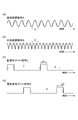
図2は、直接変調信号A、外部変調信号B、監視光ゲート信号Cおよび電気信号ゲート信号Dそれぞれの波形を示す図である。同図(a)は、信号発生器62から光源41に与えられる直接変調信号Aの波形を示す。同図(b)は、信号発生器63から強度変調器42に与えられる外部変調信号Bの波形を示す。同図(c)は、信号発生器64から監視光ゲート部44に与えられる監視光ゲート信号Cの波形を示す。また、同図(d)は、信号発生器65から電気信号ゲート部54に与えられる電気信号ゲート信号Dの波形を示す。
FIG. 2 is a diagram showing waveforms of the direct modulation signal A, the external modulation signal B, the monitoring light gate signal C, and the electric signal gate signal D. FIG. 6A shows the waveform of the direct modulation signal A given from the signal generator 62 to the light source 41. FIG. 4B shows the waveform of the external modulation signal B given from the signal generator 63 to the intensity modulator 42. FIG. 4C shows the waveform of the monitoring light gate signal C supplied from the signal generator 64 to the monitoring light gate unit 44. FIG. 4D shows the waveform of the electric signal gate signal D supplied from the signal generator 65 to the electric signal gate unit 54.
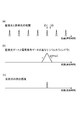
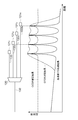
図3は、反射光(戻り監視光)と参照光との相関強度、監視光ゲート信号Cと電気信号ゲート信号Dとの重なり(パルスウィンドウ)、および、反射光の検出感度それぞれを、光線路上の位置zとの関係において示す図である。同図(a)は、反射光(戻り監視光)と参照光との相関強度分布を示す。同図(b)は、監視光ゲート信号Cと電気信号ゲート信号Dとの重なり(パルスウィンドウ)を示す。また、同図(c)は、反射光の検出感度分布を示す。
FIG. 3 shows the correlation intensity between the reflected light (return monitoring light) and the reference light, the overlap (pulse window) of the monitoring light gate signal C and the electric signal gate signal D, and the detection sensitivity of the reflected light on the optical line. It is a figure shown in relation to position z. FIG. 4A shows the correlation intensity distribution between the reflected light (return monitoring light) and the reference light. FIG. 4B shows the overlap (pulse window) of the monitoring light gate signal C and the electrical signal gate signal D. FIG. 3C shows the detection sensitivity distribution of reflected light.
図4は、図3(a)中に示された光線路における位置z1,z2それぞれからの反射光による干渉信号のスペクトルを示す図である。同図(a)は、図3(a)中に示された相関が高い位置z1からの反射光による干渉信号のスペクトルを示す。また、同図(b)は、図3(a)中に示された相関が低い位置z2からの反射光による干渉信号のスペクトルを示す。
FIG. 4 is a diagram showing a spectrum of an interference signal by reflected light from each of the positions z1 and z2 in the optical line shown in FIG. FIG. 6A shows the spectrum of an interference signal due to reflected light from the position z1 having a high correlation shown in FIG. FIG. 3B shows a spectrum of an interference signal caused by reflected light from the position z2 having a low correlation shown in FIG.
図2(a)に示されるように、直接変調信号Aは、周期pを有する周期的な信号であって、光源41からの出力光を光周波数変調するための信号である。周期pは、光線路における測定位置zを規定する。測定対象である光線路の位置zで反射・散乱されて生じた反射光(戻り監視光)の参照光に対する遅延時間差dが下記(2)式の条件を満たすときに、その位置(図3(a)中の位置z1)からの反射光と参照光との変調の位相が同期して反射光と参照光との相関が高まる。一方、下記(2)式の条件を満たさない位置(図3(a)中の位置z2)で反射・散乱されて生じた反射光(戻り監視光)は参照光との相関が低い。
As shown in FIG. 2 (a), the direct modulation signal A is a periodic signal having a period p, and is a signal for optical frequency modulating the output light from the light source 41. The period p defines the measurement position z in the optical line. When the delay time difference d with respect to the reference light of the reflected light (return monitoring light) reflected and scattered at the position z of the optical line to be measured satisfies the condition of the following equation (2) (see FIG. 3 ( The phase of modulation of the reflected light from the position z1) and the reference light in a) is synchronized, and the correlation between the reflected light and the reference light increases. On the other hand, the reflected light (return monitoring light) that is reflected and scattered at a position that does not satisfy the condition of the following expression (2) (position z2 in FIG. 3A) has a low correlation with the reference light.
d/p=整数 …(2)
D / p = integer (2)
反射光(戻り監視光)と参照光との相関が高い場合(図3(a)中の位置z1の場合)には、両光による干渉信号のスペクトルは監視光の線幅と同程度の周波数帯域に局在する(図4(a)参照)。一方、相関が低い場合(図3(a)中の位置z2の場合)には、干渉信号のスペクトルは監視光の光周波数変調の振幅と同程度の周波数帯域にわたって拡散される(図4(b)参照)。したがって、監視光の線幅より大きな振幅で光周波数変調を施すことにより、特定の測定位置からの反射光を選択的に検出することができる。空間分解能は光周波数変調の振幅にほぼ逆比例するので、周波数変調の振幅は大きいほうが好ましい。一方、光源41としてのレーザダイオードに注入することができる電流の上限値は損傷閾値で規定され、下限値はゼロであるので、それによって振幅の上限が規定される。なお、直接変調信号Aの波形は、本実施形態では正弦波であるが、矩形波や三角波などの様々な周期的波形であってもよい。
When the correlation between the reflected light (return monitoring light) and the reference light is high (in the case of the position z1 in FIG. 3 (a)), the spectrum of the interference signal due to both lights has a frequency comparable to the line width of the monitoring light. It is localized in the band (see FIG. 4A). On the other hand, when the correlation is low (in the case of the position z2 in FIG. 3A), the spectrum of the interference signal is spread over a frequency band approximately equal to the amplitude of the optical frequency modulation of the monitoring light (FIG. 4B). )reference). Therefore, reflected light from a specific measurement position can be selectively detected by performing optical frequency modulation with an amplitude larger than the line width of the monitoring light. Since the spatial resolution is approximately inversely proportional to the amplitude of the optical frequency modulation, it is preferable that the amplitude of the frequency modulation is large. On the other hand, since the upper limit value of the current that can be injected into the laser diode as the light source 41 is defined by the damage threshold value and the lower limit value is zero, the upper limit value of the amplitude is defined thereby. The waveform of the direct modulation signal A is a sine wave in this embodiment, but may be various periodic waveforms such as a rectangular wave and a triangular wave.
より好ましくは、空間分解能は9cm以下とすることが好ましい。それにより、異なる第2の光線路に属する光フィルタの反射ピークの重なりを避けるためには、第2の光線路の長さを互いに9cm以上異ならせれば十分であり、各第2の光線路には9cmの余長を確保すれば良い。一方、第2の光線路として用いられる光ファイバとしては一般的にはITU-T G.652準拠のシングルモード光ファイバのうち、曲げ特性を強化して許容曲げ半径を15mmとした光ファイバが普及している。この許容曲げ半径15mmで1周巻くことにより、9cmの余長を収納することができるので、空間分解能を9cm以下とすることにより、余長収納のスペースを最小化することができる。
More preferably, the spatial resolution is preferably 9 cm or less. Thereby, in order to avoid overlapping of reflection peaks of optical filters belonging to different second optical lines, it is sufficient to make the lengths of the second optical lines different from each other by 9 cm or more. It is sufficient to secure an extra length of 9 cm. On the other hand, as an optical fiber used as the second optical line, in general, an optical fiber having an allowable bending radius of 15 mm is strengthened among single-mode optical fibers compliant with ITU-T G.652. is doing. By winding one turn at this allowable bending radius of 15 mm, a surplus length of 9 cm can be accommodated. Therefore, by setting the spatial resolution to 9 cm or less, the surplus length accommodation space can be minimized.
図2(b)に示されるように、外部変調信号Bは、直接変調信号Aに同期した周期的な信号であって、光源41からの出力光を強度変調器42により直接変調信号Aに同期して強度変調するための信号である。これによって、強度変調器42から出力される光のスペクトルを整形することができる。OCDRにおける反射光検出感度は距離の関数として表され、この距離の関数は光波コヒーレンス関数として知られる。特定の測定位置からの反射光を選択的に検出するためには、光波コヒーレンス関数はデルタ関数列に近いことが好ましい。一方、光波コヒーレンス関数は光のパワースペクトルのフーリエ変換で与えられるので、強度変調によってスペクトルを整形することにより、OCDRによる反射光測定の位置選択性を高めることができる。
As shown in FIG. 2B, the external modulation signal B is a periodic signal synchronized with the direct modulation signal A, and the output light from the light source 41 is synchronized with the direct modulation signal A by the intensity modulator 42. And a signal for intensity modulation. Thereby, the spectrum of the light output from the intensity modulator 42 can be shaped. The reflected light detection sensitivity in OCDR is expressed as a function of distance, and this function of distance is known as a light wave coherence function. In order to selectively detect reflected light from a specific measurement position, the light wave coherence function is preferably close to a delta function sequence. On the other hand, since the light wave coherence function is given by Fourier transform of the power spectrum of light, the position selectivity of the reflected light measurement by OCDR can be enhanced by shaping the spectrum by intensity modulation.
図2(c)に示されるように、監視光ゲート信号Cは、一定周期Tでゲート幅w1のパルスを有する周期的な信号であって、監視光ゲート部44から出力される監視光をゲート幅w1のパルスの期間のみに選択するための信号である。また、図2(d)に示されるように、電気信号ゲート信号Dは、一定周期Tでゲート幅w2のパルスを有する周期的な信号であって、電気信号ゲート部54から出力される電気信号をゲート幅w2のパルスの期間のみに選択するための信号である。
As shown in FIG. 2 (c), the monitoring light gate signal C is a periodic signal having a pulse with a gate width w1 at a constant period T, and the monitoring light output from the monitoring light gate unit 44 is gated. This is a signal for selection only during the period of the pulse of width w1. Further, as shown in FIG. 2D, the electric signal gate signal D is a periodic signal having a pulse with a gate width w2 at a constant period T, and is an electric signal output from the electric signal gate unit 54. Is a signal for selecting only during the pulse period of the gate width w2.
電気信号ゲート信号Dの周期Tは監視光ゲート信号Cの周期Tと等しい。電気信号ゲート信号Dのパルス中心は、監視光ゲート信号Cのパルス中心に対してゲート遅延時間dだけ遅れている。このようにすることにより、光線路における特定の測定距離範囲(パルスウィンドウ)からの反射光が選択的に検出される(図3(b),(c)参照)。
The period T of the electric signal gate signal D is equal to the period T of the monitoring light gate signal C. The pulse center of the electrical signal gate signal D is delayed from the pulse center of the monitoring light gate signal C by a gate delay time d. By doing in this way, the reflected light from the specific measurement distance range (pulse window) in an optical line is selectively detected (refer FIG.3 (b), (c)).
直接変調信号Aの周期p、監視光ゲート信号Cのゲート幅w1および電気信号ゲート信号Dのゲート幅w2が、下記(3)式の関係を満たすことが好ましい。このようにすることにより、パルスウィンドウの中心において反射光(戻り監視光)と参照光との相関がピークとなるようにゲート遅延時間dを定めれば、パルスウィンドウの中に存在し得る相関ピークは1つに制限される。
It is preferable that the period p of the direct modulation signal A, the gate width w1 of the monitoring light gate signal C, and the gate width w2 of the electric signal gate signal D satisfy the relationship of the following expression (3). In this way, if the gate delay time d is determined so that the correlation between the reflected light (return monitoring light) and the reference light has a peak at the center of the pulse window, a correlation peak that can exist in the pulse window. Is limited to one.
w1+w2<2p …(3)
W1 + w2 <2p ... (3)
監視光ゲート信号Cおよび電気信号ゲート信号Dそれぞれの周期Tは、直接変調信号Aの周期pの整数倍であることが好ましい。第2フィルタ55の透過帯域は、監視光ゲート信号Cおよび電気信号ゲート信号Dそれぞれの繰り返し周波数f(=1/T)の整数倍の周波数を含まないことが好ましい。
The period T of each of the monitoring light gate signal C and the electric signal gate signal D is preferably an integral multiple of the period p of the direct modulation signal A. It is preferable that the transmission band of the second filter 55 does not include a frequency that is an integral multiple of the repetition frequency f (= 1 / T) of each of the monitoring light gate signal C and the electrical signal gate signal D.
これは以下の理由による。バランス検波器52に入力される反射光(戻り監視光)の電界の複素振幅をE1とし、バランス検波器52に入力される参照光の電界の複素振幅をE2とすると、バランス検波器52から出力される電気信号(電流I1)は、比例係数を省略すると、下記(4)式で表される。この式の第1項は非干渉性の雑音である。εはバランス検出による同相成分の減衰係数を示す。εは、ゼロであることが理想的であるが、実際には10-5またはそれ以上の値をとることが多く、雑音の原因となる。第2項は干渉信号である。
This is due to the following reason. If the complex amplitude of the electric field of the reflected light (return monitoring light) input to the balance detector 52 is E1, and the complex amplitude of the electric field of the reference light input to the balance detector 52 is E2, the output from the balance detector 52 The electric signal (current I1) to be performed is expressed by the following equation (4) when the proportionality coefficient is omitted. The first term of this equation is incoherent noise. ε represents the attenuation coefficient of the in-phase component by balance detection. ε is ideally zero, but actually takes a value of 10 −5 or more, which causes noise. The second term is an interference signal.
I1 = ε(|E1|2+|E2|2) + 2Re[E1・E2*] …(4)
I1 = ε (| E1 | 2 + | E2 | 2 ) + 2Re [E1 · E2 * ] (4)
非干渉雑音は、光強度に比例し、スペクトル成分としては、平均パワーに相当する直流成分と、光源41での寄生強度変調および外部強度変調による変調成分(周期p)とを有する。非干渉雑音は、第1フィルタ53によって直流成分が減衰された後、電気信号ゲート部54において電気信号ゲート信号Dによってパルスが切り出される。
The non-interference noise is proportional to the light intensity, and has a DC component corresponding to the average power and a modulation component (period p) due to parasitic intensity modulation and external intensity modulation at the light source 41 as spectral components. As for the non-interference noise, after the DC component is attenuated by the first filter 53, a pulse is cut out by the electric signal gate signal D in the electric signal gate unit 54.
電気信号ゲート部54から出力される電気信号(電流I2)は下記(5)式で表される。ここで、Fは、電気信号ゲート信号Dであり、周期Tを有する。この式の第1項は非干渉性雑音であり、第2項は干渉信号である。
The electrical signal (current I2) output from the electrical signal gate 54 is expressed by the following equation (5). Here, F is an electric signal gate signal D and has a period T. The first term of this equation is incoherent noise and the second term is an interference signal.
I2 = εF(|E1|2+|E2|2) + 2F・Re[E1・E2*] …(5)
I2 = εF (| E1 | 2 + | E2 | 2 ) + 2F · Re [E1 · E2 * ] (5)
この(5)式の第1項の非干渉性雑音は、周波数(1/p)の関数と周波数(1/T)の関数との積であるから、i,jを整数として、周波数(i/p+j/T)に出現する雑音となる。ここで、監視光ゲート信号Cおよび電気信号ゲート信号Dそれぞれのパルス繰返し周期Tが直接変調信号Aの変調周期pの整数倍に等しくなるようにパルス周期を設定すると、非干渉性の雑音が生じる周波数は、iを整数として、i/Tに限定される。したがって、周波数(i/T)を含まない周波数帯域の成分を第2フィルタ55により切り出して検出帯域とすることにより、雑音の少ない測定結果を得ることができる。
The incoherent noise of the first term of the equation (5) is a product of a function of frequency (1 / p) and a function of frequency (1 / T). / P + j / T). Here, when the pulse period is set so that the pulse repetition period T of each of the monitoring light gate signal C and the electric signal gate signal D is equal to an integral multiple of the modulation period p of the direct modulation signal A, incoherent noise is generated. The frequency is limited to i / T, where i is an integer. Therefore, a measurement result with less noise can be obtained by cutting out the component of the frequency band not including the frequency (i / T) by using the second filter 55 as the detection band.
次に、図5~図8を用いて、第1実施形態に係る光線路監視装置14Aの動作について説明するとともに、OTDR測定および複数のOCDR測定により光線路に沿った反射率分布の高分解能での測定のための時間を短縮する方法について説明する。
Next, the operation of the optical line monitoring apparatus 14A according to the first embodiment will be described with reference to FIGS. 5 to 8, and the reflectance distribution along the optical line with high resolution by OTDR measurement and a plurality of OCDR measurements. A method for shortening the time required for the measurement will be described.
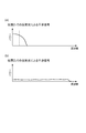
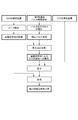
図5は、第1実施形態に係る光線路監視装置14Aの動作を説明するフローチャートである。図6は、第1実施形態に係る光線路監視システム1Aの構成を簡略化して示す図である。図7および図8は、第1実施形態に係る光線路監視システム1Aにおいて反射率分布を測定した場合の測定波形の計算結果を示す図である。
FIG. 5 is a flowchart for explaining the operation of the optical line monitoring apparatus 14A according to the first embodiment. FIG. 6 is a diagram showing a simplified configuration of the optical line monitoring system 1A according to the first embodiment. 7 and 8 are diagrams illustrating calculation results of measurement waveforms when the reflectance distribution is measured in the optical line monitoring system 1A according to the first embodiment.
図6に示されるように、ここではN値が4とされ、光線路監視システム1Aには4つの加入者端末211~214が含まれ、加入者端末の光線路への接続端には光フィルタ221~224が挿入されているとする。光線路監視装置14Aから光フィルタ221までの距離は19004mであり、光線路監視装置14Aから光フィルタ222までの距離は19005mであり、光線路監視装置14Aから光フィルタ223までの距離は19006mであり、光線路監視装置14Aから光フィルタ224までの距離は19007mであるとする。各光フィルタ22nの反射率は-5dBであるとする。このときの反射率分布は図7(a)に示されており、この分布を光線路監視装置14Aによって以下の手順で測定する。
As shown in FIG. 6, here, the N value is 4, and the optical line monitoring system 1A includes four subscriber terminals 21 1 to 21 4 , and the connection ends of the subscriber terminals to the optical line are Assume that optical filters 22 1 to 22 4 are inserted. Distance from the optical line monitoring apparatus 14A to the optical filter 22 1 is 19004M, distance from the optical line monitoring apparatus 14A to the optical filter 22 2 is 19005M, distance from the optical line monitoring apparatus 14A to the optical filter 22 3 is 19006M, distance from the optical line monitoring apparatus 14A to the optical filter 22 4 is assumed to be 19007M. It is assumed that the reflectance of each optical filter 22 n is −5 dB. The reflectance distribution at this time is shown in FIG. 7A, and this distribution is measured by the optical line monitoring device 14A in the following procedure.
初めにOTDRによる測定が行われる(ステップS1)。OTDR測定に際しては、OTDR測定部16の光源71からパルス状の監視光が出力され、その監視光が光線路を伝搬する際に生じる反射光がOTDR測定部16の光検出器73により受光され、その反射光の強度が時間の関数として測定される。そのOTDR測定結果は、AD変換器74によりデジタルデータに変換され、制御部75により取得され、さらに制御部17により取得される。
First, measurement by OTDR is performed (step S1). In the OTDR measurement, pulsed monitoring light is output from the light source 71 of the OTDR measuring unit 16, and reflected light generated when the monitoring light propagates through the optical line is received by the photodetector 73 of the OTDR measuring unit 16, The intensity of the reflected light is measured as a function of time. The OTDR measurement result is converted into digital data by the AD converter 74, acquired by the control unit 75, and further acquired by the control unit 17.
典型的な光線路の長さは約20km以下であり、光線路中の光速は約2×10⁸m/sであるから、監視光が反射されて戻ってくるまでの時間は長くても100μsである。したがって、短時間でOTDR測定することが可能である。一方、OTDRの空間分解能は、パルス幅を小さくした場合のSN比の低下などにより、実用的には約2mが下限となる。このときのOTDR測定結果は、図7(b)に示されるように、1m間隔の4つの光フィルタを個々に識別することができず、1つの広い反射ピークとして測定される。
The length of a typical optical line is about 20 km or less, and the speed of light in the optical line is about 2 × 10 8 m / s. Therefore, the time until the monitoring light is reflected and returned is at most 100 μs. It is. Therefore, it is possible to perform OTDR measurement in a short time. On the other hand, the spatial resolution of OTDR has a practical lower limit of about 2 m due to a decrease in the S / N ratio when the pulse width is reduced. As shown in FIG. 7B, the OTDR measurement result at this time cannot be individually identified as four optical filters with an interval of 1 m, and is measured as one wide reflection peak.
続いて、上記のOTDR測定結果に対して閾値処理が施される(ステップS2)。この閾値処理により、反射光パワーが閾値以上となる距離範囲R1が抽出される。閾値は、反射ピークにおけるパワーと光線路からのレイリー散乱による反射光パワーとの間で設定される。図7(b)において、測定範囲R1は19000m~19011mにわたる11mの範囲となる。
Subsequently, threshold processing is performed on the above OTDR measurement result (step S2). By this threshold processing, a distance range R1 in which the reflected light power is equal to or greater than the threshold is extracted. The threshold is set between the power at the reflection peak and the reflected light power due to Rayleigh scattering from the optical line. In FIG. 7B, the measurement range R1 is a range of 11 m ranging from 19000 m to 19011 m.
続いて、距離範囲R1を測定範囲として第1のOCDR測定が行われる(ステップS3)。第1のOCDR測定では空間分解能は20cmとされる。測定範囲R1における第1のOCDR測定の結果と、測定範囲R1以外の範囲におけるOTDR測定の結果とを連結して得られる測定結果が、図7(c)に示されている。第1のOCDR測定により、1m間隔の4つの光フィルタは4つの反射ピークとして個々に識別される。
Subsequently, the first OCDR measurement is performed using the distance range R1 as the measurement range (step S3). In the first OCDR measurement, the spatial resolution is 20 cm. FIG. 7C shows a measurement result obtained by connecting the result of the first OCDR measurement in the measurement range R1 and the result of the OTDR measurement in a range other than the measurement range R1. With the first OCDR measurement, four optical filters with 1 m spacing are individually identified as four reflection peaks.
続いて、第1のOCDR測定結果に対し閾値処理が施される(ステップS4)。この閾値処理により、反射光パワーが閾値以上となる距離範囲R2が抽出される。図7(c)において、測定範囲R2は、19003.60~19004.42m、19004.60~19005.42m、19005.60~19006.42m、および、19006.60~19007.42mの4つの部分範囲を含み、全体として328cm(=82cm×4)の範囲となる。
Subsequently, threshold processing is performed on the first OCDR measurement result (step S4). By this threshold processing, a distance range R2 where the reflected light power is equal to or greater than the threshold is extracted. In FIG. 7 (c), the measurement range R2 has four partial ranges of 19003.60 to 19904.42m, 19004.60 to 19005.42m, 19005.60 to 19006.42m, and 19006.60 to 19904.42m. And the whole area is 328 cm (= 82 cm × 4).
続いて、距離範囲R2を測定範囲として第2のOCDR測定が行われる(ステップS5)。第2のOCDR測定では空間分解能は4cmとされる。測定範囲R2における第2のOCDR測定の結果と、測定範囲R2以外の範囲における第1のOCDR測定の結果(OTDR測定の結果も含む)とを連結して得られる測定結果が、図7(d)に示されている。第2のOCDR測定により、4つの光フィルタの反射ピークの幅がさらに狭まり、ピークの位置をより高い精度で決定することが可能となる。
Subsequently, the second OCDR measurement is performed using the distance range R2 as the measurement range (step S5). In the second OCDR measurement, the spatial resolution is 4 cm. A measurement result obtained by connecting the result of the second OCDR measurement in the measurement range R2 and the result of the first OCDR measurement in the range other than the measurement range R2 (including the result of the OTDR measurement) is shown in FIG. ). By the second OCDR measurement, the width of the reflection peak of the four optical filters is further narrowed, and the peak position can be determined with higher accuracy.
続いて、第2のOCDR測定結果に対しピーク検出処理が施される(ステップS6)。このピーク検出処理により、4つの光フィルタの位置が認識され、離散反射点の位置および強度(反射光パワーのピーク値)のデータが得られる。このデータが図8(a)にプロットで示されている。
Subsequently, a peak detection process is performed on the second OCDR measurement result (step S6). By this peak detection process, the positions of the four optical filters are recognized, and the data of the positions and intensities (peak values of reflected light power) of the discrete reflection points are obtained. This data is shown as a plot in FIG.
続いて、記憶装置18に記憶されている離散反射点の位置および強度のデータと、第1のOCDR測定のインパルス応答とが畳み込み演算され、第1のOCDR測定のインパルス応答が測定結果へ与える寄与が計算される(ステップS7)。インパルス応答は、反射点が1つだけ存在した場合に得られる測定結果である。4つの離散反射点の各々に畳み込まれた4つのインパルス応答が図8(a)に点線で示されている。
Subsequently, the position and intensity data of the discrete reflection points stored in the storage device 18 and the impulse response of the first OCDR measurement are convolutionally calculated, and the contribution of the impulse response of the first OCDR measurement to the measurement result Is calculated (step S7). The impulse response is a measurement result obtained when there is only one reflection point. The four impulse responses convolved at each of the four discrete reflection points are shown by dotted lines in FIG.
これらのインパルス応答が測定範囲R2以外の範囲において合算されることにより、インパルス応答による第1のOCDR測定への寄与が求められる。これが図8(a)に実線で示されている。インパルス応答による寄与が第2のOCDR測定の結果(図7(d))から減算されることにより、第1のOCDR測定のインパルス応答が補正された反射率分布が得られる。この補正後の反射率分布が図8(b)に示されている。
The contribution of the impulse response to the first OCDR measurement is obtained by adding these impulse responses in a range other than the measurement range R2. This is indicated by a solid line in FIG. By subtracting the contribution due to the impulse response from the result of the second OCDR measurement (FIG. 7D), a reflectance distribution in which the impulse response of the first OCDR measurement is corrected is obtained. The corrected reflectance distribution is shown in FIG.
同様にして、記憶装置18に記憶されている離散反射点の位置および強度のデータと、OTDR測定のインパルス応答とが畳み込み演算され、OTDR測定のインパルス応答が測定結果へ与える寄与が計算される(ステップS8)。4つの離散反射点の各々に畳み込まれた4つのインパルス応答が図8(c)に点線で示されている。
Similarly, the position and intensity data of the discrete reflection points stored in the storage device 18 and the impulse response of the OTDR measurement are convolutionally calculated, and the contribution of the impulse response of the OTDR measurement to the measurement result is calculated ( Step S8). The four impulse responses convolved with each of the four discrete reflection points are shown by dotted lines in FIG.
これらのインパルス応答が測定範囲R2以外の範囲において合算されることにより、インパルス応答による第1のOCDR測定への寄与が求められる。これが図8(c)に実線で示されている。インパルス応答による寄与が、第1のOCDR測定のインパルス応答が補正された反射率分布(図8(b))から減算されることにより、OTDR測定のインパルス応答が補正された反射率分布が得られる。この補正後の反射率分布が図8(d)に示されている。図8(d)に示されるように、測定すべき反射率分布(図7(a))に良く一致する測定結果が得られる。
The contribution of the impulse response to the first OCDR measurement is obtained by adding these impulse responses in a range other than the measurement range R2. This is shown by the solid line in FIG. The contribution due to the impulse response is subtracted from the reflectance distribution in which the impulse response of the first OCDR measurement is corrected (FIG. 8B), thereby obtaining a reflectance distribution in which the impulse response of the OTDR measurement is corrected. . The corrected reflectance distribution is shown in FIG. As shown in FIG. 8D, a measurement result that closely matches the reflectance distribution to be measured (FIG. 7A) is obtained.
以上のように、インパルス応答を補正する処理を行わない場合は、図7(d)に示されるように、インパルス応答に起因する測定結果の不連続性が測定範囲の境界部に生じる。これに対して、インパルス応答を補正する処理を行うことにより、図8(d)に示されるように、不連続性が低減された測定結果が得られる。反射率分布の測定結果における不連続性は、光線路中の反射や光学損失などの特徴点が測定結果に与える寄与と区別することがしばしば困難であるので、不連続性を低減することによって誤った特徴点検出を低減することができる。
As described above, when the process for correcting the impulse response is not performed, as shown in FIG. 7D, discontinuity of the measurement result due to the impulse response occurs at the boundary of the measurement range. On the other hand, by performing the process of correcting the impulse response, a measurement result with reduced discontinuity can be obtained as shown in FIG. Discontinuities in the reflectance distribution measurement results are often difficult to distinguish from contributions to the measurement results, such as reflections in the optical line and optical losses, so by reducing discontinuities, Feature point detection can be reduced.
なお、インパルス応答の補正処理を実現するために、OCDR測定およびOTDR測定それぞれのインパルス応答の波形を記憶装置18に記憶させておくことが望ましい。また、光線路監視装置内または光線路内に意図的に反射点を設け、この反射点を測定することによってインパルス応答を求めても良い。
Note that it is desirable to store the impulse response waveforms of the OCDR measurement and the OTDR measurement in the storage device 18 in order to realize the impulse response correction processing. Further, an impulse response may be obtained by intentionally providing a reflection point in the optical line monitoring apparatus or in the optical line and measuring the reflection point.
また、上述したように、OTDR測定(分解能2m)、第1のOCDR測定(分解能20cm)および第2のOCDR測定(分解能4cm)を組み合わせて測定することにより、広い距離範囲を対象として離散反射点を高い空間分解能で短時間に検出することができる。仮に、上に示したように約20kmの距離範囲を分解能4cmのOCDRで漏れなく測定しようとすると、OCDRの測定点数は50万点となる。典型的なOCDR測定では、約1ms/点が必要となるから、測定時間は500秒が必要となる。一方、本実施形態では、OTDRによる測定時間は100μsであり、第1のOCDR測定(測定範囲R1の長さ=11m、分解能=20cm)の測定時間は55ms(=55点×1ms/点)であり、第2のOCDR測定(測定範囲R2の長さの合計=328cm、分解能=4cm)の測定時間は82ms(=82点×1ms/点)であるから、測定時間は137msに短縮される。
In addition, as described above, a discrete reflection point can be obtained over a wide distance range by combining the OTDR measurement (resolution 2 m), the first OCDR measurement (resolution 20 cm), and the second OCDR measurement (resolution 4 cm). Can be detected in a short time with high spatial resolution. If the distance range of about 20 km is measured without omission using the OCDR with a resolution of 4 cm as shown above, the number of OCDR measurement points is 500,000. In a typical OCDR measurement, about 1 ms / point is required, and thus the measurement time is 500 seconds. On the other hand, in this embodiment, the measurement time by OTDR is 100 μs, and the measurement time of the first OCDR measurement (measurement range R1 length = 11 m, resolution = 20 cm) is 55 ms (= 55 points × 1 ms / point). In addition, since the measurement time of the second OCDR measurement (total length of measurement range R2 = 328 cm, resolution = 4 cm) is 82 ms (= 82 points × 1 ms / point), the measurement time is shortened to 137 ms.
(第2実施形態)
(Second embodiment)
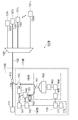
図9は、第2実施形態に係る光線路監視装置14Bを備える光線路監視システム1Bの構成を示す図である。図1に示された第1実施形態に係る光線路監視システム1Aと比較すると、この図9に示される第2実施形態に係る光線路監視システム1Bは、局舎10Aに替えて局舎10Bを備える点で相違し、局舎が光線路監視装置14Aに替えて光線路監視装置14Bを備える点で相違する。
FIG. 9 is a diagram illustrating a configuration of an optical line monitoring system 1B including the optical line monitoring apparatus 14B according to the second embodiment. Compared to the optical line monitoring system 1A according to the first embodiment shown in FIG. 1, the optical line monitoring system 1B according to the second embodiment shown in FIG. 9 replaces the station building 10A with the station building 10B. It differs in the point provided, and it differs in that the station is provided with an optical line monitoring device 14B instead of the optical line monitoring device 14A.
また、図1中の光線路監視装置14Aの構成と比較すると、図9中の光線路監視装置14Bは、OCDR測定部15およびOTDR測定部16に替えてOCDR/OTDR測定部15Bを備える点で相異する。また、図1中のOCDR測定部15の構成と比較すると、図9中のOCDR/OTDR測定部15Bは、光スイッチ66およびAD変換器67を備える点で相違する。
Compared to the configuration of the optical line monitoring device 14A in FIG. 1, the optical line monitoring device 14B in FIG. 9 includes an OCDR / OTDR measurement unit 15B instead of the OCDR measurement unit 15 and the OTDR measurement unit 16. It ’s different. 1 is different from the configuration of the OCDR measurement unit 15 in FIG. 1 in that the OCDR / OTDR measurement unit 15B in FIG. 9 includes an optical switch 66 and an AD converter 67.
光スイッチ66は、光分岐器43と偏波変調器46との間に設けられていて、光分岐器43から分岐されて出力される光の通過/遮断を行う。AD変換器67は、バランス検波器52から出力される電気信号(アナログ信号)をデジタル信号に変換して、このデジタル信号を制御部61へ出力する。
The optical switch 66 is provided between the optical branching device 43 and the polarization modulator 46, and passes / blocks the light branched from the optical branching device 43 and output. The AD converter 67 converts the electric signal (analog signal) output from the balance detector 52 into a digital signal and outputs the digital signal to the control unit 61.
OCDR/OTDR測定部15Bは、OCDR測定およびOTDR測定の双方を行うことができる。OCDR/OTDR測定部15BがOCDR測定を行う場合、光スイッチ66は開通状態とされる。OCDR/OTDR測定部15Bのその他の構成要素は図1中のOCDR測定部15と同じように動作して、OCDR測定を実現する。
The OCDR / OTDR measurement unit 15B can perform both OCDR measurement and OTDR measurement. When the OCDR / OTDR measurement unit 15B performs OCDR measurement, the optical switch 66 is opened. The other components of the OCDR / OTDR measurement unit 15B operate in the same manner as the OCDR measurement unit 15 in FIG. 1 to realize OCDR measurement.
OCDR/OTDR測定部15BがOTDR測定を行う場合、光スイッチ66は遮断状態とされ、光分岐器43から分岐されて出力される光はバランス検波器52に入力されない。信号発生器62はパルス信号を出力し、そのパルス信号が入力された光源41はパルス状の監視光を出力する。光強度変調器42および監視光ゲート部44は開通状態とされ、光源41から出力されたパルス状の監視光は、そのまま光強度変調器42および監視光ゲート部44を通過する。
When the OCDR / OTDR measurement unit 15B performs OTDR measurement, the optical switch 66 is turned off, and the light branched and output from the optical splitter 43 is not input to the balance detector 52. The signal generator 62 outputs a pulse signal, and the light source 41 to which the pulse signal is input outputs pulsed monitoring light. The light intensity modulator 42 and the monitoring light gate unit 44 are opened, and the pulsed monitoring light output from the light source 41 passes through the light intensity modulator 42 and the monitoring light gate unit 44 as they are.
或いは、光源41から連続光を出力させ光強度変調器42または監視光ゲート部44で光強度を変調することでパルス状の監視光を発生させても良い。後者の場合、光源41において周波数変調を行って光スペクトルを拡散させることにより、光線路中での誘導ブリルアン散乱の発生を抑制し、より高いパワーの監視光を光線路に送出することが可能となる。その結果、測定のSN比が改善されるとともに、測定距離が延伸され、許容される光線路損失の拡大が実現され得る。
Alternatively, pulsed monitoring light may be generated by outputting continuous light from the light source 41 and modulating the light intensity by the light intensity modulator 42 or the monitoring light gate unit 44. In the latter case, by performing frequency modulation in the light source 41 and diffusing the optical spectrum, it is possible to suppress the occurrence of stimulated Brillouin scattering in the optical line, and to send higher-power monitoring light to the optical line. Become. As a result, the SN ratio of the measurement is improved, the measurement distance is extended, and the allowable optical line loss can be increased.
監視光は、光サーキュレータ45および光結合器12を経て測定対象のPONシステム(第1の光線路32、光分岐器20,第2の光線路33n、光フィルタ22n)に送出され、測定対象中で発生した反射光は、光結合器12および光サーキュレータ45を経てバランス検波器52に達する。バランス検波器52は、OTDR測定の場合は、非バランス動作し、反射光パワーに比例した電気信号を出力する。バランス検波器52から出力された電気信号は2分岐され、一方は第1フィルタ53等を経てAD変換器57へ出力され、他方はAD変換器67へ出力される。このうちAD変換器67からの出力が制御部61によって読み取られ、OTDR測定結果として記憶される。
The monitoring light is transmitted to the PON system (first optical line 32, optical branching unit 20, second optical line 33 n , optical filter 22 n ) to be measured via the optical circulator 45 and the optical coupler 12, and measured. The reflected light generated in the object reaches the balance detector 52 through the optical coupler 12 and the optical circulator 45. In the case of OTDR measurement, the balance detector 52 performs an unbalance operation and outputs an electric signal proportional to the reflected light power. The electrical signal output from the balance detector 52 is branched into two, one being output to the AD converter 57 via the first filter 53 and the other being output to the AD converter 67. Among these, the output from the AD converter 67 is read by the control unit 61 and stored as an OTDR measurement result.
以上のようにしてOCDR/OTDR測定部15Bにより取得されたOCDR測定結果およびOTDR測定結果は、制御部17において、第1実施形態における処理と同様に処理される。
The OCDR measurement result and the OTDR measurement result acquired by the OCDR / OTDR measurement unit 15B as described above are processed in the control unit 17 in the same manner as in the first embodiment.
このように、本実施形態では、OTDR測定およびOCDR測定における光源部および検出部が共通化されている。このようにすることにより、共通化しない場合に比べて、光源波長のバラツキおよび検出部の感度のバラツキによって生じるOTDR測定結果とOCDR測定結果と間の不整合が低減され得る。このような不整合は、第1実施形態で説明したインパルス応答の補正処理では除去され得ず、測定結果の不連続性の原因となる。これに対して、本実施形態のように光源部および検出部を共通化することによって、そのような不連続性が低減され、光線路中の特徴点の誤検出が低減され得る。
Thus, in this embodiment, the light source unit and the detection unit in the OTDR measurement and the OCDR measurement are shared. By doing so, incompatibility between the OTDR measurement result and the OCDR measurement result caused by the variation in the light source wavelength and the variation in the sensitivity of the detection unit can be reduced as compared with the case where they are not shared. Such inconsistencies cannot be removed by the impulse response correction processing described in the first embodiment, and cause discontinuities in the measurement results. On the other hand, by sharing the light source unit and the detection unit as in the present embodiment, such discontinuity can be reduced, and erroneous detection of feature points in the optical line can be reduced.
(第3実施形態)
(Third embodiment)
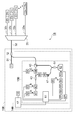
図10は、第3実施形態に係る光通信システム101Aおよび光反射測定装置113Aの構成図である。この図に示される光通信システム101Aは、局舎110Aに設けられた局側端末111とN個の加入者端末1211~121Nとが光分岐器120を介して互いに光ファイバ線路により光学的に接続されていて、局側端末111と各加入者端末121nとの間で光通信を行うものである。ここで、Nは2以上の整数であり、nは1以上N以下の各整数である。このような光通信システム101Aの形態は、PON(Passive Optical Network)と呼ばれる。分岐数Nは4~32が典型的である。
FIG. 10 is a configuration diagram of the optical communication system 101A and the light reflection measuring apparatus 113A according to the third embodiment. In the optical communication system 101A shown in this figure, a station-side terminal 111 and N subscriber terminals 121 1 to 121 N provided in a station 110A are optically connected to each other via an optical branching unit 120 via an optical fiber line. And performs optical communication between the station-side terminal 111 and each subscriber terminal 121 n . Here, N is an integer of 2 or more, and n is an integer of 1 or more and N or less. Such a form of the optical communication system 101A is called a PON (Passive Optical Network). The number of branches N is typically 4 to 32.
局舎110Aには、局側端末111の他に光結合器112および光反射測定装置113Aが設けられている。局側端末111と光結合器112とは光ファイバ線路131により光学的に接続されている。光結合器112と光分岐器120とは光ファイバ線路132により光学的に接続されている。光分岐器120と各加入者端末121nとは光ファイバ線路133nにより光学的に接続されている。また、光結合器112には光反射測定装置113Aも光学的に接続されている。
In addition to the station-side terminal 111, the station 110A is provided with an optical coupler 112 and a light reflection measuring device 113A. The station side terminal 111 and the optical coupler 112 are optically connected by an optical fiber line 131. The optical coupler 112 and the optical branching device 120 are optically connected by an optical fiber line 132. The optical branching device 120 and each subscriber terminal 121 n are optically connected by an optical fiber line 133 n . The optical coupler 112 is also optically connected with a light reflection measuring device 113A.
光反射測定装置113Aは、OCDR測定およびOTDR測定の双方を行うことができ、OCDR測定結果とOTDR測定結果とを組み合わせて出力する。光反射測定装置113Aは、光源部140A,測定部160Aおよび処理部170を備え、更に光変調器151および光遅延線152を備える。
The light reflection measuring device 113A can perform both OCDR measurement and OTDR measurement, and outputs a combination of the OCDR measurement result and the OTDR measurement result. The light reflection measurement device 113A includes a light source unit 140A, a measurement unit 160A, and a processing unit 170, and further includes an optical modulator 151 and an optical delay line 152.
光源部140Aは、光周波数が変調されて櫛歯状の光波コヒーレンス関数を有する第1監視光およびパルス状の第2監視光の何れかを選択して光結合器112へ出力する。また、光源部140Aは、第1監視光の一部を分岐して参照光として光変調器151へ出力する。第1監視光および参照光はOCDR測定に用いられ、第2監視光はOTDR測定に用いられる。光源部140Aは、光源141,信号発生器142,光変調器143および光結合器144を含む。
The light source unit 140A selects either the first monitoring light or the second monitoring light having a comb-like light wave coherence function whose optical frequency is modulated and outputs the selected light to the optical coupler 112. In addition, the light source unit 140A branches a part of the first monitoring light and outputs it as a reference light to the optical modulator 151. The first monitoring light and the reference light are used for OCDR measurement, and the second monitoring light is used for OTDR measurement. The light source unit 140 </ b> A includes a light source 141, a signal generator 142, an optical modulator 143, and an optical coupler 144.
光源部140Aに含まれる光源141は、出力光の光周波数を変調することができるものであって、例えば半導体DFBレーザ光源や外部共振器付き半導体レーザ光源等である。光源141は連続光を出力する。信号発生器142は、光源141から出力される連続光の光周波数を変調するための変調信号を出力し、その変調信号を光源141に与える。光変調器143は、光源141から出力される光を入力して、この光を必要に応じて変調して出力する。光結合器144は、光変調器143から出力される光を2分岐して、一方の分岐光を光結合器112へ出力し、他方の分岐光を光変調器151へ出力する。
The light source 141 included in the light source unit 140A can modulate the optical frequency of output light, and is, for example, a semiconductor DFB laser light source or a semiconductor laser light source with an external resonator. The light source 141 outputs continuous light. The signal generator 142 outputs a modulation signal for modulating the optical frequency of the continuous light output from the light source 141, and provides the modulation signal to the light source 141. The light modulator 143 receives light output from the light source 141, modulates the light as necessary, and outputs the modulated light. The optical coupler 144 bifurcates the light output from the optical modulator 143, outputs one branched light to the optical coupler 112, and outputs the other branched light to the optical modulator 151.
測定部160Aは、光源部140Aから出力された第1監視光が測定対象物を伝搬する際に生じる反射光および光源部140Aから出力される参照光に基づいてOCDR測定結果を取得する。また、測定部160Aは、光源部140Aから出力された第2監視光が測定対象物を伝搬する際に生じる反射光に基づいてOTDR測定結果を取得する。測定部160Aは、光結合器161,バランス検波器162,フィルタ163,RF検波器164,AD変換器165およびAD変換器166を含む。
The measurement unit 160A acquires the OCDR measurement result based on the reflected light generated when the first monitoring light output from the light source unit 140A propagates through the measurement target and the reference light output from the light source unit 140A. In addition, the measurement unit 160A acquires the OTDR measurement result based on the reflected light generated when the second monitoring light output from the light source unit 140A propagates through the measurement target. The measurement unit 160A includes an optical coupler 161, a balance detector 162, a filter 163, an RF detector 164, an AD converter 165, and an AD converter 166.
測定部160Aに含まれる光結合器161は、光結合器144から出力される光を入力するとともに、光遅延線152から光が出力される場合にはその光をも入力して、その入力した光をバランス検波器162へ出力する。バランス検波器162は、光結合器161から出力される光を入力して検波し、その検波結果を表す電気信号をフィルタ163またはAD変換器166へ出力する。フィルタ163は、バランス検波器162から出力される電気信号を入力し、その電気信号に含まれる雑音成分を除去して、その除去後の電気信号をRF検波器164へ出力する。
The optical coupler 161 included in the measurement unit 160A inputs the light output from the optical coupler 144, and also inputs the light when the light is output from the optical delay line 152. The light is output to the balance detector 162. The balance detector 162 receives and detects the light output from the optical coupler 161, and outputs an electrical signal representing the detection result to the filter 163 or the AD converter 166. The filter 163 receives the electrical signal output from the balance detector 162, removes noise components included in the electrical signal, and outputs the electrical signal after the removal to the RF detector 164.
測定部160Aに含まれるRF検波器164は、フィルタ163から出力される電気信号を入力し、干渉成分の大きさに相当する電気信号に変換してAD変換器165へ出力する。AD変換器165は、RF検波器164から出力される電気信号を入力し、この電気信号(アナログ信号)をデジタル信号に変換して、このデジタル信号(OCDR測定結果)を処置部170へ出力する。また、AD変換器166は、バランス検波器162から出力される電気信号を入力し、この電気信号(アナログ信号)をデジタル信号に変換して、このデジタル信号(OTDR測定結果)を処置部170へ出力する。
The RF detector 164 included in the measurement unit 160A receives the electrical signal output from the filter 163, converts the electrical signal into an electrical signal corresponding to the magnitude of the interference component, and outputs the electrical signal to the AD converter 165. The AD converter 165 receives the electrical signal output from the RF detector 164, converts the electrical signal (analog signal) into a digital signal, and outputs the digital signal (OCDR measurement result) to the treatment unit 170. . Further, the AD converter 166 receives the electrical signal output from the balance detector 162, converts the electrical signal (analog signal) into a digital signal, and converts the digital signal (OTDR measurement result) to the treatment unit 170. Output.
なお、OCDR測定の際には、AD変換器166は用いられない。また、OTDR測定の際には、フィルタ163,RF検波器164およびAD変換器165は用いられない。
Note that the AD converter 166 is not used in the OCDR measurement. Further, the filter 163, the RF detector 164, and the AD converter 165 are not used in the OTDR measurement.
処理部170は、測定部160Aにより取得されたOCDR測定結果とOTDR測定結果とを組み合わせて出力する。また、処理部170は、OCDR測定結果とOTDR測定結果とに基づいて所定の演算を行って、その演算結果を出力する。処理部170は、制御部171および記憶部172を含む。
The processing unit 170 outputs a combination of the OCDR measurement result and the OTDR measurement result acquired by the measurement unit 160A. The processing unit 170 performs a predetermined calculation based on the OCDR measurement result and the OTDR measurement result, and outputs the calculation result. The processing unit 170 includes a control unit 171 and a storage unit 172.
処理部170に含まれる制御部171は、光源部140Aの動作を制御する。また、制御部171は、AD変換器165から出力されるデジタル信号(OCDR測定結果)を入力するとともに、AD変換器166から出力されるデジタル信号(OTDR測定結果)を入力して、これらOCDR測定結果およびOTDR測定結果を記憶部172に記憶させる。記憶部172は、第2監視光のパルス時間波形を予め記憶している。そして、制御部171は、OCDR測定結果,OTDR測定結果および第2監視光のパルス時間波形に基づいて所定の演算を行って、その演算結果を出力する。
The control unit 171 included in the processing unit 170 controls the operation of the light source unit 140A. In addition, the control unit 171 receives the digital signal (OCDR measurement result) output from the AD converter 165 and the digital signal (OTDR measurement result) output from the AD converter 166, and performs these OCDR measurements. The result and the OTDR measurement result are stored in the storage unit 172. The storage unit 172 stores a pulse time waveform of the second monitoring light in advance. Then, the control unit 171 performs a predetermined calculation based on the OCDR measurement result, the OTDR measurement result, and the pulse time waveform of the second monitoring light, and outputs the calculation result.
次に、OCDR測定について説明する。OCDR測定の場合、光源部140Aは、光周波数が変調されて櫛歯状の光波コヒーレンス関数を有する第1監視光を出力する。このとき、光源141から出力される連続光は、信号発生器142により光周波数が変調されて、櫛歯状の光波コヒーレンス関数を有するものとされる。具体例としては、光周波数を一定時間間隔で順にf0,f0+fs,f0-fs,f0+2fs,f0-2fs,f0+3fs,f0-3fs,・・・ というように変調された光が第1監視光として用いられる。或いは、変調周波数fsで光周波数が正弦波状に変調された光が第1監視光として用いられる。このように光周波数が変調された第1監視光の光波コヒーレンス関数は、fsτが整数であるときにデルタ関数形状に類似した形状のピーク(コヒーレンスピーク)を有する。すなわち、これらの第1監視光は、櫛歯状の光波コヒーレンス関数を有する。fsが変化すると、コヒーレンスピークの位置も変化する。
Next, OCDR measurement will be described. In the case of the OCDR measurement, the light source unit 140A outputs the first monitoring light having a comb-like lightwave coherence function with the optical frequency modulated. At this time, the continuous light output from the light source 141 is modulated in optical frequency by the signal generator 142 and has a comb-like optical wave coherence function. As a specific example, the optical frequencies are sequentially set to f 0 , f 0 + f s , f 0 −f s , f 0 + 2f s , f 0 −2f s , f 0 + 3f s , f 0 −3f s ,. .. The modulated light is used as the first monitoring light. Alternatively, light whose optical frequency is modulated in a sine wave shape at the modulation frequency f s is used as the first monitoring light. The optical coherence function of the first monitoring light whose optical frequency is modulated in this way has a peak (coherence peak) having a shape similar to the delta function shape when f s τ is an integer. That is, these first monitoring lights have a comb-like light wave coherence function. As f s changes, the position of the coherence peak also changes.
光変調器143は、光源141から出力される連続光を光周波数変調に同期して強度変調して、この強度変調した光を第1監視光として出力するのが好適である。このような第1監視光は、光波コヒーレンス関数のサイドローブが抑圧されたものとなる。そして、光結合器144は、光変調器143から出力された第1監視光を光結合器112へ出力するとともに、第1監視光の一部を分岐して参照光として光変調器151へ出力する。
The optical modulator 143 preferably modulates the intensity of the continuous light output from the light source 141 in synchronization with the optical frequency modulation, and outputs the intensity-modulated light as the first monitoring light. Such first monitoring light is one in which the side lobe of the lightwave coherence function is suppressed. Then, the optical coupler 144 outputs the first monitoring light output from the optical modulator 143 to the optical coupler 112 and branches a part of the first monitoring light to output to the optical modulator 151 as reference light. To do.
光結合器144から光結合器112へ出力された第1監視光は、光ファイバ線路132,光分岐器120および光ファイバ線路133nを経て加入者端末121nへ伝搬する。第1監視光が測定対象物(光ファイバ線路132,光分岐器120,光ファイバ線路133n,加入者端末121n)を伝搬する際に、測定対象物上の離散反射点においてフレネル反射光が生じ、また、離散反射点の間の区間においてレイリー散乱光が生じる。これら反射光(フレネル反射光、レイリー散乱光)は、光結合器112および光結合器144を経て光結合器161へ入力される。
The first monitoring light output from the optical coupler 144 to the optical coupler 112 propagates to the subscriber terminal 121 n via the optical fiber line 132, the optical branching unit 120, and the optical fiber line 133 n . When the first monitoring light propagates through the measurement object (optical fiber line 132, optical branching device 120, optical fiber line 133 n , subscriber terminal 121 n ), Fresnel reflected light is reflected at discrete reflection points on the measurement object. And Rayleigh scattered light occurs in the section between the discrete reflection points. These reflected lights (Fresnel reflected light and Rayleigh scattered light) are input to the optical coupler 161 through the optical coupler 112 and the optical coupler 144.
一方、光結合器144から光変調器151へ出力された参照光は、光変調器151および光遅延線152を経て光結合器161へ入力される。光変調器151は、光結合器144から出力される参照光を入力し、必要に応じて、所定のタイミングで参照光にゲートをかけることで、OCDR測定の際の測定対象物における被測定位置を決定する。光遅延線152は、光変調器151から出力される参照光に対して遅延を与えることで、光結合器161に入力される第1監視光の反射光と参照光との光路長差を小さくして、光源141から出力される光の位相揺らぎによって生じる雑音を低減する。
On the other hand, the reference light output from the optical coupler 144 to the optical modulator 151 is input to the optical coupler 161 via the optical modulator 151 and the optical delay line 152. The optical modulator 151 receives the reference light output from the optical coupler 144, and gates the reference light at a predetermined timing as necessary, thereby measuring the position to be measured in the object to be measured in the OCDR measurement. To decide. The optical delay line 152 reduces the optical path length difference between the reflected light of the first monitoring light input to the optical coupler 161 and the reference light by delaying the reference light output from the optical modulator 151. Thus, noise generated by the phase fluctuation of the light output from the light source 141 is reduced.
なお、光変調器151は、参照光に対してゲートをかけることの他、参照光を偏波変調してもよいし、参照光の光周波数をシフトさせてもよいし、これらのうちの複数の処理をしてもよい。参照光を偏波変調して複数の偏波状態でOCDR測定結果を平均化することにより、第1監視光および参照光の偏波ゆらぎの影響を低減することができる。また、参照光の光周波数をシフトさせて第1監視光の反射光がヘテロダイン検波されるようにすることで、第1監視光の強度ゆらぎによる雑音を低減することができる。
Note that the optical modulator 151 may perform polarization modulation of the reference light, shift the optical frequency of the reference light, or may apply a plurality of the reference light, in addition to gating the reference light. May be processed. By polarization-modulating the reference light and averaging the OCDR measurement results in a plurality of polarization states, the influence of the polarization fluctuations of the first monitoring light and the reference light can be reduced. Further, by shifting the optical frequency of the reference light so that the reflected light of the first monitoring light is subjected to heterodyne detection, noise due to intensity fluctuation of the first monitoring light can be reduced.
光結合器161は、光結合器144から出力される第1監視光の反射光と光遅延線152から出力される参照光とを結合して、これらをバランス検波器162へ出力する。バランス検波器162は、これら反射光と参照光とを入力してバランス検波して、これら反射光および参照光それぞれの電界の干渉成分に相当する電気信号をフィルタ163へ出力する。フィルタ163は、バランス検波器162から出力される電気信号を入力し、その電気信号に含まれる雑音成分を除去して、その除去後の電気信号をRF検波器164へ出力する。
The optical coupler 161 combines the reflected light of the first monitoring light output from the optical coupler 144 and the reference light output from the optical delay line 152, and outputs these to the balance detector 162. The balance detector 162 receives the reflected light and the reference light, performs balance detection, and outputs an electric signal corresponding to the interference component of the electric field of each of the reflected light and the reference light to the filter 163. The filter 163 receives the electrical signal output from the balance detector 162, removes noise components included in the electrical signal, and outputs the electrical signal after the removal to the RF detector 164.
RF検波器164は、フィルタ163から出力される電気信号を入力し、干渉成分の大きさに相当する電気信号に変換してAD変換器165へ出力する。AD変換器165は、RF検波器164から出力される電気信号を入力し、この電気信号をデジタル信号に変換して、このデジタル信号を制御部171へ出力する。制御部171は、AD変換器165から出力されたデジタル信号を入力して、このデジタル信号を記憶部172により記憶させる。このデジタル信号の値は、測定対象物における被測定位置での反射率を表す。
The RF detector 164 receives the electrical signal output from the filter 163, converts the electrical signal into an electrical signal corresponding to the magnitude of the interference component, and outputs the electrical signal to the AD converter 165. The AD converter 165 receives the electrical signal output from the RF detector 164, converts the electrical signal into a digital signal, and outputs the digital signal to the control unit 171. The control unit 171 receives the digital signal output from the AD converter 165 and causes the storage unit 172 to store the digital signal. The value of this digital signal represents the reflectance at the measurement position in the measurement object.
さらに、制御部171による制御に従って、光源141における光周波数変調の際のパラメータfsが変更されることにより、コヒーレンスピークの位置(すなわち、測定対象物における被測定位置)が変更されて、上記と同様にして、測定対象物における被測定位置での反射率を表すデジタル信号が記憶部172により記憶される。コヒーレンスピークの位置(すなわち、測定対象物における被測定位置)が走査されることで、OCDR測定結果が得られる。
Furthermore, the position of the coherence peak (that is, the position to be measured in the measurement object) is changed by changing the parameter f s at the time of optical frequency modulation in the light source 141 according to control by the control unit 171, and Similarly, the storage unit 172 stores a digital signal representing the reflectance at the measurement position on the measurement object. The OCDR measurement result is obtained by scanning the position of the coherence peak (that is, the position to be measured in the measurement object).
次に、OTDR測定について説明する。OTDR測定の場合、光源部140Aは、パルス状の第2監視光を出力する。このとき、光変調器143は、光源141から出力される連続光を強度変調して、パルス状の第2監視光として出力する。このとき、光源141は、信号発生器142から出力される変調信号に従って光周波数を変調して、スペクトル拡散された連続光を出力するのが好適である。このように第2監視光のスペクトルが拡散されることで、光ファイバ線路132,1331~33Nを第2監視光が伝搬する際に誘導ブリルアン散乱などの非線形光学現象の発生が抑制される。そして、光結合器144は、光変調器143から出力された第2監視光を光結合器112へ出力するとともに、第2監視光の一部を分岐して光変調器151へ出力する。光変調器151へ出力された光は、この光変調器151により遮断される。
Next, OTDR measurement will be described. In the case of OTDR measurement, the light source unit 140A outputs pulsed second monitoring light. At this time, the optical modulator 143 modulates the intensity of the continuous light output from the light source 141 and outputs it as pulsed second monitoring light. At this time, it is preferable that the light source 141 modulates the optical frequency in accordance with the modulation signal output from the signal generator 142 and outputs the spectrum-spread continuous light. By spreading the spectrum of the second monitoring light in this way, the occurrence of nonlinear optical phenomena such as stimulated Brillouin scattering when the second monitoring light propagates through the optical fiber lines 132 and 133 1 to 33 N is suppressed. . Then, the optical coupler 144 outputs the second monitoring light output from the optical modulator 143 to the optical coupler 112 and branches a part of the second monitoring light to output it to the optical modulator 151. The light output to the optical modulator 151 is blocked by the optical modulator 151.
光結合器144から光結合器112へ出力された第2監視光は、光ファイバ線路132,光分岐器120および光ファイバ線路133nを経て加入者端末121nへ伝搬する。第2監視光が測定対象物(光ファイバ線路132,光分岐器120,光ファイバ線路133n,加入者端末121n)を伝搬する際に、測定対象物上の離散反射点においてフレネル反射光が生じ、また、離散反射点の間の区間においてレイリー散乱光が生じる。これら反射光(フレネル反射光、レイリー散乱光)は、光結合器112および光結合器144を経て光結合器161へ入力される。
The second monitoring light output from the optical coupler 144 to the optical coupler 112 propagates to the subscriber terminal 121 n via the optical fiber line 132, the optical branching unit 120, and the optical fiber line 133 n . When the second monitoring light propagates through the measurement object (optical fiber line 132, optical branching device 120, optical fiber line 133 n , subscriber terminal 121 n ), Fresnel reflected light is reflected at discrete reflection points on the measurement object. And Rayleigh scattered light occurs in the section between the discrete reflection points. These reflected lights (Fresnel reflected light and Rayleigh scattered light) are input to the optical coupler 161 through the optical coupler 112 and the optical coupler 144.
光結合器161は、光結合器144から出力される第2監視光の反射光を入力して、これをバランス検波器162へ出力する。バランス検波器162は、非バランス動作を行い、光結合器161から出力される光を入力して、この入力光パワーに応じた電気信号をAD変換器166へ出力する。この電気信号を時間の関数としたものが、測定対象物における反射率分布をあらわす。AD変換器166は、バランス検波器162から出力される電気信号を入力し、この電気信号を一定時間間隔でデジタル信号に変換して、このデジタル信号を制御部171へ出力する。制御部171は、AD変換器166から出力されたデジタル信号を入力して、このデジタル信号を記憶部172により記憶させる。このようにして、OTDR測定結果が得られる。
The optical coupler 161 receives the reflected light of the second monitoring light output from the optical coupler 144 and outputs it to the balance detector 162. The balance detector 162 performs an unbalance operation, inputs light output from the optical coupler 161, and outputs an electrical signal corresponding to the input optical power to the AD converter 166. This electrical signal as a function of time represents the reflectance distribution in the measurement object. The AD converter 166 receives the electric signal output from the balance detector 162, converts the electric signal into a digital signal at regular time intervals, and outputs the digital signal to the control unit 171. The control unit 171 receives the digital signal output from the AD converter 166 and causes the storage unit 172 to store the digital signal. In this way, an OTDR measurement result is obtained.
次に、図11および図12を用いて、処理部170における処理の内容について説明する。図11は、OCDR測定結果,OTDR測定結果および処理部170の処理結果それぞれを模式的に示す図である。図12は、処理部170の処理のフローを示す図である。処理部170に含まれる制御部171は、以上のようにして得られて記憶部172により記憶されているOCDR測定結果およびOTDR測定結果、ならびに、記憶部172により予め記憶されている第2監視光のパルス時間波形を用いて、以下のような処理を行う。
Next, the contents of processing in the processing unit 170 will be described with reference to FIGS. 11 and 12. FIG. 11 is a diagram schematically illustrating the OCDR measurement result, the OTDR measurement result, and the processing result of the processing unit 170. FIG. 12 is a diagram illustrating a processing flow of the processing unit 170. The control unit 171 included in the processing unit 170 includes the OCDR measurement result and the OTDR measurement result obtained as described above and stored in the storage unit 172, and the second monitoring light stored in advance in the storage unit 172. The following processing is performed using the pulse time waveform.
図11に示されるように、一般に、OCDR測定結果によれば、離散的な反射点の位置(例えば光ファイバ線路133nと加入者端末121nとの接続点)が高い空間分解能で得られるが、これらの反射点の間の区間では光波コヒーレンス関数のサイドローブに起因するコヒーレンスノイズが観測されるので当該区間での情報が得られない。一方、OTDR測定結果によれば、離散的な反射点の間の区間ではレイリー散乱光が観測されるが、これら反射点の付近では反射点位置と第2監視光のパルス時間波形との畳み込みに因るブロードなピークが観測される。
As shown in FIG. 11, generally, according to the OCDR measurement result, the position of the discrete reflection point (for example, the connection point between the optical fiber line 133 n and the subscriber terminal 121 n ) can be obtained with high spatial resolution. In the section between these reflection points, coherence noise due to the side lobe of the light wave coherence function is observed, so information in the section cannot be obtained. On the other hand, according to the OTDR measurement results, Rayleigh scattered light is observed in the section between the discrete reflection points, but in the vicinity of these reflection points, the reflection point position and the pulse time waveform of the second monitoring light are convoluted. A broad peak is observed.
そこで、このようなOCDR測定結果およびOTDR測定結果それぞれの特質を考慮して、本実施形態に係る光反射測定装置113Aの処理部170は、OCDR測定結果,OTDR測定結果および第2監視光のパルス時間波形を用いて図12に示される処理を行うことにより、図11に示されるようなレイリー散乱光測定を含んだ高分解能の反射点測定結果を得る。
Therefore, in consideration of the respective characteristics of the OCDR measurement result and the OTDR measurement result, the processing unit 170 of the light reflection measurement apparatus 113A according to the present embodiment performs the OCDR measurement result, the OTDR measurement result, and the pulse of the second monitoring light. By performing the processing shown in FIG. 12 using the time waveform, a high-resolution reflection point measurement result including the Rayleigh scattered light measurement as shown in FIG. 11 is obtained.
処理部170に含まれる制御部171は、先ず、記憶部172に記憶されているOCDR測定結果を用い、コヒーレンスノイズより高い所定の水準でOCDR測定結果の閾値処理を行ってピーク位置を検出することにより、測定対象物における離散反射点の位置のリストを求める。
First, the control unit 171 included in the processing unit 170 uses the OCDR measurement result stored in the storage unit 172 to detect the peak position by performing threshold processing of the OCDR measurement result at a predetermined level higher than the coherence noise. Thus, a list of positions of discrete reflection points in the measurement object is obtained.
また、制御部171は、記憶部172に記憶されている第2監視光のパルス時間波形、および、測定対象物の波長分散や偏波モ-ド分散の長手方向分布などの情報を用いて、測定対象物を第2監視光が伝搬する際のパルス拡がりに因る各位置での第2監視光のパルス時間波形を求める。
Further, the control unit 171 uses information such as the pulse time waveform of the second monitoring light stored in the storage unit 172 and the longitudinal distribution of the chromatic dispersion and polarization mode dispersion of the measurement object, A pulse time waveform of the second monitoring light at each position due to the pulse spread when the second monitoring light propagates through the measurement object is obtained.
さらに、制御部171は、既に求めた離散反射点の位置リストと各位置での第2監視光のパルス時間波形とを畳み込み演算することにより、離散反射点での第2監視光の反射によるOTDR測定結果への寄与の程度を求める。
Further, the control unit 171 performs a convolution operation on the already obtained position list of the discrete reflection points and the pulse time waveform of the second monitoring light at each position, thereby performing OTDR due to the reflection of the second monitoring light at the discrete reflection points. Obtain the degree of contribution to the measurement results.
そして、制御部171は、この求めた寄与の程度に基づいて、記憶部172に記憶されているOTDR測定結果を補正して、その補正結果を出力する。具体的には、制御部171は、離散反射点での第2監視光の反射によるOTDR測定結果への寄与をOTDR測定結果から減算し、離散反射点の位置リストからデルタ関数状の反射ピーク波形を生成して、これを上記の減算の結果に対して合成する。
And the control part 171 correct | amends the OTDR measurement result memorize | stored in the memory | storage part 172 based on the calculated | required degree of contribution, and outputs the correction result. Specifically, the control unit 171 subtracts the contribution to the OTDR measurement result due to the reflection of the second monitoring light at the discrete reflection point from the OTDR measurement result, and reflects the delta function-like reflection peak waveform from the position list of the discrete reflection point. Is combined with the result of the above subtraction.
このような処理を処理部170が行うことで、本実施形態に係る光反射測定装置113Aは、測定対象物において発生するレイリー散乱光および離散的な反射光を高精度に検出することができ、高分解能の反射率分布の測定結果を得ることができる。
By performing such processing by the processing unit 170, the light reflection measuring apparatus 113A according to the present embodiment can detect Rayleigh scattered light and discrete reflected light generated in the measurement object with high accuracy, A measurement result of the reflectance distribution with high resolution can be obtained.
(第4実施形態)
(Fourth embodiment)
図13は、第4実施形態に係る光通信システム101Bおよび光反射測定装置113Bの構成図である。図10に示された第3実施形態に係る光通信システム101Aの構成と比較すると、この図13に示される第4実施形態に係る光通信システム101Bは、局舎110Aに替えて局舎110Bを備える点で相違し、光反射測定装置113Aに替えて光反射測定装置113Bを備える点で相違する。
FIG. 13 is a configuration diagram of the optical communication system 101B and the light reflection measuring apparatus 113B according to the fourth embodiment. Compared to the configuration of the optical communication system 101A according to the third embodiment shown in FIG. 10, the optical communication system 101B according to the fourth embodiment shown in FIG. 13 has a station 110B instead of the station 110A. It differs in the point provided, and it differs in the point provided with the light reflection measuring device 113B instead of the light reflection measuring device 113A.
また、図10中の光反射測定装置113Aの構成と比較すると、図13中の光反射測定装置113Bは、光源部140Aに替えて光源部140Bを含む点で相違し、測定部160Aに替えて測定部160Bを含む点で相違し、また、光サーキュレータ153を更に含む点で相違する。
Compared with the configuration of the light reflection measuring device 113A in FIG. 10, the light reflection measuring device 113B in FIG. 13 is different in that it includes a light source unit 140B instead of the light source unit 140A, and instead of the measurement unit 160A. The difference is that the measurement unit 160B is included, and that the optical circulator 153 is further included.
光源部140Bは、光源141,信号発生器142,光変調器143および光結合器144を含む。光結合器144は、光源141と光変調器143との間に設けられ、光源141から出力される第1監視光および第2監視光それぞれを2分岐して、一方の分岐光を光変調器143へ出力し、他方の分岐光を光変調器151へ出力する。光変調器143は、光結合器144から出力された光を入力し、この光を変調して光サーキュレータ153へ出力する。
The light source unit 140B includes a light source 141, a signal generator 142, an optical modulator 143, and an optical coupler 144. The optical coupler 144 is provided between the light source 141 and the optical modulator 143, divides each of the first monitoring light and the second monitoring light output from the light source 141 into two, and one of the branched lights is an optical modulator. The other branched light is output to the optical modulator 151. The optical modulator 143 receives the light output from the optical coupler 144, modulates the light, and outputs the modulated light to the optical circulator 153.
光サーキュレータ153は、光変調器143から出力された光を入力して、この入力した光を光結合器112へ出力する。また、光サーキュレータ153は、光結合器112から出力された光を入力して、この入力した光を光結合器161へ出力する。
The optical circulator 153 receives the light output from the optical modulator 143 and outputs the input light to the optical coupler 112. The optical circulator 153 receives the light output from the optical coupler 112 and outputs the input light to the optical coupler 161.
測定部160Bは、光結合器161,バランス検波器162,フィルタ163,RF検波器164およびAD変換器165を含む。光結合器161は、光サーキュレータ153から出力された光を入力するとともに、光遅延線152から出力された光をも入力して、これらの光をバランス検波器162へ出力する。
The measurement unit 160B includes an optical coupler 161, a balance detector 162, a filter 163, an RF detector 164, and an AD converter 165. The optical coupler 161 receives the light output from the optical circulator 153 and also receives the light output from the optical delay line 152, and outputs these lights to the balance detector 162.
OCDR測定の場合、光源141から出力された第1監視光は、光結合器144,光変調器143,光サーキュレータ153および光結合器112を経て、測定対象物(光ファイバ線路132,光分岐器120,光ファイバ線路133n,加入者端末121n)を伝搬する。この伝搬の際に生じる反射光(フレネル反射光、レイリー散乱光)は、光結合器112および光サーキュレータ153を経て光結合器161へ入力される。また、光源141から出力された第1監視光の一部は光結合器144により分岐されて参照光とされる。その参照光は、光変調器151および光遅延線152を経て光結合器161へ入力される。測定部160Bおよび処理部170においては、第3実施形態の場合と同様の動作が行われて、OCDR測定結果が得られる。
In the case of the OCDR measurement, the first monitoring light output from the light source 141 passes through the optical coupler 144, the optical modulator 143, the optical circulator 153, and the optical coupler 112, and then the measurement object (optical fiber line 132, optical branching device). 120, optical fiber line 133 n , subscriber terminal 121 n ). Reflected light (Fresnel reflected light, Rayleigh scattered light) generated during this propagation is input to the optical coupler 161 through the optical coupler 112 and the optical circulator 153. Further, a part of the first monitoring light output from the light source 141 is branched by the optical coupler 144 to become reference light. The reference light is input to the optical coupler 161 through the optical modulator 151 and the optical delay line 152. In the measurement unit 160B and the processing unit 170, the same operation as that in the third embodiment is performed, and an OCDR measurement result is obtained.
一方、OTDR測定の場合、光源141から出力された第2監視光は、光結合器144,光変調器143,光サーキュレータ153および光結合器112を経て、測定対象物を伝搬する。この伝搬の際に生じる反射光(フレネル反射光、レイリー散乱光)は、光結合器112および光サーキュレータ153を経て光結合器161へ入力される。また、光源141から出力された第2監視光の一部は光結合器144により分岐されて参照光とされる。その参照光は、光変調器151および光遅延線152を経て光結合器161へ入力される。
On the other hand, in the case of OTDR measurement, the second monitoring light output from the light source 141 propagates through the measurement object through the optical coupler 144, the optical modulator 143, the optical circulator 153, and the optical coupler 112. Reflected light (Fresnel reflected light, Rayleigh scattered light) generated during this propagation is input to the optical coupler 161 through the optical coupler 112 and the optical circulator 153. Further, a part of the second monitoring light output from the light source 141 is branched by the optical coupler 144 to become reference light. The reference light is input to the optical coupler 161 through the optical modulator 151 and the optical delay line 152.
本実施形態では、OTDR測定の場合にも、バランス検波器162はバランス検波動作する。望ましくは、光変調器151により参照光の光周波数がシフトされ、バランス検波器162により第2監視光がヘテロダイン検波される。その結果、コヒーレントOTDR(C-OTDR)として知られる測定方式が実現され、反射率分布が測定される。
In this embodiment, the balance detector 162 performs a balance detection operation even in the case of OTDR measurement. Desirably, the optical frequency of the reference light is shifted by the optical modulator 151, and the second monitoring light is heterodyne detected by the balance detector 162. As a result, a measurement scheme known as coherent OTDR (C-OTDR) is realized and the reflectance distribution is measured.
処理部170は、第3実施形態の場合と同様の処理をする。OCDR測定結果およびC-OTDR測定結果が図12のフローで処理されることにより、図11に示したような高分解能の反射率分布測定結果が得られる。さらに、C-OTDRでは十分に高いパワーを有する参照光を用いることによりショットノイズ限界の測定が可能であるので、32分岐システムなどの光分岐器120での挿入損失が高いPONシステムにも用いることができる。
The processing unit 170 performs the same processing as in the third embodiment. By processing the OCDR measurement result and the C-OTDR measurement result in the flow of FIG. 12, a high-resolution reflectance distribution measurement result as shown in FIG. 11 is obtained. Furthermore, since the shot noise limit can be measured by using a reference light having sufficiently high power in C-OTDR, it should also be used for a PON system having a high insertion loss in the optical branching unit 120 such as a 32-branch system. Can do.
以上、光反射測定装置は、(1) 光周波数が変調されて櫛歯状の光波コヒーレンス関数を有する第1監視光およびパルス状の第2監視光の何れかを選択して出力するとともに、第1監視光の一部を分岐して参照光として出力する光源部と、(2)光源部から出力された第1監視光が測定対象物を伝搬する際に生じる反射光および光源部から出力される参照光に基づいてOCDR測定結果を取得するとともに、光源部から出力された第2監視光が測定対象物を伝搬する際に生じる反射光に基づいてOTDR測定結果を取得する測定部と、(3)測定部により取得されたOCDR測定結果とOTDR測定結果とを組み合わせて出力する処理部と、を備えることを特徴とする。このようにしてOCDR測定結果とOTDR測定結果とが組み合わされて出力されることにより、測定対象物における離散反射点が高い空間分解能で検出されるとともに、測定対象物における離散反射点の間の区間の状態をも測定され得る。
As described above, the light reflection measuring device (1) selects and outputs either the first monitoring light or the pulsed second monitoring light having a comb-like light wave coherence function with the fluorescence frequency modulated, and the first A light source unit that branches a part of one monitoring light and outputs it as a reference light; and (2) a reflected light generated when the first monitoring light output from the light source unit propagates through the measurement object and the light source unit. A measurement unit that obtains an OCDR measurement result based on the reference light to be obtained, and obtains an OTDR measurement result based on the reflected light generated when the second monitoring light output from the light source unit propagates through the measurement object; 3) A processing unit that outputs a combination of the OCDR measurement result and the OTDR measurement result acquired by the measurement unit. Thus, the OCDR measurement result and the OTDR measurement result are combined and output, so that the discrete reflection point on the measurement object is detected with a high spatial resolution, and the interval between the discrete reflection points on the measurement object. Can also be measured.
また、光反射測定装置では、処理部は、OCDR測定結果に基づいて、測定対象物における離散反射点の位置を求め、この求めた離散反射点の位置と第2監視光のパルス時間波形とに基づいて、離散反射点での第2監視光の反射によるOTDR測定結果への寄与の程度を求め、この求めた寄与の程度に基づいてOTDR測定結果を補正して、その補正結果を出力するのが好適である。このような処理が行われることにより、測定対象物における離散反射点の付近の状態が測定されるとともに、離散反射点および離散反射点の間の区間の情報が一元化され得る。
Further, in the light reflection measurement device, the processing unit obtains the position of the discrete reflection point on the measurement object based on the OCDR measurement result, and uses the obtained position of the discrete reflection point and the pulse time waveform of the second monitoring light. Based on this, the degree of contribution to the OTDR measurement result due to the reflection of the second monitoring light at the discrete reflection point is obtained, the OTDR measurement result is corrected based on the obtained degree of contribution, and the correction result is output. Is preferred. By performing such processing, the state near the discrete reflection point in the measurement object is measured, and information on the section between the discrete reflection point and the discrete reflection point can be unified.
また、光通信システムは、光ファイバ線路により互いに光学的に接続された局側端末と加入者端末との間で光通信を行う光通信システムであって、光ファイバ線路の途中に設けられた光結合器と、この光結合器に光学的に接続された上記の光反射測定装置とを備え、光反射測定装置から選択的に出力される第1監視光または第2監視光を、光結合器を経て光ファイバ線路に伝搬させ、第1監視光または第2監視光が光ファイバ線路を伝搬する際に生じる反射光を、光結合器を経て光反射測定装置に入力させることを特徴とする。また、本発明に係る光通信システムは、局側端末と複数の加入者端末とが光分岐器を介して光学的に接続されており、局側端末と光分岐器との間の光ファイバ線路の途中に光結合器が設けられているのが好適である。このように光通信システムにおいて上記の光反射測定装置が用いられることにより、加入者端末や光ファイバ線路で生じる故障の箇所が特定され得る。
The optical communication system is an optical communication system that performs optical communication between a station-side terminal and a subscriber terminal that are optically connected to each other via an optical fiber line, and is provided in the middle of the optical fiber line. A coupler and the above-described light reflection measuring device optically connected to the optical coupler, wherein the first monitoring light or the second monitoring light selectively output from the light reflection measuring device is supplied to the optical coupler. And the reflected light generated when the first monitoring light or the second monitoring light propagates through the optical fiber line is input to the light reflection measuring device via the optical coupler. In the optical communication system according to the present invention, a station side terminal and a plurality of subscriber terminals are optically connected via an optical branching unit, and an optical fiber line between the station side terminal and the optical branching unit. It is preferable that an optical coupler is provided in the middle. As described above, by using the above-described light reflection measuring apparatus in the optical communication system, it is possible to specify the location of the failure that occurs in the subscriber terminal or the optical fiber line.
また、光通信システムは、光分岐器から複数の加入者端末それぞれまでの光ファイバ長が加入者端末毎に異なるのが好適である。この場合には、加入者端末が個別に区別され得る。
Also, in the optical communication system, it is preferable that the optical fiber length from the optical branching device to each of the plurality of subscriber terminals is different for each subscriber terminal. In this case, the subscriber terminals can be individually distinguished.
上記の光反射測定装置や光通信システムによれば、測定対象物において発生するレイリー散乱光および離散的な反射光を高精度に検出することができる。
According to the above-described light reflection measuring apparatus and optical communication system, Rayleigh scattered light and discrete reflected light generated in the measurement object can be detected with high accuracy.
(変形例)
(Modification)
本発明は、上記実施形態に限定されるものではなく、種々の変形が可能である。例えば、上記第3及び第4実施形態において、第1監視光の光波コヒーレンス関数のサイドローブを抑圧する手法を組み合わせて用いてもよい。すなわち、信号発生器142が生成する変調波形を正弦波とすると、光源141から出力される光のパワースペクトルの両端部においてスペクトル変化が急峻となるのでサイドローブが発生するが、このサイドローブを抑圧するために、光フィルタによってスペクトルの両端部を平滑化する方法や、変調波形を歪ませることでスペクトルを平滑化する方法を採用するのが好ましい。
The present invention is not limited to the above embodiment, and various modifications are possible. For example, in the said 3rd and 4th embodiment, you may use combining the method of suppressing the side lobe of the lightwave coherence function of 1st monitoring light. That is, if the modulation waveform generated by the signal generator 142 is a sine wave, side lobes are generated because the spectrum change becomes steep at both ends of the power spectrum of the light output from the light source 141, and this side lobe is suppressed. Therefore, it is preferable to employ a method of smoothing both ends of the spectrum with an optical filter or a method of smoothing the spectrum by distorting the modulation waveform.
また、上記第3及び第4実施形態において、局側端末111から出力される信号光の波長と異なる波長の監視光を用いることにより、信号光と監視光との干渉を防ぐことが望ましい。信号光波長としては1.3μm帯,1.49μm帯および1.55μm帯などが用いられるので、第1監視光または第2監視光の波長としては1.58~1.65μm帯が好ましい。また、光結合器112は、波長合波器として信号光および監視光の挿入損失を最小限に抑えることが好ましい。
In the third and fourth embodiments, it is desirable to prevent interference between the signal light and the monitoring light by using the monitoring light having a wavelength different from the wavelength of the signal light output from the station-side terminal 111. As the signal light wavelength, the 1.3 μm band, the 1.49 μm band, the 1.55 μm band, and the like are used. Therefore, the wavelength of the first monitoring light or the second monitoring light is preferably the 1.58 to 1.65 μm band. Further, the optical coupler 112 is preferably a wavelength multiplexer, and the insertion loss of signal light and monitoring light is minimized.
また、上記第3及び第4実施形態において、OTDR測定に用いる第2監視光は、光源141を直接変調することによって生成しても良い。
In the third and fourth embodiments, the second monitoring light used for OTDR measurement may be generated by directly modulating the light source 141.
また、上記第3及び第4実施形態において、図10および図13それぞれに模式的に示されるように、光ファイバ線路1331~133Nそれぞれの長さは互いに異なることが望ましい。特に、各光ファイバ線路133nの長さの差を、OCDR測定の典型的な分解能より大きく(例えば50cm以上)すると、加入者端末121nと光ファイバ線路133nとの接続点で生じる離散反射点を加入者端末毎に区別して測定することができるので好ましい。または、加入者端末121nと光ファイバ線路133nとの間に、加入者端末毎に異なる間隔で形成された離散反射点を有する反射マーカー素子を挿入することも、端末判別手段として用いることができる。
In the third and fourth embodiments, the lengths of the optical fiber lines 133 1 to 133 N are preferably different from each other, as schematically shown in FIGS. In particular, if the difference in length of each optical fiber line 133 n is larger than the typical resolution of the OCDR measurement (for example, 50 cm or more), discrete reflection occurring at the connection point between the subscriber terminal 121 n and the optical fiber line 133 n. This is preferable because the point can be separately measured for each subscriber terminal. Alternatively, insertion of a reflective marker element having discrete reflection points formed at different intervals for each subscriber terminal between the subscriber terminal 121 n and the optical fiber line 133 n can also be used as the terminal discriminating means. it can.
また、上記第3及び第4実施形態において、光通信システムの構築時もしくは構築後の測定によって、それぞれの加入者端末から局舎までの距離の情報を取得し、それを記憶部172に記憶し、記憶された加入者端末までの距離の近傍にOCDRの測定範囲を制限しても良い。それにより、それぞれの加入者端末と局舎の間の光学的接続が保たれているかどうかを、短時間で監視することが可能となる。
In the third and fourth embodiments, the information on the distance from each subscriber terminal to the station building is acquired by the measurement at the time of or after the construction of the optical communication system, and stored in the storage unit 172. The OCDR measurement range may be limited to the vicinity of the stored distance to the subscriber terminal. Thereby, it is possible to monitor in a short time whether or not the optical connection between each subscriber terminal and the station building is maintained.