WO2009145322A1 - 吸音構造体 - Google Patents
吸音構造体 Download PDFInfo
- Publication number
- WO2009145322A1 WO2009145322A1 PCT/JP2009/059907 JP2009059907W WO2009145322A1 WO 2009145322 A1 WO2009145322 A1 WO 2009145322A1 JP 2009059907 W JP2009059907 W JP 2009059907W WO 2009145322 A1 WO2009145322 A1 WO 2009145322A1
- Authority
- WO
- WIPO (PCT)
- Prior art keywords
- plate
- sound
- perforated plate
- housing
- absorbing structure
- Prior art date
- Legal status (The legal status is an assumption and is not a legal conclusion. Google has not performed a legal analysis and makes no representation as to the accuracy of the status listed.)
- Ceased
Links
Images


Classifications
-
- G—PHYSICS
- G10—MUSICAL INSTRUMENTS; ACOUSTICS
- G10K—SOUND-PRODUCING DEVICES; METHODS OR DEVICES FOR PROTECTING AGAINST, OR FOR DAMPING, NOISE OR OTHER ACOUSTIC WAVES IN GENERAL; ACOUSTICS NOT OTHERWISE PROVIDED FOR
- G10K11/00—Methods or devices for transmitting, conducting or directing sound in general; Methods or devices for protecting against, or for damping, noise or other acoustic waves in general
- G10K11/16—Methods or devices for protecting against, or for damping, noise or other acoustic waves in general
- G10K11/172—Methods or devices for protecting against, or for damping, noise or other acoustic waves in general using resonance effects
Definitions
- the present invention relates to a sound absorbing structure using a perforated plate.
- a sound-absorbing structure that absorbs sound using the principle of a Helmholtz resonator by arranging a perforated plate with a large number of through holes and a rigid wall without holes through an air layer
- the body is known.
- a specific frequency (resonance frequency) according to the diameter of the through hole or the volume of the air layer enters the air layer from the through hole, resonance occurs, and the through hole portion
- the vibration of the air causes friction between the inner wall of the through hole and the air, and a part of the vibration energy is converted into heat energy to produce a sound absorbing action. Further, the resonance frequency becomes lower as the volume of the air layer is larger.
- a partition wall in a direction perpendicular to the porous plate is disposed between the porous plate and the rigid wall, and the partition wall between the porous plate and the rigid wall is disposed by the partition wall.
- partitions a space into a plurality of air layers arranged in the plane direction of the perforated plate (see, for example, Patent Document 1).
- the width of the air layer the length in the surface direction of the perforated plate
- a partition wall is provided to shorten the width of the air layer.
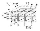
- the sound absorbing structure 901 includes a housing 902 having a surface plate 902a made of a porous plate on one surface, and a plurality of porous plates 90 and 91 parallel to the surface plate 902a are provided inside the housing 902. And a plurality of resin partition walls 92 to 94 extending in a direction orthogonal to the surface plate 902a.
- the partition wall 92 is disposed in a space between the surface plate 902a and the porous plate 90, and partitions this space into a plurality of spaces 95 arranged in the longitudinal direction.
- the partition walls 93 and 94 are disposed between the perforated plate 90 and the perforated plate 91 and between the perforated plate 91 and the back plate 902b, respectively. It is partitioned into a plurality of spaces 96 and 97 arranged in the longitudinal direction.
- the sound absorbing structure 901 absorbs sound around the resonance frequency corresponding to the volume of each air layer 95 to 97 and, for example, resonance corresponding to the volume of the space where the two air layers 95 and 96 are combined. Sound around the frequency and sound around the resonance frequency corresponding to the volume of the space where the three air layers 95 to 97 are combined can be absorbed. Therefore, the lowest frequency of the sound absorption band of the sound absorbing structure 901 is a resonance frequency corresponding to the volume of the space where all the three air layers 95 to 97 are combined.
- the space where all the three air layers 95 to 97 are combined is a space partitioned by the partition walls 92 to 94 with respect to the surface direction of the surface plate 902a, and its volume is relatively small. Therefore, the resonance frequency corresponding to the volume of this space is a relatively high frequency. Therefore, the conventional sound absorbing structure 901 as shown in FIGS. 18A and 18B can obtain high sound absorbing performance only within a relatively narrow frequency band in the high frequency range.
- an object of the present invention is to provide a sound absorbing structure that can broaden the sound absorption band and has high sound absorption efficiency.
- the sound absorbing structure is provided with a housing having a surface plate made of a perforated plate on one surface, and disposed inside the housing so as to face the surface plate, and an internal space of the housing.
- a first perforated plate that is divided into a plurality of spaces arranged in a direction orthogonal to the surface plate, and disposed in the interior of the housing along a direction intersecting the surface plate.
- a second perforated plate partitioned into a plurality of spaces arranged in the surface direction.
- the sound absorbing structure includes a housing having a surface plate made of a porous plate on one surface, and a plurality of porous plates arranged in the surface of the surface plate inside the housing.
- a plurality of perforated plate units each formed of a perforated plate, wherein the perforated plate unit is disposed to face the surface plate, and the internal space of the housing is defined as the surface plate.
- the sound absorbing structure according to the second aspect is characterized in that the side surface portions of the two adjacent perforated plate units are arranged with a gap therebetween.
- the sound absorbing structure according to the second or third aspect is configured such that, of the plurality of perforated plate units, the side surface portion of the perforated plate unit adjacent to the inner surface of the casing is It is characterized by being arranged with a gap between the inner surface of the housing.
- the sound absorbing structure according to the third or fourth aspect is characterized in that the side surface portion has a protruding portion that protrudes on the opposite side to the flat surface portion.
- the sound absorbing structure is integrally formed by bending the single perforated plate in the flat surface portion and the side surface portion in any one of the second to fifth aspects. It is characterized by being.
- the sound absorbing structure is characterized in that, in any of the second to fifth aspects, the edge of the flat part is fixed to the side part.
- the side surface portion is formed of a perforated plate, and a sandwiching portion that presses and sandwiches the edge of the flat portion from both sides. It is characterized by having.
- the sound absorbing structure according to any one of the second to eighth aspects is arranged such that the side surface portion surrounds the planar portion when viewed from a direction orthogonal to the surface plate.
- the flat surface portion is connected to the side surface portion around the entire circumference.
- the sound absorbing structure according to the ninth aspect has a box shape in which the perforated plate unit includes a bottom wall serving as the flat surface portion and four side walls serving as the side surface portions.
- the plurality of box-like bodies have different lengths in the direction orthogonal to the surface plate, and the sizes of the openings surrounded by the four side walls are substantially the same, It is characterized in that the opening side is nested so as to be in contact with the surface of the housing facing the surface plate.
- the sound-absorbing structure is a space that combines the sound around the resonance frequency corresponding to each space partitioned by the first perforated plate and the second perforated plate, and a plurality of spaces arranged in a direction orthogonal to the surface plate.
- the sound absorbing structure can widen the sound absorption band to the low frequency region side as compared to the case where a plate material without holes is used instead of the second perforated plate.
- the sound absorbing structure not only absorbs sound using the holes formed in the surface plate and the first perforated plate, but also absorbs sound using the holes formed in the second perforated plate. Will improve.
- a plurality of spaces partitioned by the plane portions and the side portions of the plurality of perforated plate units are formed in the internal space of the casing.
- the plurality of spaces communicate with each other through holes formed in the flat surface portion and the side surface portion. Therefore, the sound-absorbing structure has a resonance frequency corresponding to the sound around the resonance frequency corresponding to each space partitioned by the plane portion and the side surface portion, or the space combining a plurality of spaces arranged in a direction orthogonal to the surface plate.
- the sound absorption structure can expand the sound absorption band to the low frequency region side as compared with the case where a plate member without a hole is used as the side surface portion. Moreover, since the sound absorbing structure not only absorbs sound using the holes formed in the surface plate and the flat portion, but also absorbs sound using the holes formed in the side surface portion, the sound absorbing efficiency is improved. Furthermore, a method of installing a plurality of perforated plate units formed of perforated plates inside the housing includes a porous plate in a direction facing the surface plate on the inner surface of the housing, and a porous plate in a direction intersecting the surface plate. Therefore, the sound absorbing structure can be easily manufactured. Also, by changing the number of perforated plate units or changing some of the perforated plate units to perforated plate units made of perforated plates with different hole diameters, etc. Can be easily adjusted according to the purpose of use.
- the side surfaces of two adjacent perforated plate units are arranged in close contact with each other, the hole on one side surface is easily blocked by the other side surface and In order to prevent this, it is necessary to make the positions of the holes on both side surfaces coincide with each other, which makes manufacturing difficult.
- the side surfaces of two adjacent perforated plate units are arranged with a gap between each other. Therefore, even if the positions of the holes on both side surface portions do not coincide with each other, a plurality of side surfaces are aligned in the surface direction. The space can be communicated through a hole in the side surface.
- the sound absorbing structure can absorb sound around the resonance frequency corresponding to each space surrounded by the side surface portion and the flat portion, and the space surrounded by the side surface portion and the flat surface portion and the gap.
- the sound around the resonance frequency corresponding to the space combined with the space formed by can be absorbed. Therefore, the sound absorbing structure can broaden the sound absorption band compared to the case where no gap is formed between the side surface portion of the perforated plate unit and the inner surface of the casing.
- the side surface portions of the two adjacent porous plate units or the inner surface and the side surface portion of the casing are not in close contact with each other. A gap is always formed.
- the flat surface portion is less likely to vibrate in a direction orthogonal to the surface direction, so that it is possible to suppress a decrease in sound absorption performance due to vibration.
- the flat surface portion is less likely to vibrate in a direction orthogonal to the surface direction, so that it is possible to suppress a decrease in sound absorption performance due to vibration.
- the edge portion of the flat surface portion can be fixed to the side surface portion without particularly using a member other than the porous plate, the manufacturing cost of the porous plate unit can be reduced.
- the strength of the perforated plate unit is increased.
- the perforated plate unit can be easily manufactured. Further, by changing the number of box-shaped bodies constituting the perforated plate unit and the length of the box-shaped body in the depth direction, the sound absorption characteristics of the sound absorbing structure can be easily adjusted according to the purpose of use. .
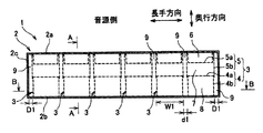
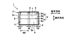
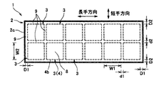
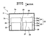
- FIG. 1A It is a longitudinal direction sectional view of a sound absorption structure concerning a 1st embodiment of the present invention. It is the sectional view on the AA line of FIG. 1A. It is BB sectional drawing of FIG. 1A. It is sectional drawing of the sound absorption structure of other embodiment of this invention. It is sectional drawing of the sound absorption structure which concerns on 2nd Embodiment of this invention, and is a figure equivalent to FIG. 1B. It is sectional drawing of the sound absorption structure which concerns on 3rd Embodiment of this invention. It is the elements on larger scale of FIG. 4A. It is sectional drawing of the sound absorption structure of other embodiment of this invention. It is an example of the CC sectional view taken on the line of FIG. 5A.
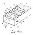
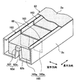
- the sound absorbing structure 1 includes a rectangular parallelepiped casing 2 and a plurality of perforated plate units 3 disposed inside the casing 2.
- the housing 2 includes a rectangular surface plate 2a in which a large number of through holes are formed on one surface.
- the sound absorbing structure 1 is arranged such that the surface plate 2a side is the sound source side.
- the longitudinal direction and the short direction of the surface plate 2a are simply defined as the longitudinal direction and the short direction, and the direction orthogonal to the surface plate 2a is defined as the depth direction.
- the housing 2 includes a surface plate 2a made of a perforated plate, a back plate 2b disposed to face the surface plate 2a, and a frame portion formed integrally with the back plate 2b. 2c.
- the size of the casing 2 is, for example, a length in the longitudinal direction of 2000 mm, a length in the lateral direction of 500 mm, and a length in the depth direction of 95 mm.
- the housing 2 is not limited to the above size.
- the back plate 2b and the frame portion 2c are formed of a metal material such as iron or stainless steel, fiber reinforced resin, or the like.
- the surface plate 2a may be detachably attached to the end portion of the frame portion 2c with screws or the like, or may be fixed to the end portion of the frame portion by rivets or fitting.
- the surface plate 2a for example, an aluminum plate having a thickness of about 1.0 mm and a perforated plate in which a large number of circular through holes are formed is used.
- the diameter of the through hole of the surface plate 2a is, for example, about 0.3 to 3.0 mm, and the aperture ratio of the surface plate 2a is, for example, 10% or less.
- the shape of the through hole is not limited to a circle, and may be a polygonal shape such as a quadrangle or a triangle.
- the through hole may be configured by a slit.
- the diameter of the through hole is a diameter of a circular hole having an equivalent hole area.
- the plate thickness, the aperture ratio, and the diameter of the through hole of the surface plate 2a are set so as to cause viscosity to the air passing through the through hole.
- a viscous action occurs in the air passing through the through-hole, conversion of air vibration into thermal energy is promoted, and sound absorption performance is improved.
- seat etc. are affixed on the area
- a plurality of (12 in this embodiment) perforated plate units 3 are arranged side by side in the surface direction of the surface plate 2 a.
- the perforated plate unit 3 is formed of a perforated plate and has a quadrangular cylindrical outer shape extending in the depth direction. As shown in FIG. 1C, the plurality of perforated plate units 3 are arranged side by side in the longitudinal direction and in the lateral direction.
- the perforated plate unit 3 includes a first member 4 formed in a box-like body opened on the back plate 2b side, and a cross-sectional shape in the short side direction and the long side direction formed in an H shape.
- the second member 5 is formed.
- the first member 4 is installed on the back plate 2b.
- the first member 4 may be fixed to the back plate 2b, but may not be fixed.
- the 1st member 4 is comprised from the plane part 4a arrange
- the side surface portion 4b is disposed so as to surround the flat surface portion 4a when viewed from the depth direction, and the flat surface portion 4a is coupled to the end portion of the side surface portion 4b on the surface plate 2a side in the entire periphery.
- the second member 5 is attached to the end of the first member 4 on the surface plate 2a side.
- the 2nd member 5 is comprised from the plane part 5a arrange
- the side surface portion 5b is disposed so as to surround the flat surface portion 5a when viewed from the depth direction, and the flat surface portion 5a is connected to the substantially central portion of the side surface portion 5b in the depth direction on the entire circumference thereof.
- the second member 5 is fixed by fitting the opening end portion on the back plate 2b side outside the end portion on the surface plate 2a side of the first member 4. In addition to this fitting and fixing, it may be further fixed using a stapler, an adhesive, an adhesive tape or the like.
- the flat portions 4a and 5a are each parallel to the surface plate 2a.
- the side surface portions 4b and 5b are each composed of two surfaces orthogonal to the longitudinal direction and two surfaces orthogonal to the lateral direction.
- the side surface portion 4b of the first member 4 and the side surface portion 5b of the second member 5 constitute a side surface portion of the porous plate unit of the present invention.
- the length in the depth direction of the perforated plate unit 3 is substantially the same as the length in the depth direction of the internal space of the housing 2.
- the lengths of the first member 4 and the second member 5 in the longitudinal direction are substantially the same, and the lengths in the short direction are also substantially the same.
- the length in the longitudinal direction of the first member 4 and the second member 5 is W1, and the length in the short direction is W2.
- the side surface portions 4b (5b) of two perforated plate units 3 adjacent to each other in the longitudinal direction are arranged with a gap d1 therebetween.
- the side surface portion 4b (5b) of the perforated plate unit 3 adjacent to the frame portion 2c with respect to the longitudinal direction is disposed with a gap D1 between the side surface portion 4b and the frame portion 2c.
- the side surface parts 4b (5b) of the two perforated plate units 3 adjacent to each other in the short direction are arranged with a gap d2 therebetween.
- the side surface portion 4b (5b) of the perforated plate unit 3 adjacent to the frame portion 2c in the short direction is disposed with a gap D2 between the side surface portion 4b and the frame portion 2c. Furthermore, as shown in FIG.
- the spaces formed by the plurality of gaps D 1, D 2, d 1, and d 2 are in communication with each other to form a space 9.
- one space surrounded by the side surface parts 4 b and 5 b, the surface plate 2 a and the back plate 2 b is formed. That is, the side surface portion of one perforated plate unit 3 partitions the internal space of the housing 2 into a plurality of spaces arranged in the surface direction of the surface plate 2a.
- the space surrounded by the side surfaces 4b and 5b, the surface plate 2a, and the back plate 2b is divided into three air chambers 6 to 8 arranged in the depth direction by the two flat surfaces 4a and 5a.
- the air chamber 6 is a space surrounded by the surface plate 2a, the flat surface portion 5a, and the side surface portion 5b.
- the air chamber 7 is a space surrounded by the flat surface portion 5a, the flat surface portion 4a, and the side surface portion 5b.
- the air chamber 8 is a space surrounded by the flat surface portion 4a, the back plate 2b, and the side surface portion 4b.
- the longitudinal width (length in the longitudinal direction of the first member 4 and the second member 5) W1 of the air chambers 6 to 8 is set to be smaller than 1 ⁇ 2 of the wavelength of the sound to be absorbed. It is preferred that The width in the short direction of the air chambers 6 to 8 (the length in the longitudinal direction of the first member 4 and the second member 5) W2, as well as the length in the longitudinal direction, is 1 ⁇ 2 of the wavelength of the sound to be absorbed. Is preferably set to be small. The reason will be described later.
- the lengths of the air chambers 6 to 8 in the depth direction may be different from each other, but may be the same.
- the first member 4 and the second member 5 are each formed by bending one perforated plate. Therefore, the flat surface portion 4a and the side surface portion 4b are integrally formed. Moreover, the plane part 5a and the side part 5b are also integrally formed. Further, of the side surface portion 5b of the second member 5, the portion on the surface plate 2a side with respect to the flat surface portion 5a has a double structure by folding.
- the perforated plate constituting the first member 4 and the second member 5 is, for example, an aluminum thin plate (foil) having a thickness of about 0.1 mm, and a large number of circular through holes are formed.
- the diameter of the through hole of the porous plate is, for example, 0.05 mm to 0.15 mm, and the aperture ratio is, for example, 0.1 to 1.0%.
- the through hole may be a hole formed by punching, or may be a hole formed by the following method.
- ridges and valleys are formed alternately and continuously, and the tips of the ridges and valleys are ductile broken to form minute holes.
- the shape of the hole is not a circle but a shape close to a cross.
- the shape of the through hole is not limited to a circle, and may be a polygonal shape such as a quadrangle or a triangle. Alternatively, it may be slit-shaped.
- the diameter of the through hole is a diameter of a circular hole having an equivalent hole area.
- the aperture ratio, the plate thickness, and the diameter of the through hole of the porous plate are set so as to cause viscosity to the air passing through the through hole for the same reason as the porous plate constituting the surface plate 2a.
- the perforated plates constituting the first member 4 and the second member 5 those having different aperture ratios, hole diameters, and plate thicknesses may be used.
- the sound from the sound source first enters the air chamber 6 through the through hole of the surface plate 2a.
- a specific frequency resonance frequency
- the vibration of the air causes friction between the inner wall of the through hole and the air, and a part of the vibration energy is converted into heat energy, resulting in a sound absorbing action.
- Part of the sound that has entered the air chamber 6 enters the air chamber 7 through the through hole of the flat portion 5a, and further enters the air chamber 8 through the through hole of the flat portion 4a. Similar to the case where the sound passes through the through hole of the surface plate 2a, the sound around the specific frequency corresponding to the opening ratio of the flat portions 4a, 5a passes through the through hole of the flat portions 4a, 5a. Part of the sound is absorbed.
- the sound absorbing structure 1 not only absorbs sound using the through holes of the surface plate 2a and the flat portions 4a and 5a, but also absorbs sound using the through holes of the side surfaces 4b and 5b. Will improve.
- the frequency of sound that can be absorbed by the sound absorbing structure 1 will be described.
- the sound absorbing structure 1 absorbs sound using the through-holes of the surface plate 2a, the plurality of flat surface portions 4a, 5a, and the plurality of side surface portions 4b, 5b.
- the frequency of sound that can be absorbed will be described as an example.
- the sound absorbing structure 1 can absorb sound around the resonance frequency corresponding to the volume of the air chamber 6, and the air chamber Sound around the resonance frequency corresponding to the volume of the space combining the air chamber 6 and the air chamber 7 and sound around the resonance frequency corresponding to the space combining all the air chambers 6 to 8 can be absorbed. Further, since the plurality of air chambers 6 and the spaces 9 arranged in the longitudinal direction and the short side direction communicate with each other through the through holes of the side surface portion 5b, for example, the space of the air chamber 6 and the space 9 combined.
- the two air chambers 7 arranged on the lower side in FIG. 1A in the depth direction of the two air chambers 6 are also combined. Sound around the resonance frequency corresponding to the volume can also be absorbed.
- the plane portions 4a and 5a and the side surface portions 4b and 5b can also absorb sounds around a plurality of resonance frequencies corresponding to the spaces communicating with the respective through holes, similarly to the surface plate 2a.
- the sound absorbing structure 1 has a resonance frequency corresponding to the sound around the resonance frequency corresponding to the volume of each air chamber 6 to 8 and the volume of the space including the air chambers 6 to 8 arranged in the depth direction.
- the sound around the resonance frequency corresponding to the volume of the space including the plurality of air chambers 6 (or air chambers 7 and 8) and the space 9 arranged in the surface direction of the surface plate 2a is also included.
- the sound absorbing structure 1 can expand the sound absorption band to the low frequency region side as compared with the case where the side surface portions 4b and 5b are formed of a plate material in which no through hole is formed.
- the through hole of one side surface portion 4b (5b) is the other side surface portion 4b (5b). Therefore, it is difficult to manufacture the sound absorbing structure 1 because the positions of the through holes of the side surface portions 4b (5b) must be matched.
- the side surface parts 4b (5b) of the two perforated plate units 3 adjacent to each other in the longitudinal direction or the short direction are arranged with a gap d1 or a gap d2. Therefore, even if the positions of the through holes in the side surface portions 4b (5b) are not matched, the plurality of air chambers 6 to 8 adjacent in the longitudinal direction or the short side direction are communicated with each other through the through holes in the side surface portions 4b and 5b. Can be made.
- the sound absorbing structure 1 is provided in each air chamber 6. Can absorb sound around the resonance frequency corresponding to -8, and can also absorb sound around the resonance frequency corresponding to the space formed by the air chambers 6-8 and the space formed by the gap D1 or the gap D2. . Therefore, the sound absorbing structure 1 can broaden the sound absorption band as compared with the case where no gap is formed between the side surface portion 4b of the perforated plate unit 3 and the frame portion 2c.
- the space 9 is formed by connecting spaces formed by a plurality of gaps D1, D2, d1, and d2, the volume of the space 9 is relatively large. Further, the space 9 communicates with all the air chambers 6 to 8 of the plurality of perforated plate units 3. Therefore, the sound absorbing structure 1 can exhibit high sound absorbing performance in a low frequency range.
- the sound absorbing structure 1 such as an expressway
- various loudness (sound pressure) sounds enter the air chamber 6 through the surface plate 2a. Therefore, the volume of sound (sound pressure) in the air chamber 6 of two adjacent perforated plate units 3 may be different.
- the sound of the air chambers 6 to 8 having the higher sound pressure can easily enter the space 9.
- the through-hole in the area of the surface plate 2a that is in contact with the space 9 is blocked, the sound from the outside does not directly enter the space 9, so that the sound can easily enter the space 9 from the air chambers 6-8.
- the sound absorption coefficient at the resonance frequency corresponding to the combined space of the air chambers 6 to 8 and the space 9 and the surrounding frequencies is improved.
- part of the sound that has entered from the through holes of the surface plate 2a or the flat portions 4a and 5a travels in the air chambers 6 to 8 along the longitudinal direction or the short direction.
- the width W1 of the air chambers 6 to 8 is larger than 1 ⁇ 2 of the wavelength of the sound to be absorbed, a resonance phenomenon of sound traveling in the longitudinal direction occurs in the air chambers 6 to 8, and the air chamber There is a case where sound becomes difficult to enter from 6 through 8 through the through hole, and the sound absorption performance is lowered.
- the width W2 of the air chambers 6 to 8 is larger than 1 ⁇ 2 of the wavelength of the sound to be absorbed, the sound absorbing performance may be lowered.
- the widths W1 and W2 of the air chambers 6 to 8 are smaller than 1 ⁇ 2 of the wavelength of the sound to be absorbed, resonance in the air chambers 6 to 8 is prevented. Sound easily enters the air chambers 6 to 8 from the through holes of the surface plate 2a or the flat portions 4a and 5a, and the sound absorption performance is improved.
- the method of installing a plurality of perforated plate units 3 formed of perforated plates inside the housing 2 is that the inner surface of the housing 2 has a plurality of perforated plates in a direction facing the surface plate 2a and a surface plate orthogonal to the surface plates. Since it is easier compared with the case where a plurality of perforated plates in the direction to be installed directly, the sound absorbing structure 1 can be easily manufactured.
- the porous plate unit 3 is formed only of the porous plate, for example, the resin-made partition walls 92 to 94 are not used like the conventional sound absorbing structure 901 shown in FIGS. 18A and 18B.
- the material cost can be reduced and the weight can be reduced.
- each of the first member 4 and the second member 5 is formed by bending a single perforated plate, and the flat surface portions 4a and 5a and the side surface portions 4b and 5b are integrated with each other. It has become. Therefore, the plane portions 4a and 5a are unlikely to vibrate in a direction (depth direction) orthogonal to the surface direction.
- the flat portions 4a and 5a vibrate, the friction between the inner wall of the through hole and the air is reduced, and the sound absorbing performance is lowered.
- the vibrations of the flat portions 4a and 5a are suppressed, it is possible to suppress a decrease in sound absorption performance due to the vibrations.
- the side surfaces 4b and 5b are arranged so as to surround the flat surfaces 4a and 5a when viewed from the depth direction, and the flat surfaces 4a and 5a are connected to the side surfaces 4b and 5b on the entire circumference thereof.
- the perforated plate unit 3 has a relatively high strength.
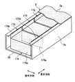
- the sound absorbing structure 1 may be arranged in a state in which the perforated plate unit 3 is rotated by 180 ° about the axis in the direction orthogonal to the surface plate 2a. That is, the structure may be such that the second member 5 is installed on the back plate 2b, and the second member 4 that is open on the surface plate 2a side is attached to the surface plate 2a side of the second member 5.
- the sound absorbing structure may include a plurality of perforated plate units 3 ′ formed by connecting two second members 5 in the depth direction.
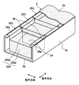
- the sound absorbing structure 21 of the second embodiment is different in the shape of the perforated plate unit, but the other configurations are the same as those of the first embodiment.
- the perforated plate unit 23 includes a large box 24 opened on the back plate 2 b side, and a small box 25 arranged inside the large box 24 and opened on the back plate 2 b side. It is configured.
- the large box 24 and the small box 25 are each fixed to the back plate 2b.
- the large box 24 is composed of a bottom wall (planar portion) 24a disposed to face the surface plate 2a, and a side wall portion (side surface portion) 24b extending in the depth direction.
- the small box 25 includes a bottom wall (planar portion) 25a disposed to face the surface plate 2a and a side wall portion (side surface portion) 25b extending in the depth direction.
- the bottom walls 24a and 25a are each parallel to the surface plate 2a.
- the side wall parts 24b and 25b are each comprised from the two side walls orthogonal to a longitudinal direction, and the two side walls orthogonal to a transversal direction.
- the side walls 24b and 25b are arranged so as to surround the bottom walls 24a and 25a, respectively, when viewed from the depth direction.
- the bottom walls 24a and 25a are connected to the end portions on the surface plate 2a side of the side wall portions 24b and 25b, respectively, on the entire circumference.
- the side wall portion 24b of the large box 24 and the side wall portion 25b of the child box constitute a side surface portion of the porous plate unit of the present invention.
- the length in the depth direction of the large box 24 is shorter than the length in the depth direction of the internal space of the housing 2.
- the length of the small box 25 in the depth direction is shorter than the length of the large box 24 in the depth direction. That is, the lengths of the large box 24 and the small box 25 in the depth direction are different from each other.
- the length in the longitudinal direction and the length in the lateral direction of the small box 25 are substantially the same, but the large box 24 is slightly larger.
- the large box 24 and the small box 25 are stacked in a nested manner with the opening sides fixed to the back plate 2b.
- the side wall portions 24b of two perforated plate units 23 adjacent to each other in the longitudinal direction are arranged with a gap therebetween.
- the side wall part 24b of the perforated plate unit 23 adjacent to the frame part 2c in the longitudinal direction is disposed with a gap between the side wall part 24c and the frame part 2c.
- the side wall portions 24b of the two perforated plate units 23 adjacent to each other in the short direction are arranged with a gap between them, and the side wall portion 24b of the perforated plate unit 23 adjacent to the frame portion 2c in the short side direction is And a space between the frame portion 2c (see FIG. 3).
- the space formed by these gaps is in communication and forms a space 29.
- a single air chamber 26 surrounded by the bottom wall 24a of the plurality of perforated plate units 23, the surface plate 2a, and the frame portion 2c is formed in the internal space of the casing 2. That is, the bottom wall 24a partitions the internal space of the housing 2 into two spaces arranged in the depth direction.
- the air chamber 26 communicates with the space 29 described above.
- a space surrounded by the side wall portion 24 b (and the side wall portion 25 b), the bottom wall 24 a and the back plate 2 b of the perforated plate unit 23 is formed. That is, the side wall part 24b (and side wall part 25b) of one perforated plate unit 23 partitions the internal space of the housing 2 into a plurality of spaces arranged in the surface direction of the surface plate 2a.
- the space surrounded by the side wall 24b, the bottom wall 24a, and the back plate 2b is partitioned into two air chambers 27 and 28 arranged in the depth direction by the bottom wall 25a.
- the large box 24 and the small box 25 are each formed by bending one perforated plate. Therefore, the bottom wall 24a and the side wall part 24b, and the bottom wall 25a and the side wall part 25b are integrally formed, respectively. Accordingly, the bottom walls 24a and 25a are less likely to vibrate in a direction (depth direction) orthogonal to the surface direction, and thus it is possible to suppress a decrease in sound absorption performance due to vibration.
- the same perforated plates as in the first embodiment can be used.
- the perforated plates constituting the large box 24 and the small box 25 those having different aperture ratios, hole diameters, and plate thicknesses may be used.
- the sound absorbing structure 21 having the above-described configuration corresponds to the sound around the resonance frequency corresponding to the volume of each air chamber 26 to 28 and the volume of the space including the air chambers 26 to 28 arranged in the depth direction.
- the sound around the resonance frequency corresponding to the volume of the space of the plurality of air chambers 27 (or air chambers 28) arranged in the surface direction of the surface plate 2a is also absorbed. it can. Therefore, the sound absorbing structure 21 can expand the sound absorption band to the low frequency region side as compared with the case where the side wall portions 24b and 25b are formed of a plate material in which no through hole is formed.
- the sound absorption is performed using the through holes of the surface plate 2a and the bottom walls 24a and 25a, but the sound absorption efficiency is improved because the sound absorption is also performed using the through holes of the side wall portions 24b and 25b.
- the length in the longitudinal direction and the length in the short direction of the air chamber 26 are the same as the length in the longitudinal direction and the length in the short direction of the internal space of the housing 2. Therefore, the longitudinal widths of the air chamber 26 and the air chamber 27 are different from each other, and the positions of both end portions in the longitudinal direction of the air chambers 26 and 27 are different from each other. Therefore, sound interference (sound pressure interference) occurs between the air chambers 26 and 27, and resonance of sound traveling in the longitudinal direction is less likely to occur in the air chambers 26 and 27. Thereby, it becomes easy for sound to enter the air chambers 26 and 27, and the sound absorption performance is improved.
- the air chambers 26 and 27 In the short direction, similar to the longitudinal direction, the air chambers 26 and 27 have different widths and positions at both ends, so that the same effect can be obtained.
- the large box 24 and the small box 25 are formed by bending, and the perforated plate unit 23 has a simple structure in which the large box 24 and the small box 25 are stacked in a nested manner, and thus is easily manufactured. be able to.
- the sound absorption characteristics of the sound absorbing structure 21 can be changed according to the purpose of use. It can be adjusted easily.
- the perforated plate unit 23 of the present embodiment has a structure in which two box-like bodies 24 and 25 are nested, but three or more box-like bodies having different lengths in the depth direction are nested.
- a stacked configuration may be used.
- a configuration in which two or more box-shaped bodies are arranged side by side in the surface direction of the surface plate 2a inside the large box 24 may be employed.
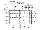
- the sound absorbing structure 31 of the third embodiment is the same as the first embodiment except for the shape of the perforated plate unit.
- the porous plate unit 33 of the third embodiment is composed of two flat surface portions 33a arranged to face the surface plate 2a, and a side surface portion 33b extending in the depth direction. .
- the two flat portions 33a are parallel to the surface plate 2a, and are arranged side by side in the depth direction.
- the side surface portion 33b is disposed so as to surround the flat surface portion 33a when viewed from the depth direction, and the flat surface portion 33a is fixed to the side surface portion 33b on the entire circumference thereof.
- the side part 33b is comprised from two surfaces orthogonal to a longitudinal direction, and two surfaces orthogonal to a transversal direction.
- the length in the extending direction (depth direction) of the side surface portion 33 b is substantially the same as the length in the depth direction of the internal space of the housing 2.
- the two flat portions 33a are each composed of a single perforated plate.
- the side surface portion 33b is formed by one or a plurality of perforated plates.
- the porous plate which comprises the plane part 33a and the side part 33b can use the porous plate similar to 1st Embodiment.
- the perforated plate constituting the flat surface portion 33a and the side surface portion 33b those having different aperture ratios, hole diameters, and plate thicknesses may be used.
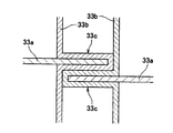
- the side surface portion 33b is provided with two clamping portions 33c for clamping the two flat surface portions 33a.
- the clamping part 33c is formed by a part of the perforated plate constituting the side part 33b.
- the clamping part 33c clamps the flat part 33a over the entire circumference.
- the clamping portion 33c is formed to protrude outward (on the side opposite to the flat surface portion 33a), and holds the edge portion of the flat surface portion 33a by pressing from both sides.
- the clamping part 33c is formed, for example, by bending a part of the porous plate constituting the side part 33b so as to be in close contact with both sides of the edge part of the flat part 33a when the side part 33b is formed.
- the front end portion of the sandwiching portion 33 c is in contact with the side surface portion 33 b of the adjacent perforated plate unit 33.
- the sandwiching portions 33c of the two adjacent porous plate units 33 are formed such that their heights (depth direction positions) are different from each other.
- the upper surface (or the lower surface) of the sandwiching portion 33c is formed at a height in contact with the lower surface (or the upper surface) of the adjacent sandwiching portion 33c. The same applies to the holding portion 33c. This is because the strength of the sandwiching portion 33c can be improved.
- the edge of the flat surface portion 33a can be fixed to the side surface portion 33b without using a member other than the porous plate, so that the manufacturing cost of the porous plate unit 33 can be reduced. Can be reduced. Moreover, since the side part 33b is formed with the aluminum thin plate of about 0.1 mm, the clamping part 33c can be easily formed by the method mentioned above.
- the sandwiching portion 33c is formed so as to protrude outward, the side surface portions 33b of the two perforated plate units 33 adjacent to each other in the longitudinal direction or the short-side direction are arranged with a gap therebetween. Further, the side surface portion 33b of the perforated plate unit 33 adjacent to the frame portion 2c with respect to the longitudinal direction or the short side direction is disposed with a gap between it and the frame portion 2c. The space formed by these gaps communicates with respect to the surface direction, and is partitioned into three spaces 37 to 39 arranged in the depth direction by the two clamping portions 33c.
- the sound absorbing structure 31 having the above-described configuration corresponds to the sound around the resonance frequency corresponding to the volume of each of the air chambers 34 to 36 and the volume of the space including the air chambers 34 to 36 arranged in the depth direction.
- the sound around the resonance frequency corresponding to the volume of the space of the plurality of air chambers 34 (or air chambers 35, 36) arranged in the surface direction of the surface plate 2a can be absorbed.
- Can also absorb sound. Therefore, the sound absorbing structure 31 can expand the sound absorption band toward the low frequency region as compared with the case where the side surface portion 33b is formed of a plate material in which no through hole is formed.
- the sound absorption is performed using the through holes of the surface plate 2a and the flat surface portion 33a, but the sound absorption efficiency is improved because the sound absorption is also performed using the through holes of the side surface portion 33b.
- the edge of the flat portion 33a is fixed to the clamping portion 33c. Therefore, the flat surface portion 33a is less likely to vibrate in a direction (depth direction) orthogonal to the surface direction, so that it is possible to suppress a decrease in sound absorption performance due to vibration.
- the holding portion 33c holds the flat portion 33a over the entire circumference, but is not limited to this configuration.
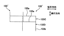
- the sandwiching portion 133c may be formed on the side surface portion 133b so as to sandwich both end portions in the longitudinal direction (or short direction) of the flat surface portion 133a.
- the two side surfaces where the clamping portion is not formed and the flat surface portion 133a may be integrally formed by bending.
- the perforated plate unit 133 may have a cross-sectional shape in the short-side direction in which two H-shaped members 133 ⁇ / b> A and 133 ⁇ / b> B are connected in the depth direction.
- Each of the H-shaped members 133A and 133B is formed by bending one perforated plate so that the cross section in the lateral direction is an H shape. Further, for example, as shown in FIG.
- the cross-sectional shape in the short direction may be a perforated plate unit 133 ′ in which two Z-shaped members 133 ⁇ / b> C and 133 ⁇ / b> D are connected in the depth direction.
- the Z-shaped members 133C and 133D are formed by bending both ends of one perforated plate in opposite directions. However, in this case, almost no gap is formed between the perforated plate units adjacent in the lateral direction.
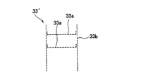
- the porous plate unit 33 of the present embodiment uses the sandwiching portion 33c formed of a porous plate as means for fixing the flat portion 33a to the side surface portion 33b, but is not limited to this configuration.
- a perforated plate unit 33 ′ in which the edge portion of the flat portion 33 a is bent and the bent portion is fixed to the side surface portion 33 b using an adhesive or the like may be used.
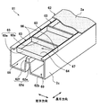
- the sound absorbing structure 41 of the fourth embodiment includes a housing 2 similar to that of the first embodiment, and a plurality of perforated plate units 43 arranged in the longitudinal direction inside the housing 2. Composed.
- the perforated plate unit 43 has a U-shaped U-shaped member 44 that is open on the back plate 2b side and a U-shaped member 44 that is substantially similar in shape to the U-shaped member 44. In this case, the U-shaped member 45 is shorter than the U-shaped member 44 in the depth direction.
- the two U-shaped members 44 and 45 are each fixed to the back plate 2b.
- the U-shaped members 44 and 45 are respectively composed of flat portions 44a and 45a arranged to face the surface plate 2a, and side portions 44b and 45b extending in the depth direction.
- the side parts 44b and 45b are each comprised from two surfaces orthogonal to a longitudinal direction. Two opposing edge portions of the flat surface portions 44a and 45a are connected to the end portions of the side surface portions 44b and 45b on the surface plate 2a side. Side portions 44b and 45b of the two U-shaped members 44 and 45 constitute side portions of the perforated plate unit of the present invention.
- the length of the U-shaped member 44 in the depth direction is shorter than the length of the internal space of the housing 2 in the depth direction. Further, the length of the U-shaped member 45 in the depth direction is shorter than the length of the U-shaped member 44 in the depth direction.
- the lengths in the longitudinal direction and the length in the short direction of the U-shaped members 44 and 45 are substantially the same, but the U-shaped member 44 is slightly larger.
- the U-shaped member 44 and the U-shaped member 45 are nested in a state where the opening side is fixed to the back plate 2b.
- the side surface portions 44b of the two perforated plate units 43 adjacent to each other in the longitudinal direction are arranged with a gap therebetween.
- a space formed by the gap is referred to as a space 49.
- the side surface portion 44b of the perforated plate unit 43 adjacent to the frame portion 2c with respect to the longitudinal direction is disposed with a gap between it and the frame portion 2c.
- a space formed by the gap is referred to as a space 49a.
- An air chamber 46 is formed by the flat portion 44a, the surface plate 2a, and the frame portion 2c (see FIGS. 1A to 1C) of the plurality of U-shaped members 44.
- the air chamber 46 communicates with the above-described spaces 49 and 49a.
- one space surrounded by the side surface portion 44b, the flat surface portion 44a, and the back plate 2b of the perforated plate unit 43 is formed, and this space is further defined by the flat surface portion 45a. It is partitioned into two air chambers 47 and 48 arranged in the depth direction.
- the two U-shaped members 44 and 45 are each formed by bending one perforated plate. Therefore, the flat part 44a and the side part 44b, and the flat part 45a and the side part 45b are integrally formed, respectively. As a result, the flat portions 44a and 45a are less likely to vibrate in a direction (depth direction) perpendicular to the surface direction, and hence a decrease in sound absorption performance due to vibration can be suppressed.
- porous plate constituting the side surface portions 44b and 45b and the flat surface portions 44a and 45a the same porous plate as in the first embodiment can be used.
- perforated plates constituting the side portions 44b and 45b and the plane portions 44a and 45a those having different aperture ratios, hole diameters, and plate thicknesses may be used.
- the sound absorbing structure 41 having the above-described configuration corresponds to the sound around the resonance frequency corresponding to the volume of each air chamber 46 to 48 and the volume of the space including the air chambers 46 to 48 arranged in the depth direction.
- the sound absorbing structure 51 of the fifth embodiment includes a housing 2 similar to that of the first embodiment, and a plurality of perforated plate units 53 arranged in the longitudinal direction inside the housing 2. Composed.
- the perforated plate unit 53 is formed by bending one perforated plate.
- the perforated plate unit 53 includes a flat part 54, a pair of attachment parts 56, and a side part 55.
- the flat surface portion 54 is disposed to face the surface plate 2a.
- the flat surface portion 54 has a rectangular shape, and its edge portion extends in the longitudinal direction and the lateral direction, respectively.
- the plane part 54 partitions the internal space of the housing 2 into two spaces arranged in the depth direction.
- the pair of attachment portions 56 are connected to opposite edges of the plane portion 54 in the short direction.
- the pair of attachment portions 56 extends in the depth direction from the flat surface portion 54 toward the surface plate 2a side, and is further formed in a shape whose front end is bent outward.
- a portion bent outward is defined as a hook portion 56a.
- the hook portion 56a is hooked on the edge of the frame portion 2c, and the surface plate 2a is installed thereon.
- the hook 56a is sandwiched between the edge of the frame 2c and the surface plate 2a, and the surface plate 2a is fixed to the edge of the frame 2c by rivets or the like. Accordingly, the perforated plate unit 53 is fixed to the housing 2.
- the side part 55 is comprised from the two side walls 55a connected with the edge which opposes regarding the longitudinal direction of the plane part 54. As shown in FIG.
- the side wall 55a extends in the depth direction from the flat portion 54 toward the surface plate 2a side.
- the front end of the side wall 55a may be in contact with the surface plate 2a, but a slight gap may be formed between the surface plate 2a and the front surface plate 2a.
- the side wall 55a partitions the space between the surface plate 2a and the flat portion 54 into a plurality of spaces arranged in the longitudinal direction. Further, the side wall 55a and the attachment portion 56 may be connected, but may not be connected.
- a gap may be formed between the opposing side walls 55a of two adjacent perforated plate units 53, but almost no gap may be formed.
- the perforated plate unit 53 is formed by bending one perforated plate as described above. Specifically, after forming notches or cuts in the four corners of the rectangular perforated plate, one opposing end of the perforated plate is bent vertically to form a U-shape, and the tip is further outside Bend it. That is, it forms in a hat shape. Thus, a pair of attachment portions 56 are formed. Then, the other opposing end portion of the perforated plate is bent perpendicularly to the side opposite to the attachment portion 56 to form two side walls 55 a and a flat portion 54. Note that the attachment portion 56 may be formed after the side wall 55a is formed.
- the sound absorbing structure 51 having the above-described configuration includes the side wall 55a formed of a perforated plate, the sound around the resonance frequency corresponding to the volume of each air chamber 57, 58 and the air arranged in the depth direction
- the sound around the resonance frequency corresponding to the volume of the space combining the chamber 57 and the air chamber 58 can also be absorbed. Sound can also be absorbed. Therefore, the sound absorbing structure 51 can expand the sound absorption band to the low frequency side as compared with the case where the side wall 55a is formed of a plate material in which no through hole is formed.
- the hook portion 56a is fixed to the edge portion of the frame portion 2c together with the surface plate 2a, the perforated plate unit 53 does not move in the housing 2.
- the sound absorbing structure 51 is configured such that the hook portion 56a of the porous plate unit 53 formed by bending one porous plate is hooked on the edge portion of the frame portion 2c, and the surface plate 2a is covered and fixed thereon. Since it is manufactured by a simple method, the manufacturing cost can be reduced.
- the two side walls 55a of the side surface portion 55 extend from the flat surface portion 54 to the surface plate 2a side, but as shown in FIG.
- the two side walls 155a may be the perforated plate unit 153 extending from the flat portion 54 to the back plate 2b side.
- one of the two side walls 255a of the side surface portion 255 extends from the flat surface portion 54 to the surface plate 2a side, and the other side wall 255a extends from the flat surface portion 54 to the back plate 2b side.
- the perforated plate unit 253 may be used.
- the perforated plate unit 53 of the present embodiment has two side walls 55a, it may have only one side wall 55a. Even in this case, the side wall 55a can partition the space in the housing 2 into a plurality of spaces arranged in the longitudinal direction.
- the perforated plate unit 53 may not have the two side walls 55a. However, in this case, the space in the housing 2 is not partitioned with respect to the longitudinal direction.
- a plurality of perforated plate units 53 having different lengths in the depth direction may be nested to form a new perforated plate unit.
- the internal space of the housing 2 can be partitioned into a plurality of spaces in the depth direction.
- the sound absorbing structure 61 includes a casing 62 having a substantially rectangular parallelepiped shape and a plurality of perforated plate units 63 arranged in the casing 62 in the longitudinal direction. Has been.
- the casing 62 includes a surface plate 2a made of a perforated plate, a back plate 62b disposed to face the surface plate 2a, and a frame portion 2c formed integrally with the back plate 62b.
- the back plate 62b is provided with a protruding portion 62d that protrudes toward the surface plate 2a.
- the protruding part 62d is composed of a protruding part 62e formed on the back plate 62b and a spacer block 62f installed on the protruding part 62e.
- the perforated plate unit 63 is formed by bending one perforated plate.
- the perforated plate unit 63 includes a flat surface portion 64, a pair of contact portions 66, and a side surface portion 65.
- the plane part 64 is disposed to face the surface plate 2a.
- the flat surface portion 64 has a rectangular shape, and its edge portion extends in the longitudinal direction and the lateral direction, respectively.
- the plane part 64 partitions the internal space of the housing 62 into two spaces arranged in the depth direction.
- the plane part 64 is installed on the protrusion part 62d. Therefore, the protrusion 62d partitions the space between the flat portion 64 and the back plate 62b into two spaces arranged in the short direction.
- the flat surface portion 64 may be merely placed on the protruding portion 62d, but may be fixed with a rivet or the like.
- the pair of contact portions 66 are connected to opposite edges of the plane portion 64 in the short direction.
- the pair of contact portions 66 extends in the depth direction from the flat surface portion 64 toward the surface plate 2a side.
- the length in the depth direction of the contact portion 66 is set to be substantially the same as the length from the tip of the protruding portion 62d to the surface plate 2a, and the tip of the contact portion 66 is in contact with the surface plate 2a.
- the perforated plate unit 63 is fixed in the housing 62.
- the side part 65 is comprised from the two side walls 65a connected with the edge part which opposes regarding the longitudinal direction of the plane part 64. As shown in FIG.
- the side wall 65a extends in the depth direction from the flat surface portion 64 toward the surface plate 2a side.
- the front end of the side wall 65a may be in contact with the surface plate 2a, but a slight gap may be formed between the front surface plate 2a.
- the side wall 65a partitions the space between the surface plate 2a and the flat portion 64 into a plurality of spaces arranged in the longitudinal direction.
- the side wall 65a and the contact part 66 may be connected, but do not need to be connected.
- a gap may be formed between the opposing side walls 65a of the two adjacent perforated plate units 63, but almost no gap may be formed.
- a plurality of air chambers 67 surrounded by the surface plate 2 a, the flat surface portion 64 and the side surface portion 65 of the porous plate unit 63, a back plate 62 b, a protruding portion 62 d, and a plurality of porous plate units 63 are provided.
- Two air chambers 68 and 69 surrounded by the flat portion 64 are formed.
- the perforated plate unit 63 is formed by bending one perforated plate as described above. Specifically, it is formed by forming notches or notches at four corners of a rectangular perforated plate, and then bending the peripheral portion of the perforated plate vertically.
- the sound absorbing structure 61 having the above-described configuration has the side wall 65a formed of a perforated plate, the sound around the resonance frequency corresponding to the volume of each air chamber 67 to 69 and the air lined up in the depth direction.
- the resonance frequency corresponding to the volume of the space combining the chamber 67 and the air chamber 68 (69) can be absorbed. Therefore, the sound absorption structure 61 can expand the sound absorption band to the low frequency region side as compared with the case where the side wall 65a is formed of a plate material in which no through hole is formed.
- the tips of the pair of contact portions 66 are in contact with the surface plate 2a. Since it is fixed, the perforated plate unit 63 does not move in the housing 62.
- the sound absorbing structure 61 is manufactured by a simple method in which a perforated plate unit 63 formed by bending one perforated plate is installed on the protruding portion 62d, and the surface plate 2a is fixed to the frame portion 2c. Therefore, manufacturing cost can be reduced.
- the two side walls 65a extend from the flat surface portion 64 to the surface plate 2a side, but as shown in FIG. 12, the two side walls 165a of the side surface portion 165
- the perforated plate unit 163 extending from the flat surface portion 64 toward the back plate 62b may be used.
- one of the two side walls may be a unit in a perforated plate that extends from the flat surface portion 64 to the front surface plate 2a side and the other extends from the flat surface portion 64 to the back surface plate 62b side.
- the perforated plate unit 63 of the present embodiment has two side walls 65a, it may have only one of the side walls 65a. Even in this case, the side wall 65a can partition the space in the housing 2 into a plurality of spaces arranged in the longitudinal direction.
- the perforated plate unit 63 may not have the side surface portion 65. However, in this case, the space in the housing 2 is not partitioned with respect to the longitudinal direction.
- the pair of contact portions 66 may not be provided.
- the perforated plate unit 63 is fixed in the casing 62 by the tips of the two side walls 65a being in contact with the surface plate 2a in a state where the flat portion 64 is placed on the protruding portion 62d.
- the sound absorbing structure 71 of the seventh embodiment includes a housing 2 similar to that of the first embodiment, and a plurality of perforated plate units 73 arranged in the longitudinal direction inside the housing 2. Composed.
- the perforated plate unit 73 is formed by bending one perforated plate.
- the perforated plate unit 73 includes a flat surface portion 74 and a side surface portion 75.
- the plane part 74 is disposed to face the surface plate 2a.
- the flat portion 74 has a rectangular shape, and its edge extends in the longitudinal direction and the short direction.
- the plane part 74 partitions the internal space of the housing 2 into two spaces arranged in the depth direction.
- the side surface portion 75 is composed of two side walls 75a connected to opposite edges in the longitudinal direction of the flat surface portion 74 and two side walls 75b connected to opposite edges in the short direction of the flat surface portion 74. ing.
- the two side walls 75a extend in the depth direction from the plane portion 74 toward the surface plate 2a, and the two side walls 75b extend in the depth direction from the plane portion 74 toward the back plate 2b.
- the total length of the side wall 75a and the side wall 75b in the depth direction (the length in the depth direction of the perforated plate unit 73) is set to be approximately the same as the length in the depth direction in the housing 2.
- the front ends of the side walls 75a and 75b are in contact with the front plate 2a and the back plate 2b, respectively, so that the perforated plate unit 73 is fixed in the housing 2.
- the side wall 75a partitions the space between the surface plate 2a and the flat portion 74 into a plurality of spaces arranged in the longitudinal direction.
- a gap may be formed between the opposing side walls 75a of two adjacent perforated plate units 73, but almost no gap may be formed.
- the perforated plate unit 73 is formed by bending one perforated plate as described above. Specifically, it is formed by forming notches at the four corners of a rectangular perforated plate and then bending the peripheries of the perforated plate vertically so that adjacent edges are opposite to each other.
- the sound absorbing structure 71 having the above configuration has the side wall 75a formed of a perforated plate, the sound around the resonance frequency corresponding to the volume of each air chamber 76, 77 and the air arranged in the depth direction
- the sound around the resonance frequency corresponding to the volume of the space combining the chamber 76 and the air chamber 77 can be absorbed. Sound can also be absorbed. Therefore, the sound absorbing structure 71 can expand the sound absorption band to the low frequency region side as compared with the case where the side wall 75a is formed of a plate material in which no through hole is formed.
- the porous plate unit 73 is fixed in the housing 2 by the tips of the two side walls 75a being in contact with the surface plate 2a and the tips of the two side walls 75b being in contact with the back plate 2b.
- the perforated plate unit 73 does not move within the housing 2.
- the sound absorbing structure 71 is manufactured by a simple method in which a perforated plate unit 73 formed by bending a single perforated plate is installed in the housing 2 and then the surface plate 2a is fixed to the frame portion 2c. Therefore, the manufacturing cost can be reduced.
- the side wall 75a extends to the surface plate 2a side
- the side wall 75b extends to the back plate 2b side.
- the perforated plate unit 173 may be configured such that the two side walls 175a extending to the back plate 2b side and the two side walls 175b facing each other in the short direction extend to the front plate 2a side.
- the side wall 175a partitions the space between the back plate 2b and the flat portion 74 into a plurality of spaces arranged in the longitudinal direction.
- the perforated plate unit 73 of the present embodiment and the above-described perforated plate unit 173 may be alternately arranged in the longitudinal direction in the housing 2. Thereby, the space between the surface plate 2a and the flat portion 74 is partitioned by the side wall 75a of the perforated plate unit 73, and the space between the back plate 2b and the flat portion 74 is defined by the side wall 175a of the perforated plate unit 173. Partitioned.
- the sound absorbing structure 81 of the eighth embodiment includes a housing 2 similar to that of the first embodiment, and two first perforated plates disposed inside the housing 2 so as to face the surface plate 2 a. 82 and 83, and a plurality of second perforated plates 84 to 86 disposed in the casing 2 along a direction orthogonal to the surface plate 2a.
- the first perforated plates 82 and 83 are arranged in parallel to the surface plate 2a.
- the first perforated plates 82 and 83 are each formed in substantially the same size as the surface plate 2a.
- the plurality of second perforated plates 84 to 86 are arranged in a direction orthogonal to the longitudinal direction.
- the internal space of the housing 2 is divided into three spaces arranged in the depth direction by the first perforated plates 82 and 83.
- the plurality of second perforated plates 84 are disposed between the first perforated plate 82 and the surface plate 2a, and the plurality of air chambers 87 arranged in the longitudinal direction in the space between the first perforated plate 82 and the surface plate 2a. Partitioning.
- the plurality of second perforated plates 85 are disposed between the first perforated plate 82 and the first perforated plate 83, and a space between the first perforated plate 82 and the first perforated plate 83 is formed in the longitudinal direction.
- a plurality of air chambers 88 are partitioned.
- the plurality of second perforated plates 86 are disposed between the back plate 2b and the first perforated plate 83, and the plurality of air chambers 89 arranged in the longitudinal direction in the space between the back plate 2b and the first perforated plate 83 are arranged. Partitioning.
- the first perforated plates 82 and 83 and the second perforated plates 84 to 86 can be installed in the housing 2 by, for example, using the edges of the first perforated plates 82 and 83 and the second perforated plates 84 to 86 as follows: Although there is a method of fixing directly to the frame 2c, it is not particularly limited to this method.
- first perforated plates 82 and 83 and the second perforated plates 84 to 86 those similar to the perforated plates constituting the perforated plate unit 3 of the first embodiment are used.
- perforated plates constituting the first perforated plates 82 and 83 and the second perforated plates 84 to 86 those having different aperture ratios, hole diameters, and plate thicknesses may be used.
- the sound absorbing structure 81 having the above-described configuration has a resonance corresponding to the volume of the space around the resonance frequency corresponding to the volume of each air chamber 87 to 89 and the air chambers 87 to 89 arranged in the depth direction. Not only can the sound around the frequency be absorbed, but also the sound around the resonance frequency corresponding to the volume of the space of the plurality of air chambers 87 (or air chambers 88 and 89) arranged in the plane direction of the surface plate 2a. it can. Therefore, the sound absorbing structure 81 can expand the sound absorption band to the low frequency region side as compared with the case where a plate material having no through hole is used instead of the second porous plates 84 to 86.
- the shape of the housing 2 of the sound absorbing structure of the present invention is not limited to a rectangular parallelepiped shape.
- the shape of the front plate 2a and the back plate 2b may be circular or triangular.
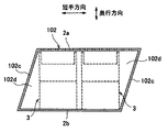
- a housing 102 in which a cross-sectional shape orthogonal to the longitudinal direction is formed in a parallelogram may be used.
- a triangular gap is formed between the frame 102 c of the casing 102 and the side surface of the perforated plate unit 3.
- the volume of the space 102d formed by the triangular gap is larger than the volume of the space formed between the frame portion 2c and the side surface portion of the perforated plate unit in the first to fourth embodiments. Therefore, the increase in the sound absorption band compared with the case where the side surface portion is made of a plate material in which no hole is formed is larger than that of the sound absorption structure of the first to eighth embodiments. That is, in the case of the casing 102 having such a shape, it is particularly effective to connect the space 102d and the air chamber in order to widen the sound absorption band.
- the flat portion of the perforated plate unit or the first perforated plate is arranged in parallel to the surface plate 2a, but is arranged in a slightly inclined direction with respect to the surface plate 2a. May be.
- the side surface portion or the second perforated plate of the perforated plate unit is arranged along the direction orthogonal to the surface plate 2a. It may be a direction other than the orthogonal direction.
- the plurality of perforated plate units have the same shape, but the present invention is not limited to this.
- the plurality of perforated plate units may have different lengths in the longitudinal direction or in the short direction.
- the plurality of perforated plate units are arranged in two in the lateral direction and six in the longitudinal direction, but the number of arrangements is not limited to this. For example, one may be arranged in the short direction and a plurality may be arranged in the longitudinal direction.
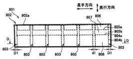
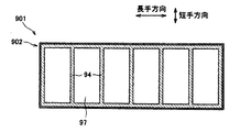
- a sound absorbing structure 801 shown in FIGS. 17A and 17B was produced.
- the sound absorbing structure 801 of the embodiment includes six perforated plate units 803, and these six perforated plate units 803 are arranged inside the housing 802 in the longitudinal direction.
- the surface plate 802a, the flat surface portions 804a and 805a, and the side surface portions 804b and 805b of the sound absorbing structure 801 of the embodiment, the plate thickness, the aperture ratio, and the diameter of the through holes, and the air chambers 806 to 808 and the gaps D1 and d1 The size is shown in Table 1.
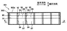
- the sound absorbing structure 901 includes a porous plate 90, 91 parallel to the surface plate 902a of the housing 902 and a plurality of partition walls 92 to 94 extending in a direction orthogonal to the surface plate 902a, inside the housing 902.
- the partition wall 92 is disposed between the surface plate 902a and the porous plate 90, and partitions the space between the surface plate 902a and the porous plate 90 into a plurality of spaces 95 arranged in the longitudinal direction.
- the partition walls 93 and 94 are disposed between the perforated plate 90 and the perforated plate 91 and between the perforated plate 91 and the back plate 902b, respectively, and a plurality of spaces in which the spaces between them are arranged in the longitudinal direction. It is divided into 95-97 respectively.
- Table 1 shows the plate thickness, the aperture ratio, the diameter of the through holes, and the sizes of the air chambers 95 to 97 of the surface plate 902a and the porous plates 90 and 91 of the sound absorbing structure 901 of the comparative example.
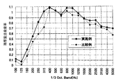
- the reverberation chamber method sound absorption rate was measured. The result is shown in FIG.
- the vertical axis in FIG. 19 indicates the sound absorption rate for the sound from the sound source, and the horizontal axis indicates the 1/3 octave band frequency (Hz).
- the sound absorption rate of the sound absorbing structure 801 of the example is substantially the same as that of the sound absorbing structure 901 of the comparative example in the range of 400 Hz to 630 Hz, but compared with the comparative example in other frequency bands. Has improved. In particular, the sound absorption coefficient in the low frequency range of 250 Hz to 315 Hz is improved. Therefore, it can be seen that the sound absorbing structure 801 of the example has a wider sound absorption band than the sound absorbing structure 901 of the comparative example.
Landscapes
- Physics & Mathematics (AREA)
- Engineering & Computer Science (AREA)
- Acoustics & Sound (AREA)
- Multimedia (AREA)
- Soundproofing, Sound Blocking, And Sound Damping (AREA)
Priority Applications (2)
| Application Number | Priority Date | Filing Date | Title |
|---|---|---|---|
| KR1020107026696A KR101190387B1 (ko) | 2008-05-30 | 2009-05-29 | 흡음 구조체 |
| CN2009801197669A CN102047320A (zh) | 2008-05-30 | 2009-05-29 | 吸音构造体 |
Applications Claiming Priority (4)
| Application Number | Priority Date | Filing Date | Title |
|---|---|---|---|
| JP2008143796 | 2008-05-30 | ||
| JP2008-143796 | 2008-05-30 | ||
| JP2008-286061 | 2008-11-07 | ||
| JP2008286061A JP5171559B2 (ja) | 2008-05-30 | 2008-11-07 | 吸音構造体 |
Publications (1)
| Publication Number | Publication Date |
|---|---|
| WO2009145322A1 true WO2009145322A1 (ja) | 2009-12-03 |
Family
ID=41377190
Family Applications (1)
| Application Number | Title | Priority Date | Filing Date |
|---|---|---|---|
| PCT/JP2009/059907 Ceased WO2009145322A1 (ja) | 2008-05-30 | 2009-05-29 | 吸音構造体 |
Country Status (5)
| Country | Link |
|---|---|
| JP (1) | JP5171559B2 (enExample) |
| KR (1) | KR101190387B1 (enExample) |
| CN (1) | CN102047320A (enExample) |
| MY (1) | MY155558A (enExample) |
| WO (1) | WO2009145322A1 (enExample) |
Families Citing this family (3)
| Publication number | Priority date | Publication date | Assignee | Title |
|---|---|---|---|---|
| JP6516150B2 (ja) * | 2014-04-28 | 2019-05-22 | 株式会社リコー | 吸音装置、電子機器及び画像形成装置 |
| JP7006116B2 (ja) * | 2017-10-16 | 2022-02-10 | セイコーエプソン株式会社 | 吸音器およびプロジェクター |
| CN107869459B (zh) * | 2017-11-14 | 2024-10-25 | 美的集团股份有限公司 | 水泵 |
Citations (4)
| Publication number | Priority date | Publication date | Assignee | Title |
|---|---|---|---|---|
| JPS60165516U (ja) * | 1984-04-09 | 1985-11-02 | 古河電気工業株式会社 | 防音パネル |
| JPH08301024A (ja) * | 1995-05-10 | 1996-11-19 | Toyoda Gosei Co Ltd | 防音材 |
| JPH09177626A (ja) * | 1995-12-22 | 1997-07-11 | Tenetsukusu:Kk | 消音器 |
| JP2005099789A (ja) * | 2003-09-05 | 2005-04-14 | Kobe Steel Ltd | 吸音構造体およびその製造方法 |
-
2008
- 2008-11-07 JP JP2008286061A patent/JP5171559B2/ja active Active
-
2009
- 2009-05-29 KR KR1020107026696A patent/KR101190387B1/ko active Active
- 2009-05-29 WO PCT/JP2009/059907 patent/WO2009145322A1/ja not_active Ceased
- 2009-05-29 CN CN2009801197669A patent/CN102047320A/zh active Pending
- 2009-05-29 MY MYPI2010005679A patent/MY155558A/en unknown
Patent Citations (4)
| Publication number | Priority date | Publication date | Assignee | Title |
|---|---|---|---|---|
| JPS60165516U (ja) * | 1984-04-09 | 1985-11-02 | 古河電気工業株式会社 | 防音パネル |
| JPH08301024A (ja) * | 1995-05-10 | 1996-11-19 | Toyoda Gosei Co Ltd | 防音材 |
| JPH09177626A (ja) * | 1995-12-22 | 1997-07-11 | Tenetsukusu:Kk | 消音器 |
| JP2005099789A (ja) * | 2003-09-05 | 2005-04-14 | Kobe Steel Ltd | 吸音構造体およびその製造方法 |
Also Published As
| Publication number | Publication date |
|---|---|
| MY155558A (en) | 2015-10-30 |
| CN102047320A (zh) | 2011-05-04 |
| KR20110009193A (ko) | 2011-01-27 |
| JP5171559B2 (ja) | 2013-03-27 |
| KR101190387B1 (ko) | 2012-10-11 |
| JP2010008997A (ja) | 2010-01-14 |
Similar Documents
| Publication | Publication Date | Title |
|---|---|---|
| US5905234A (en) | Sound absorbing mechanism using a porous material | |
| US8439158B2 (en) | Acoustic resonator and sound chamber | |
| US8567558B2 (en) | Partition panel | |
| JP2008009014A (ja) | 多孔質防音構造体 | |
| JP5171559B2 (ja) | 吸音構造体 | |
| KR101973022B1 (ko) | 흡음 셀 및 이를 포함하는 흡음 구조체 | |
| JP5511938B2 (ja) | 吸音構造体 | |
| EP2568718A2 (en) | Audio apparatus | |
| JP7459325B2 (ja) | スピーカシステム | |
| JP5052980B2 (ja) | 固体音低減構造 | |
| JP4245542B2 (ja) | 多孔板吸音構造体 | |
| JP6752654B2 (ja) | 消音部材およびこの消音部材を用いた消音構造体 | |
| JP2005018042A (ja) | 多孔質防音構造体 | |
| JP2010008997A5 (enExample) | ||
| CN119007699B (zh) | 一种深亚波长低频吸声单元、吸声结构及吸声方法 | |
| WO2018074200A1 (ja) | 吸音パネル | |
| JP7529650B2 (ja) | 吸音構造体 | |
| JP2015060026A (ja) | 音響構造体 | |
| JP5250310B2 (ja) | 吸音構造体 | |
| JP2023057903A (ja) | 吸音構造体および作業用足場 | |
| JP6662712B2 (ja) | 吸音パネル | |
| JP2025123797A (ja) | 吸音構造体 | |
| JP6662713B2 (ja) | 吸音パネル | |
| JP2014114575A (ja) | 壁補強構造、補強壁及び壁補強方法 | |
| JP2022129181A (ja) | 吸音構造 |
Legal Events
| Date | Code | Title | Description |
|---|---|---|---|
| WWE | Wipo information: entry into national phase |
Ref document number: 200980119766.9 Country of ref document: CN |
|
| 121 | Ep: the epo has been informed by wipo that ep was designated in this application |
Ref document number: 09754830 Country of ref document: EP Kind code of ref document: A1 |
|
| ENP | Entry into the national phase |
Ref document number: 20107026696 Country of ref document: KR Kind code of ref document: A |
|
| NENP | Non-entry into the national phase |
Ref country code: DE |
|
| 122 | Ep: pct application non-entry in european phase |
Ref document number: 09754830 Country of ref document: EP Kind code of ref document: A1 |