WO2009136521A1 - 破砕機 - Google Patents
破砕機 Download PDFInfo
- Publication number
- WO2009136521A1 WO2009136521A1 PCT/JP2009/055862 JP2009055862W WO2009136521A1 WO 2009136521 A1 WO2009136521 A1 WO 2009136521A1 JP 2009055862 W JP2009055862 W JP 2009055862W WO 2009136521 A1 WO2009136521 A1 WO 2009136521A1
- Authority
- WO
- WIPO (PCT)
- Prior art keywords
- housing
- lever
- crushing
- crusher
- holding portion
- Prior art date
Links
Images


Classifications
-
- B—PERFORMING OPERATIONS; TRANSPORTING
- B02—CRUSHING, PULVERISING, OR DISINTEGRATING; PREPARATORY TREATMENT OF GRAIN FOR MILLING
- B02C—CRUSHING, PULVERISING, OR DISINTEGRATING IN GENERAL; MILLING GRAIN
- B02C18/00—Disintegrating by knives or other cutting or tearing members which chop material into fragments
- B02C18/06—Disintegrating by knives or other cutting or tearing members which chop material into fragments with rotating knives
- B02C18/14—Disintegrating by knives or other cutting or tearing members which chop material into fragments with rotating knives within horizontal containers
- B02C18/145—Disintegrating by knives or other cutting or tearing members which chop material into fragments with rotating knives within horizontal containers with knives spaced axially and circumferentially on the periphery of a cylindrical rotor unit
-
- B—PERFORMING OPERATIONS; TRANSPORTING
- B02—CRUSHING, PULVERISING, OR DISINTEGRATING; PREPARATORY TREATMENT OF GRAIN FOR MILLING
- B02C—CRUSHING, PULVERISING, OR DISINTEGRATING IN GENERAL; MILLING GRAIN
- B02C18/00—Disintegrating by knives or other cutting or tearing members which chop material into fragments
- B02C18/06—Disintegrating by knives or other cutting or tearing members which chop material into fragments with rotating knives
- B02C18/16—Details
- B02C18/22—Feed or discharge means
- B02C18/2216—Discharge means
-
- B—PERFORMING OPERATIONS; TRANSPORTING
- B02—CRUSHING, PULVERISING, OR DISINTEGRATING; PREPARATORY TREATMENT OF GRAIN FOR MILLING
- B02C—CRUSHING, PULVERISING, OR DISINTEGRATING IN GENERAL; MILLING GRAIN
- B02C21/00—Disintegrating plant with or without drying of the material
- B02C21/02—Transportable disintegrating plant
- B02C21/026—Transportable disintegrating plant self-propelled
-
- B—PERFORMING OPERATIONS; TRANSPORTING
- B02—CRUSHING, PULVERISING, OR DISINTEGRATING; PREPARATORY TREATMENT OF GRAIN FOR MILLING
- B02C—CRUSHING, PULVERISING, OR DISINTEGRATING IN GENERAL; MILLING GRAIN
- B02C18/00—Disintegrating by knives or other cutting or tearing members which chop material into fragments
- B02C18/06—Disintegrating by knives or other cutting or tearing members which chop material into fragments with rotating knives
- B02C18/16—Details
- B02C2018/164—Prevention of jamming and/or overload
-
- B—PERFORMING OPERATIONS; TRANSPORTING
- B02—CRUSHING, PULVERISING, OR DISINTEGRATING; PREPARATORY TREATMENT OF GRAIN FOR MILLING
- B02C—CRUSHING, PULVERISING, OR DISINTEGRATING IN GENERAL; MILLING GRAIN
- B02C18/00—Disintegrating by knives or other cutting or tearing members which chop material into fragments
- B02C18/06—Disintegrating by knives or other cutting or tearing members which chop material into fragments with rotating knives
- B02C18/16—Details
- B02C18/18—Knives; Mountings thereof
- B02C2018/188—Stationary counter-knives; Mountings thereof
-
- B—PERFORMING OPERATIONS; TRANSPORTING
- B02—CRUSHING, PULVERISING, OR DISINTEGRATING; PREPARATORY TREATMENT OF GRAIN FOR MILLING
- B02C—CRUSHING, PULVERISING, OR DISINTEGRATING IN GENERAL; MILLING GRAIN
- B02C23/00—Auxiliary methods or auxiliary devices or accessories specially adapted for crushing or disintegrating not provided for in preceding groups or not specially adapted to apparatus covered by a single preceding group
- B02C23/08—Separating or sorting of material, associated with crushing or disintegrating
- B02C23/16—Separating or sorting of material, associated with crushing or disintegrating with separator defining termination of crushing or disintegrating zone, e.g. screen denying egress of oversize material
- B02C2023/165—Screen denying egress of oversize material
Definitions
- the present invention relates to a crusher for crushing a material to be crushed.
- Crushing with a crushing bit (rotating blade) on the outer periphery as an example of a crusher that crushes waste wood (waste material) such as waste wood for the purpose of recycling and volume reduction
- a crusher equipped with a crushing device having an anvil (fixed blade) provided on the outer peripheral side of the crushing rotor is known.
- a housing provided with an anvil is held by a shear pin, and foreign matter (metal lump etc.) is mixed into the material to be crushed, and the foreign matter is caught between the bit of the crushing rotor and the fixed blade of the housing. Suppresses damage to the crusher (fixed blade, etc.) by breaking the shear pin and retracting the housing when an excessive impact force is applied to the fixed blade during crushing operations, such as when (See Patent Document 1).
- the present invention has been made in view of the above, and an object of the present invention is to provide a crusher that can quickly return to work after an operation stop due to contamination.
- the present invention comprises a crusher frame, a crushing rotor rotatably supported by the crusher frame, a housing provided rotatably on the crusher frame, A stationary blade supported by the housing and facing a crushing chamber around the crushing rotor; disposed on the opposite side of the crushing rotor with respect to the housing; A lever provided with a holding portion that holds the fixed blade in a posture facing the crushing chamber, and the lever is urged with a set urging force, and the rotational force applied to the lever via the holding portion is applied to the lever. And a biasing means for allowing the lever to pivot and allowing the fixed blade to pivot away from the crushing chamber when the force is exceeded.
- the holding portion that holds the housing so that the fixed blade faces the crushing chamber and the urging means that urges the lever with the set urging force are provided, and the rotational force applied to the lever via the holding portion is reduced.
- the lever is turned to allow the fixed blade to be turned and retracted from the crushing chamber.
- an excessive impact force overload
- the fixed blade rotates and retracts, and the excessive impact force damages the crushing rotor bearings and structures. It is possible to prevent this, and it is possible to quickly return to work without the need for replacement of new parts unlike when the shear pin is broken.
- the biasing means is provided at one end of the lever so as to be rotatable with respect to the lever, and is fitted into a support member fixed to the crusher frame. And a spring means interposed between the lever and the support member through the rod.
- an urging force adjusting means for adjusting the urging force of the spring means is provided.
- the urging means is disposed on the housing side with respect to the lever.
- the housing includes an adjusting means for adjusting a force applied to the holding portion of the lever.
- the adjustment means is fixed to the latch that contacts the holding portion of the lever and the housing, and a part of the latch is protruded to the holding portion side and stored. A case, and the adjusting means adjusts the force applied by adjusting the protruding amount of the latch.
- the holding portion of the lever has a curved outer peripheral surface in contact with the adjusting means
- the adjusting means includes a case fixed to the housing, and the case
- the latch includes a latch that is curved so that the contact portion with the holding portion is curved, and a contact point between the latch and the holding portion is an outer periphery of the holding portion according to an amount of advancement and retraction of the latch with respect to the case. It is assumed that the latching force of the latch and the holding portion changes on the surface.
- the housing is a distance from a rotation center to the fixed blade with respect to the crusher frame and a distance from the rotation center to a contact portion with the holding portion of the lever. Are formed to be equal.
- the load applied to the fixed blade is equal to the load applied to the holding portion via the housing, so that the urging force of the urging means can be easily set in consideration of the impact force that causes the fixed blade to pivot away from the crushing chamber. be able to.
- the housing contacts the holding portion of the lever from the rotation center with respect to the distance from the rotation center to the fixed blade with respect to the crusher frame. It is assumed that the distance to the contact portion is formed to be short.
- the housing contacts the holding portion of the lever from the rotation center with respect to a distance from the rotation center to the fixed blade with respect to the crusher frame. It is assumed that the distance to the contact portion is long.
- the force necessary to hold the housing against the impact force applied to the fixed blade and hold the fixed blade in a posture facing the crushing chamber is determined by the distance from the rotation center to the fixed blade and the rotation of the fixed blade. Since the distance from the center to the contact portion with the holding portion of the lever is equal, each component such as a lever and urging means related to the magnitude of the force pressing the housing can be miniaturized. .
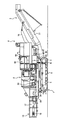
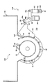
- FIG. 1 is a side view showing the entire structure of the self-propelled crusher according to the first embodiment of the present invention
- FIG. 2 is a plan view thereof
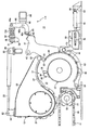
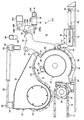
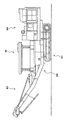
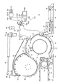
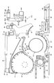
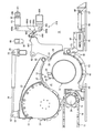
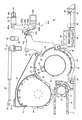
- 3 to 5 are perspective side views showing a detailed structure in the vicinity of the crushing device 12 provided in the self-propelled crusher shown in FIG. 1, and FIG. 4 shows the case where the housing is rotating, and FIG. 5 shows the case where the housing is in the open position.
- the directions corresponding to the left and right in FIGS. 1 and 2 are the rear and front of the self-propelled crusher, or one and the other.
- the self-propelled crusher of the present embodiment includes a traveling body 1 that enables self-running, a crushing function component 2 that crushes an object to be crushed provided on the traveling body 1, It is schematically configured by a discharge conveyor 3 that transports the crushed material crushed by the crushing function component 2 and discharges it outside the machine, a power unit (power unit) 4 equipped with an engine that is a power source of each mounted device, and the like. .
- the traveling body 1 includes a track frame 5, drive wheels 6 and driven wheels 7 provided at both front and rear ends of the track frame 5, and a drive device (travel hydraulic motor) 8 in which an output shaft is connected to the shaft of the drive wheel 6. And a crawler belt (an endless track crawler belt) 9 wound around the driving wheel 6 and the driven wheel 7.
- a main body frame 30 is provided on the track frame 5, and the main body frame 30 supports the crushing function component 2, the discharge conveyor 3, the power unit 4, and the like.
- the crushing function constituent unit 2 includes a hopper 10 that receives an object to be crushed, a feed conveyor 11 (see FIG. 2) as a means for conveying the object to be crushed accommodated in the hopper 10, and the feed conveyor 11.
- a crushing device 12 (see FIGS. 3 to 5) that crushes the material to be crushed introduced by the crushing device, and a pressure roller device 13 that presses the material to be crushed introduced into the crushing device 12 before the crushing device 12 against the feed conveyor 11. (See FIGS. 3 to 5).
- the feed conveyor 11 includes a sprocket-like drive wheel 15 provided on the crushing rotor 32 side (crusher front side), which will be described later, a driven wheel (not shown) provided on the opposite side (crusher rear side), and the conveying direction thereof. It is provided between a drive wheel 15 and a driven wheel provided at both ends, and a transport body (transport belt, chain belt) 16 arranged in a plurality of rows (for example, 4 rows, see FIG. 2) in the width direction. Yes.
- the driven wheel is supported by a bearing 18 (see FIG. 1) provided at the rear portion of the side wall body 17 (see FIG. 1) of the hopper 10, and the drive wheel 15 is a side frame of the crushing device 12 provided on the front side of the side wall body 17.
- 19 (see FIG. 3) is supported by a bearing 84.
- the feed conveyor 11 extends substantially horizontally from the lower part of the hopper 10, that is, from the inside of the side wall body 17 of the hopper 10 to the vicinity of the crushing rotor 32 (described later), and the side frame 19 of the hopper 10 and the crushing device 12. It is stored inside.
- the rotating shaft 20 of the driving wheel 15 of the feed conveyor 11 is connected to an output shaft of a driving device (not shown) provided on the outer side in the width direction than the bearing through a coupling or the like.
- the feed conveyor 11 circulates and drives the carrier 16 between the drive wheel 15 and the driven wheel by rotating the drive wheel 15 with a drive device (not shown).
- the pressure roller device 13 is provided so as to be close to the rear side of the crushing rotor 32 (described later) and on the upper portion of the feed conveyor 11 so as to face the transport surface thereof, and is transported on the feed conveyor 11.
- the crushed material is introduced toward the crushing rotor 32 while pressing the material to be crushed from above.
- the pressing roller device 13 has a rotating shaft 22 pivotally supported by a bearing (not shown) provided on the side frame 19 above the crushing device 12, so that it can rotate in a vertical plane (in FIG. 3).
- a support member (arm) 23 supported so as to be swingable in the vertical direction, and a presser roller 24 rotatably provided to the support member 23 are provided.
- the support member 23 includes a rotating shaft 22 at one end, and a pressing roller 24 at the other end (one end on the front end side).
- the lower end surface of the support member 23 (the end surface facing the upper portion of the crushing rotor 32) is curved in an arc shape, and this curved portion includes a curved plate constituting a part of the crushing chamber 31 described later. 27 is attached.
- the pressing roller 24 mounting portion of the support member 23 is formed in an arc shape having a diameter smaller than the diameter of the pressing roller 24, and the outer peripheral surface of the pressing roller 24 protrudes from the support member 23.
- the dimension of the pressing roller 24 in the width direction (the direction orthogonal to the paper surface in FIG. 3) is set to be equal to or larger than the width of the conveying surface of the feed conveyor 11.
- the presser roller 24 has a drive device (not shown) built in its body, and this drive device has a peripheral speed substantially the same as the transfer speed of the object to be crushed on the transfer surface of the feed conveyor 11.
- the object to be crushed on the feed conveyor 11 that is rotationally driven and pressed down is introduced into the crushing chamber 31 in cooperation with the feed conveyor 11.
- the hydraulic cylinder 28 is rotatably connected to a bracket 29 whose bottom end is fixed to the side frame 19 via a pin 53, and its rod end is rearward of the support member 23 (left side in FIG. 3). It is connected to a bracket 54 provided at the distal end portion via a pin 82 so as to be rotatable.
- the pressing roller device 13 can be rotated around the rotation shaft 22 and can be raised and lowered with respect to the feed conveyor 11 (in other words, separated or close to the crushing device 12). It is like that.
- the crushing device 12 is located at a substantially central portion in the longitudinal direction of the main body frame 30 (see FIG. 1), and as shown in FIG. 3, a crushing rotor 32 that rotates at high speed in the crushing chamber 31 and the radial direction of the crushing rotor 32
- An anvil (fixed blade) 33 provided on the outside and a protection mechanism 14 for protecting the anvil 33, the crushing rotor 32, and the like are provided.
- the forward rotation direction of the crushing rotor 32 (clockwise direction in FIG. 3, crushing) from the part to which the material to be crushed is supplied by the feed conveyor 11 and the press roller 24 (the rear part of the crushing device 12).
- the curved plate 27, the anvil 33, the curved plate 39, and the screen (sieving member) 40 are provided so as to surround the crushing rotor 32 in the material distribution direction).
- the crushing chamber 31 which is a cylindrical space around which crushing pieces circulate around the crushing rotor 32 is defined by 40 or the like.
- the crushing rotor 32 is rotatably supported by a bearing (not shown) provided on a side frame 19 of the crushing device 12 or a support member (not shown) provided on the main body frame 30.
- a plurality of support members 34 and a crushing bit (impact plate or crushing blade) 35 attached with bolts 38 on the front side in the forward direction of each support member 34 are provided.
- the crushing bit 35 is disposed so that the blade surface thereof precedes the support member 34, and the crushing bit 35 hits the object to be crushed.
- a set of crushing bits 35, a support member 34, and bolts 38 are shown as representatives.
- the anvil 33 has a collision surface 33a on which a material to be crushed introduced into the crushing chamber 31 collides, and collides with a crushed piece (a material to be crushed) that circulates in the crushing chamber 31 as the crushing rotor 32 rotates. It is attached via a support member 51 on the upstream side in the forward rotation direction of the crushing rotor 32 with respect to the attachment portion of the curved plate 39 in the housing 41 so that the surface 33a faces.
- the support member 51 is attached to the housing 41 with a bolt or the like (not shown).
- the housing 41 holds the anvil 33 on the crushing chamber 31 side, and has a rotating shaft 42 supported by a bearing (not shown) provided on the side frame 19 above the rotating shaft 22 of the pressing roller device 13 described above.
- a hooking portion 46 is supported at the fulcrum so as to be pivotable in the front-rear direction, and protrudes forward at a front end portion extending forward from the pivot shaft 42.
- the housing 41 is formed such that the distance from the rotation shaft 42 to the anvil 33 and the length (distance) to the hooking portion 46 are substantially equal.
- the rotation shaft 42, the anvil 33, and the hooking portion 46 of the housing 41 correspond to the fulcrum, the power point, and the action point in the principle of the lever, respectively, and therefore, the load almost the same as the load applied to the anvil 33 (power point) is applied. It acts on the part 46 (action point).
- the hanging portion 46 of the housing 41 is supported by a holding portion of a protective device 14 (described later) provided on the inner wall surface of the side frame 19, and the anvil 33 is connected to the object to be crushed in the crushing chamber 31. It is held in the opposite closed position (position shown in FIG. 3).
- the screen 40 is provided on the downstream side in the crushed material distribution direction of the curved plate 39 and on the outer side in the radial direction of the crushing rotor 32, and is curved substantially along a circle concentric with the crushing rotor 32. Further, the screen 40 has a plurality of discharge holes (not shown) that penetrate from the inner diameter surface facing the crushing rotor 32 to the opposite surface and discharge the crushed material to the outside of the crusher. The crushed material that has become smaller than the diameter R of the discharge hole (not shown) is discharged out of the crusher.
- a frame-type screen support member (screen holder) 63 for holding the screen 40 at the outer peripheral side position of the crushing rotor 32 is provided below the crushing rotor 32.
- the screen support member 63 has a rear end portion fixed to a side member 19 or a support member (not shown) provided on the side frame 19 or the main body frame 30 via a rotation shaft 64, and rotates up and down around the rotation shaft 64. It is configured to move.
- a link mechanism 69 that moves the screen support member 63 forward and backward with respect to the crushing rotor 32 is provided at the front end of the screen support member 63.
- the link mechanism 69 is provided at a bottom end of the hydraulic cylinder 66 connected to a bracket 67 fixed to the side frame 19 via a pin 68 so as to be rotatable, and at a rod end of the hydraulic cylinder 66.
- a slider 70 that moves back and forth as the cylinder 66 expands and contracts, a front end portion of the screen support member 63, and an arm 72 that is rotatably connected to both ends of the slider 70 are provided.
- the member 63 is lowered from the state shown in FIG.
- the state shown in FIG. 3 is that during the crushing operation, and the link mechanism 69 holds the posture of the screen support member 63 by extending the hydraulic cylinder 66.
- the hydraulic cylinder 66 When the hydraulic cylinder 66 is shortened, the other end portion of the arm 72, that is, the end portion on the slider 70 side is translated in parallel with the slider 70 in the retracting direction (right direction in FIG. 3) of the cylinder 66, and the screen support member 63 is moved. It pivots downward about the pivot shaft 64.
- the screen support member 63 is lowered in this way, the screen 40 placed on the screen support member 63 can be pulled out sideways from a notch (not shown) formed in the lower part of the side surface frame 19. The screen 40 can be replaced.
- the discharge side (front side) portion is suspended and supported by a support member 75 provided so as to protrude from the power unit 4. Further, the opposite side (rear side) portion is supported by being suspended from the main body frame 30 via the support member 36.
- the discharge conveyor 3 passes from below the crusher 12 below the power unit 4 and is disposed so as to be inclined upward from the lower side of the power unit 4 to the front side of the self-propelled crusher.
- the discharge conveyor 3 is mounted on a frame 77 and a conveyor belt (not shown) wound between drive wheels (not shown) and driven wheels (not shown) provided at both ends of the frame 77 in the longitudinal direction. And a conveyor cover 78 provided.
- a drive wheel (not shown) of the discharge conveyor 3 is connected to an output shaft of a drive device (hydraulic motor for discharge conveyor) 79 provided on the outer side in the width direction than the bearing through a coupling or the like.
- a drive device hydraulic motor for discharge conveyor
- the power unit 4 is mounted on the other end portion in the longitudinal direction of the main body frame 30 via a support member 80.
- a driver's seat 81 is provided in a section on the rear side and one side in the width direction (lower side in FIG. 2) of the power unit 4, and an operation lever 85 for driving operation is provided in front of the driver's seat 81. It has been.
- an operation panel 83 is provided on the lower side surface of the driver's seat 81 in the self-propelled crusher for performing operations other than the traveling operation, setting, monitoring, and the like.
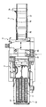
- FIG. 1 Details of the above-described protective device 14 will be described with reference to FIGS. 3 to 5, 6 and 7.
- FIG. 1
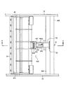
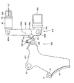
- FIG. 6 is a plan view showing the protective device 14 and the housing 41 shown in FIG. 3 with the peripheral components extracted
- FIG. 7 is a perspective plan view showing details of the housing 41 and the lever 90 shown in FIG. 6 and 7, the left and right directions correspond to the rear and front directions of the self-propelled crusher shown in FIGS.
- the protection device 14 is disposed along the body width direction (vertical direction in FIG. 6), and is provided with a lever bracket 96 provided on a lever support member 94 fixed to the side frames 19 and 19 at both ends, and a pin 90b on the lever bracket 96.
- a lever 90 rotatably provided via a pin, a roller 95 rotatably provided at one end on the housing 41 side of the lever 90 via a pin 90c, and an end opposite to the housing 41 of the lever 90.
- a rod 91 rotatably provided via a pin 90a, an elastic member 93 interposed between the lever 90 and the stopper support member 48 through the rod 91, and between the lever support member 94 and the elastic member 93. And an inserted shim 92.
- the lever support member 94 is disposed in front of the housing 41.
- the lever bracket 96 is provided at substantially the center of the lever support member 94 whose both ends are fixed to the side frames 19, 19, that is, at a position corresponding to the hanging portion 46 of the housing 41. Is provided to protrude.
- the lever 90 has an L-shape bent in the direction of the housing 41 (left direction in FIG. 3).
- the lever 90 has a lever bracket via a pin 90b at a position where the distance between one end on the pin 90a side (rod 91 side) and the pin 90b is longer than the distance between one end on the pin 90c side (housing 41 side) and the pin 90b.
- 96 is rotatably connected. Therefore, the force (rotational force) applied to the one end on the pin 90a side corresponding to the power point of the lever principle in the rotation direction is passed through the pin 90b corresponding to the fulcrum, so that the force on the pin 90c side corresponding to the action point is applied. At one end, a greater force (rotational force) is obtained.
- a portion of the lever 90 that is closer to the pin 90 c than the pin 90 b is provided at one end of the housing 41, and serves as a holding portion that holds the hanging portion 46 of the housing 41 and holds the anvil 33 facing the crushing chamber 31.
- a roller 95 is rotatably provided via a pin 90c at a position where the holding portion comes into contact with the engaging portion 46. When the hooking portion 46 moves relative to the holding portion of the lever 90, the roller 95 rolls on the hooking portion 46 to reduce the frictional force generated between the holding portion and the hooking portion 46.
- the rod 91 is rotatably provided at one end opposite to the housing 41 of the lever 90 via a pin 90 a and is fitted into a stopper support member 48 fixed to the side frames 19 and 19. .
- the stopper support member 48 is disposed above the housing 41 (upward in FIG. 3), and the rod 91 extends from the pin 90a of the lever 90 in the direction of the stopper support member 48.
- the elastic member 93 is an elastic member such as a rubber spring or a urethane spring, and is interposed between the lever 90 and the stopper support member 48 through the rod 91.
- the shim 92 is inserted between the stopper support member 48 and the elastic member 93, and is fixed so as not to drop off by a bolt or the like (not shown).
- the shim 92 is urging force adjusting means for adjusting the urging force of the elastic member 93 to the lever 90.
- the rod 91 and the elastic member 93 urge the lever 90 with the set urging force, and when the rotational force applied to the lever 90 through the holding portion exceeds the urging force, the lever 90 is rotated to move the anvil.
- the urging means for allowing the 33 to move away from the crushing chamber 31 is configured, and the shim 92 constitutes an urging force adjusting means for adjusting the urging force of the elastic member 93.
- the housing 41 is closed by the holding portion of the lever 90 of the protective device 14 provided on the side frame 19 during the crushing operation (in the state shown in FIG. 3). That is, the anvil 33 is fixed and held in such a posture that it is disposed in the vicinity of the rotation trajectory of the crushing bit 35.
- the roller 95 provided in the holding portion of the lever 90 pushes the hooking portion 46 of the housing 41 rearward by the urging force of the elastic member 93 transmitted through the lever 90.
- the lever 90 rotates and the roller 95 provided in the holding portion is moved. Move forward.
- the hanging portion 46 of the housing 41 is pushed in from above by, for example, a cylinder, a manual jack, or manual operation.
- the posture of the housing 41 that is, the position of the anvil 33 with respect to the crushing chamber 31 can be returned to the state shown in FIG.
- the stopper support member 48 fixed to the side frame 19 is provided with a stopper 50, and the stopper 50 limits the rotation range of the housing 41 in the opening direction (counterclockwise direction in FIG. 3). Interference between the housing 41 and other components is prevented.
- the object to be crushed When an object to be crushed is put into the hopper 10 by a heavy machine (hydraulic excavator or the like) equipped with an appropriate work tool such as a grapple, the object to be crushed is placed on the conveyor belt 16 of the feed conveyor 11 and circulated. 16 is conveyed toward the crushing device 12.
- the press roller 24 rides on the object to be crushed, and the object to be crushed is pressed against the conveying surface of the feed conveyor 11 by its own weight.
- the presser roller 24 introduces the material to be crushed into the crushing chamber 31 in cooperation with the feed conveyor 11 while the material to be crushed is sandwiched between the pressure roller 24 and the feed conveyor 11.
- the object to be crushed protrudes into the crushing chamber 31 in a cantilevered manner with the portion sandwiched between the presser roller 24 and the feed conveyor 11 as a fulcrum.
- the crushing bit 35 of the crushing rotor 32 that rotates at high speed collides with the crushing object protruding into the crushing chamber 31 from below, whereby the crushing object is roughly crushed (primary crushing).
- the fragments to be crushed and thus splashed into the crushing chamber 31 collide with the anvil 33 and are further crushed by the impact force.
- the crushed pieces circulate in the crushing chamber 31 with the rotation of the crushing rotor 32 and collide with the crushing bit 35, the anvil 33, the inner wall surface of the crushing chamber 31, and the like (secondary crushing).
- the crushed pieces that have been pulverized to pass through the discharge holes of the screen 40 sequentially pass through the screen 40 and are discharged from the crushing chamber 31.
- the crushed material discharged from the crushing chamber 31 falls on the discharge conveyor 3, is transported by the discharge conveyor 3, and is discharged outside the machine.
- the protection device 14 is rotated by the lever 90 of the protection device 14 in the opening direction (counterclockwise in FIG. 3). As shown in FIG. 5, the housing 41 and the anvil 33 are pivoted about the pivot shaft 42 with respect to the side frame 19 and retreated from the crushing chamber 31. Thus, damage to each part of the crusher including the anvil 33 is prevented.
- the impact force of the housing 41 jumping up when the housing 41 is retreated is absorbed by the stopper 50. Further, the housing 41 returns to the original position (closed position) by its own weight. However, when the retracting of the housing 41 is detected by a position sensor (not shown), the self-propelled crusher stops the crushing operation of the object to be crushed, that is, the conveyance of the object to be crushed by the conveyor 11 or the like, the rotation of the crushing rotor 32, etc. To do.
- the hooking portion 46 is provided on the opposite side of the housing 41 from the anvil 33, the hooking portion 46 is held by the holding portion of the lever 90, and the operation of the hooking portion 46 is controlled by the lever. 90, the biasing means and the lever 90 can be rotated even if a foreign object such as a stone or metal is caught between the crushing bit 35 and the anvil 33. As a result, the housing 41 that supports the anvil 33 rotates, and the anvil 33 is retracted from the crushing chamber 31.
- the holding portion of the lever 90 presses the hooking portion 46 of the housing 41 in accordance with the hardness of the object to be crushed.
- the frequency with which the housing 41 is pivoted and retracted during the crushing operation can be adjusted by adjusting the force (hereinafter referred to as the holding force) that holds the posture 33 facing the crushing chamber 31.
- the holding force is set large by adjusting the urging force, and the object to be crushed Can be more reliably crushed.
- the crushing device tends to fall into an overload state, so the holding force can be set small by adjusting the biasing force. And the damage of the crushing device is suppressed by making the anvil 33 easy to retreat. In this way, it is possible to set a holding force in consideration of both the suppression of damage to the bearings and structures of the crushing rotor 32 and the securing of the crushing force of the object to be crushed, and the crushing operation can be performed efficiently.
- the distance from the rotation shaft 42 of the housing 41 to the anvil 33 and the length to the hanging portion 46 are formed to be substantially equal, the load applied to the hanging portion 46 and the load applied to the anvil 33 are substantially the same. Therefore, it is easy to set the urging force of the urging means in consideration of the load applied to the anvil 33.
- the length (distance) from the rotation shaft 42 to the hanging portion 46 with respect to the length from the rotation shaft 42 to the anvil 33 of the housing 41 May be shortened.
- the protection device 14 can provide a margin for the holding force for holding the hanging portion 46 of the housing 41. Therefore, effects such as downsizing of the protective storage 14 can be expected.
- the case where a rubber spring or a urethane spring is used as the elastic member 93 of the protection device 14 has been described as an example.
- the present invention is not limited to this.
- a coil spring may be used. Even in this case, the same effect as the above-described embodiment can be obtained.
- the case where one protective device 14 is used has been described as an example.
- the present invention is not limited to this.
- the protective device 14 may be provided at both ends of the lever support member 94.
- the urging force adjusting means for adjusting the urging force of the elastic member 93 with respect to the lever 90 is configured to adjust the urging force with the number and thickness of shims, but is not limited to this.
- an adjustment screw is provided, The biasing force may be adjusted by turning.
- the elastic member 93 may be replaced with one having a different elastic force.
- This embodiment shows a case where a protection device 214 is used instead of the protection device 14 of the crushing device 12 shown in the first embodiment.
- members equivalent to those in the first embodiment are denoted by the same reference numerals, and description thereof is omitted as appropriate.
- FIG. 10 to 12 are perspective side views showing a detailed structure in the vicinity of the crushing device 12 according to the present embodiment.
- FIG. 10 shows a case where the housing is in the closed position
- FIG. 11 shows a case where the housing is rotating.
- Reference numeral 12 denotes a case where the housing is in the open position.
- the directions corresponding to the left and right in FIG. 1 are the rear and front of the self-propelled crusher, or one or the other.
- the protection device 214 includes a lever bracket 296 provided in a lever support member 294 that is disposed along the body width direction (the direction orthogonal to the paper surface in the drawing) and is supported by the side frame 19 at both ends.
- a lever 290 having one end pivotably provided on the lever bracket 296 via a pin 290b, and a rod 91 pivotally provided on one end opposite to the lever bracket 296 of the lever 290 via a pin 290a.
- a roller 295 rotatably provided via a pin 290c on a convex portion 290d provided on the housing 41 side of the body portion of the lever 290, and arranged along the body width direction (the direction perpendicular to the paper surface in the drawing).
- the lever support member 294 is disposed in front of the housing 41.
- the pin 290c of the lever 290 is arranged so that the distance between the one end on the pin 290b side where the lever bracket 296 is provided and the pin 290c is shorter than the distance between the one end on the pin 290a side where the rod 91 is provided and the pin 290c. Yes.
- the force applied to the one end on the pin 290a side, which is the power point, in the rotation direction becomes a larger force at the pin 290c, which is the point of action, via the pin 290b, which is the fulcrum.
- the lever 290 has a convex portion 290 d on the housing 41 side of the trunk portion, and the convex portion 290 d holds the hanging portion 46 of the housing 41 and holds the anvil 33 in a posture facing the crushing chamber 31. It has the function of A roller 295 is rotatably provided via a pin 290c at a contact position of the holding portion 290d with the engaging portion 46. When the hooking portion 46 moves relative to the holding portion 290d of the lever 290, the roller 295 rolls on the hooking portion 46 to reduce the frictional force generated between the holding portion 290d and the hooking portion 46.
- the rod 91 is rotatably provided at one end of the lever 290 opposite to the lever bracket 296 via a pin 290a, and is fitted into a rod support member 248 fixed to the side frames 19, 19. Yes.
- the rod support member 248 is disposed in front of the housing 41 and below the lever support member 294 (downward in FIG. 10), and the rod 91 extends from the pin 290a of the lever 290 toward the rod support member 248. is doing.
- the housing 41 In the crushing operation (in the state shown in FIG. 10), the housing 41 is closed by the holding portion 290d of the lever 290 of the protective device 214 provided on the side frame 19, that is, the anvil 33 is crushed.
- the bit 35 is fixed and held in such a posture as to be arranged in the vicinity of the rotation trajectory.
- the roller 295 provided in the holding portion 290d of the lever 290 pushes the hooking portion 46 of the housing 41 rearward by the urging force of the elastic member 93 transmitted via the lever 290.
- the housing 41 rotates about the rotation shaft 42, the anvil 33 is retracted from the crushing chamber 31, and damage to each part of the crusher including the anvil 33 is prevented.
- the hanging portion 46 of the housing 41 is pushed in from above by, for example, a cylinder, a manual jack, or manual operation.
- the posture of the housing 41 that is, the position of the anvil 33 with respect to the crushing chamber 31 can be returned to the state shown in FIG.
- the stopper support member 48 fixed to the side frame 19 is provided with a stopper 50, and the stopper 50 limits the rotation range of the housing 41 in the opening direction (counterclockwise direction in FIG. 10). Interference between the housing 41 and other components is prevented.
- the protection device 214 rotates the lever 290 of the protection device 214 in the opening direction (counterclockwise direction in FIG. 3) and the holding portion 290d. Since the structure is such that the restraint of the hanging portion 46 is released, as shown in FIG. 12, the housing 41 and the anvil 33 rotate about the rotation shaft 42 with respect to the side frame 19 and retreat from the crushing chamber 31. Thus, damage to each part of the crusher including the anvil 33 is prevented.
- the impact force of the housing 41 jumping up when the housing 41 is retreated is absorbed by the stopper 50. Further, the housing 41 returns to the original position (closed position) by its own weight. However, when the retracting of the housing 41 is detected by a position sensor (not shown), the self-propelled crusher stops the crushing operation of the object to be crushed, that is, the conveyance of the object to be crushed by the conveyor 11 or the like, the rotation of the crushing rotor 32, etc. To do.
- the protection device for the crushing device shown in the first embodiment is used for a tab-type self-propelled crusher.
- members equivalent to those in the first embodiment are denoted by the same reference numerals, and description thereof is omitted as appropriate.
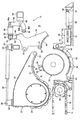
- FIG. 13 is a side view showing the overall structure of a self-propelled crusher according to a third embodiment of the present invention
- FIG. 14 is a plan view thereof
- FIGS. 15 and 16 are self-propelled crushers shown in FIG.
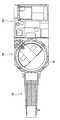
- FIG. 15 is a perspective side view showing a detailed structure in the vicinity of the crushing device 312 provided in the machine.
- FIG. 15 shows a case where the housing 41 is in the closed position
- FIG. 16 shows a case where the housing 41 is in the open position.
- the directions corresponding to the left and right in FIG. 13 are the rear and front of the self-propelled crusher, or one and the other.
- the self-propelled crusher includes a traveling body 301 that enables self-running, a crushing function component 302 that crushes the object to be crushed provided on the traveling body 301, It is schematically configured by a discharge conveyor 303 that conveys the crushed material crushed by the crushing function component 302 and discharges it outside the machine, a power unit (power unit) 304 including an engine that is a power source of each mounted device, and the like. .
- the crushing function component 302 is provided above the self-propelled crusher (upward in FIG. 1), and has a substantially cylindrical shape for receiving and storing the object to be crushed from the upper part of the opening.
- Type storage means (rotary tab) 99 and a crushing device 312 provided below the rotary tab 99 and crushing objects to be crushed introduced by the rotary tab 99. ing.
- the rotary tab 99 is rotationally driven by a hydraulic motor (not shown) to sequentially introduce a large number of parts to be shredded therein into the crushing device 312.
- the crushing device 312 includes a crushing rotor 32 that rotates at a high speed in the crushing chamber 331, an anvil (fixed blade) 33 provided on the radially outer side of the crushing rotor 32, and the anvil 33 and crushing And a protection mechanism 314 that protects the rotor 32 and the like.
- the forward rotation direction of the crushing rotor 32 (the clockwise direction in FIG. 15, the crushing material distribution direction) from the portion (the upper portion of the crushing device 312) where the material to be crushed is supplied by the rotary tab 99 ),
- the anvil 33, the curved plate 39, and the screen (sieving member) 40 are provided so as to surround the crushing rotor 32.
- the crushing chamber 331 that is a circular cylindrical space is defined.
- the housing 341 holds the anvil 33 on the crushing chamber 331 side and is supported by a bearing (not shown) provided on the side frame 319 of the self-propelled crusher below the rotary tab 99 described above.
- the moving shaft 342 is supported so as to be pivotable in the front-rear direction, and a protrusion 46 is provided at the end of the front obliquely lower side (lower right in the figure) as viewed from the rotating shaft 342.
- the hanging portion 46 of the housing 341 is supported by a holding portion (described later) of a protection device 314 (described later) provided on the inner wall surface of the side frame 319, and the anvil 33 is covered in the crushing chamber 31.
- the protective device 314 includes a lever bracket 96 provided on a lever support member 94 that is disposed along the body width direction (perpendicular to the paper surface in FIG. 15) and that is fixed to the side frame 319 at both ends, and a pin 90b is provided on the lever bracket 96.
- a lever 90 that can be rotated via a roller 90, a roller 95 that is rotatably provided at one end on the housing 341 side of the lever 90 via a pin 90c, and a machine body width direction (perpendicular to the paper surface in FIG. 15).
- a rod support member 348 having both ends fixed to the side frame 319, a rod 91 provided at one end opposite to the housing 341 of the lever 90 via a pin 90a, and a rod 91
- An elastic member 93 interposed between the lever 90 and the rod support member 348, and inserted between the lever support member 94 and the spring 93.
- a shim 92 is interposed between the lever 90 and the rod support member 348, and inserted between the lever support member 94 and the spring 93.
- a portion of the lever 90 that is closer to the pin 90 c than the pin 90 b is provided at one end of the housing 41, and serves as a holding portion that holds the hanging portion 46 of the housing 41 and holds the anvil 33 facing the crushing chamber 31. .
- the lever support member 94 is disposed on the lower front side of the housing 41 (the lower right direction in FIG. 15).
- the lever bracket 96 is provided at substantially the center of the lever support member 94 whose both ends are fixed to the side frame 319, that is, at a position corresponding to the hanging portion 46 of the housing 341, and above the lever support member 94 (in FIG. 15). It protrudes in the upward direction.
- the rod 91 is rotatably provided at one end opposite to the housing 41 of the lever 90 via a pin 90a, and is fitted into a rod support member 348 fixed to the side frame 319.
- the rod support member 348 is disposed on the opposite side of the housing 341 with respect to the lever support member 94, and the rod 91 extends from the pin 90 a of the lever 90 in the direction of the rod support member 348.
- the material to be crushed introduced into the crushing chamber 331 collides with the crushing bit 35 of the crushing rotor 32 that rotates at high speed, and the material to be crushed is roughly crushed. Finely crushed. Thereafter, the crushed pieces circulate in the crushing chamber 331 with the rotation of the crushing rotor 32 and collide with the crushing bit 35, the anvil 33, the inner wall surface of the crushing chamber 331, and the like, and are crushed. Then, the crushed pieces that have been pulverized to pass through the discharge holes of the screen 40 sequentially pass through the screen 40 and are discharged from the crushing chamber 331.
- the crushed material discharged from the crushing chamber 331 falls on the discharge conveyor 303, is conveyed by the discharge conveyor 303, and is discharged outside the apparatus.
- the protection device 314 rotates the lever 90 of the protection device 314 in the opening direction (counterclockwise direction in FIG. 15) and is hooked by the holding portion. Since the portion 46 is unconstrained, the housing 341 and the anvil 33 rotate about the rotation shaft 342 with respect to the side frame 319 and retreat from the crushing chamber 331 as shown in FIG. This prevents damage to each part of the crusher.
- the jumping impact force of the housing 341 when the housing 341 is turned and retracted is absorbed by a stopper (not shown).
- the housing 341 returns to the original position (closed position) by its own weight.
- the self-propelled crusher performs crushing operation of the object to be crushed, that is, carrying the object to be crushed by rotating the rotary tab 99, Stop rotation etc.
- the protection device of the first embodiment is used in a tab-type crusher
- the present invention is not limited to this, and the protection device of the second embodiment is used. It may be used. Even in this case, the same effect as the first embodiment can be obtained.
- the hook portion 446 and the protection device 414 are used instead of the hook portion 46 and the protection device 14 shown in the first embodiment, and the hook portion 446 and the hook portion 446 are pressed.
- the frequency at which the housing 441 rotates and the anvil 33 retracts from the crushing chamber 31 is adjusted. .
- FIGS. 17 to 19 are perspective side views showing a detailed structure in the vicinity of the crushing device 12 provided in the self-propelled crusher according to the present embodiment, and FIG. 17 shows the position of the housing 441 at the time of crushing work.
- FIG. 18 shows a case where the housing 441 is rotating from the closed position to the open position
- FIG. 19 shows a case where the housing 441 is in the open position where the anvil 33 is retracted.
- the direction corresponding to the left and right in FIGS. 1 and 2 is the rear / front of the self-propelled crusher, or one / the other.
- the housing 441 holds the anvil 33 on the crushing chamber 31 side, and is supported by a bearing (not shown) provided on the side frame 19 above the rotating shaft 22 of the pressing roller device 13 described above.
- a pivot portion 446 (described later) is provided at a front end portion that is supported on the pivot shaft 42 that is pivotable in the front-rear direction and extends forward as viewed from the pivot shaft 42.
- the housing 441 is formed so that the distance (distance) from the pivot shaft 42 that is a fulcrum to the anvil 33 that is a force point and the length (distance) to the hook portion 446 that is an action point are substantially equal.
- a load having the same magnitude as that of the load is applied to the hanging portion 446.
- the length (distance) from the rotation shaft 42 to the hanging portion 446 is increased with respect to the length from the rotation shaft 42 to the anvil 33 of the housing 441. Conversely, it may be shortened.
- the hanging portion 446 of the housing 441 is supported by a holding portion 490d (described later) of the protective device 414 provided on the inner wall surface of the side frame 19, and the anvil 33 is crushed in the crushing chamber 31. Is held in a closed position (position shown in FIG. 17).
- a similar load is also applied to the protective device 414, and the holding portion 490d of the protective device 414 moves forward to move to the hanging portion 446 of the housing 441.
- the restraint is released, the housing 441 rotates about the rotation shaft 42 (see FIG. 18), and the anvil 33 rotates to the open position (the position shown in FIG. 19) withdrawn from the crushing chamber 31.
- the amount of forward movement of the holding portion 490d necessary for releasing the restraint of the hook portion 446 is referred to as a hook amount.
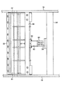
- FIG. 20 is a side view showing the housing 441 in the closed position, its hook portion 446, and the protection device 414 extracted with the peripheral configuration
- FIG. 21 shows the housing 441 and the protection device 414 shown in FIG. 20 extracted with the peripheral configuration
- FIG. 22 is a cross-sectional view taken along line AA in FIG. Note that the left and right directions in FIG. 21 correspond to the rear and front directions of the self-propelled crusher shown in FIGS. 1 and 2.
- the hook portion 446 includes a latch 447 that comes into contact with the holding portion 490d of the protection device 414, a case 452 that holds the latch 447 in a state in which a contact portion with the holding portion 490d is protruded, and a case And a base portion 449 for fixing 452 to the housing 441.
- the case 452 has an opening for projecting the latch 447 on the protective device 414 side, and the opposite side, that is, the back side of the opening in the case 452 (hereinafter referred to as the back side) is rotated by the housing 441. Further, the opening side is inclined with respect to the turning and retracting direction so that the opening side is farther from the turning shaft 42 that is the turning center of the housing 441 than the back side. That is, when the housing 441 is in the closed position (see FIG. 20), the back side is directed rearward and upward (in the leftward and upward direction in FIG. 20), and the opening side is inclined in the forward and downward direction (in FIG. 20). It is arranged toward the diagonally lower right). Of the wall surfaces extending to the opening side of the case 452, the wall surface on the housing 441 side is formed longer than the wall surface on the holding portion 490d side.
- the latch 447 is slidable (movable back and forth) along the wall surface of the case 452 on the housing 441 side and the holding portion 490 d side so as to be slidable (movable back and forth), and the latch 447 is attached to the case 452.
- the amount of protrusion from the opening of the case 452 is adjusted by sliding.
- One end of the latch 447 on the case 452 side of the opening is curved from the side surface of the case 452 on the holding portion 490d side to the end surface on the opening side (surface formed in the sliding direction).
- the latch 447 When the housing 441 is in the closed position, the latch 447 is in contact with the holding portion 490d in the lateral direction with respect to the sliding direction of the protruding portion, and the latch 447 is pressed against the wall surface of the case 452 on the housing 441 side. At this time, the force acting on the latch 447 from the holding portion 490d is perpendicular to the slidable direction of the latch 447, and thus a frictional force acts between the latch 447 and the wall surface of the case 452 on the housing 441 side. Therefore, sliding of the latch 447 with respect to the case 452 due to the latch 447 being pushed by the holding portion 490d is suppressed.
- the force applied to the latch 447 from the holding portion 490d causes a component perpendicular to the sliding direction of the latch 447 to cause the latch 447 and the case 452.
- a frictional force acts between the housing 441 and the wall surface on the housing 441 side.
- a bolt hole (not shown) provided with a female screw portion is provided on the inner peripheral portion at one end on the back side of the case 452 of the latch 447, and the male screw portion that is screwed into the bolt hole is provided on the body.
- Bolts 450 provided on the outer periphery of the portion (not shown) are inserted in a direction along the sliding direction of the latch 447.
- a plurality of (for example, three) bolts 450 are arranged side by side in the left-right direction (vertical direction in FIG. 21) at one end on the back side of the latch 447.
- the bolt 450 is slidably inserted in a through hole (not shown) provided at one end on the back side of the case 452, and a head portion 450 a having a larger diameter than the through hole has a case 452. It is arranged to be located outside. Thereby, the latch 447 and the bolt 450 slide integrally with respect to the case 452, and the slidable range of the latch 447 in the case 452 toward the opening is limited by the bolt 450.
- the slidable range in the direction of the opening of the latch 447 is determined by the distance between the head 450a of the bolt 450 and the latch 447. Therefore, the bolt 450 is rotated to adjust the amount of insertion of the latch 447 into the bolt hole. The distance is adjusted by changing the distance between the head 450a and the latch 447.
- a spring 451 interposed between the case 452 and the latch 447 through a bolt 450 is provided in the case 452.
- the spring 451 urges the latch 447 toward the opening side of the case 452 and is disposed at one end on the opening side of the slidable range.
- FIGS. 23 and 24 show a case where the housing 441 is changed from the open position to the closed position (returned).
- FIG. 23 is a diagram illustrating a state in which the latch 447 and the holding portion 490d are in contact with each other.
- FIG. 24 is a diagram illustrating a state in which the housing 441 is further moved from the position illustrated in FIG. 23 and 24, the latch 447 is slid to the back side of the case 452 as the housing 441 moves from the open position direction to the closed position direction.
- the amount of protrusion of the latch 447 toward the protection device 414 is temporarily reduced.
- FIG. 25 is a view showing a case where the latch 447 is disposed on the opening side of the case 452 with respect to the position of the latch 447 in FIG. 20 (hereinafter referred to as a reference position). It is a figure which shows the case where it has arrange
- the distance between the head 450a of the bolt 450 and the latch 447 is increased, the latch 447 is moved to the opening side of the case 452 with respect to the reference position, and the protrusion of the latch 447 to the protective device 414 side is performed.
- the amount of the hook portion 446 to be held with respect to the holding portion 490d is increased, and the force with which the holding portion 490d holds the latch 447 is increased.
- the distance between the head 450a of the bolt 450 and the latch 447 is shortened, the latch 447 is moved to the back side of the case 452 with respect to the reference position, and the latch 447 is moved to the protection device 414 side.
- the projection amount the amount of the hook portion 446 to be held with respect to the holding portion 490d is reduced, and the force with which the holding portion 490d holds the latch 447 is reduced.
- the protection device 414 includes a lever bracket 496 provided on a lever support member 494 that is disposed along the body width direction (in the direction orthogonal to the plane of the drawing in the drawing) and is supported by the side frame 19 at both ends, and one end pinned to the lever bracket 496.
- the roller 495 is rotatably provided on the convex portion 490d provided on the housing 441 side via a pin 490c, and is arranged along the machine body width direction (the direction orthogonal to the plane of the drawing in the drawing) and both ends are supported by the side frame 19.
- Rod support member 448 formed between the lever 490 and the rod support member 448 through the rod 91.
- a shim 92 interposed between the rod support member 448 and the elastic member 93.
- the lever support member 494 is disposed in front of the housing 441 (on the right side in FIG. 17).
- the pin 490c of the lever 490 is arranged such that the distance between the one end on the pin 490b side where the lever bracket 496 is provided and the pin 490c is shorter than the distance between the one end on the pin 490a side where the rod 91 is provided and the pin 490c. Has been. Therefore, the force applied to the one end on the pin 490a side that is the power point in the rotation direction becomes a larger force at the pin 490c that is the action point through the pin 490b that is the fulcrum.
- the lever 490 has a convex part 490 d on the housing 441 side of the trunk part, and the convex part 490 d holds the hook part 446 of the housing 441 and holds the anvil 33 in a posture facing the crushing chamber 31.
- a roller 495 is rotatably provided via a pin 490c at a position where the holding portion 490d contacts the engaging portion 446.
- the rod 91 is rotatably provided at one end of the lever 490 opposite to the lever bracket 496 via a pin 490a and is fitted into a rod support member 448 fixed to the side frames 19 and 19. Yes.
- the rod support member 448 is disposed in front of the housing 441 (rightward in FIG. 17) and above the lever support member 494 (upper side in FIG. 17), and the rod 91 extends from the pin 490a of the lever 490 to the rod support member. It extends in the direction of 448.
- the housing 441 In the crushing operation (in the state shown in FIG. 17), the housing 441 is closed by the holding portion 490 d of the lever 490 of the protection device 414 provided on the side frame 19, that is, the anvil 33 is crushed.
- the bit 35 is fixed and held in such a posture as to be arranged in the vicinity of the rotation trajectory.
- the roller 495 provided in the holding portion 490d of the lever 490 causes the latch 447 of the hanging portion 446 of the housing 441 to move backward (leftward in FIG. 17) by the urging force of the elastic member 93 transmitted through the lever 490. ).
- the force by which the hooking portion 446 pushes the roller 495 forward rightward in FIG.
- the stopper support member 48 fixed to the side frame 19 is provided with a stopper 50.
- the stopper 50 limits the range of rotation of the housing 441 in the opening direction (clockwise direction in FIG. 17). Interference between 441 and other components is prevented.
- the protection device 414 opens the lever 490 of the protection device 414 in the opening direction ( Rotating counterclockwise in FIG. 17), the roller 495 of the holding portion moves forward, the latch 447 of the hook portion 446 gets over the roller 495 of the holding portion, and the restraint of the housing 441 by the protective device 414 is released. Accordingly, the rotation of the housing 441 is allowed. In this case, as shown in FIG. 19, the housing 441 and the anvil 33 rotate around the rotation shaft 42 with respect to the side frame 19 and retreat from the crushing chamber 31 to prevent damage to each part of the crusher. .
- the impact load that serves as a reference for the anvil 33 to retreat from the crushing chamber 31 is adjusted by changing the protruding amount of the latch 447 with respect to the case 452.
- the holding force of the housing 441 by the holding portion 490d of the protection device 414 is increased by increasing the protrusion amount of the latch 447 and increasing the amount of the latch 447 applied to the holding portion 490d.
- the holding force of the housing 441 by the holding portion 490d of the protection device 414 is reduced by reducing the protrusion amount of the latch 447 and reducing the amount of the latch 447 applied to the holding portion 490d.
- the impact force of the housing 41 jumping up when the housing 41 is retreated is absorbed by the stopper 50. Further, the housing 41 returns to the original position (closed position) by its own weight. However, when the retracting of the housing 41 is detected by a position sensor or the like (not shown), the self-propelled crusher stops the crushing operation of the object to be crushed, that is, the carrying of the object to be crushed, the rotation of the crushing rotor 32, and the like.
- the state of the anvil 33 and the housing 41 is returned to the closed position by pushing the hooking portion 446 or the housing 441 from above with a cylinder, a manual jack, or manual operation. .
- the latch 447 is provided in the hook portion 446 of the housing 441 and the amount of the hook with respect to the holding portion 490d is adjusted by adjusting the position of the latch 447, the shim 92 and the elastic member 93 of the protection device 414 are replaced. Without this, it is possible to adjust the load that serves as a reference for the housing 441 to turn and retract.
- the latch 447 is pushed and slid by the holding portion 490d and protrudes from the case 452. Since the amount is temporarily reduced, the position of the anvil 33 can be returned with a smaller force.
- the elastic member of the protective device has been described as an example.
- the present invention is not limited to this.
- a coil spring may be used as the elastic member.
- the urging force adjusting means for adjusting the urging force with respect to the lever of the elastic member is configured to adjust the urging force by the number and thickness of the shims, but is not limited thereto.
- an adjusting screw is provided and this screw is turned. It is good also as a structure which adjusts urging
- the elastic member may be replaced with one having a different elastic force.
Abstract
Description
2 破砕機能構成部
3 排出コンベヤ
4 動力装置
5 トラックフレーム
10 ホッパ
11 送りコンベヤ
12 破砕装置
13 押圧ローラ装置
14 保護機構
15 駆動輪
16 搬送帯
19 側面フレーム
20 回転軸
22 回転軸
23 支持部材
24 押えローラ
27 湾曲板
28 油圧シリンダ
30 本体フレーム
31 破砕室
32 破砕ロータ
33 アンビル
34 支持部材
35 破砕ビット
36 支持部材
38 ボルト
39 湾曲板
40 スクリーン
41 ハウジング
42 回動軸
48 ストッパ支持部材
50 ストッパ
51 支持部材
63 スクリーン支持部材
64 回転軸
66 油圧シリンダ
69 リンク機構
70 スライダ
72 アーム
90 レバー
90a,90b,90c ピン
91 ロッド
92 シム
93 弾性部材
94 レバー支持部材
95 ローラ
96 レバーブラケット
Claims (11)
- 破砕機フレーム(19)と、
前記破砕機フレームに回転自在に支持された破砕ロータ(32)と、
前記破砕機フレームに回動可能に設けられたハウジング(41;341;441)と、
前記ハウジングに支持されて前記破砕ロータ周りの破砕室(31)に臨む固定刃(33)と、
前記ハウジングに対し前記破砕ロータと反対側に配置され、前記破砕機フレームに対して回動可能に設けられ、前記ハウジングを押さえて前記固定刃が前記破砕室に臨む姿勢に保持する保持部を設けたレバー(90;290;490)と、
前記レバーを設定の付勢力で付勢し、前記保持部を介して前記レバーにかかる回転力が前記付勢力を超えた場合に前記レバーを回動動作させ前記固定刃の前記破砕室からの回動退避を許容する付勢手段(91,93;91,193)と
を備えたことを特徴とする破砕機。 - 請求項1記載の破砕機において、前記レバー(90;290;490)の保持部に回転可能に設けられ、前記ハウジング(41;341;441)に当接するローラ(95;295;495)を備えたことを特徴とする破砕機。
- 請求項1記載の破砕機において、前記付勢手段(91,93;91,193)は、
前記レバー(90;290;490)の一端に前記レバーに対して回動可能に設けられ、前記破砕機フレーム(19)に固定された支持部材(48;248;348;448)に嵌挿されたロッド(91)と、
前記ロッドを通して前記レバー及び前記支持部材の間に介装されたバネ手段(93;193)と
を備えたことを特徴とする破砕機。 - 請求項3記載の破砕機において、前記バネ手段(93;193)の前記付勢力を調整する付勢力調整手段(92)を備えたことを特徴とする破砕機。
- 請求項1記載の破砕機において、前記付勢手段(91,93;91,193)は、前記レバー(90;490)に対し前記ハウジング(41;441)側に配置されたことを特徴とする破砕機。
- 請求項1記載の破砕機において、
前記ハウジング(441)は、前記レバー(490)の保持部との掛かり量を調整する調整手段(446)を備えたことを特徴とする破砕機。 - 請求項6記載の破砕機において、
前記調整手段は(446)、
前記レバーの保持部に当接するラッチ(447)と、
前記ハウジング(441)に固定され、前記ラッチの一部を前記保持部側に突出させて収納するケース(448)とを備え、
前記調整手段は、前記ラッチの突出量を調整することにより掛かり量を調整することを特徴とする破砕機。 - 請求項6記載の破砕機において、
前記レバー(490)の保持部は、前記調整手段(446)と当接する外周面が曲面をなし、
前記調整手段は、前記ハウジング(441)に固定されたケース(448)、及び前記ケースに進退可能に設けられ、前記保持部との当接部が曲面をなすラッチ(447)を備えており、
前記ラッチの前記ケースに対する進退量に応じて前記ラッチと前記保持部の接点が前記保持部の外周面上を移動し、前記ラッチと前記保持部の掛かり量が変化することを特徴とする破砕機。 - 請求項1記載の破砕機において、
前記ハウジング(41;341;441)は、前記破砕機フレーム(19)に対する回動中心(42)から前記固定刃(33)までの距離と前記回動中心から前記レバー(90;290;490)の保持部との当接部分までの距離が等しくなるように形成されたことを特徴とする破砕機。 - 請求項1記載の破砕機において、
前記ハウジング(41;341;441)は、前記破砕機フレーム(19)に対する回動中心(42)から前記固定刃(33)までの距離に対して、前記回動中心から前記レバー(90;290;490)の保持部との当接部分までの距離が短くなるように形成されたことを特徴とする破砕機。 - 請求項1記載の破砕機において、
前記ハウジング(41;341;441)は、前記破砕機フレーム(19)に対する回動中心(42)から前記固定刃(33)までの距離に対して、前記回動中心から前記レバー(90;290;490)の保持部との当接部分までの距離が長くなるように形成されたことを特徴とする破砕機。
Priority Applications (4)
| Application Number | Priority Date | Filing Date | Title |
|---|---|---|---|
| EP09742646.4A EP2281635A4 (en) | 2008-05-08 | 2009-03-24 | CUTTER |
| CN200980101416XA CN101903107B (zh) | 2008-05-08 | 2009-03-24 | 破碎机 |
| US12/744,371 US8191810B2 (en) | 2008-05-08 | 2009-03-24 | Crusher |
| JP2010511034A JP5363467B2 (ja) | 2008-05-08 | 2009-03-24 | 破砕機 |
Applications Claiming Priority (2)
| Application Number | Priority Date | Filing Date | Title |
|---|---|---|---|
| JP2008122648 | 2008-05-08 | ||
| JP2008-122648 | 2008-05-08 |
Publications (1)
| Publication Number | Publication Date |
|---|---|
| WO2009136521A1 true WO2009136521A1 (ja) | 2009-11-12 |
Family
ID=41264578
Family Applications (1)
| Application Number | Title | Priority Date | Filing Date |
|---|---|---|---|
| PCT/JP2009/055862 WO2009136521A1 (ja) | 2008-05-08 | 2009-03-24 | 破砕機 |
Country Status (5)
| Country | Link |
|---|---|
| US (1) | US8191810B2 (ja) |
| EP (1) | EP2281635A4 (ja) |
| JP (1) | JP5363467B2 (ja) |
| CN (1) | CN101903107B (ja) |
| WO (1) | WO2009136521A1 (ja) |
Cited By (5)
| Publication number | Priority date | Publication date | Assignee | Title |
|---|---|---|---|---|
| JP2009268987A (ja) * | 2008-05-08 | 2009-11-19 | Hitachi Constr Mach Co Ltd | 破砕機 |
| JP2010524686A (ja) * | 2007-04-26 | 2010-07-22 | アステック インダストリーズ,インク. | 材料粉砕装置 |
| CN102834180A (zh) * | 2010-02-12 | 2012-12-19 | 首都圈埋立地管理公司 | 施工废弃物的可燃性废弃物分选方法 |
| JP2013248572A (ja) * | 2012-05-31 | 2013-12-12 | Hitachi Constr Mach Co Ltd | 破砕機 |
| JP2020525261A (ja) * | 2017-06-28 | 2020-08-27 | ドップシュタット ファミリエンホールディング ゲゼルシャフト ミット ベシュレンクテル ハフツングDoppstadt Familienholding GmbH | 粉砕装置 |
Families Citing this family (17)
| Publication number | Priority date | Publication date | Assignee | Title |
|---|---|---|---|---|
| DE102011016658A1 (de) | 2011-04-01 | 2012-10-04 | J. Willibald Gmbh | Zerkleinerungsvorrichtung für kompostierbares Material |
| US10099224B2 (en) | 2011-12-22 | 2018-10-16 | Astec Industries, Inc. | Material reducing device |
| WO2013096783A1 (en) * | 2011-12-22 | 2013-06-27 | Astec Industries Inc. | Material reducing device |
| FI123525B (fi) * | 2012-01-30 | 2013-06-14 | Bmh Technology Oy | Murskain |
| ES2488040B1 (es) * | 2013-01-23 | 2015-06-11 | Talleres Zb, S.A. | Fragmentadora móvil de material metálico |
| WO2014153288A2 (en) * | 2013-03-18 | 2014-09-25 | Astec Industries, Inc. | Material reducing device |
| FI10114U1 (fi) | 2013-05-22 | 2013-06-06 | Bmh Technology Oy | Murskain |
| DE202015003527U1 (de) * | 2014-12-19 | 2016-03-22 | Doppstadt Familienholding Gmbh | Zerkleinerungsvorrichtung mit einem Kammsystem |
| BE1023797B1 (fr) | 2016-01-22 | 2017-07-27 | Presses Et Cisailles Lefort, Société Anonyme | Méthode de travail pour le traitement de ferrailles sur un chantier de recyclage de ferrailles et presse-cisaille ou presse ou cisaille utilisée pour cette méthode |
| CN105921234B (zh) * | 2016-06-14 | 2018-11-16 | 江苏贝斯康药业有限公司 | 一种制药用果皮粉碎机 |
| CN106391249A (zh) * | 2016-11-30 | 2017-02-15 | 广东隽诺环保科技股份有限公司 | 易维护的大型破碎机 |
| DE202018000803U1 (de) * | 2017-05-08 | 2018-08-09 | Doppstadt Familienholding Gmbh | Zerkleinerungsvorrichtung mit einem Kammsystem |
| WO2019168487A2 (en) * | 2018-02-28 | 2019-09-06 | Akdeniz Universitesi | A self-propelled pruning residue shredding machine |
| US11077448B2 (en) * | 2018-05-01 | 2021-08-03 | Tigercat Industries Inc. | Portable grinding/shredding/chipping system having manipulable track drive and other improvements |
| CN108745585A (zh) * | 2018-05-28 | 2018-11-06 | 傅花宁 | 一种废旧砖瓦高效处理装置 |
| CN110801929B (zh) * | 2019-08-02 | 2024-03-26 | 中冶节能环保有限责任公司 | 一种钢渣热破装置 |
| CN111298894B (zh) * | 2020-04-07 | 2021-05-18 | 绍兴正开智能设备有限公司 | 一种五金碎料机 |
Citations (5)
| Publication number | Priority date | Publication date | Assignee | Title |
|---|---|---|---|---|
| JPS6139101B2 (ja) * | 1982-12-01 | 1986-09-02 | Kawasaki Heavy Ind Ltd | |
| JP2001129423A (ja) * | 1999-11-02 | 2001-05-15 | Fuji Car Mfg Co Ltd | 破砕装置 |
| JP2005081244A (ja) * | 2003-09-09 | 2005-03-31 | Tazumi:Kk | 破砕装置 |
| JP2005319349A (ja) | 2004-05-06 | 2005-11-17 | Hitachi Constr Mach Co Ltd | 木材破砕機 |
| JP2007245070A (ja) * | 2006-03-17 | 2007-09-27 | Hitachi Constr Mach Co Ltd | 木材破砕機 |
Family Cites Families (6)
| Publication number | Priority date | Publication date | Assignee | Title |
|---|---|---|---|---|
| US3128953A (en) * | 1964-04-14 | Wageneder | ||
| US5630555A (en) * | 1992-05-08 | 1997-05-20 | Boyd Motors Limited | Rock crusher |
| US7090157B2 (en) * | 2004-03-19 | 2006-08-15 | Peterson Pacific Corp. | Material reducing apparatus |
| US7832670B2 (en) * | 2004-03-19 | 2010-11-16 | Astec Industries, Inc. | Material reducing apparatus |
| US7900858B2 (en) * | 2008-03-07 | 2011-03-08 | Anders Ragnarsson | Failsafe system for material apparatus |
| JP6139101B2 (ja) | 2012-10-31 | 2017-05-31 | 株式会社岡村製作所 | 錠装置 |
-
2009
- 2009-03-24 EP EP09742646.4A patent/EP2281635A4/en not_active Withdrawn
- 2009-03-24 US US12/744,371 patent/US8191810B2/en active Active
- 2009-03-24 CN CN200980101416XA patent/CN101903107B/zh active Active
- 2009-03-24 WO PCT/JP2009/055862 patent/WO2009136521A1/ja active Application Filing
- 2009-03-24 JP JP2010511034A patent/JP5363467B2/ja active Active
Patent Citations (5)
| Publication number | Priority date | Publication date | Assignee | Title |
|---|---|---|---|---|
| JPS6139101B2 (ja) * | 1982-12-01 | 1986-09-02 | Kawasaki Heavy Ind Ltd | |
| JP2001129423A (ja) * | 1999-11-02 | 2001-05-15 | Fuji Car Mfg Co Ltd | 破砕装置 |
| JP2005081244A (ja) * | 2003-09-09 | 2005-03-31 | Tazumi:Kk | 破砕装置 |
| JP2005319349A (ja) | 2004-05-06 | 2005-11-17 | Hitachi Constr Mach Co Ltd | 木材破砕機 |
| JP2007245070A (ja) * | 2006-03-17 | 2007-09-27 | Hitachi Constr Mach Co Ltd | 木材破砕機 |
Non-Patent Citations (1)
| Title |
|---|
| See also references of EP2281635A4 * |
Cited By (6)
| Publication number | Priority date | Publication date | Assignee | Title |
|---|---|---|---|---|
| JP2010524686A (ja) * | 2007-04-26 | 2010-07-22 | アステック インダストリーズ,インク. | 材料粉砕装置 |
| JP2009268987A (ja) * | 2008-05-08 | 2009-11-19 | Hitachi Constr Mach Co Ltd | 破砕機 |
| CN102834180A (zh) * | 2010-02-12 | 2012-12-19 | 首都圈埋立地管理公司 | 施工废弃物的可燃性废弃物分选方法 |
| JP2013248572A (ja) * | 2012-05-31 | 2013-12-12 | Hitachi Constr Mach Co Ltd | 破砕機 |
| JP2020525261A (ja) * | 2017-06-28 | 2020-08-27 | ドップシュタット ファミリエンホールディング ゲゼルシャフト ミット ベシュレンクテル ハフツングDoppstadt Familienholding GmbH | 粉砕装置 |
| JP7109475B2 (ja) | 2017-06-28 | 2022-07-29 | エル・アイ・ジー ゲー・エム・ベー・ハー | 粉砕装置 |
Also Published As
| Publication number | Publication date |
|---|---|
| EP2281635A4 (en) | 2014-08-27 |
| US8191810B2 (en) | 2012-06-05 |
| JPWO2009136521A1 (ja) | 2011-09-08 |
| CN101903107A (zh) | 2010-12-01 |
| EP2281635A1 (en) | 2011-02-09 |
| CN101903107B (zh) | 2013-05-08 |
| JP5363467B2 (ja) | 2013-12-11 |
| US20100252670A1 (en) | 2010-10-07 |
Similar Documents
| Publication | Publication Date | Title |
|---|---|---|
| JP5363467B2 (ja) | 破砕機 | |
| ES2748678T3 (es) | Aparato para la reducción de materiales | |
| JP4681888B2 (ja) | 木材破砕機 | |
| JP4849963B2 (ja) | 破砕機 | |
| JP4809238B2 (ja) | 木材破砕機 | |
| JP2004174450A (ja) | ジョークラッシャおよびこれを備えた自走式破砕機 | |
| JP2007260546A (ja) | 木材破砕機 | |
| US8141802B2 (en) | Brush chipper | |
| JP2012223660A (ja) | 木材破砕機および木材破砕方法 | |
| JP5080350B2 (ja) | 破砕機 | |
| JP2007245070A (ja) | 木材破砕機 | |
| JP2011011193A (ja) | 破砕機 | |
| KR20190000425U (ko) | 분쇄기 | |
| JP4800842B2 (ja) | 破砕機 | |
| JP4549882B2 (ja) | 木材破砕機 | |
| JP2008168205A (ja) | 破砕機 | |
| JP2011050879A (ja) | 破砕機 | |
| JP4391410B2 (ja) | 木材破砕機 | |
| JP2010155202A (ja) | 木材破砕機 | |
| JP5731442B2 (ja) | 破砕機 | |
| JP4303158B2 (ja) | 木材破砕機 | |
| US8905344B1 (en) | Horizontal grinder with side tilt feed roller | |
| JP2011088092A (ja) | 破砕機 | |
| JP2005319349A (ja) | 木材破砕機 | |
| JP5197268B2 (ja) | 木材破砕機 |
Legal Events
| Date | Code | Title | Description |
|---|---|---|---|
| WWE | Wipo information: entry into national phase |
Ref document number: 200980101416.X Country of ref document: CN |
|
| 121 | Ep: the epo has been informed by wipo that ep was designated in this application |
Ref document number: 09742646 Country of ref document: EP Kind code of ref document: A1 |
|
| WWE | Wipo information: entry into national phase |
Ref document number: 2010511034 Country of ref document: JP |
|
| WWE | Wipo information: entry into national phase |
Ref document number: 12744371 Country of ref document: US |
|
| WWE | Wipo information: entry into national phase |
Ref document number: 2009742646 Country of ref document: EP |
|
| NENP | Non-entry into the national phase |
Ref country code: DE |