WO2009133853A1 - Dispositif de mesure d'ondes térahertziennes de réflexion totale - Google Patents
Dispositif de mesure d'ondes térahertziennes de réflexion totale Download PDFInfo
- Publication number
- WO2009133853A1 WO2009133853A1 PCT/JP2009/058282 JP2009058282W WO2009133853A1 WO 2009133853 A1 WO2009133853 A1 WO 2009133853A1 JP 2009058282 W JP2009058282 W JP 2009058282W WO 2009133853 A1 WO2009133853 A1 WO 2009133853A1
- Authority
- WO
- WIPO (PCT)
- Prior art keywords
- terahertz wave
- total reflection
- light
- output
- reflection prism
- Prior art date
Links
- 238000005259 measurement Methods 0.000 title claims abstract description 42
- 230000003287 optical effect Effects 0.000 claims abstract description 64
- 239000000523 sample Substances 0.000 claims description 86
- 239000013078 crystal Substances 0.000 claims description 21
- 230000000644 propagated effect Effects 0.000 claims description 9
- 230000001902 propagating effect Effects 0.000 claims description 7
- 230000000694 effects Effects 0.000 claims description 6
- 238000001514 detection method Methods 0.000 abstract description 38
- 238000000926 separation method Methods 0.000 abstract description 8
- 230000005855 radiation Effects 0.000 abstract 2
- 230000010287 polarization Effects 0.000 description 31
- 230000000052 comparative effect Effects 0.000 description 15
- 230000005684 electric field Effects 0.000 description 12
- 238000010586 diagram Methods 0.000 description 10
- 239000000853 adhesive Substances 0.000 description 9
- 230000001070 adhesive effect Effects 0.000 description 9
- 229910001218 Gallium arsenide Inorganic materials 0.000 description 8
- IJGRMHOSHXDMSA-UHFFFAOYSA-N Atomic nitrogen Chemical compound N#N IJGRMHOSHXDMSA-UHFFFAOYSA-N 0.000 description 6
- 238000000691 measurement method Methods 0.000 description 6
- 238000010521 absorption reaction Methods 0.000 description 4
- 230000005540 biological transmission Effects 0.000 description 4
- 239000004065 semiconductor Substances 0.000 description 4
- XLYOFNOQVPJJNP-UHFFFAOYSA-N water Substances O XLYOFNOQVPJJNP-UHFFFAOYSA-N 0.000 description 4
- 230000004075 alteration Effects 0.000 description 3
- 229910052757 nitrogen Inorganic materials 0.000 description 3
- -1 polytetrafluoroethylene Polymers 0.000 description 3
- 229910052710 silicon Inorganic materials 0.000 description 3
- 239000010703 silicon Substances 0.000 description 3
- 239000004698 Polyethylene Substances 0.000 description 2
- 229910007709 ZnTe Inorganic materials 0.000 description 2
- 239000003086 colorant Substances 0.000 description 2
- 239000010419 fine particle Substances 0.000 description 2
- 239000000463 material Substances 0.000 description 2
- 238000000034 method Methods 0.000 description 2
- 229920000573 polyethylene Polymers 0.000 description 2
- 229920001343 polytetrafluoroethylene Polymers 0.000 description 2
- 239000004810 polytetrafluoroethylene Substances 0.000 description 2
- 238000010926 purge Methods 0.000 description 2
- 238000002310 reflectometry Methods 0.000 description 2
- 230000035945 sensitivity Effects 0.000 description 2
- 239000007787 solid Substances 0.000 description 2
- 238000001228 spectrum Methods 0.000 description 2
- 239000000758 substrate Substances 0.000 description 2
- NCGICGYLBXGBGN-UHFFFAOYSA-N 3-morpholin-4-yl-1-oxa-3-azonia-2-azanidacyclopent-3-en-5-imine;hydrochloride Chemical compound Cl.[N-]1OC(=N)C=[N+]1N1CCOCC1 NCGICGYLBXGBGN-UHFFFAOYSA-N 0.000 description 1
- 239000004593 Epoxy Substances 0.000 description 1
- 229910000673 Indium arsenide Inorganic materials 0.000 description 1
- 230000005697 Pockels effect Effects 0.000 description 1
- 229910004298 SiO 2 Inorganic materials 0.000 description 1
- 229910010413 TiO 2 Inorganic materials 0.000 description 1
- 239000003522 acrylic cement Substances 0.000 description 1
- 230000000903 blocking effect Effects 0.000 description 1
- 239000007767 bonding agent Substances 0.000 description 1
- 239000000969 carrier Substances 0.000 description 1
- 239000007789 gas Substances 0.000 description 1
- RPQDHPTXJYYUPQ-UHFFFAOYSA-N indium arsenide Chemical compound [In]#[As] RPQDHPTXJYYUPQ-UHFFFAOYSA-N 0.000 description 1
- 230000001678 irradiating effect Effects 0.000 description 1
- 239000002184 metal Substances 0.000 description 1
- 239000000203 mixture Substances 0.000 description 1
- 239000002245 particle Substances 0.000 description 1
- 239000002887 superconductor Substances 0.000 description 1
- 238000010408 sweeping Methods 0.000 description 1
- 238000007740 vapor deposition Methods 0.000 description 1
Images


Classifications
-
- G—PHYSICS
- G01—MEASURING; TESTING
- G01N—INVESTIGATING OR ANALYSING MATERIALS BY DETERMINING THEIR CHEMICAL OR PHYSICAL PROPERTIES
- G01N21/00—Investigating or analysing materials by the use of optical means, i.e. using sub-millimetre waves, infrared, visible or ultraviolet light
- G01N21/17—Systems in which incident light is modified in accordance with the properties of the material investigated
- G01N21/55—Specular reflectivity
- G01N21/552—Attenuated total reflection
-
- G—PHYSICS
- G01—MEASURING; TESTING
- G01N—INVESTIGATING OR ANALYSING MATERIALS BY DETERMINING THEIR CHEMICAL OR PHYSICAL PROPERTIES
- G01N21/00—Investigating or analysing materials by the use of optical means, i.e. using sub-millimetre waves, infrared, visible or ultraviolet light
- G01N21/17—Systems in which incident light is modified in accordance with the properties of the material investigated
- G01N21/25—Colour; Spectral properties, i.e. comparison of effect of material on the light at two or more different wavelengths or wavelength bands
- G01N21/31—Investigating relative effect of material at wavelengths characteristic of specific elements or molecules, e.g. atomic absorption spectrometry
- G01N21/35—Investigating relative effect of material at wavelengths characteristic of specific elements or molecules, e.g. atomic absorption spectrometry using infrared light
- G01N21/3581—Investigating relative effect of material at wavelengths characteristic of specific elements or molecules, e.g. atomic absorption spectrometry using infrared light using far infrared light; using Terahertz radiation
- G01N21/3586—Investigating relative effect of material at wavelengths characteristic of specific elements or molecules, e.g. atomic absorption spectrometry using infrared light using far infrared light; using Terahertz radiation by Terahertz time domain spectroscopy [THz-TDS]
-
- G—PHYSICS
- G01—MEASURING; TESTING
- G01N—INVESTIGATING OR ANALYSING MATERIALS BY DETERMINING THEIR CHEMICAL OR PHYSICAL PROPERTIES
- G01N21/00—Investigating or analysing materials by the use of optical means, i.e. using sub-millimetre waves, infrared, visible or ultraviolet light
- G01N21/17—Systems in which incident light is modified in accordance with the properties of the material investigated
- G01N21/25—Colour; Spectral properties, i.e. comparison of effect of material on the light at two or more different wavelengths or wavelength bands
- G01N21/31—Investigating relative effect of material at wavelengths characteristic of specific elements or molecules, e.g. atomic absorption spectrometry
- G01N21/35—Investigating relative effect of material at wavelengths characteristic of specific elements or molecules, e.g. atomic absorption spectrometry using infrared light
- G01N21/3504—Investigating relative effect of material at wavelengths characteristic of specific elements or molecules, e.g. atomic absorption spectrometry using infrared light for analysing gases, e.g. multi-gas analysis
Definitions
- the present invention relates to a total reflection terahertz wave measuring apparatus.
- the terahertz wave is an electromagnetic wave having a frequency of about 0.01 THz to 100 THz corresponding to an intermediate region between the light wave and the radio wave, and has an intermediate property between the light wave and the radio wave.
- a technique for acquiring information on the measurement object by measuring a time waveform of the electric field amplitude of the terahertz wave transmitted or reflected by the measurement object has been studied (see Patent Document 1). reference).
- the measurement technology for information on a measurement object using terahertz waves is as follows. That is, the pulsed light output from the light source (for example, femtosecond laser light source) is bifurcated by the branching unit into pump light and probe light. Among them, the pump light is input to a terahertz wave generating element (for example, a nonlinear optical crystal or a photoconductive antenna element), and thereby a pulsed terahertz wave is generated from the terahertz wave generating element.
- a terahertz wave generating element for example, a nonlinear optical crystal or a photoconductive antenna element
- the generated terahertz wave is transmitted or reflected by the measurement object to acquire information (for example, absorption coefficient, refractive index) of the measurement object, and then the terahertz wave detection element at substantially the same timing as the probe light.
- information for example, absorption coefficient, refractive index
- the terahertz wave detection element at substantially the same timing as the probe light.
- an electro-optic crystal or a photoconductive antenna element E.g., an electro-optic crystal or a photoconductive antenna element.
- the correlation between the two lights is detected.
- the terahertz wave and the probe light are combined by a multiplexing unit and incident on the electro-optic crystal, and birefringence occurs along with the propagation of the terahertz wave in the electro-optic crystal. Is induced, and the polarization state of the probe light changes due to the birefringence. A change in the polarization state of the probe light in the electro-optic crystal is detected, and consequently, the electric field amplitude of the terahertz wave is detected, and information on the measurement object is obtained.
- the information on the measurement object is acquired by the terahertz wave by generating the evanescent component and irradiating the measurement object on the plane with the evanescent component of the terahertz wave.
- the technique using the total reflection of terahertz waves has an effect that the measurement object is not limited to a solid.
- the number of parts included in the optical system from the light source to the terahertz wave detection element is large, and the apparatus becomes large. Further, since the terahertz wave is absorbed by the water contained in the space where the terahertz wave propagates, it is necessary to perform a nitrogen purge in this space, and the apparatus becomes large in this respect as well.
- the present invention has been made to solve the above-described problems, and an object thereof is to provide a total reflection terahertz wave measuring apparatus that can be miniaturized.
- the total reflection terahertz wave measuring apparatus includes (1) a light source that outputs light, and (2) a light output from the light source that is branched into two, and one of the two branched lights is used as pump light, and the other. (3) a terahertz wave generating element including a nonlinear optical crystal that generates and outputs a terahertz wave by inputting pump light output from the branching unit, and (4) a terahertz wave generation An internal total reflection prism that inputs the terahertz wave output from the element to the incident surface, propagates the input terahertz wave internally and totally reflects the reflection surface, and outputs the terahertz wave from the output surface to the outside.
- terahertz wave generating element provided between the terahertz wave generating element and the incident surface of the internal total reflection prism, and transmitting the terahertz wave output from the terahertz wave generating element to the internal total reflection prism;
- a filter that blocks the pump light transmitted from the terahertz wave generating element through the lahertz wave generating element, (6) the terahertz wave output from the exit surface of the internal total reflection prism, and the probe light output from the branching section
- a terahertz wave detecting element for detecting a correlation between the terahertz wave and the probe light.
- the total reflection terahertz wave measuring apparatus includes a terahertz wave generating element and a filter integrally provided on the incident surface of the internal total reflection prism, and a terahertz wave detecting element integrally provided on the output surface of the internal total reflection prism.
- the information about the measurement object arranged on the reflection surface of the internal total reflection prism is obtained from the evanescent component of the terahertz wave generated during the total reflection of the terahertz wave.
- the light output from the light source is branched into two by the branching section and output as pump light and probe light.
- the pump light output from the branching unit is input to a terahertz wave generating element including a nonlinear optical crystal, and a terahertz wave is generated and output by the terahertz wave generating element.
- the terahertz wave output from the terahertz wave generating element passes through the filter without being propagated in space, is immediately input to the incident surface of the internal total reflection prism, propagates inside the internal total reflection prism, and is totally reflected by the reflection surface.
- the terahertz wave output from the exit surface of the internal total reflection prism is immediately input to the terahertz wave detecting element without being propagated in space.
- the terahertz wave output from the exit surface of the internal total reflection prism and the probe light output from the branching portion are input to the terahertz wave detection element, and the terahertz wave detection element causes the terahertz wave to be detected between the terahertz wave and the probe light. Correlation is detected.
- the information about the measurement object arranged on the reflection surface of the internal total reflection prism is acquired by the evanescent component of the terahertz wave generated when the terahertz wave is totally reflected.
- some of the pump light input to the terahertz wave generating element including the nonlinear optical crystal may pass through the terahertz wave generating element, but the transmitted pump light is blocked by the filter. Therefore, pump light is prevented from being input to the internal total reflection prism.
- the total reflection terahertz wave measuring apparatus according to the present invention can be miniaturized.
- FIG. 1 is a configuration diagram of a terahertz wave measuring apparatus 8 according to a first comparative example.
- FIG. 2 is a configuration diagram of the total reflection terahertz wave measuring apparatus 9 according to the second comparative example.
- FIG. 3 is a configuration diagram of the total reflection terahertz wave measuring apparatus 1 according to the first embodiment.
- FIG. 4 is a cross-sectional view of the internal total reflection prism 31 in which the terahertz wave generating element 20, the filter 25, and the terahertz wave detecting element 40 are integrally provided.
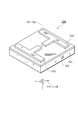
- FIG. 5 is a perspective view of the internal total reflection prism 31 in which the terahertz wave generating element 20, the filter 25, and the terahertz wave detecting element 40 are integrally provided.
- FIG. 4 is a cross-sectional view of the internal total reflection prism 31 in which the terahertz wave generating element 20, the filter 25, and the terahertz wave detecting element 40 are integrally provided.
- FIG. 5 is
- FIG. 6 is a configuration diagram of the total reflection terahertz wave measuring apparatus 2 according to the second embodiment.
- FIG. 7 is a cross-sectional view of the internal total reflection prism 32 in which the terahertz wave generating element 20, the filter 25, and the terahertz wave detecting element 41 are integrally provided.
- FIG. 8 is a perspective view of the photoconductive antenna element.
- FIG. 9 is a configuration diagram of the total reflection terahertz wave measuring apparatus 3 according to the third embodiment.
- FIG. 1 is a configuration diagram of a terahertz wave measuring apparatus 8 according to a first comparative example.
- the terahertz wave measuring device 8 shown in this figure acquires information on the measuring object S by transmission measurement using terahertz waves, and includes a light source 11, a branching unit 12, a chopper 13, and an optical path length difference adjusting unit.
- a polarizer 15 a multiplexing unit 16, a terahertz wave generating element 20, a terahertz wave detecting element 40, a quarter wavelength plate 51, a polarization separating element 52, a photodetector 53a, a photodetector 53b, a differential amplifier 54, and A lock-in amplifier 55 is provided.
- the light source 11 is a femtosecond pulsed laser light source that outputs pulsed light at a constant repetition period and preferably outputs pulsed laser light having a pulse width of about femtoseconds.
- the branching unit 12 is, for example, a beam splitter, splits the pulsed light output from the light source 11 into two, outputs one of the two branched pulsed light to the mirror M1 as pump light, and the other as the probe light to mirror. Output to M4.
- the chopper 13 is provided on the optical path of the pump light between the branch part 12 and the mirror M1, and alternately passes and blocks the pump light at a constant cycle.
- the pump light output from the branching unit 12 and passing through the chopper 13 is sequentially reflected by the mirrors M1 to M3 and input to the terahertz wave generating element 20.
- the optical system of pump light from the branching section 12 to the terahertz wave generating element 20 is hereinafter referred to as “pump optical system”.
- the terahertz wave generating element 20 generates and outputs a pulsed terahertz wave by inputting pump light.
- a nonlinear optical crystal for example, ZnTe
- a photoconductive antenna element for example, an optical switch using GaAs
- It is configured to include either a semiconductor (for example, InAs) or a superconductor.
- the terahertz wave generating element 20 includes a non-linear optical crystal
- the terahertz wave generating element 20 can generate a terahertz wave by a non-linear optical phenomenon that occurs as pump light enters.
- the terahertz wave generating element 20 includes a nonlinear optical crystal.
- the terahertz wave is an electromagnetic wave having a frequency of about 0.01 THz to 100 THz corresponding to an intermediate region between the light wave and the radio wave, and has an intermediate property between the light wave and the radio wave. Further, the pulse terahertz wave is generated at a constant repetition period, and the pulse width is about several picoseconds.
- the terahertz wave output from the terahertz wave generation element 20 acquires information (for example, an absorption coefficient and a refractive index) of the measurement object S by passing through the measurement object S, and then is input to the multiplexing unit 16.
- the terahertz wave optical system from the terahertz wave generating element 20 to the multiplexing unit 16 is hereinafter referred to as a “terahertz wave optical system”.
- the probe light output from the branching unit 12 is sequentially reflected by the mirrors M4 to M8, passes through the polarizer 15, and is input to the multiplexing unit 16.
- the optical system of the probe light from the branching unit 12 to the multiplexing unit 16 is hereinafter referred to as “probe optical system”.
- the four mirrors M4 to M7 constitute an optical path length difference adjusting unit 14. That is, when the mirrors M5 and M6 move, the optical path length between the mirrors M4 and M7 and the mirrors M5 and M6 is adjusted, and the optical path length of the probe optical system is adjusted.
- the optical path length difference adjusting unit 14 includes the optical path of the pump optical system and the terahertz wave optical system from the branching unit 12 to the multiplexing unit 16 and the probe from the branching unit 12 to the multiplexing unit 16. The difference from the optical path of the optical system can be adjusted.
- the multiplexing unit 16 inputs the terahertz wave output from the terahertz wave generation element 20 and transmitted through the measurement object S, and the probe light output from the branching unit 12 and arrived, and the terahertz wave and the probe light are coaxial with each other. Are combined and output to the terahertz wave detecting element 40.
- the combining unit 16 is preferably a pellicle that is a film-like mirror that is bonded to a rigid support frame and stretched thinly.
- the terahertz wave detecting element 40 detects a correlation between the terahertz wave and the probe light.
- the terahertz wave detecting element 40 includes an electro-optic crystal
- the terahertz wave detecting element 40 receives the terahertz wave and the probe light output from the multiplexing unit 16, and birefringence is caused by the Pockels effect as the terahertz wave propagates.
- the probe light is induced and the polarization state of the probe light is changed by the birefringence, and the probe light is output.
- the amount of birefringence at this time depends on the electric field strength of the terahertz wave
- the amount of change in the polarization state of the probe light in the terahertz wave detecting element 40 depends on the electric field strength of the terahertz wave.
- the polarization separation element 52 is, for example, a Wollaston prism, and receives the probe light output from the terahertz wave detection element 40 and passed through the quarter wavelength plate 51, and separates the input probe light into two orthogonal polarization components. And output.
- the photodetectors 53a and 53b include, for example, photodiodes, detect the power of the two polarization components of the probe light polarized and separated by the polarization separation element 52, and difference the electric signal with a value corresponding to the detected power. Output to the dynamic amplifier 54.
- the differential amplifier 54 receives the electric signal output from each of the photodetectors 53a and 53b, and outputs an electric signal having a value corresponding to the difference between the two electric signals to the lock-in amplifier 55.
- the lock-in amplifier 55 synchronously detects the electrical signal output from the differential amplifier 54 at the repetition frequency of passing and blocking the pump light in the chopper 13.
- the signal output from the lock-in amplifier 55 has a value that depends on the electric field strength of the terahertz wave. In this manner, the correlation between the terahertz wave transmitted through the measurement object S and the probe light is detected, and the electric field amplitude of the terahertz wave is detected, so that information on the measurement object S can be obtained.
- This terahertz wave measuring device 8 operates as follows.
- the pulsed light output from the light source 11 is bifurcated by the branching unit 12 to be pump light and probe light.
- the pump light output from the branching unit 12 is sequentially reflected by the mirrors M1 to M3 and input to the terahertz wave generating element 20.
- the terahertz wave generating element 20 generates and outputs a terahertz wave in response to the input of pump light.
- the terahertz wave output from the terahertz wave generating element 20 passes through the measurement object S and is input to the multiplexing unit 16.
- the probe light output from the branching unit 12 is sequentially reflected by the mirrors M4 to M8, converted into linearly polarized light by the polarizer 15, and input to the multiplexing unit 16.
- the terahertz wave and the probe light input to the multiplexing unit 16 are combined by the multiplexing unit 16 so as to be coaxial with each other, and input to the terahertz wave detecting element 40 at substantially the same timing.
- the terahertz wave detecting element 40 to which the terahertz wave and the probe light are input birefringence is induced as the terahertz wave propagates, and the polarization state of the probe light changes due to the birefringence.
- the polarization state of the probe light in the terahertz wave detection element 40 is detected by the quarter wavelength plate 51, the polarization separation element 52, the photodetector 53a, the photodetector 53b, the differential amplifier 54, and the lock-in amplifier 55.
- the in this way a change in the polarization state of the probe light in the terahertz wave detection element 40 is detected, and consequently, the electric field amplitude of the terahertz wave is detected, and the characteristic of the measurement object S is obtained.
- the measurement object S is usually limited to a dry solid.
- the total reflection terahertz wave measuring apparatus 9 according to the second comparative example described below can solve such a problem.
- FIG. 2 is a configuration diagram of the total reflection terahertz wave measuring apparatus 9 according to the second comparative example.
- a total reflection terahertz wave measuring device 9 shown in this figure acquires information on the measuring object S by a total reflection measurement method using a terahertz wave, and includes a light source 11, a branching unit 12, a chopper 13, an optical path length.
- Difference adjustment unit 14 polarizer 15, multiplexing unit 16, terahertz wave generating element 20, prism 30, terahertz wave detecting element 40, quarter wave plate 51, polarization separating element 52, photodetector 53a, photodetector 53b A differential amplifier 54 and a lock-in amplifier 55.
- the total reflection terahertz wave measuring apparatus 9 Compared with the configuration of the terahertz wave measuring apparatus 8 according to the first comparative example shown in FIG. 1, the total reflection terahertz wave measuring apparatus 9 according to the second comparative example shown in FIG. The difference is that a prism 30 is provided.
- the prism 30 inputs the terahertz wave output from the terahertz wave generating element 20 to the incident surface 30a, propagates the input terahertz wave inside, totally reflects the reflected surface 30c, and the terahertz wave after being totally reflected. Is output from the output surface 30 b to the multiplexing unit 16.
- the prism 30 is a duff prism, and the chief ray of the terahertz wave input to the incident surface 30a and the chief ray of the terahertz wave output from the exit surface 30b are on a common straight line.
- the measuring object S is disposed on the reflecting surface 30 c of the prism 30.
- the terahertz wave output from the terahertz wave generating element 20 is input to the incident surface 30 a of the prism 30, propagates through the prism 30 and is totally reflected by the reflecting surface 30 c of the prism 30.
- an evanescent component of the terahertz wave is present in a portion of the measuring object S in the vicinity of the reflecting surface 30c. From this, the terahertz wave after being totally reflected by the reflecting surface 30c of the prism 30 acquires information on a portion of the measuring object S in the vicinity of the reflecting surface 30c.
- the totally reflected terahertz wave propagates inside the prism 30 and is output to the outside from the emission surface 30 b of the prism 30.
- the terahertz wave output from the prism 30 is input to the multiplexing unit 16 together with the probe light that has passed through the probe optical system.
- the terahertz wave and the probe light input to the multiplexing unit 16 are combined by the multiplexing unit 16 so as to be coaxial with each other, and input to the terahertz wave detecting element 40 at substantially the same timing.
- the terahertz wave detecting element 40 to which the terahertz wave and the probe light are input birefringence is induced as the terahertz wave propagates, and the polarization state of the probe light changes due to the birefringence.
- the polarization state of the probe light in the terahertz wave detection element 40 is detected by the quarter wavelength plate 51, the polarization separation element 52, the photodetector 53a, the photodetector 53b, the differential amplifier 54, and the lock-in amplifier 55.
- the in this way a change in the polarization state of the probe light in the terahertz wave detection element 40 is detected, and consequently, the electric field amplitude of the terahertz wave is detected, and the characteristic of the measurement object S is obtained.
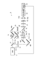
- FIG. 3 is a configuration diagram of the total reflection terahertz wave measuring apparatus 1 according to the first embodiment.
- the total reflection terahertz wave measuring apparatus 1 shown in this figure acquires information on the measuring object S by a total reflection measurement method using terahertz waves, and includes a light source 11, a branching unit 12, a chopper 13, an optical path length.
- Difference adjustment unit 14 polarizer 15, beam splitter 17, terahertz wave generating element 20, filter 25, internal total reflection prism 31, terahertz wave detecting element 40, quarter wavelength plate 51, polarization separating element 52, photodetector 53a , A photodetector 53b, a differential amplifier 54, and a lock-in amplifier 55.
- the total reflection terahertz wave measuring apparatus 1 Compared with the configuration of the total reflection terahertz wave measuring apparatus 9 according to the second comparative example shown in FIG. 2, the total reflection terahertz wave measuring apparatus 1 according to the first embodiment shown in FIG.
- the internal total reflection prism 31 is different in that the terahertz wave generation element 20, the filter 25, and the terahertz wave detection element 40 are provided integrally with the internal total reflection prism 31, The difference is that a beam splitter 17 is provided instead of the multiplexing unit 16.
- the beam splitter 17 may be a pellicle.
- FIG. 4 is a cross-sectional view of the internal total reflection prism 31 in which the terahertz wave generation element 20, the filter 25, and the terahertz wave detection element 40 are integrally provided
- FIG. 5 is a perspective view of the internal total reflection prism 31.
- the internal total reflection prism 31 is a so-called non-aberration prism, and has an entrance surface 31a, an exit surface 31b, a reflection surface 31c, a first sub-reflection surface 31d, and a second sub-reflection surface 31e.
- the entrance surface 31a and the exit surface 31b are parallel to each other.
- the reflecting surface 31c is perpendicular to the entrance surface 31a and the exit surface 31b.
- the terahertz wave generating element 20 and the filter 25 are integrally provided on the incident surface 31 a of the internal total reflection prism 31, and the terahertz wave detecting element 40 is integrally provided on the emission surface 31 b of the internal total reflection prism 31.
- the terahertz wave generating element 20 includes a non-linear optical crystal (for example, ZnTe), and can generate and output a terahertz wave by a non-linear optical phenomenon that appears in the non-linear optical crystal when pump light is incident.
- the chief ray of the terahertz wave output from the terahertz wave generating element 20 and input to the incident surface 31a of the internal total reflection prism 31 is perpendicular to the incident surface 31a, and is output from the output surface 31b of the internal total reflection prism 31 and is supplied to the terahertz.
- the chief ray of the terahertz wave input to the wave detection element 40 is perpendicular to the emission surface 31b, and the chief rays of the input terahertz wave and the output terahertz wave are on a common straight line.
- the internal total reflection prism 31 is made of a material that is transparent at the wavelength of the terahertz wave output from the terahertz wave generating element 20 and has a refractive index higher than the refractive index of the measuring object S disposed on the reflecting surface 31c.
- it is preferably made of silicon. Silicon is transparent in the terahertz wave band, and has a refractive index of 3.4 at a wavelength of 1 THz.
- the refractive index at a wavelength of 1 THz of water is 2.0.
- total reflection occurs when the incident angle is larger than the critical angle.
- total reflection occurs when the measuring object S is a gas.
- the filter 25 is provided between the terahertz wave generating element 20 and the incident surface 31 a of the internal total reflection prism 31.
- the filter 25 transmits the terahertz wave output from the terahertz wave generating element 20 to the internal total reflection prism 31. Further, the filter 25 blocks the pump light transmitted through the terahertz wave generating element 20 and output from the terahertz wave generating element 20.
- the filter 25 preferably includes any one of a reflecting member that reflects pump light, an absorbing member that absorbs pump light, and a scattering member that scatters pump light.
- the filter 25 may be a dielectric multilayer film, for example, a film in which a plurality of SiO 2 films and TiO 2 films each having a predetermined thickness are alternately deposited and stacked. In this case, by appropriately setting the thickness and refractive index of each layer, the pump light can be reflected while transmitting the terahertz wave.
- the filter 25 may be a metal film thinner than the skin depth of the terahertz wave. In this case, the pump 25 can reflect the pump light while transmitting the terahertz wave.
- the filter 25 and the terahertz wave detecting element 40 are integrated with the internal total reflection prism 31, the terahertz wave generation element 20 and the filter 25 are bonded to the incident surface 31 a of the internal total reflection prism 31. Are joined together.
- the filter 25 may be formed by vapor deposition or the like on the terahertz wave emitting surface of the terahertz wave generating element 20 or the incident surface 31a of the internal total reflection prism 31, and then both may be joined by an adhesive.
- the terahertz wave detecting element 40 is bonded to the emission surface 31b of the internal total reflection prism 31 with an adhesive.
- the adhesive used at this time is transparent at the wavelength of the terahertz wave, and is an intermediate between the refractive index of each of the terahertz wave generating element 20 and the terahertz wave detecting element 40 and the refractive index of the internal total reflection prism 31 or It is preferable to have an equivalent refractive index.
- the filter 25 may also serve as a bonding agent used when the terahertz wave generating element 20 and the internal total reflection prism 31 are bonded.
- a specific example of the filter 25 in this case is as follows.
- the filter 25 is a double-sided tape made of, for example, PTFE (polytetrafluoroethylene) that is transparent to terahertz waves and opaque to pump light.
- the generating element 20 and the internal total reflection prism 31 may be joined. In this case, the pump light can be absorbed while the terahertz wave is transmitted by the double-sided tape.
- the filter 25 is a mixture of a colorant that is transparent to terahertz waves and opaque to pump light, mixed with wax or an epoxy or acrylic adhesive.
- the terahertz wave generating element 20 and the internal total reflection prism 31 may be bonded with an adhesive.
- the pump light can be absorbed while the terahertz wave is transmitted by the colorant contained in the adhesive.
- the filter 25 may apply an adhesive on both sides of a black polyethylene film, thereby joining the terahertz wave generating element 20 and the internal total reflection prism 31.
- the pump light can be absorbed while the terahertz wave is transmitted by the black polyethylene film.
- the filter 25 is obtained by mixing fine particles having a particle size of several ⁇ m or less in an adhesive, and the terahertz wave generating element 20 and the internal total reflection prism 31 are bonded by this adhesive. May be.
- the pump light can be scattered while the terahertz wave is transmitted by the fine particles contained in the adhesive.
- the reflectivity is high at the wavelength of the probe light at the joint position between the reflection surface 31 b of the internal total reflection prism 31 and the terahertz wave detection element 40.
- a dielectric multilayer film may be formed on the reflection surface 31b, and thus, it may be transparent to the terahertz wave and have a high reflectance to the probe light.
- the internal total reflection prism 31 immediately inputs the terahertz wave output from the terahertz wave generation element 20 and transmitted through the filter 25 to the incident surface 31a, propagates the input terahertz wave inside, and is transmitted by the first sub-reflection surface 31d. The light is reflected and incident on the reflection surface 31c. Further, the internal total reflection prism 31 totally reflects the terahertz wave incident on the reflection surface 31c by the reflection surface 31c, propagates the subsequent terahertz wave inside and reflects it by the second sub-reflection surface 31e, and outputs it. The signal is output from 31b and immediately input to the terahertz wave detecting element 40.
- This total reflection terahertz wave measuring apparatus 1 operates as follows.
- the pulsed light output from the light source 11 is bifurcated by the branching unit 12 to be pump light and probe light.
- the pump light output from the branching unit 12 is sequentially reflected by the mirrors M1 to M3 and input to the terahertz wave generating element 20 provided integrally with the incident surface 31a of the internal total reflection prism 31.
- the terahertz wave generating element 20 generates and outputs a terahertz wave in response to the input of pump light.
- the terahertz wave output from the terahertz wave generating element 20 passes through the filter 25 without being propagated in space, is immediately input to the incident surface 31a of the internal total reflection prism 31, and propagates through the internal total reflection prism 31.
- the light is reflected by the first sub-reflection surface 31d, enters the reflection surface 31c, and is totally reflected by the reflection surface 31c.
- the pump light input to the terahertz wave generating element 20 including the nonlinear optical crystal may pass through the terahertz wave generating element 20, but the transmitted pump light is blocked by the filter 25. Accordingly, the pump light is suppressed from being input to the internal total reflection prism 31.
- the evanescent component of the terahertz wave is present in the portion of the measurement object S arranged on the reflection surface 31c in the vicinity of the reflection surface 31c. From this, the terahertz wave after being totally reflected by the reflection surface 31c of the internal total reflection prism 31 acquires information on a portion of the measurement object S that is in the vicinity of the reflection surface 31c. Then, the totally reflected terahertz wave is reflected by the second sub-reflecting surface 31e of the internal total reflection prism 31 and output from the output surface 31b, and immediately, without being propagated in space, the output surface 31b of the internal total reflection prism 31.
- a terahertz wave detecting element 40 provided integrally therewith.
- the probe light output from the branching unit 12 is sequentially reflected by the mirrors M4 to M8 and the beam splitter 17 and input to the terahertz wave detecting element 40.
- the probe light input from the beam splitter 17 to the terahertz wave detection element 40 passes through the terahertz wave detection element 40, is reflected by the emission surface 31b of the internal total reflection prism 31, and passes through the terahertz wave detection element 40 again. It is output to the beam splitter 17.
- the terahertz wave and the probe light are input to the terahertz wave detecting element 40 at substantially the same timing so as to be coaxial with each other.
- the terahertz wave detecting element 40 to which the terahertz wave and the probe light are input birefringence is induced as the terahertz wave propagates, and the polarization state of the probe light changes due to the birefringence.
- the probe light output from the terahertz wave detection element 40 to the beam splitter 17 passes through the beam splitter 17.
- the polarization state of the probe light is detected by the quarter wavelength plate 51, the polarization separation element 52, the photodetector 53a, the photodetector 53b, the differential amplifier 54, and the lock-in amplifier 55. In this way, a change in the polarization state of the probe light in the terahertz wave detection element 40 is detected, and consequently, the electric field amplitude of the terahertz wave is detected, and the characteristic of the measurement
- the optical path length difference adjusting unit 14 adjusts the optical path length between the mirrors M4 and M7 and the mirrors M5 and M6, and adjusts the optical path length of the probe optical system, so that it is input to the terahertz wave detection element 40.
- the timing difference between the terahertz wave and the probe light is adjusted.
- the pulse width of the terahertz wave is generally about picoseconds, whereas the pulse width of the probe light is about femtoseconds, and the pulse width of the probe light is several orders of magnitude narrower than that of the terahertz wave. From this, the time waveform of the electric field amplitude of the pulsed terahertz wave is obtained by sweeping the incident timing of the probe light to the terahertz wave detecting element 40 by the optical path length difference adjusting unit 14.
- the total reflection terahertz wave measuring apparatus 1 uses the information about the measurement object S arranged on the reflection surface 31c of the internal total reflection prism 31 as the total reflection of the terahertz wave. Acquired by the evanescent component of the terahertz wave generated at the time. From this, even if the measuring object S contains moisture, it can be measured easily and with high sensitivity. Further, since the terahertz wave generating element 20, the filter 25, and the terahertz wave detecting element 40 are provided integrally with the internal total reflection prism 31, they are easy to handle, and this point can be easily measured. It is possible to reduce the size.
- the terahertz wave propagates through the internal total reflection prism 31 without spatial propagation from the terahertz wave generating element 20 to the terahertz wave detecting element 40, it is not necessary to perform nitrogen purge, and this point can be easily measured. In addition, miniaturization is possible. Furthermore, since the loss of terahertz waves on the entrance surface 31a and the exit surface 31b of the internal total reflection prism 31 is reduced, it is possible to measure with high sensitivity also in this respect.
- a filter 25 is provided between the terahertz wave generating element 20 and the incident surface 31a of the internal total reflection prism 31, and the terahertz wave is transmitted by the filter 25. Then, the pump light is blocked while being input to the internal total reflection prism 31. Accordingly, the pump light is suppressed from being input to the internal total reflection prism 31.
- the internal total reflection prism 31 is made of a semiconductor such as silicon, if pump light having photon energy higher than the band gap energy of the semiconductor propagates through the internal total reflection prism 31, the internal total reflection prism 31 is free. Carriers are generated, and as a result, the terahertz wave propagating through the internal total reflection prism 31 is absorbed, and the intensity of the terahertz wave reaching the terahertz wave detecting element 40 is reduced.
- pump light entering the internal total reflection prism 31 by the filter 25 provided between the terahertz wave generating element 20 and the incident surface 31a of the internal total reflection prism 31 is used. Is suppressed, and the absorption of the terahertz wave propagating through the internal total reflection prism 31 is suppressed.
- FIG. 6 is a configuration diagram of the total reflection terahertz wave measuring apparatus 2 according to the second embodiment.
- the total reflection terahertz wave measuring apparatus 2 shown in this figure acquires information on the measuring object S by a total reflection measurement method using terahertz waves, and includes a light source 11, a branching unit 12, a chopper 13, an optical path length.
- a difference adjustment unit 14, a terahertz wave generation element 20, a filter 25, an internal total reflection prism 32, a terahertz wave detection element 41, and a synchronization detection unit 57 are provided.
- FIG. 7 is a cross-sectional view of the internal total reflection prism 32 in which the terahertz wave generating element 20, the filter 25, and the terahertz wave detecting element 41 are integrally provided.
- the internal total reflection prism 32 is a so-called non-aberration prism, and has an entrance surface 32a, an exit surface 32b, a reflection surface 32c, a first sub-reflection surface 32d, and a second sub-reflection surface 32e.
- the entrance surface 32a and the exit surface 32b are parallel to each other.
- the reflection surface 32c is perpendicular to the entrance surface 32a and the exit surface 32b.
- the terahertz wave generating element 20 and the filter 25 are integrally provided on the incident surface 32 a of the internal total reflection prism 32, and the terahertz wave detecting element 41 is integrally provided on the emission surface 32 b of the internal total reflection prism 32.
- a photoconductive antenna element as shown in FIG. 8 is used as the terahertz wave detecting element 41.
- a photoconductive antenna element 100 shown in FIG. 8 is used as a terahertz wave detecting element 41.
- a semi-insulating GaAs substrate 101, a GaAs layer 102 formed on the GaAs substrate 101, and A pair of electrodes 103 and 104 are formed on the GaAs layer 102.
- the GaAs layer 102 is epitaxially grown by MBE at a low temperature (for example, 200 to 250 ° C.), and has a thickness of 1 to 3 ⁇ m, for example.
- the electrode 103 and the electrode 104 are ohmic electrodes such as AuGe / Au, the length of the antenna is, for example, 20 ⁇ m to 2 mm, and the distance between them is, for example, 3 to 10 ⁇ m.
- the GaAs layer 102 formed by low temperature epitaxial growth has a short carrier lifetime, high carrier mobility, and high impedance.
- a current representing the correlation between the electrodes 103 and 104 is generated according to the incidence of the terahertz wave and the probe light. Based on this correlation, the spectrum of the terahertz wave can be obtained, and information on the measurement object can be obtained.
- the current generated between the electrode 103 and the electrode 104 of the photoconductive antenna element 100 serving as the terahertz wave detecting element 41 is generated by the synchronization detection unit 57 by the period of terahertz wave generation in the terahertz wave generating element 20 (that is, pumped by the chopper 13). It is detected in synchronization with the light passage period).
- a nonlinear optical crystal as the terahertz wave generating element 20 and the filter 25 are integrally provided on the incident surface 32 a of the internal total reflection prism 32, and the output surface 32 b of the internal total reflection prism 32.
- the terahertz wave detecting element 41 is integrally provided with the photoconductive antenna element as described above. Therefore, it is necessary to make the terahertz wave incident between the electrode 103 and the electrode 104 of the photoconductive antenna element as the terahertz wave detecting element 41.
- an optical element that has a condensing effect on the terahertz wave propagating through the internal total reflection prism 32 is formed on the exit surface 32 b side of the internal total reflection prism 32. That is, the second sub-reflection surface 32e has a shape of an off-axis parabolic mirror. Thereby, the terahertz wave totally reflected by the reflecting surface 32c is reflected by the off-axis parabolic mirror of the second sub-reflecting surface 32e, and photoconductive as the terahertz wave detecting element 41 provided on the emitting surface 32b. The light is collected and incident between the electrode 103 and the electrode 104 of the antenna element.
- This total reflection terahertz wave measuring apparatus 2 operates as follows.
- the pulsed light output from the light source 11 is bifurcated by the branching unit 12 to be pump light and probe light.
- the pump light output from the branching unit 12 is sequentially reflected by the mirrors M1 to M3, and input to the terahertz wave generating element 20 provided integrally with the incident surface 32a of the internal total reflection prism 32.
- the terahertz wave generating element 20 generates and outputs a terahertz wave in response to the input of pump light.
- the terahertz wave output from the terahertz wave generating element 20 passes through the filter 25 without being propagated in space, is immediately input to the incident surface 32a of the internal total reflection prism 32, and propagates through the internal total reflection prism 32.
- the light is reflected by the first sub-reflecting surface 32d, enters the reflecting surface 32c, and is totally reflected by the reflecting surface 32c.
- the pump light input to the terahertz wave generating element 20 including the nonlinear optical crystal may pass through the terahertz wave generating element 20, but the transmitted pump light is blocked by the filter 25. Therefore, the pump light is prevented from being input to the internal total reflection prism 32.
- the evanescent component of the terahertz wave is present in a portion of the measuring object S arranged on the reflecting surface 32c in the vicinity of the reflecting surface 32c. From this, the terahertz wave after being totally reflected by the reflection surface 32c of the internal total reflection prism 32 acquires information on a portion of the measuring object S in the vicinity of the reflection surface 32c. Then, the totally reflected terahertz wave is reflected by the off-axis parabolic mirror of the second sub-reflecting surface 32e, is output from the exit surface 32b of the internal total reflection prism 32, and is immediately transmitted without being propagated in space. The light is input to a terahertz wave detection element 41 provided integrally with the emission surface 32 b of the total reflection prism 32.
- the probe light output from the branching section 12 and sequentially reflected by the mirrors M4 to M9 is input between the electrode 103 and the electrode 104 of the photoconductive antenna element 100 as the terahertz wave detecting element 41.
- the terahertz wave output from the emission surface 32 b of the internal total reflection prism 32 is also input between the electrode 103 and the electrode 104 of the photoconductive antenna element 100 as the terahertz wave detection element 41.
- the probe light input to the terahertz wave detection element 41 is not input into the internal total reflection prism 32 because it is absorbed by the semiconductor material (GaAs) constituting the terahertz wave detection element 41.
- terahertz waves are also generated intermittently at a constant cycle.
- a current representing the correlation between the electrodes 103 and 104 is generated in response to the incidence of the terahertz wave and the probe light.
- This current is detected by the synchronization detection unit 57 in synchronization with the pump light passing period in the chopper 13. As a result, the spectrum of the terahertz wave is obtained, and information on the measurement object S is obtained.
- the total reflection terahertz wave measuring apparatus 2 according to the second embodiment can exhibit the same effect as the effect of the total reflection terahertz wave measuring apparatus 1 according to the first embodiment.
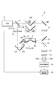
- FIG. 9 is a configuration diagram of the total reflection terahertz wave measuring apparatus 3 according to the third embodiment.
- the total reflection terahertz wave measuring apparatus 3 shown in this figure acquires information on the measuring object S by a total reflection measurement method using terahertz waves, and includes a light source 11, a branching unit 12, a chopper 13, an optical path length.
- Difference adjustment unit 14 polarizer 15, mirrors 18 and 19, terahertz wave generating element 20, filter 25, total internal reflection prism 31, terahertz wave detecting element 40, quarter wavelength plate 51, polarization separating element 52, photodetector 53a, a photodetector 53b, a differential amplifier 54, and a lock-in amplifier 55.
- the total reflection terahertz wave measuring apparatus 3 Compared to the configuration of the total reflection terahertz wave measuring apparatus 1 according to the first embodiment shown in FIG. 3, the total reflection terahertz wave measuring apparatus 3 according to the third embodiment shown in FIG. It is different in that mirrors 18 and 19 are provided instead. Along with this, the arrangement of the quarter wavelength plate 51, the polarization separation element 52, the photodetector 53a, the photodetector 53b, and the like is also changed in accordance with the optical path.
- This total reflection terahertz wave measuring apparatus 3 operates as follows.
- the pulsed light output from the light source 11 is bifurcated by the branching unit 12 to be pump light and probe light.
- the pump light output from the branching unit 12 is sequentially reflected by the mirrors M1 to M3 and input to the terahertz wave generating element 20 provided integrally with the incident surface 31a of the internal total reflection prism 31.
- the terahertz wave generating element 20 generates and outputs a terahertz wave in response to the input of pump light.
- the terahertz wave output from the terahertz wave generating element 20 passes through the filter 25 without being propagated in space, is immediately input to the incident surface 31a of the internal total reflection prism 31, and propagates through the internal total reflection prism 31.
- the light is reflected by the first sub-reflection surface 31d, enters the reflection surface 31c, and is totally reflected by the reflection surface 31c.
- the pump light input to the terahertz wave generating element 20 including the nonlinear optical crystal may pass through the terahertz wave generating element 20, but the transmitted pump light is blocked by the filter 25. Accordingly, the pump light is suppressed from being input to the internal total reflection prism 31.
- the evanescent component of the terahertz wave is present in the portion of the measurement object S arranged on the reflection surface 31c in the vicinity of the reflection surface 31c. From this, the terahertz wave after being totally reflected by the reflection surface 31c of the internal total reflection prism 31 acquires information on a portion of the measurement object S that is in the vicinity of the reflection surface 31c. Then, the totally reflected terahertz wave is reflected by the second sub-reflecting surface 31e of the internal total reflection prism 31 and output from the output surface 31b, and immediately, without being propagated in space, the output surface 31b of the internal total reflection prism 31.
- a terahertz wave detecting element 40 provided integrally therewith.
- the probe light output from the branching unit 12 is sequentially reflected by the mirrors M4 to M8 and the mirror 18 and input to the terahertz wave detecting element 40.
- the probe light input from the mirror 18 to the terahertz wave detection element 40 passes through the terahertz wave detection element 40, is reflected by the emission surface 31 b of the internal total reflection prism 31, passes through the terahertz wave detection element 40 again, and is mirrored. 19 is output.
- the terahertz wave and the probe light are input to the terahertz wave detecting element 40 at substantially the same timing.
- the terahertz wave detecting element 40 to which the terahertz wave and the probe light are input birefringence is induced as the terahertz wave propagates, and the polarization state of the probe light changes due to the birefringence.
- the probe light output from the terahertz wave detection element 40 to the mirror 19 is reflected by the mirror 19.
- the polarization state of the probe light is detected by the quarter wavelength plate 51, the polarization separation element 52, the photodetector 53a, the photodetector 53b, the differential amplifier 54, and the lock-in amplifier 55. In this way, a change in the polarization state of the probe light in the terahertz wave detection element 40 is detected, and consequently, the electric field amplitude of the terahertz wave is detected, and the characteristic of the measurement object S is obtained.
- the total reflection terahertz wave measuring apparatus 3 according to the third embodiment can achieve the same effects as the total reflection terahertz wave measuring apparatus 1 according to the first embodiment.
- mirrors 18 and 19 with preferably 100% reflectivity are used instead of the beam splitter 17. For this reason, it is possible to suppress a decrease in probe light power due to light reflection and transmission at the beam splitter.
- the optical path of the probe light is inclined to some extent with respect to the terahertz wave detection element 40. For this reason, although the terahertz wave and the probe light are not perfectly coaxial, in the terahertz wave detecting element 40, a change in the polarization state of the probe light that is almost the same as that when the terahertz wave is made coaxial can be obtained. The impact of is small.
- the total reflection terahertz wave measuring apparatus includes (1) a light source that outputs light, and (2) two branches of light output from the light source, and pumps one of the two branched lights.
- Total internal reflection that inputs the terahertz wave output from the terahertz wave generating element to the incident surface propagates the input terahertz wave internally and totally reflects it on the reflecting surface, and outputs the terahertz wave from the emitting surface to the outside
- the terahertz wave output from the terahertz wave generating element is provided between the prism and (5) the incident surface of the terahertz wave generating element and the internal total reflection prism.
- a filter that blocks the pump light transmitted from the terahertz wave generation element through the terahertz wave generation element, and (6) the terahertz wave output from the exit surface of the internal total reflection prism and the output from the branching unit
- a configuration including a terahertz wave detection element that inputs the probe light thus detected and detects a correlation between the terahertz wave and the probe light is used.
- the terahertz wave generating element and the filter are integrally provided on the incident surface of the internal total reflection prism, and the terahertz wave detecting element is integrally provided on the emission surface of the internal total reflection prism.
- a configuration is used in which information about the measurement object disposed on the reflection surface of the internal total reflection prism is acquired by an evanescent component of the terahertz wave generated during total reflection of the terahertz wave.
- the filter includes any one of a reflecting member that reflects pump light, an absorbing member that absorbs pump light, and a scattering member that scatters pump light.
- the measuring apparatus also adjusts the difference between the optical path of the pump light and the terahertz wave from the branching section to the terahertz wave detecting element and the optical path of the probe light from the branching section to the terahertz wave detecting element. It is preferable to further include an optical path length difference adjusting unit.
- the optical path length difference adjustment unit adjusts the timing at which each of the terahertz wave and the probe light is input to the terahertz wave detection element, and the timing is swept so that the electric field amplitude of the pulse terahertz wave is adjusted. A time waveform is obtained.
- the optical path length difference adjusting unit may be provided in any optical system of pump light, probe light, and terahertz wave.
- an optical element that has a condensing function with respect to the terahertz wave propagating through the internal total reflection prism is formed on the exit surface side of the internal total reflection prism.
- the terahertz wave detecting element is a photoconductive antenna element. Is convenient in some cases.
- the internal total reflection prism is reflected by the reflection surface and the first sub-reflection surface that reflects the terahertz wave that is input to the incident surface and propagates inside the reflection surface, in addition to the incident surface, the reflective surface, and the output surface. It is preferable to have a second sub-reflection surface that reflects the terahertz wave propagating through the inside to the emission surface. Further, the chief ray of the terahertz wave input to the incident surface of the internal total reflection prism and the chief ray of the terahertz wave output from the exit surface of the internal total reflection prism are preferably on a common straight line. .
- Such an internal total reflection prism is realized by, for example, a non-aberration prism.
- the present invention can be used as a total reflection terahertz wave measuring apparatus that can be miniaturized.
Landscapes
- Physics & Mathematics (AREA)
- Spectroscopy & Molecular Physics (AREA)
- Health & Medical Sciences (AREA)
- General Physics & Mathematics (AREA)
- Life Sciences & Earth Sciences (AREA)
- Chemical & Material Sciences (AREA)
- Analytical Chemistry (AREA)
- Biochemistry (AREA)
- General Health & Medical Sciences (AREA)
- Immunology (AREA)
- Pathology (AREA)
- Toxicology (AREA)
- Investigating Or Analysing Materials By Optical Means (AREA)
Abstract
Priority Applications (4)
| Application Number | Priority Date | Filing Date | Title |
|---|---|---|---|
| CN2009801156885A CN102016548B (zh) | 2008-04-30 | 2009-04-27 | 全反射太赫兹波测定装置 |
| EP09738790.6A EP2273254A4 (fr) | 2008-04-30 | 2009-04-27 | Dispositif de mesure d'ondes térahertziennes de réflexion totale |
| US12/988,158 US8415625B2 (en) | 2008-04-30 | 2009-04-27 | Total reflection terahertz wave measurement device |
| JP2010510120A JP5231538B2 (ja) | 2008-04-30 | 2009-04-27 | 全反射テラヘルツ波測定装置 |
Applications Claiming Priority (2)
| Application Number | Priority Date | Filing Date | Title |
|---|---|---|---|
| JP2008118864 | 2008-04-30 | ||
| JP2008-118864 | 2008-04-30 |
Publications (1)
| Publication Number | Publication Date |
|---|---|
| WO2009133853A1 true WO2009133853A1 (fr) | 2009-11-05 |
Family
ID=41255069
Family Applications (1)
| Application Number | Title | Priority Date | Filing Date |
|---|---|---|---|
| PCT/JP2009/058282 WO2009133853A1 (fr) | 2008-04-30 | 2009-04-27 | Dispositif de mesure d'ondes térahertziennes de réflexion totale |
Country Status (5)
| Country | Link |
|---|---|
| US (1) | US8415625B2 (fr) |
| EP (1) | EP2273254A4 (fr) |
| JP (1) | JP5231538B2 (fr) |
| CN (1) | CN102016548B (fr) |
| WO (1) | WO2009133853A1 (fr) |
Cited By (4)
| Publication number | Priority date | Publication date | Assignee | Title |
|---|---|---|---|---|
| JP2014119448A (ja) * | 2012-12-17 | 2014-06-30 | Advantest Corp | 光線入射装置および反射光測定装置 |
| JP2017207446A (ja) * | 2016-05-20 | 2017-11-24 | 浜松ホトニクス株式会社 | 全反射分光計測装置及び全反射分光計測方法 |
| JP2019132595A (ja) * | 2018-01-29 | 2019-08-08 | 浜松ホトニクス株式会社 | テラヘルツ波分光計測装置 |
| WO2020213350A1 (fr) * | 2019-04-15 | 2020-10-22 | 横河電機株式会社 | Dispositif et procédé de mesure |
Families Citing this family (26)
| Publication number | Priority date | Publication date | Assignee | Title |
|---|---|---|---|---|
| JP5566826B2 (ja) * | 2010-09-15 | 2014-08-06 | 浜松ホトニクス株式会社 | 全反射分光計測におけるデータ解析方法 |
| EP2693199B1 (fr) * | 2011-03-29 | 2018-07-11 | Hamamatsu Photonics K.K. | Spectromètre à ondes térahertz et élément de prisme |
| WO2012132647A1 (fr) | 2011-03-29 | 2012-10-04 | 浜松ホトニクス株式会社 | Spectromètre à ondes térahertz |
| DE102011112893A1 (de) * | 2011-09-06 | 2013-03-07 | Philipp Kubina | Verfahren und Vorrichtung zur zeitaufgelösten Messung von Messsignalen |
| CN102590125A (zh) * | 2011-11-30 | 2012-07-18 | 天津大学 | 基于太赫兹波atr成像生物组织水分测量装置及方法 |
| JP5848621B2 (ja) * | 2012-01-25 | 2016-01-27 | 浜松ホトニクス株式会社 | 薬物評価方法及び薬物評価装置 |
| US20130222787A1 (en) * | 2012-02-23 | 2013-08-29 | Canon Kabushiki Kaisha | Roughness evaluating apparatus, and object evaluating apparatus and roughness evaluating method using the same |
| CN102620666A (zh) * | 2012-03-29 | 2012-08-01 | 吴周令 | 一种半导体晶圆厚度检测系统及其检测方法 |
| CN103792657A (zh) * | 2012-10-30 | 2014-05-14 | 福州高意通讯有限公司 | 一种光程微调结构及其应用结构 |
| JP2014163674A (ja) * | 2013-02-21 | 2014-09-08 | Seiko Epson Corp | テラヘルツ波検出装置、カメラ、イメージング装置、および計測装置 |
| JP6391921B2 (ja) | 2013-07-30 | 2018-09-19 | 浜松ホトニクス株式会社 | 波長板及び分割プリズム部材 |
| CN103715478B (zh) * | 2013-12-26 | 2016-03-02 | 合肥知常光电科技有限公司 | 一种可调谐的太赫兹波滤波装置及其滤波方法 |
| JP6294696B2 (ja) | 2014-02-14 | 2018-03-14 | 株式会社日立ハイテクノロジーズ | 遠赤外撮像装置、および遠赤外撮像方法 |
| JP6096725B2 (ja) * | 2014-09-09 | 2017-03-15 | アイシン精機株式会社 | 膜厚測定装置及び膜厚測定方法 |
| CN105548083A (zh) * | 2015-12-08 | 2016-05-04 | 电子科技大学 | 双光路太赫兹时域光谱仪 |
| CN105572052B (zh) * | 2015-12-17 | 2018-09-07 | 哈尔滨工业大学 | 一种紧凑型连续太赫兹双轴共焦扫描反射式偏振成像装置及成像方法 |
| CN105928898A (zh) * | 2016-04-15 | 2016-09-07 | 中国人民解放军第三军医大学第附属医院 | 一种基于道威棱镜快速搭建的太赫兹衰减全反射系统 |
| CN106248616B (zh) * | 2016-09-27 | 2017-10-24 | 深圳市太赫兹科技创新研究院有限公司 | 太赫兹全偏振态检测光谱仪 |
| US10508985B2 (en) * | 2017-06-05 | 2019-12-17 | Northwestern University | Systems and methods for pump-probe spectroscopy |
| CN107782694B (zh) * | 2017-09-28 | 2020-02-21 | 上海无线电设备研究所 | 太赫兹时域光谱全极化电磁散射测量系统及获取方法 |
| CN108107008B (zh) * | 2017-12-11 | 2021-02-23 | 南京大学 | 一种时域热反射谱测量系统 |
| CN108195792B (zh) * | 2017-12-25 | 2023-07-28 | 中国科学院紫金山天文台 | 一种基于超导探测器的太赫兹波段大气发射谱线测量装置 |
| CN108267421A (zh) * | 2017-12-30 | 2018-07-10 | 深圳市太赫兹科技创新研究院有限公司 | 一种奶粉中三聚氰胺的检测方法及检测系统 |
| JP6955462B2 (ja) * | 2018-03-02 | 2021-10-27 | 浜松ホトニクス株式会社 | 光学計測装置及び光学計測方法 |
| GB2583071B (en) * | 2019-03-22 | 2021-12-08 | Biocel Instruments Ltd | Attenuated total reflection spectrometer |
| CN114166791B (zh) * | 2021-08-12 | 2024-03-19 | 博微太赫兹信息科技有限公司 | 生物医学成像用太赫兹时域光谱探头装置及时域光谱仪 |
Citations (4)
| Publication number | Priority date | Publication date | Assignee | Title |
|---|---|---|---|---|
| JP2004219967A (ja) * | 2003-01-13 | 2004-08-05 | Tetsuo Yanai | テラヘルツ波発生装置及び計測装置 |
| JP2004354246A (ja) | 2003-05-29 | 2004-12-16 | Aisin Seiki Co Ltd | 反射型テラヘルツ分光測定装置及び測定方法 |
| JP2006184078A (ja) | 2004-12-27 | 2006-07-13 | Canon Inc | 被対象物を透過した電磁波の状態を検出するための検出装置 |
| JP2008224449A (ja) * | 2007-03-13 | 2008-09-25 | Hamamatsu Photonics Kk | 全反射テラヘルツ波測定装置 |
Family Cites Families (9)
| Publication number | Priority date | Publication date | Assignee | Title |
|---|---|---|---|---|
| US6166866A (en) * | 1995-02-28 | 2000-12-26 | Canon Kabushiki Kaisha | Reflecting type optical system |
| GB2352512B (en) * | 1999-07-23 | 2002-03-13 | Toshiba Res Europ Ltd | A radiation probe and detecting tooth decay |
| GB2371618B (en) * | 2001-01-30 | 2004-11-17 | Teraprobe Ltd | A probe, apparatus and method for examining a sample |
| JP4280654B2 (ja) * | 2004-02-17 | 2009-06-17 | アイシン精機株式会社 | マルチチャンネルテラヘルツ波スペクトル測定法及び測定装置 |
| JP4546326B2 (ja) * | 2004-07-30 | 2010-09-15 | キヤノン株式会社 | センシング装置 |
| GB0601967D0 (en) * | 2006-02-01 | 2006-03-15 | Univ St Andrews | Device and method for optimising output coupling of EM radiation |
| CN2874476Y (zh) | 2006-02-10 | 2007-02-28 | 天津大学 | 基于光学整流的太赫兹时域光谱仪 |
| JP4790560B2 (ja) * | 2006-10-10 | 2011-10-12 | 浜松ホトニクス株式会社 | 単発テラヘルツ波時間波形計測装置 |
| JP5035618B2 (ja) * | 2006-12-05 | 2012-09-26 | 独立行政法人理化学研究所 | 電磁波を用いた検出方法、及び検出装置 |
-
2009
- 2009-04-27 CN CN2009801156885A patent/CN102016548B/zh active Active
- 2009-04-27 US US12/988,158 patent/US8415625B2/en active Active
- 2009-04-27 JP JP2010510120A patent/JP5231538B2/ja active Active
- 2009-04-27 EP EP09738790.6A patent/EP2273254A4/fr not_active Withdrawn
- 2009-04-27 WO PCT/JP2009/058282 patent/WO2009133853A1/fr active Application Filing
Patent Citations (4)
| Publication number | Priority date | Publication date | Assignee | Title |
|---|---|---|---|---|
| JP2004219967A (ja) * | 2003-01-13 | 2004-08-05 | Tetsuo Yanai | テラヘルツ波発生装置及び計測装置 |
| JP2004354246A (ja) | 2003-05-29 | 2004-12-16 | Aisin Seiki Co Ltd | 反射型テラヘルツ分光測定装置及び測定方法 |
| JP2006184078A (ja) | 2004-12-27 | 2006-07-13 | Canon Inc | 被対象物を透過した電磁波の状態を検出するための検出装置 |
| JP2008224449A (ja) * | 2007-03-13 | 2008-09-25 | Hamamatsu Photonics Kk | 全反射テラヘルツ波測定装置 |
Non-Patent Citations (2)
| Title |
|---|
| H. HIRORI ET AL.: "Destructive interference effect on surface plasmon resonance in terahertz attenuated total reflection", OPTICS EXPRESS, vol. 13, no. 26, 26 December 2005 (2005-12-26), pages 10801 - 10814, XP008118065 * |
| See also references of EP2273254A4 |
Cited By (11)
| Publication number | Priority date | Publication date | Assignee | Title |
|---|---|---|---|---|
| JP2014119448A (ja) * | 2012-12-17 | 2014-06-30 | Advantest Corp | 光線入射装置および反射光測定装置 |
| JP2017207446A (ja) * | 2016-05-20 | 2017-11-24 | 浜松ホトニクス株式会社 | 全反射分光計測装置及び全反射分光計測方法 |
| JP2019132595A (ja) * | 2018-01-29 | 2019-08-08 | 浜松ホトニクス株式会社 | テラヘルツ波分光計測装置 |
| US10697891B2 (en) | 2018-01-29 | 2020-06-30 | Hamamatsu Photonics K.K. | Terahertz wave spectroscopic measurement device |
| JP2021175986A (ja) * | 2018-01-29 | 2021-11-04 | 浜松ホトニクス株式会社 | テラヘルツ波分光計測装置 |
| JP7014623B2 (ja) | 2018-01-29 | 2022-02-01 | 浜松ホトニクス株式会社 | テラヘルツ波分光計測装置 |
| JP7393397B2 (ja) | 2018-01-29 | 2023-12-06 | 浜松ホトニクス株式会社 | テラヘルツ波分光計測装置 |
| WO2020213350A1 (fr) * | 2019-04-15 | 2020-10-22 | 横河電機株式会社 | Dispositif et procédé de mesure |
| JP2020176848A (ja) * | 2019-04-15 | 2020-10-29 | 横河電機株式会社 | 測定装置及び測定方法 |
| JP7095648B2 (ja) | 2019-04-15 | 2022-07-05 | 横河電機株式会社 | 測定装置及び測定方法 |
| US11933726B2 (en) | 2019-04-15 | 2024-03-19 | Yokogawa Electric Corporation | Measurement apparatus and measurement method |
Also Published As
| Publication number | Publication date |
|---|---|
| CN102016548B (zh) | 2012-09-05 |
| EP2273254A1 (fr) | 2011-01-12 |
| JP5231538B2 (ja) | 2013-07-10 |
| JPWO2009133853A1 (ja) | 2011-09-01 |
| EP2273254A4 (fr) | 2014-02-26 |
| US8415625B2 (en) | 2013-04-09 |
| US20110249253A1 (en) | 2011-10-13 |
| CN102016548A (zh) | 2011-04-13 |
Similar Documents
| Publication | Publication Date | Title |
|---|---|---|
| JP5231538B2 (ja) | 全反射テラヘルツ波測定装置 | |
| JP4871176B2 (ja) | 全反射テラヘルツ波測定装置 | |
| JP4800244B2 (ja) | テラヘルツ波測定装置 | |
| JP3950818B2 (ja) | 反射型テラヘルツ分光測定装置及び測定方法 | |
| US5952818A (en) | Electro-optical sensing apparatus and method for characterizing free-space electromagnetic radiation | |
| US8742353B2 (en) | Single terahertz wave time-waveform measuring device | |
| JP2008224452A (ja) | 全反射テラヘルツ波測定装置 | |
| JP6238058B2 (ja) | テラヘルツ分光システム | |
| US8759769B2 (en) | Terahertz-wave device, method of generating and detecting terahertz-waves with the device, and imaging apparatus equipped with the device | |
| US8759779B2 (en) | Terahertz wave generation element, terahertz wave detection element, and terahertz time domain spectral device | |
| JP5836683B2 (ja) | 電磁波発生素子、電磁波検出素子、時間領域分光装置 | |
| US9696206B2 (en) | Terahertz-wave spectrometer | |
| US10895504B2 (en) | Terahertz wave spectroscopic measurement apparatus and terahertz wave spectroscopic measurement method | |
| JP7393397B2 (ja) | テラヘルツ波分光計測装置 | |
| US9080913B2 (en) | Terahertz-wave spectrometer and prism member | |
| CN208026605U (zh) | 一种小型化的太赫兹时域光谱仪装置 | |
| CN108680500A (zh) | 一种小型化的太赫兹时域光谱仪装置及分析方法 | |
| US20040262544A1 (en) | Semiconductor surface-field emitter for T-ray generation | |
| Hatem | Optimizing the electro-optic detection of terahertz waves by ZnTe at 780 and 1560-nm probe-beam wavelengths | |
| JP2013138112A (ja) | テラヘルツ波発生装置および測定装置 |
Legal Events
| Date | Code | Title | Description |
|---|---|---|---|
| WWE | Wipo information: entry into national phase |
Ref document number: 200980115688.5 Country of ref document: CN |
|
| 121 | Ep: the epo has been informed by wipo that ep was designated in this application |
Ref document number: 09738790 Country of ref document: EP Kind code of ref document: A1 |
|
| ENP | Entry into the national phase |
Ref document number: 2010510120 Country of ref document: JP Kind code of ref document: A |
|
| WWE | Wipo information: entry into national phase |
Ref document number: 2009738790 Country of ref document: EP |
|
| NENP | Non-entry into the national phase |
Ref country code: DE |
|
| WWE | Wipo information: entry into national phase |
Ref document number: 12988158 Country of ref document: US |