WO2009130790A1 - トレイ搬送式インライン成膜装置 - Google Patents
トレイ搬送式インライン成膜装置 Download PDFInfo
- Publication number
- WO2009130790A1 WO2009130790A1 PCT/JP2008/058105 JP2008058105W WO2009130790A1 WO 2009130790 A1 WO2009130790 A1 WO 2009130790A1 JP 2008058105 W JP2008058105 W JP 2008058105W WO 2009130790 A1 WO2009130790 A1 WO 2009130790A1
- Authority
- WO
- WIPO (PCT)
- Prior art keywords
- tray
- chamber
- substrate
- processing
- auxiliary chamber
- Prior art date
- Legal status (The legal status is an assumption and is not a legal conclusion. Google has not performed a legal analysis and makes no representation as to the accuracy of the status listed.)
- Ceased
Links
Images






Classifications
-
- H—ELECTRICITY
- H10—SEMICONDUCTOR DEVICES; ELECTRIC SOLID-STATE DEVICES NOT OTHERWISE PROVIDED FOR
- H10P—GENERIC PROCESSES OR APPARATUS FOR THE MANUFACTURE OR TREATMENT OF DEVICES COVERED BY CLASS H10
- H10P72/00—Handling or holding of wafers, substrates or devices during manufacture or treatment thereof
- H10P72/04—Apparatus for manufacture or treatment
- H10P72/0478—Apparatus for manufacture or treatment the substrates being processed being not semiconductor wafers, e.g. leadframes or chips
-
- B—PERFORMING OPERATIONS; TRANSPORTING
- B65—CONVEYING; PACKING; STORING; HANDLING THIN OR FILAMENTARY MATERIAL
- B65G—TRANSPORT OR STORAGE DEVICES, e.g. CONVEYORS FOR LOADING OR TIPPING, SHOP CONVEYOR SYSTEMS OR PNEUMATIC TUBE CONVEYORS
- B65G49/00—Conveying systems characterised by their application for specified purposes not otherwise provided for
- B65G49/05—Conveying systems characterised by their application for specified purposes not otherwise provided for for fragile or damageable materials or articles
- B65G49/06—Conveying systems characterised by their application for specified purposes not otherwise provided for for fragile or damageable materials or articles for fragile sheets, e.g. glass
- B65G49/063—Transporting devices for sheet glass
- B65G49/064—Transporting devices for sheet glass in a horizontal position
-
- B—PERFORMING OPERATIONS; TRANSPORTING
- B65—CONVEYING; PACKING; STORING; HANDLING THIN OR FILAMENTARY MATERIAL
- B65G—TRANSPORT OR STORAGE DEVICES, e.g. CONVEYORS FOR LOADING OR TIPPING, SHOP CONVEYOR SYSTEMS OR PNEUMATIC TUBE CONVEYORS
- B65G49/00—Conveying systems characterised by their application for specified purposes not otherwise provided for
- B65G49/05—Conveying systems characterised by their application for specified purposes not otherwise provided for for fragile or damageable materials or articles
- B65G49/06—Conveying systems characterised by their application for specified purposes not otherwise provided for for fragile or damageable materials or articles for fragile sheets, e.g. glass
- B65G49/068—Stacking or destacking devices; Means for preventing damage to stacked sheets, e.g. spaces
-
- H—ELECTRICITY
- H10—SEMICONDUCTOR DEVICES; ELECTRIC SOLID-STATE DEVICES NOT OTHERWISE PROVIDED FOR
- H10P—GENERIC PROCESSES OR APPARATUS FOR THE MANUFACTURE OR TREATMENT OF DEVICES COVERED BY CLASS H10
- H10P72/00—Handling or holding of wafers, substrates or devices during manufacture or treatment thereof
- H10P72/04—Apparatus for manufacture or treatment
- H10P72/0451—Apparatus for manufacturing or treating in a plurality of work-stations
- H10P72/0452—Apparatus for manufacturing or treating in a plurality of work-stations characterised by the layout of the process chambers
- H10P72/0456—Apparatus for manufacturing or treating in a plurality of work-stations characterised by the layout of the process chambers in-line arrangement
-
- H—ELECTRICITY
- H10—SEMICONDUCTOR DEVICES; ELECTRIC SOLID-STATE DEVICES NOT OTHERWISE PROVIDED FOR
- H10P—GENERIC PROCESSES OR APPARATUS FOR THE MANUFACTURE OR TREATMENT OF DEVICES COVERED BY CLASS H10
- H10P72/00—Handling or holding of wafers, substrates or devices during manufacture or treatment thereof
- H10P72/10—Handling or holding of wafers, substrates or devices during manufacture or treatment thereof using carriers specially adapted therefor, e.g. front opening unified pods [FOUP]
- H10P72/17—Handling or holding of wafers, substrates or devices during manufacture or treatment thereof using carriers specially adapted therefor, e.g. front opening unified pods [FOUP] specially adapted for supporting large square shaped substrates
-
- H—ELECTRICITY
- H10—SEMICONDUCTOR DEVICES; ELECTRIC SOLID-STATE DEVICES NOT OTHERWISE PROVIDED FOR
- H10P—GENERIC PROCESSES OR APPARATUS FOR THE MANUFACTURE OR TREATMENT OF DEVICES COVERED BY CLASS H10
- H10P72/00—Handling or holding of wafers, substrates or devices during manufacture or treatment thereof
- H10P72/30—Handling or holding of wafers, substrates or devices during manufacture or treatment thereof for conveying, e.g. between different workstations
- H10P72/32—Handling or holding of wafers, substrates or devices during manufacture or treatment thereof for conveying, e.g. between different workstations between different workstations
- H10P72/3202—Mechanical details, e.g. rollers or belts
-
- H—ELECTRICITY
- H10—SEMICONDUCTOR DEVICES; ELECTRIC SOLID-STATE DEVICES NOT OTHERWISE PROVIDED FOR
- H10P—GENERIC PROCESSES OR APPARATUS FOR THE MANUFACTURE OR TREATMENT OF DEVICES COVERED BY CLASS H10
- H10P72/00—Handling or holding of wafers, substrates or devices during manufacture or treatment thereof
- H10P72/30—Handling or holding of wafers, substrates or devices during manufacture or treatment thereof for conveying, e.g. between different workstations
- H10P72/33—Handling or holding of wafers, substrates or devices during manufacture or treatment thereof for conveying, e.g. between different workstations into and out of processing chamber
- H10P72/3306—Horizontal transfer of a single workpiece
-
- H—ELECTRICITY
- H10—SEMICONDUCTOR DEVICES; ELECTRIC SOLID-STATE DEVICES NOT OTHERWISE PROVIDED FOR
- H10P—GENERIC PROCESSES OR APPARATUS FOR THE MANUFACTURE OR TREATMENT OF DEVICES COVERED BY CLASS H10
- H10P72/00—Handling or holding of wafers, substrates or devices during manufacture or treatment thereof
- H10P72/30—Handling or holding of wafers, substrates or devices during manufacture or treatment thereof for conveying, e.g. between different workstations
- H10P72/33—Handling or holding of wafers, substrates or devices during manufacture or treatment thereof for conveying, e.g. between different workstations into and out of processing chamber
- H10P72/3311—Horizontal transfer of a batch of workpieces
-
- H—ELECTRICITY
- H10—SEMICONDUCTOR DEVICES; ELECTRIC SOLID-STATE DEVICES NOT OTHERWISE PROVIDED FOR
- H10P—GENERIC PROCESSES OR APPARATUS FOR THE MANUFACTURE OR TREATMENT OF DEVICES COVERED BY CLASS H10
- H10P72/00—Handling or holding of wafers, substrates or devices during manufacture or treatment thereof
- H10P72/30—Handling or holding of wafers, substrates or devices during manufacture or treatment thereof for conveying, e.g. between different workstations
- H10P72/33—Handling or holding of wafers, substrates or devices during manufacture or treatment thereof for conveying, e.g. between different workstations into and out of processing chamber
- H10P72/3314—Continuous loading and unloading into and out of a processing chamber, e.g. transporting belts within processing chambers
-
- B—PERFORMING OPERATIONS; TRANSPORTING
- B65—CONVEYING; PACKING; STORING; HANDLING THIN OR FILAMENTARY MATERIAL
- B65G—TRANSPORT OR STORAGE DEVICES, e.g. CONVEYORS FOR LOADING OR TIPPING, SHOP CONVEYOR SYSTEMS OR PNEUMATIC TUBE CONVEYORS
- B65G2249/00—Aspects relating to conveying systems for the manufacture of fragile sheets
- B65G2249/02—Controlled or contamination-free environments or clean space conditions
Definitions
- the invention of the present application is a tray transfer type film forming apparatus for forming a predetermined thin film on a surface of a substrate by placing the substrate on a tray and transferring the vacuum chamber including a film forming chamber along the direction of transfer. And an in-line type film forming apparatus.
- Various types of film forming apparatuses for forming a thin film on the surface of a substrate are known, such as a vacuum evaporation apparatus, a sputtering apparatus, and a CVD (chemical vapor deposition) apparatus.
- a tray conveyance type apparatus is conventionally known in which a substrate is placed on a tray and conveyed to form a predetermined thin film on the surface of the substrate.
- an in-line type apparatus in which a plurality of vacuum chambers including a film forming chamber are provided vertically along the transport direction is also known.
- FIG. 11 is a schematic front sectional view for explaining the configuration of a conventional tray transfer type in-line film forming apparatus.
- the apparatus shown in FIG. 11 is an apparatus in which a substrate 9 is placed on a tray 1 in a horizontal posture and a film is formed while the tray 1 is transported horizontally by a tray transport system 2.
- This apparatus has a configuration in which a substrate carry-in chamber 31, a film formation chamber 4, and a substrate carry-out chamber 32 are vertically arranged with a gate valve 30 interposed in the order of transfer of the substrates 9.
- a tray transfer system 2 that circulates a plurality of trays 1 along an endless transfer line.
- the substrate 9 is transferred from the atmosphere side to the film forming chamber 4 via the substrate carry-in chamber 31 by the load-in side substrate transfer system 51, and after being mounted on the tray 1, the substrate 9 is transferred into the film forming chamber 4 to form a film. It is configured as follows. Thereafter, the substrate 9 is removed from the tray 1 and is carried out to the atmosphere side by the carry-out side substrate transfer system 52 via the substrate carry-out chamber 32.
- the tray 1 has a frame shape, and has an inner peripheral surface having a step corresponding to the shape and size of the substrate 9.
- the tray 1 is appropriately selected according to the substrate 9 on which the film is formed, and is used by being placed in the film forming chamber 4.
- the external shape of the tray 1 is made common, and the tray transport system 2 is configured to match it. JP-A-9-279341
- the tray 1 is not used for the carry-in side substrate transfer system 51 for carrying the substrate 9 into the film formation chamber 4 or the carry-out side substrate transfer system 52 for carrying the substrate out of the film formation chamber 4. . That is, the substrate 9 is directly transported on the transport roller.
- a large number of transport rollers are arranged along both sides in the transport direction so as to be rotatable around a rotation axis in the horizontal direction.
- interval of the conveyance roller of both sides is defined so that it may match the width
- the conventional apparatus uses the tray 1 in the film forming chamber 4 but does not use the tray in the substrate carry-in chamber 31 or the substrate carry-out chamber 32 as described above, the substrates 9 having different shapes and sizes are the same. Processing with the apparatus was practically difficult.
- the invention of the present application has been made to solve such a problem, and the tray is also used in the chamber in which the substrate is temporarily arranged during the transfer between the atmosphere side and the film forming chamber. Accordingly, it is an object of the present invention to make it possible to easily form a film on a substrate having a different shape or size with the same apparatus.
- a tray transfer type in-line processing apparatus includes a processing chamber including a processing chamber having means for processing a substrate surface in a reduced-pressure atmosphere, a substrate is loaded from the atmosphere side, and the atmosphere side
- the load lock chamber is opened to the atmosphere when the substrate is unloaded, and is placed in a reduced pressure atmosphere that is isolated from the atmosphere when the substrate is placed therein, and is disposed between the processing chamber and the load lock chamber.
- the auxiliary chamber is connected to the processing side chamber and the load lock chamber via gate valves.
- a load-lock tray transfer line that extends between the load-lock chamber and the auxiliary chamber and moves the load-lock tray in both directions between the load-lock chamber and the auxiliary chamber, the processing-side chamber and the auxiliary chamber
- a processing tray transfer line that extends inward and moves the processing tray bidirectionally between the processing side chamber and the auxiliary chamber, and a substrate transfer mechanism disposed in the auxiliary chamber.
- the substrate on the load-lock tray in the load-lock tray conveyance line is transferred onto the processing tray in the processing tray conveyance line, and the substrate on the processing tray in the processing tray conveyance line A substrate transfer mechanism for transferring the substrate onto the load lock tray in the load lock tray conveyance line.
- the load lock tray transfer line includes a first load lock tray transfer line for moving the load lock tray from the load lock chamber to the auxiliary chamber, and the load lock tray from the auxiliary chamber to the load lock chamber.
- a second load-lock tray transport line that is moved to the processing tray.
- the processing tray transport line is a first processing tray transport line and a processing tray that move the processing tray from the auxiliary chamber to the processing-side chamber.
- a second processing tray transfer line for moving the substrate from the processing side chamber to the auxiliary chamber, and the substrate transfer mechanism is moved into the auxiliary chamber in the first load lock tray transfer line.
- the processed substrate on the processing tray in the second processing tray transport line is placed there, and the processing tray moved into the auxiliary chamber in the second processing tray transport line is used as the first processing.
- the unprocessed substrate on the load lock tray in the first load lock tray transfer line is placed on the first load lock tray transfer line.
- the first load-lock tray transport line and the processing tray transport line move the load-lock tray and the processing tray on which the unprocessed substrates are placed, respectively.
- the second load-lock tray transport line The second processing tray transport line moves the load lock tray and the processing tray on which the processed substrate is placed, respectively.
- the embodiment of the mechanism of the load lock tray transfer line or the processing tray transfer line is to transfer the load lock tray or the processing tray by the rack and pinion mechanism, and the rack and pinion mechanism is the load lock tray.
- the rack is provided with a rack provided on the processing tray and a pinion that meshes with the rack, and when the pinion first meshes with the rack, the pinion is caused by an impact between the rack tooth crest and the pinion tooth crest. Is provided with correction means for leaving the rack and then returning again so that the pinion engages the rack.
- a substrate processing apparatus includes a processing side chamber including a processing side chamber having processing means for processing a surface of a substrate in a reduced-pressure atmosphere, a substrate is loaded from the atmosphere side, and a substrate is unloaded to the atmosphere side.
- a load lock chamber that is open to the atmosphere when the substrate is placed therein and is in a reduced pressure atmosphere that is isolated from the atmosphere when the substrate is disposed therein, a first auxiliary chamber located between the processing chamber and the load lock chamber A plurality of auxiliary chambers having a second auxiliary chamber and a third auxiliary chamber, extending over the load lock chamber, the first auxiliary chamber and the second auxiliary chamber, from the load lock chamber to the first auxiliary chamber, and A first transfer line toward the second auxiliary chamber, a load lock chamber, a first auxiliary chamber and A second transfer line extending across the second auxiliary chamber, from the second chamber to the first chamber, and toward the load lock chamber and having a transfer line different from the first transfer line; a second auxiliary chamber; A third transfer line, a second auxiliary chamber, a third auxiliary chamber, and a processing side that extend over the third auxiliary chamber and the processing chamber, go from the second auxiliary chamber to the third auxiliary chamber, and toward the processing side chamber.
- 6 transport lines, the first tray on which the substrate is placed is transported along the first transport line to the second auxiliary chamber, the substrate placed in the second auxiliary chamber is detached from the first tray, and the first tray Is transferred to the second auxiliary chamber along the fifth transfer line, the processed substrate previously disposed in the second auxiliary chamber is placed on the first tray, and the first tray is moved along the second transfer line.
- the first driving means for transporting to the load lock chamber and the second tray on which the processed substrate is placed are transported to the second auxiliary chamber along the fourth transport line, and the second auxiliary The processed substrate placed in the chamber is removed from the second tray, the second auxiliary tray is transferred along the sixth transfer line to the second auxiliary chamber, and is released from the first tray in the second auxiliary chamber.
- the substrate has a second driving means for placing the substrate on the second tray and transporting the second tray to the processing side chamber along the third transport line.
- the first auxiliary chamber has position converting means for raising or lowering the first tray
- the third auxiliary chamber is position changing means for raising or lowering the second tray.
- the processing chamber has means for etching the surface of the substrate, or means for cleaning the surface of the substrate.
- the fourth auxiliary chamber has a seventh transfer line located in the fourth auxiliary chamber, and the seventh transfer line connects the third transfer line and the fourth transfer line in the fourth chamber.
- the loadlock tray conveyance system in addition to the processing (film formation) tray conveyance system, the loadlock tray conveyance system is provided.
- the substrate is placed on the tray and transported also during the carry-in / carry-out operation with the atmosphere side via. For this reason, it is possible to easily form a film on substrates having different shapes and sizes with the same apparatus, and the apparatus is extremely excellent in terms of versatility.
- the deposition chamber and the auxiliary chamber are separated from each other except when opening is necessary, deposition of the deposition material on the exposed surface in the auxiliary chamber and the load lock tray is suppressed, resulting in peeling of the deposits. This has the effect of preventing problems that occur.
- the tray is formed by the rack and pinion mechanism, there is an effect that the substrate can be stably and reliably conveyed even if the substrate is enlarged and the weight of the tray or the substrate is increased.
- the configuration for mounting the substrate on the load-lock tray and removing the substrate from the load-lock tray can reduce costs, save space, or improve workability. Can be obtained.
- FIG. 2 is a schematic perspective view illustrating the configuration of a load lock tray 11 and a film formation tray 12.
- FIG. FIG. 6 is a perspective view illustrating a schematic configuration of a fourth transport mechanism 104 illustrated in FIG. 1. It is a figure which shows the effect
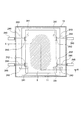
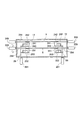
- FIG. 6 is a plan view showing a schematic configuration of a non-film-formed substrate transfer mechanism 24 and a film-formed substrate transfer mechanism 25 provided in a second auxiliary chamber 72.
- FIG. 8 is a cross-sectional view taken along the line XX in FIG.
- FIG. 10 is a schematic diagram illustrating a transfer operation of a substrate 9.
- FIG. 6 is a schematic cross-sectional view illustrating the movement of push-up pins 241 and 251 and hooks 242 and 252 when a substrate 9 is transferred. It is a front cross-sectional schematic diagram explaining the structure of the conventional tray conveyance type in-line film-forming apparatus.
- FIG. 1 is a front view showing a schematic configuration of a tray transfer type in-line film forming apparatus according to an embodiment of the present invention.
- the substrate 9 is temporarily moved when the substrate 9 is carried in and out between the film forming chamber 4 in which the film forming process is performed on the surface of the substrate 9 and the atmosphere side and the film forming chamber 4.
- a plurality of vacuum chambers 6, 71, 72, 73, 4, and 8 including the load lock chamber 6 disposed are vertically arranged along the direction of transport of the substrate 9.
- the substrate 9 is horizontally placed on the trays 11 and 12, and is transported along a transport line set so as to penetrate the chamber groups 6, 71, 72, 73, 4 and 8 to form a film. It is like that.
- the configuration of the chamber groups 6, 71, 72, 73, 4, and 8 will be specifically described.
- the load lock chamber 6 and the first, second, and third auxiliary chambers 71, 72, and 73 are sequentially arranged from the left side when viewed from the front.
- the film forming chamber 4 and the reversing chamber 8 are provided.
- Gate valves 30 are provided between the load lock chamber 6 and the first auxiliary chamber 71, between the third auxiliary chamber 73 and the film forming chamber 4, and between the film forming chamber 4 and the inversion chamber 8, respectively.
- a load station 90 is provided on the left side of the load lock chamber 6 for attaching and detaching the substrate 9 to and from the tray 11 in the atmosphere.
- a gate valve 30 is provided on the left wall of the load lock chamber 6 for loading and unloading the tray 11 with the load station 90.
- Each of the chambers 6, 71, 72, 73, 4 and 8 is an airtight vacuum vessel, and is exhausted to a predetermined ultimate pressure by a dedicated or combined exhaust system (not shown).
- the major feature of this embodiment is that the substrate 9 is circulated between the load lock chamber 6 and the atmosphere side for loading / unloading the substrate 9 to / from the apparatus, the substrate 9 is held during film formation, and the vacuum is always maintained.
- a film forming tray (hereinafter referred to as a film forming tray) 12 that circulates in an atmosphere is used. This point will be specifically described below.
- FIG. 2 is a schematic perspective view illustrating the configuration of the load lock tray 11 and the film formation tray 12. Both the load lock tray 11 and the film forming tray 12 are used in different places, and the configuration is basically the same.
- the load lock tray 11 and the film formation tray 12 (hereinafter collectively referred to as “tray” as necessary) are rectangular frame-shaped members as a whole.
- a step is provided at the inner edge of the frame, and the substrate 9 is placed on the trays 11 and 12 while being embedded in the step.
- the substrate 9 to be film-formed in the apparatus of this embodiment is a glass substrate for a display device such as a liquid crystal display or a plasma display.
- a substrate 9 is held by an arm having a vacuum suction mechanism while the upper surface is vacuum-sucked, and the arm is lowered from a predetermined position to release the vacuum suction, thereby being inserted into the trays 11 and 12. It is supposed to be placed.
- the substrate 9 may be placed on the trays 11 and 12 while holding the edge of the substrate 9 by a plurality of arms whose lower ends are bent in an L shape. In this case, a concave portion is formed on the upper surface of the trays 11 and 12 as a space for retracting the bent lower end portion of the arm.
- the trays 11 and 12 in this embodiment are transported by tray transport systems 21 and 22 that employ a rack and pinion mechanism.
- a rack 10 is provided along the line.
- the rack 10 has an elongated plate shape, and is fixed downward from one side of the tray so that the width direction thereof is vertical.
- a screw thread is formed along the direction of one side at the lower end of the rack 10.
- the trays 11 and 12 are conveyed along the direction of this one side.
- FIG. 3 is a schematic perspective view illustrating the configuration of the tray conveyance system.
- the major feature of the apparatus of this embodiment is that the load is transported by allowing a plurality of load lock trays 11 to be transported along a load lock transport line set so as to pass through the load lock chamber 6 and the auxiliary chambers 71 and 72.
- a load-lock tray transport system and a film-formation tray transport system are transport mechanisms 101, 102, 103 that horizontally move trays 11, 12 on which a substrate 9 is placed.
- 104, 105, 106, 107, 108, 109, 110 are arranged along the transport line.
- the load-lock tray transport system is disposed in the load-lock chamber 6 and the first transport mechanism 101 disposed at the position of the load station 90 on the left side of the load-lock chamber 6.
- a transport mechanism 106 disposed in the film forming tray transport system.
- the film forming tray transport system includes a fifth transport mechanism 105 and a sixth transport mechanism 106 disposed in the second auxiliary chamber 72, a seventh transport mechanism 107 disposed in the third transport chamber 73, and a component.
- An eighth transport mechanism 108 and a ninth transport mechanism 109 disposed in the film chamber 4 and a tenth transport mechanism 110 disposed in the reversing chamber 8 are configured.
- the fifth transport mechanism 105 and the sixth transport mechanism 106 are used both as a load lock tray transport system and a film formation tray transport system.
- FIG. 3 is a perspective view showing a schematic configuration of the fourth transport mechanism 104 shown in FIG.
- the fourth transport mechanism 104 includes a pinion 201 that meshes with the rack 10 of the tray 11 shown in FIG.
- a pinion holding plate 202 that holds the pinion 201, an auxiliary gear 203 that meshes with the pinion 201, and an auxiliary It mainly includes a rotation introducing rod 204 that transmits a driving force to the pinion 201 via a gear 203 and a support roller 205 on which the tray 11 that is moved by the driving of the pinion 201 is placed.
- the fourth transport mechanism 104 includes a total of twelve support rollers 205, six on each side of the transport line.
- Elongated base plates 200 extending in the direction of the transport line are provided on both sides of the transport line.
- the roller holder 207 is fixed upright on the base plate 200 or the auxiliary plate 206 fixed to the base plate 200.
- Each support roller 205 is held by a roller holding body 267 so as to be rotatable around a horizontal rotation axis. When the tray 11 on which the edges on both sides are placed on each support roller 205 is moved, each support roller 205 is vertically moved and rotated with the movement.
- the rack 10 (not shown in FIG. 3) meshing with the pinion 201 is sandwiched between a pair of sandwiching rollers 208.
- the pair of sandwiching rollers 208 is supported on a roller support 209 so as to be rotatable around a vertical rotation axis.
- the roller support 209 is a plate material assembled in a T-shape as a whole, and is fixed upright on one base plate 200.
- a plurality of pairs of sandwiching rollers 208 are provided and are arranged at predetermined intervals along the direction of the transport line.
- the rotation introduction rod 204 is held by the introduction rod holder 210.
- the introduction rod holder 210 is a substantially square plate material, and is fixed upright on the auxiliary base plate 200 fixed on one base plate 200.
- the introduction rod holder 210 is provided with a through hole through which the rotation introduction rod 204 passes.
- the introduction rod holding body 210 has a bearing in a through portion of the rotation introduction rod 204, and holds the rotation introduction rod 204 in a state where it can rotate.
- the pinion holding plate 202 has a through-hole through which the rotation introducing rod 204 penetrates at substantially the center, and the rotation introducing rod 204 penetrates through a bearing. Accordingly, the donion holding plate 202 is held by the introduction rod holding body 210 via the rotation introduction rod 204.
- the auxiliary gear 203 is fixed to the tip of the rotation introducing rod 204.
- a rotation driving source such as a motor is connected to the rear end of the rotation introducing rod 204 via a gear mechanism (not shown). The gear mechanism and the rotational drive source are arranged in the first auxiliary chamber 71.
- the fourth transport mechanism 104 shown in FIG. 3 is provided with a vertical movement mechanism for moving the tray 11 in the vertical direction. That is, as shown in FIG. 3, a support plate 211 is provided below the two base plates 200. The two base plates 200 are supported by a plurality of support columns 212 fixed on the support plate 211. Further, the tip of the vertical drive rod 212 shown in FIG. 1 is fixed to the lower surface of the support plate 211. The vertical drive rod 212 extends vertically downward from the support plate 211 and penetrates the bottom plate portion of the first auxiliary chamber 71 in an airtight manner.
- a sealing member such as a mechanical seal that achieves hermetic sealing while allowing the vertical drive rod 212 to move up and down is provided at a penetrating portion of the vertical drive rod 212.
- a vertical drive source (shown in FIG. 1) 213 provided outside the first auxiliary chamber 71 is connected to the vertical drive rod 212 so that the vertical drive rod 212 moves up and down by the vertical drive source 213. It has become.
- the vertical drive source 213, one using fluid pressure such as an air cylinder can be adopted.
- the vertical drive source 212 may be configured by a motor that rotates a long cylindrical rod in which the vertical drive rod 212 is configured by a ball screw and the lower end of the ball screw meshes internally.
- Such a set of the vertical drive rod 212 and the vertical drive source 213 is provided in the first transport mechanism 101 and the third auxiliary chamber 73 provided at the position of the load station 90 on the atmosphere side, as shown in FIG.
- the seventh transport mechanism 107 and the tenth transport mechanism 110 provided in the reversing chamber 8 are also provided.
- the other transport mechanisms 102, 103, 105, 106, 108, 109 are not provided.
- the pinion 201 is fixed to one end of the pinion holding plate 202 as shown in FIG.
- One end of a coil spring 214 is fixed to the other end of the pinion holding plate 202.
- the coil spring 214 extends downward, and the lower end is fixed to the auxiliary base plate 200.
- the pinion holding plate 202 can be rotated by a predetermined angle about the center rotation introducing rod 204 as a rotation axis.
- the coil spring 214 is extended. In this state, the elasticity of the coil spring 214 works to rotate the pinion holding plate 202 in the reverse direction. That is, it works to raise the pinion 201.
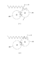
- FIG. 4 is a diagram showing the operation of the coil spring 214 and the pinion holding plate 202 constituting the correcting means shown in FIG.
- the tray 11 is transported by the second transport mechanism 102 shown in FIG. 1, reaches the position of the fourth transport mechanism 104, and is transported by the fourth transport mechanism 104 this time.
- the leading end of the rack 10 of the tray 11 that has meshed with the pinion 201 of the second transport mechanism reaches the pinion 201 of the fourth transport mechanism 104 and meshes with it, and is driven by a rotation drive source (not shown) of the fourth transport mechanism 104.
- the tray 11 moves.
- the pinion 201 In the case where the pinion 201 is directly connected to the rotation introducing rod 204, when the rack 10 and the pinion 201 first mesh with each other, if the tooth crest of the rack 10 and the tooth crest of the pinion 201 collide with each other, the pinion 201 Since there is no play, the collision reaction occurs in the tray 11. That is, the tray 11 floats due to the reaction of the collision, and then falls and meshes the teeth of the rack 10 and the teeth of the pinion 201.
- the substrate 9 is only placed on the step of the tray 11 and inserted into the tray.
- substrate 9 is thin, and a level
- the transport mechanisms 105, 107, 108, 109, and 110 that constitute the film forming tray transport system also employ a rack and pinion mechanism, but if the substrate 9 is detached from the tray 12 in this configuration, the substrate 9 tilts when riding on the outside of the step of the tray 12, and the film thickness distribution during film formation may be deteriorated.
- the pinion 201 is held by the rotatable pinion holding plate 202 and there is play, and the pinion 201 descends even if the tooth crest of the rack 10 and the tooth crest of the pinion 201 collide with each other. Therefore, the trays 11 and 12 do not float. Therefore, the above-described lifting of the substrate 9 from the trays 11 and 12 does not occur.
- the configuration in which the rack 10 is sandwiched between the pair of sandwiching rollers 208 has an effect of stabilizing the meshing between the rack 10 and the pinion 201. That is, when the tray 11 is transported from the upstream side of the transport line, the tray 11 may be displaced in the width direction (horizontal direction perpendicular to the transport line). In this state, the rack 10 is also displaced with respect to the pinion 201, so that the rack 10 does not mesh with the pinion 201 and there is a possibility that a transport error will occur. However, as can be seen from FIG. 3, the rack 10 of the tray 11 that has moved from the upstream side is first sandwiched between the sandwiching rollers 208 and then meshed with the pinion 201.
- the deviation in the width direction is corrected when being sandwiched between the sandwiching rollers 208, and the rack 10 reaches the pinion 201 in a state where the position is always in the correct width direction. For this reason, the rack 10 does not mesh with the pinion 201 and an accident that causes a conveyance error does not occur. Further, there is no accident that the meshing is disengaged after the meshing.
- FIG. 5 is a front view schematically illustrating a transfer line (load lock side transfer line) 231 of the load lock tray transfer system.
- the load lock side transfer line 231 is set to be endless across the load station 90, the load lock chamber 6, the first auxiliary chamber 71, and the second auxiliary chamber 72.
- FIG. 6 is a front view schematically illustrating a transport line of the film forming tray transport system (hereinafter referred to as a film forming side transport line).
- the film forming side transfer line 232 is set to be endless across the second auxiliary chamber 72, the third auxiliary chamber 73, the film forming chamber 4, and the inversion chamber 8. More specifically, there is an upper horizontal transfer line that starts from an upper position in the second auxiliary chamber 72 and passes through the third auxiliary chamber 73 and the film forming chamber 4 to reach the reversal chamber 8. Further, in the reversing chamber 8, there is a vertical transfer line set to lower the film forming tray 12 from the upper position to the lower position.
- the load lock tray 11 and the film formation tray 12 are formed while the load lock tray 11 and the film formation tray 12 are conveyed along the endless transfer lines 231 and 232 as described above.
- the substrate 9 is transferred to the film tray 12 to form a film. That is, an undeposited substrate transfer mechanism 24 for transferring the undeposited substrate 9 from the load-lock tray 11 on which the undeposited substrate 9 is placed to the deposition tray 12 and the undeposited substrate 9 are loaded.
- the film-forming substrate transfer mechanism 25 is provided for transferring the film-formed substrate 9 from the film-forming tray 12 to the load-lock tray 11.
- the undeposited substrate transfer mechanism 24 and the deposited substrate transfer mechanism 25 are provided in the second auxiliary chamber 72.
- FIG. 7 is a plan view showing a schematic configuration of the undeposited substrate transfer mechanism 24 and the deposited substrate transfer mechanism 25 provided in the second auxiliary chamber 72
- FIG. 8 is a line XX in FIG. It is sectional drawing seen in the arrow direction.
- the undeposited substrate transfer mechanism 24 includes an undeposited substrate push-up pin 241 that pushes up the undeposited substrate 9 placed on the load lock tray 11 and an undeposited substrate push-up pin 241. It is mainly composed of an undeposited substrate hook 242 that temporarily supports the undeposited substrate 9 that has been pushed up.
- the film-formed substrate transfer mechanism 25 is pushed up by a film-formed substrate push-up pin 251 and a film-formed substrate push-up pin 251 that push up the film-formed substrate 9 placed on the film-formation tray 12. It is mainly composed of a film-formed substrate hook 252 that temporarily supports the formed film-formed substrate 9.
- the undeposited substrate push-up pin 241 is held at one end of the undeposited substrate pin holder 243 in a horizontal posture.
- the film-formed substrate push-up pin 251 is positioned directly below the non-film-form substrate push-up pin 241 and is held at one end of the film-formed substrate pin holder 253 in a horizontal posture.
- the other end of the non-film-formed substrate pin holder 243 and the other end of the film-formed substrate pin holder 253 are fixed to the driven rod 26 in a vertical posture.
- the driven rod 26 extends vertically downward, penetrates the bottom plate of the second auxiliary chamber 72 in an airtight manner, and its lower end reaches the lower side of the second auxiliary chamber 72.
- a sealing member such as a mechanical seal that achieves hermetic sealing while allowing the driven rod to move up and down is provided.
- a pin drive source 261 is connected to the lower end of the driven rod 26.
- a device using fluid pressure such as an air cylinder can be adopted, and a combination of a ball screw and a motor can be adopted. It is also possible to adopt.
- the four non-film-form substrate push-up pins 241 and four film-form substrate push-up pins 251 are provided so as to push up the four corners of the substrate 9.
- the four pin drive sources 261 it is necessary to perform sufficient adjustment and control so that they operate at the same time with the same stroke.
- a rod support plate that supports the four driven rods 26 as a whole may be provided, and a drive source may be provided below the center of the rod support plate to push up the rod support plate. This configuration is preferable because the adjustment and control are not necessary.
- the undeposited substrate hook 242 is a member having a square shape in a plan view and an L shape in a side view, as shown in FIG.
- the undeposited substrate hook 242 is fixed to the tip of the undeposited substrate hook holder 244 in a horizontal posture.
- the non-film-form substrate hook holder 244 is a rod-shaped member and penetrates the side wall portion of the second auxiliary chamber 72 in an airtight manner.
- a sealing member such as a mechanical seal that achieves hermetic sealing while allowing horizontal movement of the non-film-form substrate hook holder 244 is provided at a penetrating portion of the non-film-form substrate hook holder 244.
- a hook drive source 245 is connected to the rear end of the non-film-form substrate hook holder 244. As with the pin drive source 261, the hook drive source 245 can employ an air cylinder or the like, and a combination of a ball screw and a motor is also possible.
- the non-deposited substrate hooks 242 are provided at four positions so that the substrate 9 can be supported at the four corners. Each of them is provided with an undeposited substrate hook holder 244 and a hook drive source 245.
- the four hook driving sources 245 are simultaneously driven, the two opposing non-film-formed substrate hooks 242 approach each other and stop at a predetermined position.
- the distance between the two non-film-formed substrate hooks 242 at the stopped position, more precisely, the distance between the L-shaped step portions of the two non-film-formed substrate hooks 242 matches the width of the substrate 9. It has become. That is, the stroke of the non-film-formed substrate hook 242 is set so as to support the edge in the width direction of the substrate 9 at the level difference between the two non-film-formed substrate hooks 242 facing each other.
- the four corners of the substrate 9 are supported using the four non-film-formed substrate hooks 242 as in the case of the push-up pins 241 and 251, but when the substrate 9 becomes larger or thinner. It is preferable to use a larger number of undeposited substrate hooks 242. Further, a total of four film-formed substrate hooks 252 are provided directly below each non-film-formed substrate hook 242.
- the film-formed substrate hook 252 has the same configuration as the non-film-formed substrate hook 242 and is an L-shaped member that is fixed to the tip of the film-formed substrate hook holder 254.
- a hook drive source 255 is connected to the rear end of the film-formed substrate hook holder 254, and the film-formed substrate 9 is supported at the four corners by driving the hook drive source 255. Yes.
- FIG. 9 is a schematic diagram illustrating the transfer operation of the substrate 9, and FIG. 10 is a schematic cross-sectional view illustrating the movement of the push-up pins 241 and 251 and the hooks 242 and 252 when the substrate 9 is transferred. is there. (1) to (8) in FIG. 9 show that the transfer operation proceeds in this order.
- X is drawn in the portion of the gate valve 10 in FIG. 9, it means that the gate valve 30 is closed, and when X is not drawn, the gate valve 30 is open. Means that.
- the non-film-formed substrate 9 is drawn in white, and the film-formed substrate 9 is drawn with hatching.
- FIG. 9 (1) shows the operating state of the present apparatus at a certain moment.
- the load lock tray 11 on which the non-film-formed substrate 9 is placed is located in the upper position in the load lock chamber 6.
- a film forming tray 12 on which the transfer of the non-film-formed substrate 9 has been completed is positioned at the upper position in the second auxiliary chamber 72.
- the load-lock tray 11 where the transfer of the film-formed substrate 9 has been completed is located. Further, at the lower position in the film forming chamber 4, the film forming process on the substrate 9 placed on the film forming tray 12 is in progress.
- a first load-lock tray transfer line (first transfer line, upper side) and a second load-lock tray transfer line (second transfer line) extending over the chambers 6, 71, 72 on the left side of FIG. , The lower side). From the first processing tray transfer line (third transfer line, upper side) and the second processing tray transfer line (fourth transfer line, lower side) extending to the chambers 4, 73, 72 on the right side There is a processing tray transport line.
- the film-forming tray 12 that was in the upper position in the second auxiliary chamber 72 is moved to the upper position in the third auxiliary chamber 73, and in the second auxiliary chamber 72.
- the load lock tray 11 located at the lower position moves to the lower position of the first auxiliary chamber 71.
- the gate valve 30 between the third auxiliary chamber 73 and the film forming chamber 4 and the gate valve 30 between the load lock chamber 6 and the first auxiliary chamber 71 are opened.
- the film-forming tray 12 that was in the upper position of the third auxiliary chamber 73 is moved to the upper position of the film-forming chamber 4, and is moved to the lower position of the first auxiliary chamber 71.
- the existing load lock tray 11 moves to the lower position of the load lock chamber 6.
- the load lock tray 11 on which the undeposited substrate 9 is placed is positioned on the upper side, and the load lock tray on which the deposited substrate 9 is placed. 11 is located on the lower side.
- a film forming tray 12 on which an undeposited substrate 9 is placed is located on the upper side, and a film forming tray 12 on which a substrate 9 being formed is placed on the lower side. .
- the load lock tray 11 located at the upper position of the load lock chamber 6 moves to the upper position of the first auxiliary chamber 71.
- the gate valve 30 between the load lock chamber 6 and the first auxiliary chamber 71 is closed.
- the gate valve between the load lock chamber 6 and the load station (not shown in FIG. 9) opens, and the load lock tray 11 located at the lower position in the load lock chamber 6 moves to the load station 90.
- the film forming tray 12 located at the lower position of the film forming chamber 4 moves to the third auxiliary chamber 73.
- the gate valve 30 between the third auxiliary chamber 73 and the film forming chamber 4 is closed.
- the gate valve between the film forming tray 12 and the reversing chamber (not shown in FIG. 9) opens, and the film forming tray 12 located at the upper position in the film forming chamber 4 moves to the reversing chamber 8. .
- FIG. 10 (1) shows the state of FIG. 9 (4).
- the pin driving sources 261 operate simultaneously, and the non-film-formed substrate pin holder 243 and the film-formed substrate pin holder 253 are simultaneously raised by a predetermined distance.
- the non-film-form substrate push-up pin 241 pushes the non-film-form substrate 9 up to a predetermined height
- the film-form substrate push-up pin 251 pushes the film-form substrate 9 Push up to the specified height.
- each pin drive source 261 operates in the reverse direction, and each push-up pin descends a predetermined distance.
- FIG. 10 (3) the non-film-formed substrate 9 is supported by the non-film-formed substrate hook 242 and the film-formed substrate 9 is supported by the film-formed substrate hook 252. It will be in the state.
- FIG. 9 (5) shows the state of FIG. 10 (3).
- the load lock tray 11 moves so as to return toward the first auxiliary chamber 71
- the film forming tray 12 moves so as to return toward the third auxiliary chamber 73.
- the vertical drive rod 212 is driven by the vertical drive source 213 provided on the lower side of the first auxiliary chamber 71 shown in FIG.
- the auxiliary chamber 71 descends from the upper position to the lower position.
- the vertical drive rod 212 is driven by the drive source 213 provided below the third auxiliary chamber 73 to raise the entire seventh transport mechanism 107, so that the film forming tray 12 is moved into the third auxiliary chamber 73. Ascend from the lower position to the upper position.
- the load lock tray 11 enters the chamber 71 from the chamber 72, where the transport direction is changed and returned to the chamber 72 again (fifth). Transport line).
- the film forming tray 12 enters the chamber 73 from the chamber 72, where the transport direction is changed and returned to the chamber 72 again (sixth transport line).
- a film-formed substrate and an untreated substrate are placed, respectively.
- the tray 11 on which the film-formed substrate is placed is taken out from the chamber 6 by the second transfer line, and the tray 12 on which the unprocessed substrate is placed is sent to the chamber 4 for film formation.
- the load lock tray 11 moves to the second auxiliary chamber 72 along the lower transfer line, and the film forming tray 12 moves to the second auxiliary chamber 72 along the upper transfer line.
- the load lock tray 11 is positioned at the lower position of the second auxiliary chamber 72 and the film forming tray 12 is positioned at the upper position. This state is completely opposite to that shown in FIG.
- the pin driving sources 261 shown in FIGS. 7 and 8 operate simultaneously, and the non-film-forming substrate pin holder 243 and the film-forming substrate pin holder 253 are simultaneously raised by a predetermined distance.
- the non-film-formed substrate 9 is again supported on the non-film-formed substrate push-up pins 241, and the film-formed substrate 9 is supported on the film-formed substrate push-up pins 251.
- the hook drive sources 245 and 255 move the hook holders 244 and 254 in the opposite directions and retract the hooks 242 and 252.
- each pin drive source 261 lowers each pin holder 243, 253, and accordingly, each push-up pin 241, 251 descends so that the undeposited substrate 9 and the deposited substrate 9 simultaneously have the same predetermined stroke. Only descend.
- the non-film-formed substrate 9 is placed on the film-forming tray 12, and the film-formed substrate 9 is placed on the load-lock tray 11. This completes the series of transfer operations, and the above-described operations (the operations of FIGS. 9 (2) to (8)) are repeated.
- an undeposited substrate 9 is placed on the loadlock tray 11 on the load station 90 provided on the left side of the loadlock chamber 6 on the atmosphere side, and the deposited substrate 9 is loaded on the loadlock tray 11.
- a mechanism is provided to remove from.
- the load station 90 takes out the non-film-formed substrates 9 one by one from a substrate storage shelf (not shown) that stores a plurality of substrates 9 and transfers them to the load lock tray 11.
- a robot capable of removing the film-formed substrate 9 from 11 and returning it to the substrate storage shelf is provided.
- the robot includes an arm having a vacuum suction pad at the tip, for example, and transports the substrate 9 between the substrate storage shelf and the load lock tray 11 while vacuum sucking the substrate 9.
- the “load station” means a place where the substrate 9 is mounted on the tray 11 or the substrate 9 is removed from the tray 11. In some cases, the operator loads and removes the substrate 9 by hand without using the robot as described above. In this case, the place where the operation is performed is the load station.
- the film forming chamber 4 is provided with a film forming means.
- This film forming means forms a predetermined thin film on the surface of the substrate 9 by vacuum deposition.
- a crucible 42 is provided below the film forming chamber 4.
- the crucible 42 is disposed in a crucible chamber 41 that is airtightly connected to the film forming chamber 4 through a connecting cylinder 43.
- the crucible 42 is filled with a material to be formed, and the material is heated and evaporated by a method such as electron beam irradiation.
- the crucible chamber 41 can be evacuated to the same extent as the film forming chamber 4 by a dedicated or dual-purpose exhaust system. Further, the connecting cylinder film forming chamber 4 has an opening at a portion where the connecting cylinder 43 is connected, and the material evaporated in the crucible chamber 41 reaches the surface of the substrate 9 through the opening. A thin film is formed on the surface of the substrate 9.
- the connection cylinder 43 may be provided with a shutter mechanism that is closed when the film forming process is interrupted.
- the plurality of load lock trays 11 circulate along the endless loadlock-side transfer line 231 and the plurality of film formation trays 12 have the endless film formation.
- the substrate 9 is exchanged between the load lock tray 11 and the film forming tray 12, and film formation is performed on the substrate 9 placed on the film forming tray 12. Is done.
- the gate valve 30 on the atmosphere side of the load lock chamber 6 is closed, and the gate valve 30 on the first auxiliary chamber 71 side is opened.
- the load-lock tray 11 on which the film-formed substrate 9 is placed is sent to the lower position in the load-lock chamber 6 by the fourth transport mechanism 104 and the third transport mechanism 103. It is done.
- the vertical drive source 213 attached to the first transport mechanism 101 at the position of the load station 90 lowers the first transport mechanism 101 to be positioned at the lower position, and the fourth transport mechanism in the first auxiliary chamber 71.
- a vertical drive source 213 attached to 104 raises the fourth transport mechanism 104 and positions it in the upper position.
- the load lock tray 11 on which the non-film-formed substrate 9 is placed is sent to the upper position in the first auxiliary chamber 71 by the second transport mechanism 102 and the fourth transport mechanism 104, and the atmosphere side of the load lock chamber 6
- the gate valve 30 is opened, and the load lock tray 11 on which the film-formed substrate 9 is placed is sent to the lower position of the load station 90 by the third transport mechanism 103 and the first transport mechanism 101.
- the gate valves 30 on both sides of the load lock chamber 6 are closed. This state corresponds to the state shown in FIG.
- the film forming tray 12 on which the undeposited substrate 9 is placed by the transfer reaches the upper position of the film forming chamber 4 by the seventh transport mechanism 107 and the eighth transport mechanism 108 as shown in FIG.
- Another film forming tray 12 is already positioned below the film forming chamber 4, and a film forming process on the substrate 9 placed on the film forming tray 12 is in progress.
- the vertical drive source 213 attached to the seventh transport mechanism 107 in the third auxiliary chamber 73 operates to lower the seventh transport mechanism 107 to the lower position.
- the film forming tray 12 at the lower position in the film forming chamber 4 where the film forming process has been performed is sent to the lower position in the third auxiliary chamber 73 by the ninth transfer mechanism 109 and the seventh transfer mechanism 107.
- the gate valve 30 between the third auxiliary chamber 73 and the film forming chamber 4 is closed, and as shown in FIGS. 9 (4) to 9 (8), between the film forming tray 12 and the load lock tray 11. The mutual transfer operation of the substrate 9 is performed.
- the tenth transport mechanism 110 is located at the upper position by the vertical drive source 213 attached to the tenth transport mechanism 110 in the reversing chamber 8, and the film formation tray located at the upper position in the film formation chamber 4. 12 is sent to the upper position in the reversing chamber 8 by the eighth transport mechanism 108 and the tenth transport mechanism 110. Then, the vertical drive source 213 attached to the tenth transport mechanism 110 in the reversing chamber 8 lowers the tenth transport mechanism ll 0, and moves the film forming tray 12 on which the non-film-formed substrate 9 is placed below the reversing chamber 8. Set to the side position.
- the film forming tray 12 is sent to the lower position in the film forming chamber 4 by the tenth transport mechanism 110 and the ninth transport mechanism 109, and the gate valve 30 between the film forming chamber 4 and the reversing chamber 8. Is closed and the film forming process is started. This corresponds to the state shown in FIG. The film forming process continues throughout the mutual transfer operation, and the above operation is repeated.
- the substrate 9 is placed on the load lock tray 11 at the upper position of the load station 90, temporarily waits in the load lock chamber 6, and then passes through the first auxiliary chamber 71 to the upper position of the second auxiliary chamber 72. Reach.
- the substrate 9 is transferred to the film forming tray 12 in the second auxiliary chamber 72, and then reaches the upper position of the film forming chamber 4 through the third auxiliary chamber 73.
- the substrate 9 moves to the upper position of the reversing chamber 8, descends in the reversing chamber 8 and is positioned at the lower position, and then reaches the lower position of the film forming chamber 4.
- the substrate 9 While another substrate 9 is being transferred, the substrate 9 is positioned at the lower position of the film formation chamber 4 and a film having a required thickness is formed. Then, after passing through the third auxiliary chamber 73 and reaching the lower position of the second auxiliary chamber 72 and being transferred from the film forming tray 12 to the load lock tray 11, the first auxiliary chamber 71 and the load lock chamber 6 are transferred. To the lower position of the load station 90. Then, it is removed from the load lock tray 11 at the load station 90.
- a tray suitable for the substrate is prepared and replaced with the tray before the film formation is performed.
- the trays 11 and 12 shown in FIG. 2 are exchanged for another tray in which the shape and size of the stepped portions are adapted to the shapes and sizes of the different substrates.
- the configuration other than the shape and size of the stepped portion such as the configuration of the rack 10 is the same.
- the respective load mechanisms 11, 102, 103, 104, 105, 106, 107, 108, 109, 110 are operated to sequentially load the load lock tray 11 and the film forming tray 12.
- the prepared another tray is positioned at a predetermined standby position in the apparatus from the load station 90 using each of the transport mechanisms 101, 102, 103, 104, 105, 106, 107, 108, 109, 110. .
- the circulation of the tray is started and a film forming process for another substrate is performed.
- a large or different substrate may be placed. In this case, the tray is not replaced.
- the tray transfer type in-line film forming apparatus of the present embodiment related to the configuration and operation described above has a load lock tray transfer system in addition to the film formation tray transfer system, and only when the film forming process is performed in the apparatus.
- the substrate 9 is also carried on the load lock tray 11 during the loading / unloading operation with the atmosphere via the load lock chamber 6. For this reason, it is possible to easily form a film on the substrates 9 having different shapes and sizes using the same apparatus.
- the trays 11 and 12 are transported by the transport mechanism that employs the rack and pinion mechanism.
- substrate 9 enlarges and the weight of the trays 11 and 12 and the board
- substrate may become a problem, and this problem is remarkable when a board
- Such a problem does not occur because the substrate 9 is transported by using it.
- the sizes of the trays 11 and 12 can be determined as standard, and the trays 11 and 12 can be prepared by loading the substrates 9 having different sizes.
- the transport mechanism employs a configuration in which a number of small disk-shaped transport rollers with a rotation axis set in the horizontal direction perpendicular to the direction of the transport line are arranged on both sides of the transport line along the direction of the transport line. It is also possible to do. By rotating the transport roller, the tray having both ends placed on the transport roller can be moved along the transport line. However, in the case of this configuration, if the weight of the substrate 9 or the trays 11 and 12 is increased, the trays 11 and 12 may slide on the transport rollers, which may be inferior in terms of transport stability and reliability. is there.
- the apparatus of the present embodiment is an inter-back type apparatus. That is, the loading / unloading operation of the substrate 9 is performed from one side of the apparatus, and the substrate 9 is configured to be reversed and returned within the apparatus.
- This inter-back type device has the following advantages.
- a conventional apparatus as shown in FIG. 11 carries the substrate 9 from one side of the apparatus and carries it out from the other side. In such a configuration, since the loading / unloading position of the substrate 9 is different, two loader robots are required, and there is a problem that the cost and the occupied space are increased. In addition, even in the case of manual operation, there is a problem that the work location of the operator is divided into nika places and workability is not good.
- an inter-back type apparatus such as this embodiment carries in and out from the same side, only one robot is needed, which helps to reduce costs and save space. Helps improve.
- the gate valve 30 is provided between the third auxiliary chamber 73 and the film forming chamber 4 and between the film forming chamber 4 and the inversion chamber 8.
- the third auxiliary chamber 73 and the film forming chamber 4 and the inversion chamber 8 and the film forming chamber 4 are isolated from each other except when necessary. Therefore, it is possible to suppress the deposition material evaporated in the deposition chamber 4 from diffusing into the auxiliary chambers 71, 72, 73 and the inversion chamber 8 and being deposited on the exposed surface inside. Since the auxiliary chambers 71, 72, 73 and the reversing chamber 8 are provided with a mechanism for driving up and down, if the deposits increase, the possibility of peeling due to impact is relatively high. If the peeled deposit adheres to the surface of the substrate 9, there is a risk of causing defects such as local film thickness anomalies, but this possibility is low in the apparatus of this embodiment.
- the load lock tray 11 conveyed via the first and second auxiliary chambers 71 and 72 once returns to the atmosphere side and then returns to the vacuum side again.
- the surface of the deposit is altered by oxidation or the like when it goes out to the atmosphere side, and then again on it. Evaporate will accumulate.
- deposits including such altered layers are stacked, the deposits are unstable and easily peel off.
- the accumulation of evaporates on the load lock tray 11 is suppressed. Such a problem does not occur originally.
- the first, second, and three auxiliary chambers 71, 72, and 73 are used, but these may be used as one large auxiliary chamber.
- a gate valve may be provided at a boundary portion between the auxiliary chambers 71, 72, and 73. In particular, when a gate valve is provided between the second auxiliary chamber 72 and the third auxiliary chamber 73, the effect of preventing the accumulation of evaporated substances on the load lock tray 11 is great.
- the load lock chamber 6 was one, and carrying in from the atmosphere side and carrying out to the atmosphere side were performed via this load lock chamber 6,
- Two load lock chambers are provided. The loading and unloading may be performed by different routes.
- two load lock chambers may be stacked to form the above-described inter-back configuration, or the carry-out side may be opposite to the carry-in side.
- the load lock tray may be used only in the load lock chamber on the carry-in side, or may be used only in the load lock chamber on the single carry-out side.
- the configuration of the film forming chamber 4 is not limited to the above-described vacuum vapor deposition, and a configuration in which a film is formed by a method such as sputtering or CVD may be employed.
- the film forming means includes a target made of a film forming material, a sputtering power source for sputtering the target, and a gas introduction system for introducing a gas for causing sputtering discharge.
- CVD in the case of a configuration in which CVD is performed, it includes a gas introduction system for introducing a predetermined reactive gas and an energy supply system for applying energy such as heat or high frequency to the introduced gas.
- the substrate 9 can be formed by not only a glass substrate for display but also a plastic substrate for printed circuit, a circular substrate for information recording disk, and the like.
Landscapes
- Container, Conveyance, Adherence, Positioning, Of Wafer (AREA)
Abstract
大気側と成膜チャンバーとの間の搬送の際に一時的に基板が配置されるチャンバーにおいてもトレイを使用することで、形状や大きさの異なる基板についても同じ装置で容易に成膜処理できるようにする。成膜チャンバー(4)とロードロックチャンバー(6)との間には、未成膜基板用移載機構(24)及び成膜済み基板移載機構(25)を備えた補助チャンバー(72)が設けられている。補助チャンバー(71)~(73)及び成膜チャンバー(4)は、常時真空に維持される。未成膜の基板(9)は、ロードロック用トレイ(11)に載せられてロードロックチャンバー(6)から補助チャンバー(72)に搬送され、ロードロック用トレイ(11)から成膜用トレイ(12)に移載される。成膜済みの基板(9)は、成膜用トレイ(12)に載せられて成膜チャンバー(4)から補助チャンバー(72)に搬送され、成膜用トレイ(12)からロードロック用トレイ(11)に移載される。
Description
本願の発明は、基板をトレイに載せて搬送して基板の表面に所定の薄膜を作成するトレイ搬送式の成膜装置であって、成膜チャンバーを含む複数の真空チャンバーを搬送の方向に沿って縦設したインライン式の成膜装置に関する。
基板の表面に薄膜を作成する成膜装置には、真空蒸着装置、スパッタリング装置、CVD(化学的気相成長)装置等の各種のタイプのものが知られている。これらの装置では、基板をトレイに載せて搬送して基板の表面に所定の薄膜を作成するトレイ搬送式の装置が従来より知られている。また、成膜チャンバーを含む複数の真空チャンバーを搬送の方向に沿って縦設したインライン式の装置も従来より知られている。
図11は、従来のトレイ搬送式インライン成膜装置の構成を説明する正面断面概略図である。図11に示す装置は、水平な姿勢のトレイ1の上に基板9を載せ、このトレイ1をトレイ搬送系2によって水平に搬送しながら成膜する装置である。この装置は、基板9の搬送の順に、基板搬入チャンバー31と、成膜チャンバー4と、基板搬出チャンバー32とを、ゲートバルブ30を介在させながら縦設した構成である。
成膜チャンバー4内には、複数のトレイ1を無終端状の搬送ラインに沿って循環させるトレイ搬送系2が設けられている。基板9は、搬入側基板搬送系51によって大気側から基板搬入チャンバー31を経由して成膜チャンバー4に搬送され、トレイ1に搭載された後に成膜チャンバー4内を搬送されて成膜されるよう構成されている。その後、基板9はトレイ1から取り去られ、搬出側基板搬送系52によって基板搬出チャンバー32を経由して大気側に搬出されるようになっている。
トレイ1は枠状であり、その内周面には基板9の形状及び大きさに適合する段差を有している。成膜する基板9に合わせて適宜トレイ1が選択され、成膜チャンバー4内に配置されて用いられる。尚、トレイ1の外形は共通化されており、それに合うようにトレイ搬送系2が構成されている。
特開平9-279341号公報
上述した従来のトレイ搬送式インライン成膜装置では、トレイ1が成膜チャンバー4内の無終端状の搬送ラインに沿って循環し、大気側には取り出されないため、トレイ1に大気成分が付着しないというメリットもある。トレイ1には基板9と同様に膜が堆積するため、トレイ1に酸素等の大気成分が付着すると、膜表面に酸化層等の汚染層が形成されて膜が剥がれやすくなる問題があるが、上記装置ではこのような問題がない。
しかしながら、上記従来の装置では、成膜チャンバー4内に基板9を搬入する搬入側基板搬送系51や成膜チャンバー4から基板を搬出する搬出側基板搬送系52は、トレイ1を使用していない。即ち、搬送コロの上に基板9を直接載せて搬送している。搬送コロは、水平方向の回転軸の周りに回転可能な状態で搬送方向の両側に沿って多数並べられている。そして、両側の搬送コロの間隔は、搬送する基板9の幅に合うように定められている。このため、幅が大きく異なる基板9については同じ搬送コロで搬送できず、同じ装置を使用して成膜処理を使用することができない。また、幅の最も狭い基板に合わせて搬送コロの間隔を設定することも考えられるが、幅の広い基板になると、基板の表面の成膜領域に搬送コロが接触する状態なってしまうため、この構成は採用不可である。
従来の装置は、成膜チャンバー4内でトレイ1を使用しつつも、上記のように基板搬入チャンバー31や基板搬出チャンバー32ではトレイをしていないため、形状や大きさの異なる基板9を同じ装置で処理することは実質的に困難であった。
本願の発明は、このような課題を解決するために為されたものであり、大気側と成膜チャンバーとの間の搬送の際に一時的に基板が配置されるチャンバーにおいてもトレイを使用することで、形状や大きさの異なる基板についても同じ装置で容易に成膜処理できるようにすることを目的としている。
本願の発明は、このような課題を解決するために為されたものであり、大気側と成膜チャンバーとの間の搬送の際に一時的に基板が配置されるチャンバーにおいてもトレイを使用することで、形状や大きさの異なる基板についても同じ装置で容易に成膜処理できるようにすることを目的としている。
上記課題を解決するため、本発明に従うトレイ搬送式インライン処理装置は、減圧雰囲気にて基板表面に処理を施す手段を備えた処理チャンバーを含む処理側チャンバー、大気側から基板を搬入し及び大気側へ基板を搬出する際に大気に開放され、そして基板がその内に配置された際に大気から隔絶された減圧雰囲気にされるロードロックチャンバー、及び処理チャンバーとロードロックチャンバーとの間に配置され、処理側チャンバーとロードロックチャンバーとにそれぞれゲートバルブを介して接続された補助チャンバーとからなる。
そして、そのロードロックチャンバーと補助チャンバー内に亘って延在し、ロードロック用トレイをロードロックチャンバーと補助チャンバーとの間で双方向に移動させるロードロック用トレイ搬送ライン、処理側チャンバーと補助チャンバー内に亘って延在し、処理用トレイを該処理側チャンバーと該補助チャンバーとの間で双方向に移動させる処理用トレイ搬送ライン、及び補助チャンバー内に配置された基板移載機構であって、補助チャンバー内でロードロック用トレイ搬送ラインにあるロードロック用トレイ上の基板を処理用トレイ搬送ラインにある処理用トレイ上に移載し、処理用トレイ搬送ラインにある処理用トレイ上の基板を該ロードロック用トレイ搬送ラインにあるロードロック用トレイ上に移載する基板移載機構を含む。
実施例では、ロードロック用トレイ搬送ラインは、ロードロック用トレイをロードロックチャンバーから補助チャンバーへと移動させる第1のロードロック用トレイ搬送ラインと、ロードロック用トレイを補助チャンバーから該ロードロックチャンバーへと移動させる第2のロードロック用トレイ搬送ラインとからなり、処理用トレイ搬送ラインは、処理用トレイを補助チャンバーから処理側チャンバーへと移動させる第1の処理用トレイ搬送ラインと処理用トレイを処理側チャンバーから補助チャンバーへと移動させる第2の処理用トレイ搬送ラインとからなり、基板移載機構は、第1のロードロック用トレイ搬送ラインにおいて補助チャンバー内へ移動されたロードロック用トレイを、第2のロードロック用トレイ搬送ラインへと移して第2の処理用トレイ搬送ラインにある処理用トレイ上の処理済基板をそこに載置し、及び第2の処理用トレイ搬送ラインにおいて補助チャンバー内へ移動された処理用トレイを、第1の処理用トレイ搬送ラインへと移して第1のロードロック用トレイ搬送ラインにあるロードロック用トレイ上の未処理基板をそこに載置している。
又、第1のロードロック用トレイ搬送ラインと処理用トレイ搬送ラインは、未処理基板を載置したロードロック用トレイと処理用トレイをそれぞれ移動させており、第2のロードロック用トレイ搬送ラインと第2の処理用トレイ搬送ラインは、処理済基板を載置したロードロック用トレイと処理用トレイをそれぞれ移動させている。
ロードロック用トレイ搬送ライン又は処理用トレイ搬送ラインの機構の実施例は、ラックアンドピニオン機構によりロードロック用トレイ又は処理用トレイを搬送するものであり、そのラックアンドピニオン機構は、ロードロック用トレイ又は処理用トレイに設けられたラックと、ラックに噛み合うピ二オンとからなるものであり、ピニオンがラックに最初に噛み合う際にラックの歯の山とピニオンの歯の山とがぶつかる衝撃でピニオンがラックから離れてその後再び戻ってピニオンがラックに噛み合うようにする補正手段とを備えている。
本発明の他の側面に従う基板処理装置は、減圧雰囲気にて基板の表面を処理する処理手段を備えた処理側チャンバーを含む処理側チャンバー、大気側から基板を搬入し及び大気側へ基板を搬出する際に大気に開放され、そして基板がその内に配置された際に大気から隔絶された減圧雰囲気にされるロードロックチャンバー、処理チャンバーと前記ロードロックチャンバーとの間に位置する第1補助チャンバー、第2補助チャンバー及び第3補助チャンバーを有する複数の補助チャンバー、ロードロックチャンバー、第1補助チャンバー及び第2補助チャンバー内に亘って延在し、ロードロックチャンバーから第1補助チャンバーに向かい、そして第2補助チャンバーに向かう第1搬送ライン、ロードロックチャンバー、第1補助チャンバー及び第2補助チャンバー内に亘って延在し、第2チャンバーから第1チャンバーに向かい、そしてロードロックチャンバーに向かい、第1搬送ラインと相違する搬送ラインを有する第2搬送ライン、第2補助チャンバー、第3補助チャンバー及び処理チャンバー内に亘って延在し、第2補助チャンバーから第3補助チャンバーに向かい、そして処理側チャンバーに向かう第3搬送ライン、第2補助チャンバー、第3補助チャンバー及び処理側チャンバー内に亘って延在し、処理チャンバーから第3補助チャンバーに向かい、そして第2補助チャンバーに向かい、第3搬送ラインと相違する搬送ラインを有する第4搬送ライン、第2補助チャンバーから第1補助チャンバーに向かい、第1補助チャンバー内で搬送方向を変換し、該変換された方向から前記第2補助チャンバーに向かう第5搬送ライン、第2補助チャンバーから第3補助チャンバーに向かい、第3補助チャンバー内で搬送方向が変換され、該変換された方向から第2補助チャンバーに向かう第6搬送ライン、基板を載置した第1トレイを第1搬送ラインに沿って第2補助チャンバーまで搬送し、第2補助チャンバー内で該載置した基板を第1トレイから離脱させ、第1トレイを第5搬送ラインに沿って第2補助チャンバーまで搬送し、第2補助チャンバー内で予め配置されている処理済み基板を第1トレイに載置し、第1トレイを第2搬送ラインに沿ってロードロックチャンバーまで搬送する第1駆動手段、並びに、処理済み基板を載置した第2トレイを第4搬送ラインに沿って第2補助チャンバーまで搬送し、第2補助チャンバー内で載置した処理済み基板を第2トレイから離脱させ、第2補助トレイを第6搬送ラインに沿って第2補助チャンバーまで搬送し、第2補助チャンバー内で第1トレイから離脱された基板を第2トレイに載置し、第2トレイを第3搬送ラインに沿って処理側チャンバーまで搬送する第2駆動手段を有している。
実施例にあって、第1補助チャンバーは、第1トレイを上昇又は下降させるための位置変換手段を有しており、第3補助チャンバーは、第2トレイを上昇又は下降させるための位置変換手段を有しており、基板の上に薄膜を形成する手段を有し、処理チャンバーは、基板の表面をエッチング処理する手段を有し、又は、基板の表面をクリーニング処理する手段を有している。
さらに、第4補助チャンバー及び第4補助チャンバー内に位置する第7搬送ラインを有し、第7搬送ラインは、第4チャンバー内において、第3搬送ラインと第4搬送ラインとを接続する搬送ラインを有している。
そして、そのロードロックチャンバーと補助チャンバー内に亘って延在し、ロードロック用トレイをロードロックチャンバーと補助チャンバーとの間で双方向に移動させるロードロック用トレイ搬送ライン、処理側チャンバーと補助チャンバー内に亘って延在し、処理用トレイを該処理側チャンバーと該補助チャンバーとの間で双方向に移動させる処理用トレイ搬送ライン、及び補助チャンバー内に配置された基板移載機構であって、補助チャンバー内でロードロック用トレイ搬送ラインにあるロードロック用トレイ上の基板を処理用トレイ搬送ラインにある処理用トレイ上に移載し、処理用トレイ搬送ラインにある処理用トレイ上の基板を該ロードロック用トレイ搬送ラインにあるロードロック用トレイ上に移載する基板移載機構を含む。
実施例では、ロードロック用トレイ搬送ラインは、ロードロック用トレイをロードロックチャンバーから補助チャンバーへと移動させる第1のロードロック用トレイ搬送ラインと、ロードロック用トレイを補助チャンバーから該ロードロックチャンバーへと移動させる第2のロードロック用トレイ搬送ラインとからなり、処理用トレイ搬送ラインは、処理用トレイを補助チャンバーから処理側チャンバーへと移動させる第1の処理用トレイ搬送ラインと処理用トレイを処理側チャンバーから補助チャンバーへと移動させる第2の処理用トレイ搬送ラインとからなり、基板移載機構は、第1のロードロック用トレイ搬送ラインにおいて補助チャンバー内へ移動されたロードロック用トレイを、第2のロードロック用トレイ搬送ラインへと移して第2の処理用トレイ搬送ラインにある処理用トレイ上の処理済基板をそこに載置し、及び第2の処理用トレイ搬送ラインにおいて補助チャンバー内へ移動された処理用トレイを、第1の処理用トレイ搬送ラインへと移して第1のロードロック用トレイ搬送ラインにあるロードロック用トレイ上の未処理基板をそこに載置している。
又、第1のロードロック用トレイ搬送ラインと処理用トレイ搬送ラインは、未処理基板を載置したロードロック用トレイと処理用トレイをそれぞれ移動させており、第2のロードロック用トレイ搬送ラインと第2の処理用トレイ搬送ラインは、処理済基板を載置したロードロック用トレイと処理用トレイをそれぞれ移動させている。
ロードロック用トレイ搬送ライン又は処理用トレイ搬送ラインの機構の実施例は、ラックアンドピニオン機構によりロードロック用トレイ又は処理用トレイを搬送するものであり、そのラックアンドピニオン機構は、ロードロック用トレイ又は処理用トレイに設けられたラックと、ラックに噛み合うピ二オンとからなるものであり、ピニオンがラックに最初に噛み合う際にラックの歯の山とピニオンの歯の山とがぶつかる衝撃でピニオンがラックから離れてその後再び戻ってピニオンがラックに噛み合うようにする補正手段とを備えている。
本発明の他の側面に従う基板処理装置は、減圧雰囲気にて基板の表面を処理する処理手段を備えた処理側チャンバーを含む処理側チャンバー、大気側から基板を搬入し及び大気側へ基板を搬出する際に大気に開放され、そして基板がその内に配置された際に大気から隔絶された減圧雰囲気にされるロードロックチャンバー、処理チャンバーと前記ロードロックチャンバーとの間に位置する第1補助チャンバー、第2補助チャンバー及び第3補助チャンバーを有する複数の補助チャンバー、ロードロックチャンバー、第1補助チャンバー及び第2補助チャンバー内に亘って延在し、ロードロックチャンバーから第1補助チャンバーに向かい、そして第2補助チャンバーに向かう第1搬送ライン、ロードロックチャンバー、第1補助チャンバー及び第2補助チャンバー内に亘って延在し、第2チャンバーから第1チャンバーに向かい、そしてロードロックチャンバーに向かい、第1搬送ラインと相違する搬送ラインを有する第2搬送ライン、第2補助チャンバー、第3補助チャンバー及び処理チャンバー内に亘って延在し、第2補助チャンバーから第3補助チャンバーに向かい、そして処理側チャンバーに向かう第3搬送ライン、第2補助チャンバー、第3補助チャンバー及び処理側チャンバー内に亘って延在し、処理チャンバーから第3補助チャンバーに向かい、そして第2補助チャンバーに向かい、第3搬送ラインと相違する搬送ラインを有する第4搬送ライン、第2補助チャンバーから第1補助チャンバーに向かい、第1補助チャンバー内で搬送方向を変換し、該変換された方向から前記第2補助チャンバーに向かう第5搬送ライン、第2補助チャンバーから第3補助チャンバーに向かい、第3補助チャンバー内で搬送方向が変換され、該変換された方向から第2補助チャンバーに向かう第6搬送ライン、基板を載置した第1トレイを第1搬送ラインに沿って第2補助チャンバーまで搬送し、第2補助チャンバー内で該載置した基板を第1トレイから離脱させ、第1トレイを第5搬送ラインに沿って第2補助チャンバーまで搬送し、第2補助チャンバー内で予め配置されている処理済み基板を第1トレイに載置し、第1トレイを第2搬送ラインに沿ってロードロックチャンバーまで搬送する第1駆動手段、並びに、処理済み基板を載置した第2トレイを第4搬送ラインに沿って第2補助チャンバーまで搬送し、第2補助チャンバー内で載置した処理済み基板を第2トレイから離脱させ、第2補助トレイを第6搬送ラインに沿って第2補助チャンバーまで搬送し、第2補助チャンバー内で第1トレイから離脱された基板を第2トレイに載置し、第2トレイを第3搬送ラインに沿って処理側チャンバーまで搬送する第2駆動手段を有している。
実施例にあって、第1補助チャンバーは、第1トレイを上昇又は下降させるための位置変換手段を有しており、第3補助チャンバーは、第2トレイを上昇又は下降させるための位置変換手段を有しており、基板の上に薄膜を形成する手段を有し、処理チャンバーは、基板の表面をエッチング処理する手段を有し、又は、基板の表面をクリーニング処理する手段を有している。
さらに、第4補助チャンバー及び第4補助チャンバー内に位置する第7搬送ラインを有し、第7搬送ラインは、第4チャンバー内において、第3搬送ラインと第4搬送ラインとを接続する搬送ラインを有している。
以下に説明する通り、本発明によれば、処理(成膜)用トレイ搬送系に加えてロードロック用トレイ搬送系を有し、装置内での成膜処理の際のみならずロードロックチャンバーを経由した大気側との間の搬入搬出動作の際にも基板はトレイに載せられて搬送されるようになっている。このため、形状や大きさの異なる基板についても同じ装置で容易に成膜処理でき、汎用性の点で極めて優れた装置となる。
また、成膜チャンバーと補助チャンバーとは開放が必要な時以外は隔絶されるので、補助チャンバー内の露出面やロードロック用トレイヘの成膜材料の堆積が抑制されので、堆積物の剥離に起因した問題が防止されるという効果がある。
また、ラックアンドピニオン機構によりトレイがされるので、基板が大型化してトレイや基板の重量が大きくなっても安定して確実に搬送が行えるという効果がある。
また、ラックに最初の噛み合う際にラックの歯の山とピニオンの歯の山とがぶつかる衝撃でピニオンがラックから離れた後に再び戻ってラックにピニオンが噛み合うようにする補正手段が設けられているので、ラックとピニオンの最初の噛み合いの際にトレイが浮いてしまう問題が発生しないという効果が得られる。
また、インターバック式の構成なので、ロードロック用トレイヘの基板の搭載やロードロック用トレイからの基板の取り去り動作を行うための構成について、低コスト化や省スペース化が図られたり、又は作業性が向上したりする効果が得られる。
また、成膜チャンバーと補助チャンバーとは開放が必要な時以外は隔絶されるので、補助チャンバー内の露出面やロードロック用トレイヘの成膜材料の堆積が抑制されので、堆積物の剥離に起因した問題が防止されるという効果がある。
また、ラックアンドピニオン機構によりトレイがされるので、基板が大型化してトレイや基板の重量が大きくなっても安定して確実に搬送が行えるという効果がある。
また、ラックに最初の噛み合う際にラックの歯の山とピニオンの歯の山とがぶつかる衝撃でピニオンがラックから離れた後に再び戻ってラックにピニオンが噛み合うようにする補正手段が設けられているので、ラックとピニオンの最初の噛み合いの際にトレイが浮いてしまう問題が発生しないという効果が得られる。
また、インターバック式の構成なので、ロードロック用トレイヘの基板の搭載やロードロック用トレイからの基板の取り去り動作を行うための構成について、低コスト化や省スペース化が図られたり、又は作業性が向上したりする効果が得られる。
11 ロードロック用トレイ
12 成膜用トレイ
10 ラック
24 未成膜基板用移載機構
25 成膜済み基板用移載機構
4 成膜チャンバー
42 坩堝
6 ロードロックチャンバー
71 第一補助チャンバー
72 第二補助チャンバー
73 第三補助チャンバー
8 反転チャンバー
9 基板
90 ロードステーション
12 成膜用トレイ
10 ラック
24 未成膜基板用移載機構
25 成膜済み基板用移載機構
4 成膜チャンバー
42 坩堝
6 ロードロックチャンバー
71 第一補助チャンバー
72 第二補助チャンバー
73 第三補助チャンバー
8 反転チャンバー
9 基板
90 ロードステーション
以下、本願発明の実施形態について説明する。
図1は、本願発明の実施形態に係るトレイ搬送式インライン成膜装置の概略構成を示す正面図である。図1に示す装置は、基板9の表面に対する成膜処理が行われる成膜チャンバー4と、大気側と成膜チャンバー4との間で基板9の搬入搬出を行う際に基板9が一時的に配置されるロードロックチャンバー6とを含む複数の真空チャンバー6,71,72,73,4,8を基板9の搬送の方向に沿って縦設した構成である。基板9は、トレイ11,12の上に水平に載せられ、上記チャンバー群6,71,72,73,4,8を貫くように設定された搬送ラインに沿って搬送されて成膜が行われるようになっている。
図1は、本願発明の実施形態に係るトレイ搬送式インライン成膜装置の概略構成を示す正面図である。図1に示す装置は、基板9の表面に対する成膜処理が行われる成膜チャンバー4と、大気側と成膜チャンバー4との間で基板9の搬入搬出を行う際に基板9が一時的に配置されるロードロックチャンバー6とを含む複数の真空チャンバー6,71,72,73,4,8を基板9の搬送の方向に沿って縦設した構成である。基板9は、トレイ11,12の上に水平に載せられ、上記チャンバー群6,71,72,73,4,8を貫くように設定された搬送ラインに沿って搬送されて成膜が行われるようになっている。
チャンバー群6,71,72,73,4,8の構成について具体的に説明すると、正面からみて左側から順に、ロードロックチャンバー6、第一第二第三の三つの補助チャンバー71,72,73、成膜チャンバー4、反転チャンバー8となっている。ロードロックチャンバー6と第一補助チャンバー71との間、第三補助チャンバー73と成膜チャンバー4との問、成膜チャンバー4と反転チャンバー8との間には、それぞれゲートバルブ30が設けられている。また、ロードロックチャンバー6の左側には、大気中でトレイ11への基板9の着脱を行うロードステーション90が設けられている。ロードロックチャンバー6の左側の壁には、ロードステーション90との間でのトレイ11の出し入れのため、ゲートバルブ30が設けられている。尚、各チャンバー6,71,72,73,4,8は、気密な真空容器であり、専用又は兼用の不図示の排気系によって所定の到達圧力まで排気されるようになっている。
本実施形態の大きな特徴点は、装置への基板9の搬入搬出のためロードロックチャンバー6と大気側との間で循環するロードロック用トレイ11と、成膜時に基板9を保持し、常に真空雰囲気で循環する成膜用のトレイ(以下、成膜用トレイ)12とが用いられている点である。以下、この点を具体的に説明する。
まず、ロードロック用トレイ11と成膜用トレイ12との構成について図2を用いて説明する。図2は、ロードロック用トレイ11及び成膜用トレイ12の構成を説明する斜視概略図である。
ロードロック用トレイ11も成膜用トレイ12も、用いられる場所が異なるのみであり、その構成は基本的に同様である。図2に示すように、ロードロック用トレイ11及び成膜用トレイ12(以下、必要に応じて「トレイ」と総称する)は、全体が方形の枠状の部材である。枠の内縁には段差が設けられており、基板9はこの段差に填り込んだ状態でトレイ11,12に載せられるようになっている。
ロードロック用トレイ11も成膜用トレイ12も、用いられる場所が異なるのみであり、その構成は基本的に同様である。図2に示すように、ロードロック用トレイ11及び成膜用トレイ12(以下、必要に応じて「トレイ」と総称する)は、全体が方形の枠状の部材である。枠の内縁には段差が設けられており、基板9はこの段差に填り込んだ状態でトレイ11,12に載せられるようになっている。
本実施形態の装置において成膜処理される基板9は、液晶ディスプレイやプラズマディスプレイ等の表示装置用のガラス基板である。このような基板9は、真空吸着機構を備えたアームに上面が真空吸着されながら保持され、アームが所定位置から下降して真空吸着を解除することにより、上記トレイ11,12に填り込んで載置されるようになっている。尚、下端がL字状に折れ曲がった複数のアームによって基板9の縁を保持しながらトレイ11,12に基板9を載置する場合がある。この場合は、トレイ11,12の上面には、アームの折れ曲がった下端部分が退避するスペースとしての凹部が形成される。
本実施形態におけるトレイ11,12は、後述するようにラックアンドピニオン機構を採用したトレイ搬送系21,22によって搬送されるようになっており、図2に示すように、トレイ11,12の一辺に沿ってラック10が設けられている。ラック10は、細長い板状であり、その幅方向が垂直になるようにトレイの一辺から下方に向けて固定されている、ラック10の下端には、一辺の方向に沿ってねじ山が形成されており、この一辺の方向に沿ってトレイ11,12が搬送されるようになっている。
次に、図1及び図3を用いて、上記ロードロック用トレイ11又は成膜用トレイ12を搬送するトレイ搬送系の構成について説明する。図3は、トレイ搬送系の構成を説明する斜視概略図である。
本実施形態の装置の大きな特徴点は、ロードロックチャンバー6と補助チャンバー71,72とを通るように設定されたロードロック用搬送ラインに沿って複数のロードロック用トレイ11をさせて搬送するロードロック用トレイ搬送系と、補助チャンバー72,73と成膜チャンバー4とを通るように設定された成膜用搬送ラインに沿って複数の成膜用トレイ12を搬送する成膜用トレイ搬送系とが設けられている点である。ロードロック用トレイ搬送系及び成膜用トレイ搬送系(以下、必要に応じてトレイ搬送系と総称する)は、基板9を載せたトレイ11,12を水平に移動させる搬送機構101,102,103,104,105,106,107,108,109,110を搬送ラインに沿って並べた構成となっている。
本実施形態の装置の大きな特徴点は、ロードロックチャンバー6と補助チャンバー71,72とを通るように設定されたロードロック用搬送ラインに沿って複数のロードロック用トレイ11をさせて搬送するロードロック用トレイ搬送系と、補助チャンバー72,73と成膜チャンバー4とを通るように設定された成膜用搬送ラインに沿って複数の成膜用トレイ12を搬送する成膜用トレイ搬送系とが設けられている点である。ロードロック用トレイ搬送系及び成膜用トレイ搬送系(以下、必要に応じてトレイ搬送系と総称する)は、基板9を載せたトレイ11,12を水平に移動させる搬送機構101,102,103,104,105,106,107,108,109,110を搬送ラインに沿って並べた構成となっている。
具体的には、図1に示すように、ロードロック用トレイ搬送系は、ロードロックチャンバー6の左側のロードステーション90の位置に配置された第一搬送機構101と、ロードロックチャンバー6内に配置された第二搬送機構102及び第三搬送機構103と、第一補助チャンバー71内に配置された第四搬送機構104と、第二補助チャンバー72内に配置された第五搬送機構105及び第六搬送機構106とから構成されている。また、成膜用トレイ搬送系は、第二補助チャンバー72内に配置された第五搬送機構105及び第六搬送機構106と、第三搬送チャンバー73に配置された第七搬送機構107と、成膜チャンバー4に配置された第八搬送機構108及び第九搬送機構109と、反転チャンバー8に配置された第十搬送機構110とから構成されている。尚、上記説明から明らかなように、第五搬送機構105及び第六搬送機構106は、ロードロック用トレイ搬送系と成膜用トレイ搬送系とに兼用されている。
上述した第一から第十の各搬送機構101,102,103,104,105,106,107,108,109,110は、ラックアンドピニオン機構を採用した構成となっている。これらの搬送機構の構成について、第四搬送機構を例にして説明する。図3は、図1に示す第四搬送機構104の概略構成を示す斜視図である。
図3に示すように、第四搬送機構104は、図2に示すトレイ11のラック10に噛み合うピニオン201と、ピニオン201を保持したピニオン保持板202と、ピニオン201に噛み合う補助ギア203と、補助ギア203を介してピニオン201に駆動力を伝える回転導入棒204と、ピニオン201の駆動によって移動するトレイ11が載る支持コロ205とから主に構成されている。
図3に示すように、第四搬送機構104は、図2に示すトレイ11のラック10に噛み合うピニオン201と、ピニオン201を保持したピニオン保持板202と、ピニオン201に噛み合う補助ギア203と、補助ギア203を介してピニオン201に駆動力を伝える回転導入棒204と、ピニオン201の駆動によって移動するトレイ11が載る支持コロ205とから主に構成されている。
図3に示すように、第四搬送機構104は、搬送ラインの両側に六つずつ計12個の支持コロ205を備えている。搬送ラインの両側には、搬送ラインの方向に延びる細長いベース板200が設けられている。コロ保持体207が、このベース板200又はベース板200に固定された補助板206の上に立てて固定されている。各支持コロ205は、水平な回転軸の周りに回転可能な状態でコロ保持体267に保持されている。各支持コロ205の上に両側の縁が載ったトレイ11が移動すると、移動に伴って各支持コロ205が縦動して回転するようになっている。
ピニオン201に噛み合うラック10(図3中不図示)は、一対の挟みローラ208に挟み込まれるようになっている。一対の挟みローラ208は、垂直な回転軸の周りに回転可能な状態でローラ支持体209の上に支持されている。ローラ支持体209は全体がT字状に組み立てられた板材であり、一方のベース板200の上に立てて固定されている。尚、図3に示すように、挟みローラ208は、複数対設けられており、搬送ラインの方向に沿って所定間隔で並べられている。
回転導入棒204は、導入棒保持体210によって保持されている。導入棒保持体210は、ほぼ方形の板材であり、一方のベース板200の上に固定された補助ベース板200の上に立てて固定されている。導入棒保持体210には、回転導入棒204が貫通する貫通孔が設けられている。導入棒保持体210は回転導入棒204の貫通部分にベアリングを有し、回転導入棒204をそれが回転可能な状態で保持している。
また、ピニオン保持板202も同様に回転導入棒204が貫通する貫通孔をほぼ中央に有しており、回転導入棒204がベアリングを介して貫通している。従って、ドニオン保持板202は、回転導入棒204を介して導入棒保持体210に保持された状態となっている。
補助ギア203は、回転導入棒204の先端に固定されている。回転導入棒204の後端には、不図示のギア機構を介してモータ等の不図示の回転駆動源が接続されている。尚、ギヤ機構や回転駆動源は、第一補助チャンバー71内に配置されている。回転駆動源が駆動されると、回転導入棒204が回転し、この回転が補助ギア203を介してピニオン201に伝えられ、ピニオン201が回転する。ピニオン201の回転によってピニオン201に噛み合っているラック10(図2に示す)が移動し、ラック10とともにトレイ11が一体に水平に移動するようになっている。
補助ギア203は、回転導入棒204の先端に固定されている。回転導入棒204の後端には、不図示のギア機構を介してモータ等の不図示の回転駆動源が接続されている。尚、ギヤ機構や回転駆動源は、第一補助チャンバー71内に配置されている。回転駆動源が駆動されると、回転導入棒204が回転し、この回転が補助ギア203を介してピニオン201に伝えられ、ピニオン201が回転する。ピニオン201の回転によってピニオン201に噛み合っているラック10(図2に示す)が移動し、ラック10とともにトレイ11が一体に水平に移動するようになっている。
また、図3に示す第四搬送機構104は、トレイ11を上下方向に移動させる上下移動機構が付設されている。即ち、図3に示すように、二つのベース板200の下方には、支持板211が設けられている。二つのベース板200は、支持板211の上に固定された複数の支柱212によって支持されている。
また、支持板211の下面には、図1に示す上下駆動棒212の先端が固定されている。この上下駆動棒212は、支持板211から垂直下方に延びており、第一補助チャンバー71の底板部分を気密に貫通している。上下駆動棒212の貫通部分には、上下駆動棒212の上下動を許容しつつ気密封止を達成するメカニカルシール等の封止部材が設けられている。上下駆動棒212には、第一補助チャンバー71外に設けられた上下駆動源(図1に示す)213が接続されており、この上下駆動源213によって上下駆動棒212が上下に移動するようになっている。上下駆動源213としては、エアシリンダ等の流体圧を使用するものが採用できる。また、例えば上下駆動棒212をボールねじで構成し、そのボールねじの下端が内部で噛み合う長尺な円筒ロッドを回転させるモータで上下駆動源213を構成するようにしてもよい。
また、支持板211の下面には、図1に示す上下駆動棒212の先端が固定されている。この上下駆動棒212は、支持板211から垂直下方に延びており、第一補助チャンバー71の底板部分を気密に貫通している。上下駆動棒212の貫通部分には、上下駆動棒212の上下動を許容しつつ気密封止を達成するメカニカルシール等の封止部材が設けられている。上下駆動棒212には、第一補助チャンバー71外に設けられた上下駆動源(図1に示す)213が接続されており、この上下駆動源213によって上下駆動棒212が上下に移動するようになっている。上下駆動源213としては、エアシリンダ等の流体圧を使用するものが採用できる。また、例えば上下駆動棒212をボールねじで構成し、そのボールねじの下端が内部で噛み合う長尺な円筒ロッドを回転させるモータで上下駆動源213を構成するようにしてもよい。
このような上下駆動棒212と上下駆動源213の組は、図1に示すように、大気側のロードステーション90の位置に設けられた第一搬送機構101、第三補助チャンバー73に設けられた第七搬送機構107、反転チャンバー8に設けられた第十搬送機構110にも設けられている。その他の搬送機構102,103,105,106,108,109には、設けられていない。
一方、上述した搬送機構104の構成において、図3に示すように、ピニオン201はピニオン保持板202の一端に固定されている。ピニオン保持板202の他端には、コイルスプリング214の一端が固定されている。コイルスプリング214は、下方に延びており、下端が補助ベース板200に固定されている。ピニオン保持板202は、中央の回転導入棒204を回転軸として所定角度回転可能である。ピニオン201が下降する向きにピニオン保持板202が回転すると、コイルスプリング214は伸びた状態となる。この状態では、コイルスプリング214の弾性は、ピニオン保持板202を逆向きに回転させるよう働く。即ち、ピニオン201を上昇させるよう働く。
上記コイルスプリング214及びピニオン保持板202は、ピニオン201とラック10との噛み合いを良くするための補正手段を構成するものとして採用されている。この補正手段の作用について図4を使用して説明する。図4は、図3に示された補正手段を構成するコイルスプリング214及びピニオン保持板202の作用を示す図である。
トレイ11は、図1に示す第二搬送機構102によって搬送された後、第四搬送機構104の位置に達して、今度は第四搬送機構104によって搬送される。具体的には、第二搬送機構のピニオン201に噛み合っていたトレイ11のラック10の先端が第四搬送機構104のピニオン201に達して噛み合い、第四搬送機構104の不図示の回転駆動源によって駆動されてトレイ11が移動する。
トレイ11は、図1に示す第二搬送機構102によって搬送された後、第四搬送機構104の位置に達して、今度は第四搬送機構104によって搬送される。具体的には、第二搬送機構のピニオン201に噛み合っていたトレイ11のラック10の先端が第四搬送機構104のピニオン201に達して噛み合い、第四搬送機構104の不図示の回転駆動源によって駆動されてトレイ11が移動する。
上記ラック10とピニオン201の最初の噛み合いの際、図4(1)に示すように、ラック10の歯の山とピニオン201の歯の山とがぶつかってしまって正しく噛み合わない場合がある。この場合、ラック10の歯の山とピニオン201の歯の山との衝突によってピニオン201がコイルスプリング214の弾性に逆らって下方に円弧運動する。その後、コイルスプリング214の弾性によってピニオン保持板202が逆向きに(上方に)円弧運動する。そして、図4(2)に示すように、ピニオン201がラック10に正しく噛み合う状態となる。
ピニオン201が回転導入棒204に直結された構成である場合、ラック10とピニオン201の最初の噛み合いの際にラック10の歯の山とピニオン201の歯の山とがぶつかってしまうと、ピニオン201に遊びがないので、ぶつかりの反動はトレイ11に生じてしまう。即ち、ぶつかりの反動によってトレイ11が浮いてしまい、その後落下してラック10の歯とピニオン201の歯とが噛み合う。
一方、図2に示すように、基板9はトレイ11の段差の上に載せてトレイに填め込まれているのみである。そして、基板9の厚さは薄く、段差はその厚さ程度の高さしかない。従って、ラック10の歯の山とピニオン201の歯の山とのぶつかりによってトレイ11が浮いて落下すると、その落下の際に基板9が慣性によってトレイ11から浮き、基板9がトレイ11から外れてしまう恐れがある。最悪の場合、トレイ11から外れて落下してしまう事故が発生する。また、成膜用トレイ搬送系を構成する搬送機構105,107,108,109,110でもラックアンドピニオン機構を採用しているが、この構成においてトレイ12から基板9は外れてしまった場合、基板9がトレイ12の段差の外側に乗り上げることで傾いてしまい、成膜の際の膜厚分布を悪くすることがある。
しかしながら、本実施形態では、上述の通りピニオン201が回転可能なピニオン保持板202によって保持されて遊びがあり、ラック10の歯の山とピニオン201の歯の山とがぶつかってもピニオン201が下降するので、トレイ11,12が浮いてしまうことがない。従って、上述したような基板9のトレイ11,12からの浮き上がり等は生じない。
また、一対の挟みローラ208によってラック10が挟み込まれる構成は、ラック10とピニオン201との噛み合いを安定化させる作用がある。即ち、搬送ラインの上流側からトレイ11が搬送されてきた際、トレイ11は幅方向(搬送ラインに垂直な水平方向)にずれている場合がある。この状態では、ラック10もピニオン201に対してずれているので、ラック10がピニオン201に噛み合わず、搬送エラーになる恐れがある。しかし、図3から分かるように、上流側から移動してきたトレイ11のラック10は、最初に挟みローラ208に挟み込まれ、その後にピニオン201に噛み合う構成となっている。従って、挟みローラ208に挟み込まれる際に幅方向でのずれは補正され、常に正しい幅方向の位置になった状態でラック10がピニオン201に到達することになる。このため、ラック10がピニオン201に噛み合わずに搬送エラーとなる事故は発生しない。また、噛み合った後に、その噛み合いが外れてしまう事故も発生しない。
次に、ロードロック用トレイ搬送系及び成膜用トレイ搬送系の各搬送ラインの構成について図1を用いてさらに詳しく説明する。図5は、ロードロック用トレイ搬送系の搬送ライン(ロードロック側搬送ライン)231を概略的に説明した正面図である。ロードロック側搬送ライン231は、ロードステーション90と、ロードロックチャンバー6と、第一補助チャンバー71と、第二補助チャンバー72とにまたがって無終端状に設定されている。
より具体的に説明すると、ロードステーション90における上側位置から始まってロードロックチャンバー6及び第一補助チャンバー71を通り第二補助チャンバー72に達する上側の水平な搬送ラインがある。そして、その上側の搬送ラインと同じライン上を戻って第一補助チャンバー71に達し、第一補助チャンバー71内で垂直下方に延び、さらに、下側で水平に延びて再び第二補助チャンバー72に達する逆コ状の搬送ラインがある。さらに、第二補助チャンバー72から同じ搬送ライン上を通って第一補助チャンバー71に戻り、そのままロードロックチャンバー6を経由してロードステーション90での下側位置に達する搬送ラインがある。尚、ロードステーション90では、下側位置から上側位置にロードロック用トレイ11を移動させる垂直な搬送ラインが設定されている。
また、図6は、成膜用トレイ搬送系の搬送ライン(以下、成膜側搬送ライン)を概略的に説明した正面図である。成膜側搬送ライン232は、第二補助チャンバー72と、第三補助チャンバー73と、成膜チャンバー4と、反転チャンバー8とにまたがって無終端状に設定されている。
より具体的に説明すると、第二補助チャンバー72における上側位置から始まって第三補助チャンバー73及び成膜チャンバー4を通り反転チャンバー8に達する上側の水平な搬送ラインがある。また、反転チャンバー8では成膜用トレイ12を上側位置から下側位置に下降させるよう設定された垂直な搬送ラインがある。そして、反転チャンバー8内の下側位置から成膜チャンバー4及び第三補助チャンバー73を通って第二補助チャンバー72に達する下側の水平な搬送ラインがある。さらに、その下側の搬送ラインと同じライン上を通って第三補助チャンバー73に戻り、第三補助チャンバー73内で垂直上方に延び、さらに、上側の搬送ラインと同じラインを通って再び第二補助チャンバー72に達するコ状の搬送ラインがある。
より具体的に説明すると、第二補助チャンバー72における上側位置から始まって第三補助チャンバー73及び成膜チャンバー4を通り反転チャンバー8に達する上側の水平な搬送ラインがある。また、反転チャンバー8では成膜用トレイ12を上側位置から下側位置に下降させるよう設定された垂直な搬送ラインがある。そして、反転チャンバー8内の下側位置から成膜チャンバー4及び第三補助チャンバー73を通って第二補助チャンバー72に達する下側の水平な搬送ラインがある。さらに、その下側の搬送ラインと同じライン上を通って第三補助チャンバー73に戻り、第三補助チャンバー73内で垂直上方に延び、さらに、上側の搬送ラインと同じラインを通って再び第二補助チャンバー72に達するコ状の搬送ラインがある。
本実施形態の装置では、上述したようなそれぞれの無終端状の搬送ライン231,232に沿ってロードロック用トレイ11と成膜用トレイ12とを搬送しながら、ロードロック用トレイ11と成膜用トレイ12との問で基板9の移載を行って成膜している。即ち、未成膜の基板9を載せたロードロック用トレイ11からその未成膜の基板9を成膜用トレイ12に移賊する未成膜基板用移載機構24と、成膜済みの基板9を載せた成膜用トレイ12からその成膜済みの基板9をロードロック用トレイ11に移載する成膜済み基板用移載機構25とが備えられている。これらの機構について、以下に説明する。
未成膜基板用移載機構24と成膜済み基板用移載機構25は、第二補助チャンバー72に備えられている。図7は第二補助チャンバー72に備えられた未成膜基板用移載機構24と成膜済み基板用移載機構25の概略構成を示す平面図であり、図8は図7の線X-Xにおける矢印方向で見た断面図である。
図8に示すように、未成膜基板用移載機構24は、ロードロック用トレイ11に載せられた未成膜の基板9を押し上げる未成膜基板用押し上げピン241と、未成膜基板用押し上げピン241によって押し上げられた未成膜の基板9を一時的に支持する未成膜基板用フック242とから主に構成されている。また、成膜済み基板用移載機構25は、成膜用トレイ12に載せられた成膜済みの基板9を押し上げる成膜済み基板用押し上げピン251と、成膜済み基板用押し上げピン251によって押し上げられた成膜済みの基板9を一時的に支持する成膜済み基板用フック252とから主に構成されている。
図8に示すように、未成膜基板用移載機構24は、ロードロック用トレイ11に載せられた未成膜の基板9を押し上げる未成膜基板用押し上げピン241と、未成膜基板用押し上げピン241によって押し上げられた未成膜の基板9を一時的に支持する未成膜基板用フック242とから主に構成されている。また、成膜済み基板用移載機構25は、成膜用トレイ12に載せられた成膜済みの基板9を押し上げる成膜済み基板用押し上げピン251と、成膜済み基板用押し上げピン251によって押し上げられた成膜済みの基板9を一時的に支持する成膜済み基板用フック252とから主に構成されている。
未成膜基板用押し上げピン241は、水平な姿勢の未成膜基板用ピンホルダー243の一端に保持されている。また、成膜済み基板用押し上げピン251は、未成膜基板用押し上げピン241の真下に位置し、水平な姿勢の成膜済み基板用ピンホルダー253の一端に保持されている。未成膜基板用ピンホルダー243の他端と成膜済み基板用ピンホルダー253の他端は、垂直な姿勢の被駆動ロッド26に固定されている。
被駆動ロッド26は、垂直下方に延びており、第二補助チャンバー72の底板を気密に貫通し、その下端は第二補助チャンバー72の下側に達している。被駆動ロッド26の貫通部分には、被駆動ロッドの上下動を許容しつつ気密封止を達成するメカニカルシール等の封止部材が設けられている。そして、被駆動ロッド26の下端には、ピン用駆動源261が接続されている。ピン用駆動源261としては、搬送機構101,104,107,110に設けられた上下駆動源213と同様、エアシリンダ等の流体圧を使用するものが採用でき、ボールねじとモータとの組み合わせを採用することも可能である。
上述した未成膜基板用押し上げピン241、成膜済み基板用押し上げピン251、未成膜基板用ピンホルダー243、成膜済み基板用ピンホルダー253、被駆動ロッド26、及び、ピン用駆動源261の組み合わせば四組設けられており、図7及び図8から分かるように、所定位置に位置したトレイ11,12の四隅に位置するよう配置されている。四つのピン用駆動源261が同時に駆動すると、被駆動ロッド26が上昇し、未成膜基板用押し上げピン241と成膜済み基板用押し上げピン251とが同時に上昇するようになっている。この結果、図8に示すように、未成膜基板9が上昇してロードロック用トレイ11から離れるとともに、成膜済み基板9も上昇して成膜用トレイ12から離れるよう構成されている。
尚、本実施形態では、未成膜基板用押し上げピン241と成膜済み基板用押し上げピン251は、基板9の四隅を押し上げるよう4本ずつ設けられているが、基板9が大きくなった場合や薄くなった場合は、6本や8本等、さらに多く設けるようにすると、基板9の撓み等が無く姿勢が安定するので好適である。
また、四つのピン用駆動源261を設ける上記構成では、それらが同時にタイミング良く同じストロークで動作するよう、充分に調整や制御を行う必要がある。一方、四本の被駆動ロッド26を全体に支持するロッド支持板を設け、このロッド支持板の中央の下側に駆動源を設けてロッド支持板を押し上げるようにしても良い。この構成では、上記調整や制御が不要なので好適である。
また、四つのピン用駆動源261を設ける上記構成では、それらが同時にタイミング良く同じストロークで動作するよう、充分に調整や制御を行う必要がある。一方、四本の被駆動ロッド26を全体に支持するロッド支持板を設け、このロッド支持板の中央の下側に駆動源を設けてロッド支持板を押し上げるようにしても良い。この構成では、上記調整や制御が不要なので好適である。
次に、未成膜基板用フック242は、図8に示すように、平面視が方形で側面視がL字状の部材である。この未成膜基板用フック242は、水平な姿勢の未成膜基板用フックホルダー244の先端に固定されている。未成膜基板用フックホルダー244は棒状の部材であり、第二補助チャンバー72の側壁部分を気密に貫通している。未成膜基板用フックホルダー244の貫通部分には、未成膜基板用フックホルダー244の水平移動を許容しつつ気密封止を達成するメカニカルシール等の封止部材が設けられている。未成膜基板用フックホルダー244の後端には、フック用駆動源245が接続されている。フック用駆動源245は、ピン用駆動源261と同様に、エアシリンダ等が採用でき、ボールねじとモータの組み合わせも可能である。
図7及び図8から分かるように、未成膜基板用フック242は、基板9を四隅で支持できるよう四カ所に設けられている。そして、それぞれに未成膜基板用フックホルダー244とフック用駆動源245とが設けられている。四つのフック用駆動源245が同時に駆動されると、対向する二つの未成膜基板用フック242が互いに近づき、所定位置で停止する。その停止した位置における二つの未成膜基板用フック242の離間距離、より正確には二つの未成膜基板用フック242のL字の段差の部分の離間距離は、基板9の幅に一致するようになっている。つまり、対向する二つの未成膜基板用フック242の段差の部分で基板9の幅方向の縁を支持するよう未成膜基板用フック242のストロークが設定されている。
尚、本実施形態では、押し上げピン241,251と同様に四つの未成膜基板用フック242を使用して基板9の四隅を支持しているが、基板9が大きくなった場合や薄くなった場合にはさらに多くの未成膜基板用フック242を使用すると好適である。
また、成膜済み基板用フック252は、各未成膜基板用フック242の真下に計四つ設けられている。この成膜済み基板用フック252も、未成膜基板用フック242と同様の構成であり、成膜済み基板用フックホルダー254の先端に固定された側面視L字状の部材である。そして、成膜済み基板用フックホルダー254の後端にはフック用駆動源255が接続されており、フック用駆動源255の駆動によって、成膜済み基板9をその四隅で支持するようになっている。
また、成膜済み基板用フック252は、各未成膜基板用フック242の真下に計四つ設けられている。この成膜済み基板用フック252も、未成膜基板用フック242と同様の構成であり、成膜済み基板用フックホルダー254の先端に固定された側面視L字状の部材である。そして、成膜済み基板用フックホルダー254の後端にはフック用駆動源255が接続されており、フック用駆動源255の駆動によって、成膜済み基板9をその四隅で支持するようになっている。
次に、図9及び図10を使用して、基板9の移載動作について説明する。図9は、基板9の移載動作について説明した模式図であり、図10は基板9の移載動作を行う際の押し上げピン241,251及びフック242,252の動きについて説明した断面概略図である。
図9の(1)~(8)は、この順で移載動作が進行することを示している。尚、図9中のゲートバルブ10の部分にXが描かれているところはそのゲートバルブ30が閉であることを意味し、×が描かれていないとことはそのゲートバルブ30が開であることを意味する。また、図9において、未成膜の基板9は白抜きで描かれており、成膜済みの基板9はハッチングを入れて描かれている。
図9の(1)~(8)は、この順で移載動作が進行することを示している。尚、図9中のゲートバルブ10の部分にXが描かれているところはそのゲートバルブ30が閉であることを意味し、×が描かれていないとことはそのゲートバルブ30が開であることを意味する。また、図9において、未成膜の基板9は白抜きで描かれており、成膜済みの基板9はハッチングを入れて描かれている。
まず、図9(1)は、ある瞬間における本装置の動作状態を示している。この状態では、未成膜の基板9を載せたロードロック用トレイ11がロードロックチャンバー6内の上側位置に位置している。そして、第二補助チャンバー72内の上側位置には、未成膜の基板9の移載が完了した成膜用トレイ12が位置している。一方、第二補助チャンバー72内の下側位置には、成膜済みの基板9の移載が完了したロードロック用トレイ11が位置している。さらに、成膜チャンバー4内の下側位置では、成膜用トレイ12に載った基板9への成膜処理が進行している。図9の左側にチャンバー6、71、72に亘って延在する、第1のロードロック用トレイ搬送ライン(第1搬送ライン、上側)と第2のロードロック用トレイ搬送ライン(第2搬送ライン、下側)からなるロードロック用トレイ搬送ラインがある。右側にチャンバー4、73、72に渡って延在する、第1の処理用トレイ搬送ライン(第3搬送ライン、上側)と第2の処理用トレイ搬送ライン(第4搬送ライン、下側)からなる処理用トレイ搬送ラインがある。
次に、図9(2)に示すように、第二補助チャンバー72内の上側位置にあった成膜用トレイ12は第三補助チャンバー73の上側位置に移動し、第二補助チャンバー72内の下側位置にあったロードロック用トレイ11は第一補助チャンバー71の下側位置に移動する。そして、第三補助チャンバー73と成膜チャンバー4との間のゲートバルブ30及びロードロックチャンバー6と第一補助チャンバー71との間のゲートバルブ30が開く。その後、図9(3)に示すように、第三補助チャンバー73の上側位置にあった成膜用トレイ12は成膜チャンバー4の上側位置に移動し、第一補助チャンバー71の下側位置にあったロードロック用トレイ11はロードロックチャンバー6の下側位置に移動する。この図9(3)に示す状態では、ロードロックチャンバー6内では、未成膜の基板9を載せたロードロック用トレイ11が上側に位置し、成膜済みの基板9を載せたロードロック用トレイ11が下側に位置している。また、成膜チャンバー4内では、上側に未成膜の基板9を載せた成膜用トレイ12が位置し、下側に成膜中の基板9を載せた成膜用トレイ12が位置している。
次に、図9(4)に示すように、ロードロックチャンバー6の上側位置にあったロードロック用トレイ11は第一補助チャンバー71の上側位置に移動する。そして、ロードロックチャンバー6と第一補助チャンバー71との問のゲートバルブ30が閉じられる。並行して、ロードロックチャンバー6と図9中不図示のロードステーションとの間のゲートバルブが開き、ロードロックチャンバー6内の下側位置にあったロードロック用トレイ11はロードステーション90に移動する。また、成膜チャンバー4の下側位置にあった成膜用トレイ12は第三補助チャンバー73に移動する。そして、第三補助チャンバー73と成膜チャンバー4との間のゲートバルブ30が閉じられる。並行して、成膜用トレイ12と図9中不図示の反転チャンバーとの間のゲートバルブが開き、成膜チャンバー4内の上側位置にあった成膜用トレイ12は反転チャンバー8に移動する。
図10(1)は、上記図9(4)の状態を示している。この状態で、各ピン用駆動源261が同時に動作し、未成膜基板用ピンホルダー243及び成膜済み基板用ピンホルダー253が同時に所定の距離だけ上昇する。この結果、図10(2)に示すように、未成膜基板用押し上げピン241が未成膜の基板9を所定の高さまで押し上げるとともに、成膜済み基板用押し上げピン251が成膜済みの基板9を所定の高さまで押し上げる。
この状態で、各フック用駆動源245,255動作し、各フックホルダー244,254が同時に前進する。そして、各ピン用駆動源261が逆向きに動作し、各押し上げピンが所定距離下降する。この結果、図10(3)に示すように、未成膜の基板9が未成膜基板用フック242によって支持された状態になるとともに、成膜済みの基板9が成膜済み基板用フック252によって支持された状態となる。
図9(5)は、この図10(3)の状態を示している。この状態で、次に、ロードロック用トレイ11が第一補助チャンバー71に向けて戻るように移動するとともに、成膜用トレイ12が第三補助チャンバー73に向けて戻るように移動する。この結果、図9(6)に示す状態となる。
そして、図1に示す第一補助チャンバー71の下側に設けられた上下駆動源213によって上下駆動棒212が駆動されて第四搬送機構104全体が下降することで、ロードロック用トレイ11が第一補助チャンバー71内の上側位置から下側位置まで下降する。同時に、第三補助チャンバー73の下側に設けられた駆動源213によって上下駆動棒212が駆動されて第七搬送機構107全体が上昇することで、成膜用トレイ12が第三補助チャンバー73内の下側位置から上側位置まで上昇する。この結果、図9(7)に示す状態となる。図9の(5)-(6)-(7)-(8)において、ロードロック用トレイ11はチャンバー72からチャンバー71に入り、そこで搬送方向を変換されて再びチャンバー72に返される(第5搬送ライン)。又、成膜用トレイ12はチャンバー72からチャンバー73に入り、そこで搬送方向を変換されて再びチャンバー72に返される(第6搬送ライン)。返されてきたロードロック用トレイ11と成膜用トレイ12にはそれぞれ成膜済基板と未処理基板が載置されている。成膜済基板の載置されたトレイ11は、第2搬送ラインでチャンバー6からとり出され、未処理基板の載置したトレイ12はチャンバー4へ送られて成膜処理がなされる。
そして、図1に示す第一補助チャンバー71の下側に設けられた上下駆動源213によって上下駆動棒212が駆動されて第四搬送機構104全体が下降することで、ロードロック用トレイ11が第一補助チャンバー71内の上側位置から下側位置まで下降する。同時に、第三補助チャンバー73の下側に設けられた駆動源213によって上下駆動棒212が駆動されて第七搬送機構107全体が上昇することで、成膜用トレイ12が第三補助チャンバー73内の下側位置から上側位置まで上昇する。この結果、図9(7)に示す状態となる。図9の(5)-(6)-(7)-(8)において、ロードロック用トレイ11はチャンバー72からチャンバー71に入り、そこで搬送方向を変換されて再びチャンバー72に返される(第5搬送ライン)。又、成膜用トレイ12はチャンバー72からチャンバー73に入り、そこで搬送方向を変換されて再びチャンバー72に返される(第6搬送ライン)。返されてきたロードロック用トレイ11と成膜用トレイ12にはそれぞれ成膜済基板と未処理基板が載置されている。成膜済基板の載置されたトレイ11は、第2搬送ラインでチャンバー6からとり出され、未処理基板の載置したトレイ12はチャンバー4へ送られて成膜処理がなされる。
次に、ロードロック用トレイ11が下側の搬送ラインに沿って第二補助チャンバー72に移動するととともに、成膜用トレイ12が上側の搬送ラインに沿って第二補助チャンバー72に移動する。この結果、図9(8)に示すように、第二補助チャンバー72の下側位置にロードロック用トレイ11が位置し、上側位置に成膜用トレイ12が位置した状態となる。この状態は、図9(5)とは全く逆の状態である。
この状態で図7及び図8に示す各ピン用駆動源261が同時に動作し、未成膜基板用ピンホルダー243及び成膜基板用ピンホルダー253が同時に所定の距離だけ上昇する。この結果、再び、未成膜基板用押し上げピン241の上に未成膜の基板9が支持され、成膜済み基板用押し上げピン251の上に成膜済みの基板9が支持された状態となる。この状態で、各フック用駆動源245,255が各フックホルダー244,254を逆向きに移動させ、各フック242,252を後退させる。そして、各ピン用駆動源261が各ピンホルダー243,253を下降させ、これに伴い各押し上げピン241,251が下降して未成膜の基板9及び成膜済みの基板9が同時に所定の同じストロークだけ下降する。この結果、図9(1)に示すように、未成膜の基板9が成膜用トレイ12に載り、成膜済みの基板9がロードロック用トレイ11に載った状態となる。これで一連の移載動作は終了であり、以下、上述した動作(図9(2)~(8)の動作)を繰り返す。
次に、図1に戻り、本実施形態の装置の他の部分の構成について説明する。
まず、ロードロックチャンバー6の左側の大気側の位置に設けられたロードステーション90には、未成膜の基板9をロードロック用トレイ11に載せるとともに、成膜済みの基板9をロードロック用トレイ11から取り去る機構が設けられている。具体的には、ロードステーション90は、複数の基板9を収容した不図示の基板収容棚から未成膜の基板9を一枚ずつ取り出してロードロック用トレイ11に移載すとともに、ロードロック用トレイ11から成膜済みの基板9を取り去って基板収容棚に戻すことが可能なロボットが設けられている。このロボットは、例えば真空吸着パッドを先端に有するアームを備えており、基板9を真空吸着しながら基板収容棚とロードロック用トレイ11との間で基板9の搬送を行うようになっている。尚、「ロードステーション」とは、トレイ11への基板9の搭載やトレイ11からの基板9の取り去りを行う場所という意味である。上記のようなロボットを使用せず、オペレータが手で基板9の搭載や取り去りを行う場合もあり、この場合はそれを行う場所がロードステーションである。
まず、ロードロックチャンバー6の左側の大気側の位置に設けられたロードステーション90には、未成膜の基板9をロードロック用トレイ11に載せるとともに、成膜済みの基板9をロードロック用トレイ11から取り去る機構が設けられている。具体的には、ロードステーション90は、複数の基板9を収容した不図示の基板収容棚から未成膜の基板9を一枚ずつ取り出してロードロック用トレイ11に移載すとともに、ロードロック用トレイ11から成膜済みの基板9を取り去って基板収容棚に戻すことが可能なロボットが設けられている。このロボットは、例えば真空吸着パッドを先端に有するアームを備えており、基板9を真空吸着しながら基板収容棚とロードロック用トレイ11との間で基板9の搬送を行うようになっている。尚、「ロードステーション」とは、トレイ11への基板9の搭載やトレイ11からの基板9の取り去りを行う場所という意味である。上記のようなロボットを使用せず、オペレータが手で基板9の搭載や取り去りを行う場合もあり、この場合はそれを行う場所がロードステーションである。
また、成膜チャンバー4は、成膜手段を備えている。この成膜手段は、真空蒸着法によって所定の薄膜を基板9の表面に作成するようになっている。具体的には、成膜チャンバー4の下方には、坩堝42が設けられている。坩堝42は、接続筒43を介して成膜チャンバー4に気密に接続された坩堝チャンバー41内に配置されている.坩堝42には成膜すべき材料が充填されており、電子線照射等の方法によって材料を加熱して蒸発させるようになっている。
坩堝チャンバー41は、専用又は兼用の排気系によって成膜チャンバー4と同程度まで排気可能となっている。また、接続筒成膜チャンバー4は接続筒43を接続した部分に開口を有しており、坩堝チャンバー41内で蒸発した材料がこの開口と通して基板9の表面に達し、この結果、所定の薄膜が基板9の表面に作成されるようになっている。尚、接続筒43には、成膜処理を中断する際に閉じられるシャッタ機構が設けられることがある。成膜の具体例を挙げると、基板9がプラズマディスプレイ用のガラス基板である場合、酸化マグネシウム薄膜を所定の厚さ作成する例が挙げられる。
次に、図1を使用して本実施形態の装置の全体の動作について概略的に説明する。
上述したように、本実施形態の装置では、複数のロードロック用トレイ11が無終端状のロードロック側搬送ライン231に沿って循環し、複数の成膜用トレイ12が無終端状の成膜側搬送ライン232に沿って循環する過程で、ロードロック用トレイ11と成膜用トレイ12との間で基板9の交換が行なわれ、成膜用トレイ12に載った基板9に対して成膜が行われる。
上述したように、本実施形態の装置では、複数のロードロック用トレイ11が無終端状のロードロック側搬送ライン231に沿って循環し、複数の成膜用トレイ12が無終端状の成膜側搬送ライン232に沿って循環する過程で、ロードロック用トレイ11と成膜用トレイ12との間で基板9の交換が行なわれ、成膜用トレイ12に載った基板9に対して成膜が行われる。
まず、ロードロック用トレイ搬送系の動きに重点を置きながら、装置の動作について説明する。図1に示すロードステーション90の位置の第一搬送機構101に付設された上下駆動源213によってロードロック用トレイ11か所定の上側位置に位置しているとき、不図示のロボットによって未成膜の基板9がロードロック用トレイ11に載せられる。次に、ロードロックチャンバー6の大気側のゲートバルブ30が開き、ロードステーション90との間の第一搬送機構101及び第二搬送機構102が動作して、この基板9を載せたロードロック用トレイ11一がロードロックチャンバー6内の上側位置に送られる。この状態は、図9(1)に示す状態に相当している。
次に、ロードロックチャンバー6の大気側のゲートバルブ30が閉じ、第一補助チャンバー71側のゲートバルブ30が開く。そして、図9(3)に示すように、成膜済みの基板9を載せたロードロック用トレイ11が第四搬送機構104及び第三搬送機構103によりロードロックチャンバー6内の下側位置に送られる。
そして、ロードステーション90の位置の第一搬送機構101に付設された上下駆動源213は第一搬送機構101を下降させて下側位置に位置させるとともに、第一補助チャンバー71内の第四搬送機構104に付設された上下駆動源213は第四搬送機構104を上昇させて上側位置に位置させる。次に、未成膜の基板9を載せたロードロック用トレイ11が第二搬送機構102及び第四搬送機構104により第一補助チャンバー71内の上側位置に送られるとともに、ロードロックチャンバー6の大気側のゲートバルブ30が開き、成膜済みの基板9を載せたロードロック用トレイ11が第三搬送機構103及び第一搬送機構101によりロードステーション90の下側位置に送られる。その後、ロードロックチャンバー6の両側のゲートバルブ30は閉じられる。この状態が、図9(4)の状態に相当している。
そして、ロードステーション90の位置の第一搬送機構101に付設された上下駆動源213は第一搬送機構101を下降させて下側位置に位置させるとともに、第一補助チャンバー71内の第四搬送機構104に付設された上下駆動源213は第四搬送機構104を上昇させて上側位置に位置させる。次に、未成膜の基板9を載せたロードロック用トレイ11が第二搬送機構102及び第四搬送機構104により第一補助チャンバー71内の上側位置に送られるとともに、ロードロックチャンバー6の大気側のゲートバルブ30が開き、成膜済みの基板9を載せたロードロック用トレイ11が第三搬送機構103及び第一搬送機構101によりロードステーション90の下側位置に送られる。その後、ロードロックチャンバー6の両側のゲートバルブ30は閉じられる。この状態が、図9(4)の状態に相当している。
次に、ロードステーション90では、成膜済みの基板9をロードロック用トレイ11から取り去る動作が行われる。そして、第一搬送機構101の上下駆動源213が動作してロードステーション90の位置のロードロック用トレイ11を上側位置に上昇させる。そして、このロードロック用トレイ11に対して次の未成膜の基板9を載せる動作が行われる。その後、ロードロックチャンバー6の大気側のゲートバルブ30が開き、このロードロック用トレイ11をロードロックチャンバー6内の上側位置に位置させる。
並行して、第一から第三補助チャンバー71,72,73では、前述したロードロック用トレイllと成膜用トレイ12との間の基板9の相互移載の動作が行われる(図9(5)~(8))。相互移載が終了すると、図9(1)に示す状態となり、ロードロック用トレイ搬送系は、上記動作を繰り返す。
並行して、第一から第三補助チャンバー71,72,73では、前述したロードロック用トレイllと成膜用トレイ12との間の基板9の相互移載の動作が行われる(図9(5)~(8))。相互移載が終了すると、図9(1)に示す状態となり、ロードロック用トレイ搬送系は、上記動作を繰り返す。
次に、成膜用トレイ搬送系の動きに重点を置きながら、装置の動作について説明する。移し替えによって未成膜の基板9が載った成膜用トレイ12は、図9(3)に示すように、第七搬送機構107及び第八搬送機構108によって成膜チャンバー4の上側位置に達する。成膜チャンバー4の下側位置には、別の成膜用トレイ12が既に位置しており、この成膜用トレイ12に載った基板9への成膜処理が進行中である。
次に、第三補助チャンバー73内の第七搬送機構107に付設された上下駆動源213が動作して第七搬送機構107を下側位置まで下降させる。そして、成膜処理をしていた成膜チャンバー4内の下側位置の成膜用トレイ12が第九搬送機構109及び第七搬送機構107により第三補助チャンバー73内の下側位置に送られる。その後、第三補助チャンバー73と成膜チャンバー4との間のゲートバルブ30が閉じられ、図9(4)から(8)に示すように成膜用トレイ12とロードロック用トレイ11との間の基板9の相互移載動作が行われる。
また、反転チャンバー8内の第十搬送機構110に付設された上下駆動源213によって第十搬送機構110が上側位置に位置しており、成膜チャンバー4内の上側位置にあった成膜用トレイ12は、第八搬送機構108及び第十搬送機構110によって反転チャンバー8内の上側位置に送られる。そして、反転チャンバー8内の第十搬送機構110に付設された上下駆動源213は第十搬送機構ll0を下降させ、未成膜の基板9を載せた成膜用トレイ12を反転チャンバー8内の下側位置に位置させる。その後、第十搬送機構110及び第九搬送機構109によってこの成膜用トレイ12が成膜チャンバー4内の下側位置に送られるとともに、成膜チャンバー4と反転チャンバー8との間のゲートバルブ30が閉じられ、成膜処理が開始される。これは、図9(5)の状態に相当している。成膜処理は、上記相互移載動作の間中続き、上記動作を繰り返すことになる。
上述した本装置の動作において、一つの基板9に着目して動きを説明すると、以下のようになる。まず、基板9は、ロードステーション90の上側位置においてロードロック用トレイ11に載せられ、ロードロックチャンバー6で一時待機した後、第一補助チャンバー71を経由して第二補助チャンバー72の上側位置に達する。そして、この基板9は、第二補助チャンバー72で成膜用トレイ12に移載された後、第三補助チャンバー73を経由して、成膜チャンバー4の上側位置に達する。そしてさらに、この基板9は、反転チャンバー8の上側位置に移動し、反転チャンバー8内で下降して下側位置に位置した後、成膜チャンバー4の下側位置に達する。そして、別の基板9の移載動作が行われている間、この基板9は、成膜チャンバー4の下側位置に位置して必要な厚さの成膜が行われる。その後、第三補助チャンバー73を通って第二補助チャンバー72の下側位置に達し、成膜用トレイ12からロードロック用トレイ11に移載された後、第一補助チャンバー71及びロードロックチャンバー6を通ってロードステーション90の下側位置に達する。そして、ロードステーション90でロードロック用トレイ11から取り去られる。
上記本実施形態の装置の動作において、大きさ又は形状の異なる別の基板を成膜処理する場合、その基板に適合したトレイを用意してそのトレイに交換してから成膜処理を行うようにする。具体的には、図2に示すトレイ11,12の段差の部分の形状及び大きさがその異なる基板の形状及び大きさに適合した別のトレイに交換する。尚、ラック10の構成等、段差の部分の形状及び大きさ以外については、すべて同じ構成とされる。
交換の方法について説明すると、まず、各搬送機構101,102,103,104,105,106,107,108,109,110を動作させて各ロードロック用トレイ11及び成膜用トレイ12を順次ロードステーション90の位置に取り出し、装置から取り除く。次に、上記用意した別のトレイをロードステーション90から各搬送機構101,102,103,104,105,106,107,108,109,110を使用して装置内の所定のスタンバイ位置に位置させる。この状態で、上述したようにトレイの循環を開始し、別の基板の成膜処理を行う。
尚、トレイの構成によっては、大きな又は形状の異なる基板を載せられるようになっている場合もあり、この場合には、トレイの交換は行わない。
尚、トレイの構成によっては、大きな又は形状の異なる基板を載せられるようになっている場合もあり、この場合には、トレイの交換は行わない。
上述した構成及び動作に係る本実施形態のトレイ搬送式インライン成膜装置では、成膜用トレイ搬送系に加えてロードロック用トレイ搬送系を有し、装置内での成膜処理の際のみならずロードロックチャンバー6を経由した大気側との間の搬入搬出動作の際にも基板9はロードロック用トレイ11に載せられて搬送されるようになっている。このため、形状や大きさの異なる基板9についても同じ装置で容易に成膜処理できる。
また、上述したように、本実施形態の装置では、ラックアンドピニオン機構を採用した搬送機構によってトレイ11,12が搬送されるようになっている。このため、基板9が大型化してトレイ11,12や基板9の重量が大きくなっても安定して確実に搬送を行うことができる。
尚、トレイを用いずに基板のみを搬送する場合、基板のたわみや反りが問題となる場合があり、この問題は基板が大型化すると顕著であるが、本実施形態では、トレイ11,12を用いて基板9を搬送するのでこのような問題はない。また、基板のみを搬送する場合、異なる基板サイズに搬送機構を構成する必要があり、機構的に複雑になり易く、搬送も困難となるが、上記実施形態のようにトレイ11,12を用いて搬送する場合、トレイ11,12のサイズを標準で決めておき、そのようなトレイ11、12につき異なるサイズの基板9を載せることができるものを用意することで対応ができる。
また、上述したように、本実施形態の装置では、ラックアンドピニオン機構を採用した搬送機構によってトレイ11,12が搬送されるようになっている。このため、基板9が大型化してトレイ11,12や基板9の重量が大きくなっても安定して確実に搬送を行うことができる。
尚、トレイを用いずに基板のみを搬送する場合、基板のたわみや反りが問題となる場合があり、この問題は基板が大型化すると顕著であるが、本実施形態では、トレイ11,12を用いて基板9を搬送するのでこのような問題はない。また、基板のみを搬送する場合、異なる基板サイズに搬送機構を構成する必要があり、機構的に複雑になり易く、搬送も困難となるが、上記実施形態のようにトレイ11,12を用いて搬送する場合、トレイ11,12のサイズを標準で決めておき、そのようなトレイ11、12につき異なるサイズの基板9を載せることができるものを用意することで対応ができる。
搬送機構としては、従来と同様に、搬送ラインの方向に垂直な水平方向に回転軸が設定された小さな円盤状の搬送コロを搬送ラインに方向に沿って搬送ラインの両側に多数並べる構成を採用することも可能である。搬送コロを回転させることで、その搬送コロの上に両端が載ったトレイを搬送ラインに沿って移動させることができる。しかしながら、この構成の場合、基板9やトレイ11,12の重量が大きくなると、トレイ11,12が搬送コロ上で滑ってしまう可能性もあり、搬送の安定性や確実性の点で劣る恐れがある。
また、本実施形態の装置は、インターバック式の装置となっている。即ち、基板9の搬入搬出動作は装置の一方の側から行われ、基板9は装置内で反転して戻るよう構成されている。このインターバック方式の装置は、以下のような利点がある。
図11に示すような従来の装置は、装置の一方の側から基板9を搬入し、他方の側から搬出するようになっている。このような構成であると、基板9の搬入搬出位置が異なるので、ローダー用のロボットが2台必要になりコストや占有スペースが大きくなる問題がある。また、手動の場合でもオペレーターの作業箇所がニカ所に分かれ作業性が良くない問題がある。
一方、本実施形態のようなインターバック式の装置では、同じ側から搬入搬出が行われるので、ロボットが1台で済むので低コスト化や省スペース化に役立ち、また手動の場合でも作業性の向上に役立つ。
図11に示すような従来の装置は、装置の一方の側から基板9を搬入し、他方の側から搬出するようになっている。このような構成であると、基板9の搬入搬出位置が異なるので、ローダー用のロボットが2台必要になりコストや占有スペースが大きくなる問題がある。また、手動の場合でもオペレーターの作業箇所がニカ所に分かれ作業性が良くない問題がある。
一方、本実施形態のようなインターバック式の装置では、同じ側から搬入搬出が行われるので、ロボットが1台で済むので低コスト化や省スペース化に役立ち、また手動の場合でも作業性の向上に役立つ。
また、上述した本実施形態の装置の構成において、第三補助チャンバー73と成膜チャンバー4との間、及び、成膜チャンバー4と反転チャンバー8との間にはそれぞれゲートバルブ30が設けられていて、必要な時以外は第三補助チャンバー73と成膜チャンバー4、及び、反転チャンバー8と成膜チャンバー4とは隔絶されるようになっている。従って、成膜チャンバー4内で蒸発している成膜材料が補助チャンバー71,72,73や反転チャンバー8に拡散して内部の露面に堆積するのが抑制される。補助チャンバー71,72,73や反転チャンバー8には、上下駆動を行う機構が設けられているので、堆積物が多くなると、衝撃によって剥離する可能性が比較的高い.剥離した堆積物が基板9の表面に付着すると、局所的な膜厚異常等の欠陥を招く恐れがあるが、本実施形態の装置では、この可能性は低い。
また特に、第一第二補助チャンバー71,72を経由して搬送されるロードロック用トレイ11はいったん大気側に出て再び真空側に戻ってくる。この場合、第一第二補助チャンバー71,72内に位置した際に蒸発物が多く堆積すると、大気側に出た際にこの堆積物の表面が酸化する等して変質し、その上に再び蒸発物が堆積することになる。このように変質層を含んで堆積物が積層されると、堆積物は不安定で剥離し易くなるが、本実施形態では、ロードロック用トレイ11への蒸発物の堆積が抑制されているので、このような問題は元々生じない。
尚、本実施形態の装置では、第一第二第三の三つの補助チャンバー71,72,73が使用されているが、これらを一つの大きな補助チャンバーとしてもよい。また、各補助チャンバー71,72,73の境界部分にゲートバルブを設けてもよい。特に、第二補助チャンバー72と第三補助チャンバー73との間にゲートバルブを設けると、ロードロック用トレイ11への蒸発物の堆積防止に効果が大きい。
また、上記実施形態では、ロードロックチャンバー6は一つであり、このロードロックチャンバー6を経由して大気側からの搬入及び大気側への搬出が行われたが、ロードロックチャンバーを二つ備え、搬入と搬出が別の経路で行われるよう構成してもよい。この場合、二つのロードロックチャンバーを積層して前述したインターバック式の構成としても良いし、搬出側が搬入側に対して反対側になるようにしても良い。さらに、上記ロードロック用トレイは、搬入側のロードロックチャンバーのみで使用されても良いし、一搬出側のロードロックチャンバーのみで使用されても良い。
尚、成膜チャンバー4の構成としては、前述した真空蒸着を行う場合に限らず、スパッタリングやCVD等の方法により成膜を行う構成を採用してもよい。スパッタリングを行う構成の場合、成膜手段は、成膜材料よりなるターゲットと、ターゲットをスパッタするためのスパッタ電源と、スパッタ放電を生じさせるためのガスを導入するガス導入系等から構成される。また、CVDを行う構成の場合、所定の反応性ガスを導入するガス導入系と、導入されたガスに熱又は高周波等のエネルギーを与えるエネルギー供給系等から構成される。
また、基板9についても、ディスプレイ用のガラス基板のみならず、プリント回路用のプラスチック基板や情報記録ディスク用の円形基板等を成膜対象物とすることができる。
また、基板9についても、ディスプレイ用のガラス基板のみならず、プリント回路用のプラスチック基板や情報記録ディスク用の円形基板等を成膜対象物とすることができる。
Claims (12)
- 減圧雰囲気にて基板表面に処理を施す手段を備えた処理チャンバーを含む処理側チャンバー、
大気側から基板を搬入し及び大気側へ基板を搬出する際に大気に開放され、そして基板がその内に配置された際に大気から隔絶された減圧雰囲気にされるロードロックチャンバー、及び
該処理チャンバーと該ロードロックチャンバーとの間に配置され、該処理側チャンバーと該ロードロックチャンバーとにそれぞれゲートバルブを介して接続された補助チャンバーとからなるトレイ搬送式インライン処理装置において、
該ロードロックチャンバーと該補助チャンバー内に亘って延在し、ロードロック用トレイを該ロードロックチャンバーと該補助チャンバーとの間で双方向に移動させるロードロック用トレイ搬送ライン、
該処理側チャンバーと該補助チャンバー内に亘って延在し、処理用トレイを該処理側チャンバーと該補助チャンバーとの間で双方向に移動させる処理用トレイ搬送ライン、
該補助チャンバー内に配置された基板移載機構であって、該補助チャンバー内で該ロードロック用トレイ搬送ラインにあるロードロック用トレイ上の基板を該処理用トレイ搬送ラインにある処理用トレイ上に移載し、該処理用トレイ搬送ラインにある処理用トレイ上の基板を該ロードロック用トレイ搬送ラインにあるロードロック用トレイ上に移載する基板移載機構を含むトレイ搬送式インライン処理装置。
- 前記ロードロック用トレイ搬送ラインは、ロードロック用トレイを該ロードロックチャンバーから該補助チャンバーへと移動させる第1のロードロック用トレイ搬送ラインと、ロードロック用トレイを該補助チャンバーから該ロードロックチャンバーへと移動させる第2のロードロック用トレイ搬送ラインとからなり、
前記処理用トレイ搬送ラインは、処理用トレイを該補助チャンバーから該処理側チャンバーへと移動させる第1の処理用トレイ搬送ラインと処理用トレイを該処理側チャンバーから該補助チャンバーへと移動させる第2の処理用トレイ搬送ラインとからなり、
該基板移載機構は、該第1のロードロック用トレイ搬送ラインにおいて該補助チャンバー内へ移動されたロードロック用トレイを、該第2のロードロック用トレイ搬送ラインへと移して該第2の処理用トレイ搬送ラインにある処理用トレイ上の処理済基板をそこに載置し、及び
該第2の処理用トレイ搬送ラインにおいて補助チャンバー内へ移動された処理用トレイを、該第1の処理用トレイ搬送ラインへと移して該第1のロードロック用トレイ搬送ラインにあるロードロック用トレイ上の未処理基板をそこに載置している請求項1記載のトレイ搬送式インライン処理装置。
- 前記第1のロードロック用トレイ搬送ラインと処理用トレイ搬送ラインは、未処理基板を載置したロードロック用トレイと処理用トレイをそれぞれ移動させており、
前記第2のロードロック用トレイ搬送ラインと前記第2の処理用トレイ搬送ラインは、処理済基板を載置したロードロック用トレイと処理用トレイをそれぞれ移動させていることを特徴とする請求項2に記載のトレイ搬送式インライン処理装置。
- 前記ロードロック用トレイ搬送ライン又は処理用トレイ搬送ラインは、ラックアンドピニオン機構によりロードロック用トレイ又は処理用トレイを搬送するものである請求項1又は2記載のトレイ搬送式インライン処理装置。
- 前記ラックアンドピニオン機構は、前記ロードロック用トレイ又は前記処理用トレイに設けられたラックと、該ラックに噛み合うピ二オンとからなるものであり、ピニオンがラックに最初に噛み合う際にラックの歯の山とピニオンの歯の山とがぶつかる衝撃でピニオンがラックから離れてその後再び戻ってピニオンがラックに噛み合うようにする補正手段とを備えている請求項4記載のトレイ搬送式インライン処理装置。
- 減圧雰囲気にて基板の表面を処理する処理手段を備えた処理チャンバーを含む処理側チャンバー、
大気側から基板を搬入し及び大気側へ基板を搬出する際に大気に開放され、そして基板がその内に配置された際に大気から隔絶された減圧雰囲気にされるロードロックチャンバー、
前記処理側チャンバーと前記ロードロックチャンバーとの間に位置する第1補助チャンバー、第2補助チャンバー及び第3補助チャンバーを有する複数の補助チャンバー、
前記ロードロックチャンバー、前記第1補助チャンバー及び前記第2補助チャンバー内に亘って延在し、該ロードロックチャンバーから該第1補助チャンバーに向かい、そして該第2補助チャンバーに向かう第1搬送ライン、
前記ロードロックチャンバー、前記第1補助チャンバー及び前記第2補助チャンバー内に亘って延在し、該第2チャンバーから該第1チャンバーに向かい、そして該ロードロックチャンバーに向かい、前記第1搬送ラインと相違する搬送ラインを有する第2搬送ライン、
前記第2補助チャンバー、前記第3補助チャンバー及び前記処理側チャンバー内に亘って延在し、該第2補助チャンバーから該第3補助チャンバーに向かい、そして該処理側チャンバーに向かう第3搬送ライン、
前記第2補助チャンバー、前記第3補助チャンバー及び前記処理チャンバー内に亘って延在し、該処理チャンバーから該第3補助チャンバーに向かい、そして該第2補助チャンバーに向かい、前記第3搬送ラインと相違する搬送ラインを有する第4搬送ライン、
前記第2補助チャンバーから前記第1補助チャンバーに向かい、該第1補助チャンバー内で搬送方向を変換し、該変換された方向から前記第2補助チャンバーに向かう第5搬送ライン、
前記第2補助チャンバーから前記第3補助チャンバーに向かい、該第3補助チャンバー内で搬送方向が変換され、該変換された方向から前記第2補助チャンバーに向かう第6搬送ライン、
基板を載置した第1トレイを前記第1搬送ラインに沿って第2補助チャンバーまで搬送し、前記第2補助チャンバー内で該載置した基板を該第1トレイから離脱させ、該第1トレイを第5搬送ラインに沿って該第2チャンバーまで搬送し、該第2補助チャンバー内で予め配置されている処理済み基板を該第1トレイに載置し、該第1トレイを前記第2搬送ラインに沿って前記ロードロックチャンバーまで搬送する第1駆動手段、並びに、
処理済み基板を載置した第2トレイを前記第4搬送ラインに沿って第2補助チャンバーまで搬送し、前記第2補助チャンバー内で該載置した処理済み基板を該第2トレイから離脱させ、該第2トレイを第6搬送ラインに沿って該第2補助チャンバーまで搬送し、該第2チャンバー内で前記第1トレイから離脱された基板を該第2トレイに載置し、該第2トレイを前記第3搬送ラインに沿って前記処理側チャンバーまで搬送する第2駆動手段
を有することを特徴とする、基板処理装置。
- 前記第1補助チャンバーは、前記第1トレイを上昇又は下降させるための位置変換手段を有している、請求項6記載の基板処理装置。
- 前記第3補助チャンバーは、前記第2トレイを上昇又は下降させるための位置変換手段を有している、請求項6記載の基板処理装置。
- 前記処理側チャンバーは、基板の上に薄膜を形成する手段を有する、請求項6記載の基板処理装置。
- 前記処理チャンバーは、基板の表面をエッチング処理する手段を有する、請求項6記載の基板処理装置。
- 前記処理チャンバーは、基板の表面をクリーニング処理する手段を有する、請求項6記載の基板処理装置。
- さらに、第4補助チャンバー及び該第4補助チャンバー内に位置する第7搬送ラインを有し、該第7搬送ラインは、該第4チャンバー内において、前記第3搬送ラインと前記第4搬送ラインとを接続する搬送ラインを有する、請求項6記載の基板処理装置。
Priority Applications (1)
| Application Number | Priority Date | Filing Date | Title |
|---|---|---|---|
| PCT/JP2008/058105 WO2009130790A1 (ja) | 2008-04-25 | 2008-04-25 | トレイ搬送式インライン成膜装置 |
Applications Claiming Priority (1)
| Application Number | Priority Date | Filing Date | Title |
|---|---|---|---|
| PCT/JP2008/058105 WO2009130790A1 (ja) | 2008-04-25 | 2008-04-25 | トレイ搬送式インライン成膜装置 |
Publications (1)
| Publication Number | Publication Date |
|---|---|
| WO2009130790A1 true WO2009130790A1 (ja) | 2009-10-29 |
Family
ID=41216539
Family Applications (1)
| Application Number | Title | Priority Date | Filing Date |
|---|---|---|---|
| PCT/JP2008/058105 Ceased WO2009130790A1 (ja) | 2008-04-25 | 2008-04-25 | トレイ搬送式インライン成膜装置 |
Country Status (1)
| Country | Link |
|---|---|
| WO (1) | WO2009130790A1 (ja) |
Cited By (5)
| Publication number | Priority date | Publication date | Assignee | Title |
|---|---|---|---|---|
| JP2011124579A (ja) * | 2009-12-10 | 2011-06-23 | Orbotech Lt Solar Llc | 自動順位付け多方向直列型処理装置 |
| WO2013062414A1 (en) * | 2011-10-26 | 2013-05-02 | Smit Ovens B.V. | Device for heating a substrate |
| WO2014037057A1 (en) * | 2012-09-10 | 2014-03-13 | Applied Materials, Inc. | Substrate processing system and method of processing substrates |
| US9462921B2 (en) | 2011-05-24 | 2016-10-11 | Orbotech LT Solar, LLC. | Broken wafer recovery system |
| EP4607577A1 (en) * | 2024-02-20 | 2025-08-27 | Hanwha Solutions Corporation | Substrate processing apparatus |
Citations (3)
| Publication number | Priority date | Publication date | Assignee | Title |
|---|---|---|---|---|
| JPS63185712A (ja) * | 1987-01-28 | 1988-08-01 | Nippon Soken Inc | 真空蒸着装置の搬送機構 |
| JPH11131232A (ja) * | 1997-10-31 | 1999-05-18 | Anelva Corp | トレイ搬送式成膜装置 |
| WO2003100848A1 (fr) * | 2002-05-23 | 2003-12-04 | Anelva Corporation | Dispositif et procede de traitement de substrats |
-
2008
- 2008-04-25 WO PCT/JP2008/058105 patent/WO2009130790A1/ja not_active Ceased
Patent Citations (3)
| Publication number | Priority date | Publication date | Assignee | Title |
|---|---|---|---|---|
| JPS63185712A (ja) * | 1987-01-28 | 1988-08-01 | Nippon Soken Inc | 真空蒸着装置の搬送機構 |
| JPH11131232A (ja) * | 1997-10-31 | 1999-05-18 | Anelva Corp | トレイ搬送式成膜装置 |
| WO2003100848A1 (fr) * | 2002-05-23 | 2003-12-04 | Anelva Corporation | Dispositif et procede de traitement de substrats |
Cited By (14)
| Publication number | Priority date | Publication date | Assignee | Title |
|---|---|---|---|---|
| EP2333814A3 (en) * | 2009-12-10 | 2015-05-27 | Orbotech LT Solar, LLC | Auto-sequencing multi-directional inline processing apparatus |
| US9287152B2 (en) | 2009-12-10 | 2016-03-15 | Orbotech LT Solar, LLC. | Auto-sequencing multi-directional inline processing method |
| JP2011124579A (ja) * | 2009-12-10 | 2011-06-23 | Orbotech Lt Solar Llc | 自動順位付け多方向直列型処理装置 |
| US9462921B2 (en) | 2011-05-24 | 2016-10-11 | Orbotech LT Solar, LLC. | Broken wafer recovery system |
| CN104011844A (zh) * | 2011-10-26 | 2014-08-27 | 斯密特欧文斯私人有限公司 | 用于加热衬底的装置 |
| US20140287373A1 (en) * | 2011-10-26 | 2014-09-25 | Smit Ovens B.V. | Device for heating a substrate |
| CN104011844B (zh) * | 2011-10-26 | 2016-08-24 | 斯密特热能解决私人有限公司 | 用于加热衬底的装置 |
| WO2013062414A1 (en) * | 2011-10-26 | 2013-05-02 | Smit Ovens B.V. | Device for heating a substrate |
| US10014433B2 (en) | 2011-10-26 | 2018-07-03 | Smit Thermal Solutions B.V. | Device for heating a substrate |
| CN104620370A (zh) * | 2012-09-10 | 2015-05-13 | 应用材料公司 | 基板处理系统及处理基板的方法 |
| JP2015534264A (ja) * | 2012-09-10 | 2015-11-26 | アプライド マテリアルズ インコーポレイテッドApplied Materials,Incorporated | 基板処理システム及び基板を処理する方法 |
| WO2014037057A1 (en) * | 2012-09-10 | 2014-03-13 | Applied Materials, Inc. | Substrate processing system and method of processing substrates |
| CN104620370B (zh) * | 2012-09-10 | 2018-09-28 | 应用材料公司 | 基板处理系统及处理基板的方法 |
| EP4607577A1 (en) * | 2024-02-20 | 2025-08-27 | Hanwha Solutions Corporation | Substrate processing apparatus |
Similar Documents
| Publication | Publication Date | Title |
|---|---|---|
| JP5173699B2 (ja) | 有機elデバイス製造装置 | |
| JP4369866B2 (ja) | 基板処理装置及び処理方法 | |
| CN101395711B (zh) | 纵式基板运送装置及成膜装置 | |
| KR101170357B1 (ko) | 기판 교환 방법 및 기판 처리 장치 | |
| JP6811760B2 (ja) | 成膜装置及び成膜方法 | |
| JPH11131232A (ja) | トレイ搬送式成膜装置 | |
| JP2008266737A (ja) | トレイ搬送式インライン成膜装置 | |
| US20070131990A1 (en) | System for manufacturing flat panel display | |
| WO2009130790A1 (ja) | トレイ搬送式インライン成膜装置 | |
| JP4417734B2 (ja) | インライン式真空処理装置 | |
| KR101760667B1 (ko) | 고생산성 박막증착이 가능한 원자층 증착 시스템 | |
| JP2005340425A (ja) | 真空処理装置 | |
| JP2013131542A (ja) | インライン式成膜装置 | |
| CN101501238A (zh) | 成膜装置、成膜系统及成膜方法 | |
| KR101409808B1 (ko) | 기판처리시스템 | |
| JP2004332117A (ja) | スパッタリング方法、基板保持装置、スパッタリング装置 | |
| JP2008202146A (ja) | 縦型化学気相成長装置及び該装置を用いた成膜方法 | |
| CN101501241A (zh) | 成膜装置、成膜系统和成膜方法 | |
| CN113005423B (zh) | 处理体收纳装置及包含处理体收纳装置的成膜装置 | |
| KR102939769B1 (ko) | 증착 장치 및 증착 방법 | |
| JP4739445B2 (ja) | 基板処理装置 | |
| KR101028409B1 (ko) | 세미 배치 타입 프로세스 모듈 및 이를 구비하는 원자층 증착장치 | |
| JP6336146B2 (ja) | インライン式成膜装置、および、成膜方法 | |
| KR20070015759A (ko) | 평판표시소자 제조장치 | |
| KR100934765B1 (ko) | 평판표시소자 제조장치 |
Legal Events
| Date | Code | Title | Description |
|---|---|---|---|
| 121 | Ep: the epo has been informed by wipo that ep was designated in this application |
Ref document number: 08752139 Country of ref document: EP Kind code of ref document: A1 |
|
| NENP | Non-entry into the national phase |
Ref country code: DE |
|
| 122 | Ep: pct application non-entry in european phase |
Ref document number: 08752139 Country of ref document: EP Kind code of ref document: A1 |
|
| NENP | Non-entry into the national phase |
Ref country code: JP |