WO2009116314A1 - 体液採取用回路基板、その製造方法、その使用方法およびバイオセンサ - Google Patents
体液採取用回路基板、その製造方法、その使用方法およびバイオセンサ Download PDFInfo
- Publication number
- WO2009116314A1 WO2009116314A1 PCT/JP2009/050830 JP2009050830W WO2009116314A1 WO 2009116314 A1 WO2009116314 A1 WO 2009116314A1 JP 2009050830 W JP2009050830 W JP 2009050830W WO 2009116314 A1 WO2009116314 A1 WO 2009116314A1
- Authority
- WO
- WIPO (PCT)
- Prior art keywords
- circuit board
- body fluid
- measurement units
- support portion
- electrode
- Prior art date
Links
Images


Classifications
-
- A—HUMAN NECESSITIES
- A61—MEDICAL OR VETERINARY SCIENCE; HYGIENE
- A61B—DIAGNOSIS; SURGERY; IDENTIFICATION
- A61B5/00—Measuring for diagnostic purposes; Identification of persons
- A61B5/15—Devices for taking samples of blood
- A61B5/157—Devices characterised by integrated means for measuring characteristics of blood
-
- A—HUMAN NECESSITIES
- A61—MEDICAL OR VETERINARY SCIENCE; HYGIENE
- A61B—DIAGNOSIS; SURGERY; IDENTIFICATION
- A61B5/00—Measuring for diagnostic purposes; Identification of persons
- A61B5/145—Measuring characteristics of blood in vivo, e.g. gas concentration, pH value; Measuring characteristics of body fluids or tissues, e.g. interstitial fluid, cerebral tissue
- A61B5/14532—Measuring characteristics of blood in vivo, e.g. gas concentration, pH value; Measuring characteristics of body fluids or tissues, e.g. interstitial fluid, cerebral tissue for measuring glucose, e.g. by tissue impedance measurement
-
- A—HUMAN NECESSITIES
- A61—MEDICAL OR VETERINARY SCIENCE; HYGIENE
- A61B—DIAGNOSIS; SURGERY; IDENTIFICATION
- A61B5/00—Measuring for diagnostic purposes; Identification of persons
- A61B5/145—Measuring characteristics of blood in vivo, e.g. gas concentration, pH value; Measuring characteristics of body fluids or tissues, e.g. interstitial fluid, cerebral tissue
- A61B5/1486—Measuring characteristics of blood in vivo, e.g. gas concentration, pH value; Measuring characteristics of body fluids or tissues, e.g. interstitial fluid, cerebral tissue using enzyme electrodes, e.g. with immobilised oxidase
-
- A—HUMAN NECESSITIES
- A61—MEDICAL OR VETERINARY SCIENCE; HYGIENE
- A61B—DIAGNOSIS; SURGERY; IDENTIFICATION
- A61B5/00—Measuring for diagnostic purposes; Identification of persons
- A61B5/15—Devices for taking samples of blood
- A61B5/150007—Details
- A61B5/150015—Source of blood
- A61B5/150022—Source of blood for capillary blood or interstitial fluid
-
- A—HUMAN NECESSITIES
- A61—MEDICAL OR VETERINARY SCIENCE; HYGIENE
- A61B—DIAGNOSIS; SURGERY; IDENTIFICATION
- A61B5/00—Measuring for diagnostic purposes; Identification of persons
- A61B5/15—Devices for taking samples of blood
- A61B5/150007—Details
- A61B5/150206—Construction or design features not otherwise provided for; manufacturing or production; packages; sterilisation of piercing element, piercing device or sampling device
- A61B5/150274—Manufacture or production processes or steps for blood sampling devices
- A61B5/150282—Manufacture or production processes or steps for blood sampling devices for piercing elements, e.g. blade, lancet, canula, needle
-
- A—HUMAN NECESSITIES
- A61—MEDICAL OR VETERINARY SCIENCE; HYGIENE
- A61B—DIAGNOSIS; SURGERY; IDENTIFICATION
- A61B5/00—Measuring for diagnostic purposes; Identification of persons
- A61B5/15—Devices for taking samples of blood
- A61B5/150007—Details
- A61B5/150358—Strips for collecting blood, e.g. absorbent
-
- A—HUMAN NECESSITIES
- A61—MEDICAL OR VETERINARY SCIENCE; HYGIENE
- A61B—DIAGNOSIS; SURGERY; IDENTIFICATION
- A61B5/00—Measuring for diagnostic purposes; Identification of persons
- A61B5/15—Devices for taking samples of blood
- A61B5/150007—Details
- A61B5/150374—Details of piercing elements or protective means for preventing accidental injuries by such piercing elements
- A61B5/150381—Design of piercing elements
- A61B5/150412—Pointed piercing elements, e.g. needles, lancets for piercing the skin
- A61B5/150435—Specific design of proximal end
-
- A—HUMAN NECESSITIES
- A61—MEDICAL OR VETERINARY SCIENCE; HYGIENE
- A61B—DIAGNOSIS; SURGERY; IDENTIFICATION
- A61B5/00—Measuring for diagnostic purposes; Identification of persons
- A61B5/15—Devices for taking samples of blood
- A61B5/150007—Details
- A61B5/150374—Details of piercing elements or protective means for preventing accidental injuries by such piercing elements
- A61B5/150381—Design of piercing elements
- A61B5/150503—Single-ended needles
-
- A—HUMAN NECESSITIES
- A61—MEDICAL OR VETERINARY SCIENCE; HYGIENE
- A61B—DIAGNOSIS; SURGERY; IDENTIFICATION
- A61B5/00—Measuring for diagnostic purposes; Identification of persons
- A61B5/15—Devices for taking samples of blood
- A61B5/150007—Details
- A61B5/150374—Details of piercing elements or protective means for preventing accidental injuries by such piercing elements
- A61B5/150381—Design of piercing elements
- A61B5/150526—Curved or bent needles
-
- A—HUMAN NECESSITIES
- A61—MEDICAL OR VETERINARY SCIENCE; HYGIENE
- A61B—DIAGNOSIS; SURGERY; IDENTIFICATION
- A61B5/00—Measuring for diagnostic purposes; Identification of persons
- A61B5/15—Devices for taking samples of blood
- A61B5/151—Devices specially adapted for taking samples of capillary blood, e.g. by lancets, needles or blades
- A61B5/15101—Details
- A61B5/15103—Piercing procedure
- A61B5/15105—Purely manual piercing, i.e. the user pierces the skin without the assistance of any driving means or driving devices
-
- A—HUMAN NECESSITIES
- A61—MEDICAL OR VETERINARY SCIENCE; HYGIENE
- A61B—DIAGNOSIS; SURGERY; IDENTIFICATION
- A61B5/00—Measuring for diagnostic purposes; Identification of persons
- A61B5/15—Devices for taking samples of blood
- A61B5/151—Devices specially adapted for taking samples of capillary blood, e.g. by lancets, needles or blades
- A61B5/15101—Details
- A61B5/15126—Means for controlling the lancing movement, e.g. 2D- or 3D-shaped elements, tooth-shaped elements or sliding guides
- A61B5/15128—Means for controlling the lancing movement, e.g. 2D- or 3D-shaped elements, tooth-shaped elements or sliding guides comprising 2D- or 3D-shaped elements, e.g. cams, curved guide rails or threads
-
- A—HUMAN NECESSITIES
- A61—MEDICAL OR VETERINARY SCIENCE; HYGIENE
- A61B—DIAGNOSIS; SURGERY; IDENTIFICATION
- A61B5/00—Measuring for diagnostic purposes; Identification of persons
- A61B5/15—Devices for taking samples of blood
- A61B5/151—Devices specially adapted for taking samples of capillary blood, e.g. by lancets, needles or blades
- A61B5/15101—Details
- A61B5/15126—Means for controlling the lancing movement, e.g. 2D- or 3D-shaped elements, tooth-shaped elements or sliding guides
- A61B5/1513—Means for controlling the lancing movement, e.g. 2D- or 3D-shaped elements, tooth-shaped elements or sliding guides comprising linear sliding guides
-
- A—HUMAN NECESSITIES
- A61—MEDICAL OR VETERINARY SCIENCE; HYGIENE
- A61B—DIAGNOSIS; SURGERY; IDENTIFICATION
- A61B5/00—Measuring for diagnostic purposes; Identification of persons
- A61B5/15—Devices for taking samples of blood
- A61B5/151—Devices specially adapted for taking samples of capillary blood, e.g. by lancets, needles or blades
- A61B5/15146—Devices loaded with multiple lancets simultaneously, e.g. for serial firing without reloading, for example by use of stocking means.
- A61B5/15148—Constructional features of stocking means, e.g. strip, roll, disc, cartridge, belt or tube
- A61B5/15149—Arrangement of piercing elements relative to each other
- A61B5/15153—Multiple piercing elements stocked in a single compartment
-
- A—HUMAN NECESSITIES
- A61—MEDICAL OR VETERINARY SCIENCE; HYGIENE
- A61B—DIAGNOSIS; SURGERY; IDENTIFICATION
- A61B5/00—Measuring for diagnostic purposes; Identification of persons
- A61B5/15—Devices for taking samples of blood
- A61B5/151—Devices specially adapted for taking samples of capillary blood, e.g. by lancets, needles or blades
- A61B5/15146—Devices loaded with multiple lancets simultaneously, e.g. for serial firing without reloading, for example by use of stocking means.
- A61B5/15148—Constructional features of stocking means, e.g. strip, roll, disc, cartridge, belt or tube
- A61B5/15157—Geometry of stocking means or arrangement of piercing elements therein
- A61B5/15159—Piercing elements stocked in or on a disc
- A61B5/15161—Characterized by propelling the piercing element in a radial direction relative to the disc
-
- A—HUMAN NECESSITIES
- A61—MEDICAL OR VETERINARY SCIENCE; HYGIENE
- A61B—DIAGNOSIS; SURGERY; IDENTIFICATION
- A61B2562/00—Details of sensors; Constructional details of sensor housings or probes; Accessories for sensors
- A61B2562/02—Details of sensors specially adapted for in-vivo measurements
- A61B2562/0295—Strip shaped analyte sensors for apparatus classified in A61B5/145 or A61B5/157
Definitions
- the present invention relates to a circuit board for collecting body fluid, a method for manufacturing a circuit board for collecting body fluid, a method for using the circuit board for collecting body fluid, and a biosensor including the circuit board for collecting body fluid.
- Diabetes is insulin-dependent (type I) and non-insulin-dependent (type II), and the former requires regular administration of insulin. Therefore, in the former, a treatment method is adopted in which a patient collects blood himself, measures blood glucose level himself, and administers insulin by himself at a dose corresponding to the blood glucose level.
- blood glucose level measuring devices are known in which the patient himself can collect blood individually and measure the blood glucose level.
- a fluid collection device includes a reaction zone in which an electrode is inserted and provided in the center of the main body, a puncture needle that protrudes outward from the center of the main body, and a capillary passage that communicates the electrode and the puncture needle (for example, see the following Patent Document 1.) JP 2004-493 A
- the preparation for measurement is simple because the puncture needle and the reaction zone are formed integrally with the main body.
- an electrode that is a separate member from the reaction zone is inserted into the reaction zone to measure blood components. For this reason, the blood detection accuracy becomes unstable, and there is a problem in that it cannot be measured accurately.
- Type I diabetes depending on the symptoms, the patient needs to measure the blood glucose level several times a day, specifically before or after each meal.
- An object of the present invention is to provide a bodily fluid collecting circuit that can accurately measure a component of bodily fluid with a simple configuration and that can be easily measured multiple times on a single bodily fluid collecting circuit board.
- the present invention provides a substrate, a method for manufacturing the same, a method for using the same, and a biosensor including the circuit board for collecting body fluid.
- a circuit board for collecting body fluid of the present invention comprises a puncture needle and a plurality of electrodes arranged in parallel in a fixed direction, each having an electrode for contacting the body fluid collected by puncture of the puncture needle.
- the plurality of measurement units can be arranged radially by winding the support portion. It is characterized by.
- This body fluid sampling circuit board includes a measurement unit including a puncture needle and an electrode. Therefore, body fluid can be flowed out by puncturing with the puncture needle, and the drained body fluid can be easily brought into contact with the electrode of the measurement unit. As a result, according to this circuit board for body fluid collection, components of body fluid can be easily measured with a simple configuration. In addition, in this circuit board for collecting body fluid, a component of body fluid can be measured a plurality of times by a plurality of measurement units provided on one circuit board for collecting body fluid.
- this circuit board for collecting body fluid if a plurality of measurement units are arranged radially by winding the support portion, the circuit board for collecting body fluid rotates in the circumferential direction after using one measurement unit. By doing so, it is possible to exchange the used measurement unit and the unused measurement unit adjacent to the measurement unit upstream in the rotation direction. Therefore, the measurement unit can be easily exchanged for every measurement.
- each measurement unit extends outward with respect to the support portion when the plurality of measurement units are arranged radially. According to the circuit board for body fluid collection, reliable puncture and measurement can be achieved by the plurality of measurement units outside the wound support portion.
- each measurement unit extends inward with respect to the support portion when the plurality of measurement units are arranged radially. According to the circuit board for body fluid collection, reliable puncture and measurement can be achieved by the plurality of measurement units inside the wound support portion.
- the circuit board for collecting body fluid of the present invention further includes a reinforcing portion that is disposed at a distance from the support portion and connects the measurement units adjacent to each other between the measurement units. Is preferred. According to this circuit board for collecting body fluid, even if a plurality of measurement units are arranged radially, the measurement units are connected by the reinforcing portion, so that the plurality of measurement units can be reliably supported. Therefore, reliable puncture and measurement of the measurement unit can be achieved.
- the one end part and the other end part in the parallel direction of the support part further include fitting parts for holding the winding of the support part. It is. According to the circuit board for collecting body fluid, when the support part is wound, the fitting part of the one end part in the parallel direction of the support part and the fitting part of the other end part are fitted to each other. The winding can be held. Therefore, a plurality of measurement units can be surely arranged radially.
- the circuit board for body fluid collection includes a puncture needle and a plurality of measurement units arranged in parallel in a fixed direction, and a plurality of measurement units that are arranged in parallel in a fixed direction, and a body fluid collected by puncture of the puncture needle
- a plurality of measurement units extending radially, and supporting a plurality of the measurement units, wherein the boundaries between the plurality of measurement units and the support portions are bent and the support portions are wound so that the plurality of measurement units are radially provided. It is characterized by being arranged in.
- This body fluid sampling circuit board includes a measurement unit including a puncture needle and an electrode. Therefore, body fluid can be flowed out by puncturing with the puncture needle, and the drained body fluid can be easily brought into contact with the electrode of the measurement unit. As a result, according to this circuit board for body fluid collection, components of body fluid can be easily measured with a simple configuration. In addition, in this circuit board for collecting body fluid, a component of body fluid can be measured a plurality of times by a plurality of measurement units provided on one circuit board for collecting body fluid.
- this bodily fluid collection circuit board a plurality of measurement units are arranged radially by winding the support portion. Therefore, after using one measurement unit, the bodily fluid collection circuit board is circulated. By rotating in the direction, the used measurement unit and an unused measurement unit adjacent to the measurement unit upstream in the rotation direction can be exchanged. Therefore, the measurement unit can be easily exchanged for every measurement.
- each of the measurement units extends outward with respect to the support portion. According to the circuit board for body fluid collection, reliable puncture and measurement can be achieved by the plurality of measurement units outside the wound support portion. In the body fluid sampling circuit board of the present invention, it is preferable that each measurement unit extends inward with respect to the support portion.
- the biosensor of the present invention is characterized by comprising the above-described circuit board for collecting body fluid and a measuring unit that is electrically connected to the electrode and measures a component of the body fluid. According to this biosensor, the bodily fluid discharged from the bodily fluid collecting circuit board is brought into contact with the electrode, and the component of the bodily fluid can be easily measured by the measurement unit electrically connected to the electrode. it can.
- the method for manufacturing a circuit board for collecting body fluid of the present invention includes a step of preparing a metal substrate, a step of forming an insulating layer on the metal substrate, and an electrode for contacting the body fluid on the insulating layer. And a puncture needle for collecting body fluid by puncturing by processing the outer shape of the metal substrate, and extending along the parallel direction, the puncture needle and the electrode provided in parallel in a certain direction
- the metal substrate is contoured so that a plurality of the measurement units can be arranged radially by winding a support portion.
- a plurality of measurement units can be arranged radially by winding the support portion. Therefore, if the circuit board for collecting bodily fluids is arranged in that way, after using one measuring unit, the circuit board for collecting bodily fluids is rotated in the circumferential direction, so that the measuring unit after use and the measuring unit are used. Thus, an unused measuring unit adjacent to the upstream side in the rotation direction can be exchanged. Therefore, the measurement unit can be easily exchanged for every measurement.
- the method for using the circuit board for collecting body fluid uses the circuit board for collecting body fluid produced by the method for producing the circuit board for collecting body fluid described above, and a boundary between the plurality of measurement units and the support portions. And a step of radially arranging a plurality of the measurement units by winding the support portion.
- the plurality of measurement units can be arranged radially by bending the boundaries between the plurality of measurement units and the support and winding the bent support. . Therefore, a plurality of measurement units can be arranged radially by a simple process.
- a plurality of components of body fluid can be obtained by a plurality of measurement units provided on a single body fluid collection circuit board while simply measuring the body fluid components with a simple configuration. Can be measured once. Furthermore, the measurement unit can be easily exchanged for each measurement. Moreover, according to the biosensor of the present invention, the components of body fluid can be easily measured.
- the yield of the circuit board for collecting body fluids can be improved while the measurement unit can be easily replaced for each of a plurality of measurements. Reduction can be achieved. Further, according to the method of using the circuit board for collecting body fluid, a plurality of measurement units can be arranged radially by a simple process.
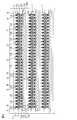
- FIG. 1 is a plan view of a circuit board for blood collection which is an embodiment of the circuit board for body fluid collection of the present invention.
- FIG. 2 is an enlarged plan view of the measurement unit of the circuit board for blood collection shown in FIG.
- FIG. 3 is an enlarged rear view of the measurement unit of the circuit board for blood collection shown in FIG.
- FIG. 4 is a sectional view taken along the line AA in FIG.
- FIG. 5 is a manufacturing process diagram for explaining an embodiment of a method for manufacturing a sampling circuit board according to the present invention, wherein (a) shows a step of preparing a metal substrate, and (b) shows a base insulating layer.
- FIG. 6 is a manufacturing process diagram for explaining the manufacturing method of the circuit board for collection following FIG. 5, and (e) shows a plurality of measurement units each provided with a puncture needle by externally processing a metal substrate.
- the step of forming the support portion, (f) shows the step of applying the drug to the electrode.
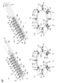
- FIG. 7 is a schematic perspective view for explaining one embodiment of a method for using the circuit board for collecting body fluid of the present invention, wherein (a) is a step of preparing a blood collection circuit board, and (b) is a first step.
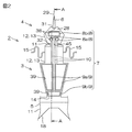
- FIG. 8 is a schematic perspective view of a blood glucose level measuring apparatus as an embodiment of the biosensor of the present invention, on which the blood collection circuit board shown in FIG. 7 is mounted, and (a) shows the drive shaft on the rear side.
- FIG. 9 is a side sectional view for explaining a method of using the blood sugar level measuring apparatus shown in FIG.
- A is a step of preparing a blood glucose level measuring device in which the drive shaft is arranged on the rear side
- (b) is a step of sliding the drive shaft to the front side and puncturing a finger with a puncture needle
- (c) is (D) shows a step of bringing the electrode into close contact with the puncture site by sliding the drive shaft to the rear side and pulling out the puncture needle.
- FIG. 10 is a schematic perspective view for explaining another embodiment of the method of using the circuit board for collecting bodily fluids of the present invention (a form in which each measurement unit extends radially inward with respect to the support portion) (in a plurality of measurement units).
- FIG. 11 is a schematic perspective view for explaining another embodiment of the method for using the circuit board for collecting bodily fluids of the present invention (a form in which each measurement unit extends radially inward with respect to the support portion) (in a plurality of measurement units).
- FIG. 12 is an enlarged plan view of a measurement unit (an embodiment in which the connector portion is substantially W-shaped in plan view) of the circuit board for blood collection which is another embodiment of the circuit board for body fluid collection of the present invention.
- FIG. 13 shows an enlarged plan view of a blood collection circuit board measurement unit (an embodiment in which the connector portion is linear in plan view), which is another embodiment of the body fluid collection circuit board of the present invention.
- FIG. 1 is a plan view of a blood collection circuit board which is an embodiment of a circuit board for body fluid collection of the present invention
- FIG. 2 is an enlarged plan view of a measurement unit of the circuit board for blood collection shown in FIG.
- FIG. 4 is an enlarged rear view of the blood collection circuit board measurement unit shown in FIG. 1,
- FIG. 4 is a cross-sectional view taken along line AA of FIG. 2, and
- FIGS. The manufacturing process figure for demonstrating one Embodiment is shown.
- this blood collection circuit board 1 collects blood by puncturing a skin such as a finger by a patient and measures the amount of glucose in the collected blood as a blood glucose level measuring device 19 (described later) as a biosensor.
- the circuit board 1 for blood collection is prepared as a type that can be measured a plurality of times and can be used repeatedly (continuous use).
- a plurality of blood collection circuit boards 1 are arranged in parallel in a longitudinal sheet-like frame portion 36 extending in the longitudinal direction (the vertical direction in FIG. 1 and corresponding to a puncture direction described later) along the longitudinal direction.
- the circuit boards 1 for blood collection are aligned and arranged at intervals in the longitudinal direction.
- Each blood collection circuit board 1 is supported by the frame portion 36 via the joint portion 37 and is formed to extend in a direction orthogonal to the longitudinal direction (hereinafter referred to as the width direction).
- the joint portion 37 is installed between the both ends in the width direction of the frame portion 36 and the both ends in the width direction of the blood collection circuit board 1 so as to be separable from each other.
- the circuit board for blood collection 1 is integrally provided with a support portion 5 extending along the width direction and a plurality (32) of measurement units 2 supported by the support portion 5 and extending along the longitudinal direction.
- the support portion 5 is formed in a substantially band shape in plan view extending in the width direction, and is formed with a gear 18 and a slit portion 16 as a fitting portion.
- the gear 18 is formed so as to be able to be fitted to a gear board 24 (FIG. 9), which will be described later, over almost the entire surface (excluding both ends in the width direction) of the other end surface in the longitudinal direction (end surface in the puncture direction) of the support portion 5. .
- the gear 18 is formed in a sawtooth shape in which crests and troughs are alternately arranged.
- the slit portions 16 are provided at both ends in the width direction of the support portion 5.
- the slit portion 16 is located at one end in the width direction of the support portion 5 (left end portion in FIG. 1) from the other end surface in the longitudinal direction of the support portion 5 to one side in the longitudinal direction and halfway in the longitudinal direction.
- the slit portion 16 is cut halfway in the longitudinal direction from one end surface in the longitudinal direction of the support portion 5 to the other side in the longitudinal direction at the other end portion in the width direction (right end portion in FIG. 1) of the support portion 5. It is formed in a slit shape. Thereby, the slit part 16 of the both ends of the width direction is mutually fitted when winding the support part 5 mentioned later.
- the measurement unit 2 is disposed so as to protrude from the support portion 5 toward one side in the longitudinal direction (downstream in the puncture direction and upper side in FIGS. 2 and 3). ing. Further, the measurement unit 2 is integrally provided with an upstream side portion 3 disposed on the upstream side in the puncturing direction and a downstream side portion 4 disposed on the downstream side of the upstream side portion 3 in the puncturing direction. As shown in FIG. 1, the upstream side portion 3 is arranged adjacent to the downstream end portion in the puncture direction of the support portion 5 in the puncture direction and is adjacent to the upstream side portion 3 of the measurement unit 2 adjacent in the width direction. Are arranged so as to face each other with a gap therebetween.
- the upstream side portion 3 is provided with a terminal 9 (described later), and is connected to a base portion having a substantially trapezoidal shape in plan view, which gradually becomes wider toward the downstream side in the puncture direction, and a connector portion 15 (described later).
- An intermediate portion having a substantially rectangular shape in plan view that protrudes toward the downstream side is integrally provided.
- the downstream end surface of the upstream side portion 3 in the puncture direction is formed in a substantially arc shape (or a substantially straight line shape) in plan view, whereby FIG.
- the blood collection circuit board 1 is formed in a substantially annular shape in which arcs are intermittently continuous when the support portion 5 is wound.
- the length in the width direction of the upstream side portion 3 (that is, the length in the width direction of the measurement unit 2) is, for example, 1 to 5 mm.
- the downstream side portion 4 is disposed so as to protrude toward the downstream side in the puncture direction from the substantially center in the width direction on the downstream side end face of the upstream side portion 3 in the puncture direction. Further, the downstream side portion 4 is formed so that the length in the width direction is shorter than that of the upstream side portion 3. Further, the downstream side portion 4 is formed of an electrode portion 28 formed in a substantially regular pentagonal shape in plan view and a puncture needle 6 disposed on the downstream side of the electrode portion 28 in the puncture direction.
- the measurement unit 2 includes one puncture needle 6 and a conductor pattern 7.
- the puncture needle 6 is provided for collecting blood by puncture.
- the puncture needle 6 is disposed adjacent to the downstream side portion 4 on the downstream side of the electrode portion 28 in the puncture direction, and is formed integrally with the electrode portion 28.
- the puncture needle 6 protrudes from the center in the width direction of the end portion on the downstream side in the puncture direction of the electrode portion 28 toward the downstream side in the puncture direction.
- the puncture needle 6 is formed in a substantially triangular shape (isosceles triangle shape) in a plan view in which the tip 29 (end on the downstream side in the puncture direction) has an acute angle along the puncture direction.
- the angle ⁇ 1 (see FIG. 3) of the tip 29 of the puncture needle 6 is, for example, 10 to 30 °, and preferably 15 to 25 °. If the angle ⁇ 1 of the tip 29 is less than 10 °, the skin may not be punctured due to insufficient strength. On the other hand, if the angle ⁇ 1 exceeds 30 °, it may be difficult to puncture.
- the length of the puncture needle 6 in the puncture direction is, for example, 0.5 to 10 mm, and the length of the puncture needle 6 in the width direction (the width of the upstream portion in the puncture direction) is, for example, 0.1 to 3 mm. . When the length and width of the puncture needle 6 are less than the above range, blood collection may be difficult. When the length and width of the puncture needle 6 exceeds the above range, In some cases, the puncture site may be damaged.
- the conductor pattern 7 includes three electrodes 8, three terminals 9, and three wirings 10.
- the three electrodes 8 are provided to come into contact with blood collected by puncturing with the puncture needle 6, and are arranged adjacent to each other in the width direction and the puncturing direction in the electrode portion 28. More specifically, of the three electrodes 8, the two electrodes 8 a are arranged to face each other with an interval in the width direction in the electrode portion 28.
- the two electrodes 8a are formed in a substantially circular shape in plan view.
- the remaining one electrode 8b is disposed to face the two electrodes 8b at the downstream side in the puncture direction at an interval in the electrode portion 28.
- the electrode 8b is formed in a substantially rectangular shape in plan view extending longer than between the two electrodes 8b in the width direction.
- the three electrodes 8 correspond to any one of a working electrode, a counter electrode, and a reference electrode.
- the diameters of the two electrodes 8a are, for example, 100 ⁇ m to 5 mm, and the length of one side of the one electrode 8b is, for example, 100 ⁇ m to 2.5 mm.
- the three electrodes 8 are arranged, for example, within 0.2 to 5 mm, preferably within 0.5 to 3 mm from the tip 29 of the puncture needle 6 in the puncture direction. If the distance between the tip 29 of the puncture needle 6 and the electrode 8 is too short, the electrode 8 pierces the skin together with the puncture needle 6, and the drug 30 (described later) applied to the surface of the electrode 8 diffuses into the body and is accurate. May interfere with measurement. On the other hand, if the distance between the tip 29 of the puncture needle 6 and the electrode 8 is too long, in order to introduce blood from the puncture needle 6 to the electrode 8, a configuration for utilizing suction or capillary action is required.
- the three terminals 9 are provided corresponding to the three electrodes 8, and are arranged at the base of the upstream side portion 3 in order to connect to a CPU 25 described later. More specifically, the two terminals 9a correspond to the two electrodes 8a, and are arranged to face each other with a gap in the width direction at the base portion of the upstream side portion 3. The remaining one terminal 9b corresponds to one electrode 8b, and is disposed opposite to the two terminals 9a with an interval on the upstream side in the puncture direction.
- the three terminals 9 are formed in a generally tapered shape in plan view that becomes wider as it goes downstream in the puncture direction. Specifically, the width direction inner end edges of the two terminals 9a facing each other are arranged in parallel along the puncture direction. Moreover, the width direction outer side edge in the two terminals 9a and the width direction both end edges of the remaining one terminal 9b are formed so as to be along a direction intersecting with each other in the puncture direction.
- the length of one side of the three terminals 9 is, for example, 0.5 to 5 mm.
- the three wirings 10 are provided over the upstream side portion 3 and the downstream side portion 4 and are arranged in parallel at intervals in the width direction.
- the three wires 10 are provided along the puncture direction so as to electrically connect each electrode 8 and each terminal 9 corresponding thereto.
- Each electrode 8, each terminal 9, and the wiring 10 which connects them are provided continuously and integrally.
- the length in the width direction of each wire 10 is, for example, 0.01 to 2 mm, and the length in the puncture direction of each wire 10 is, for example, 2 to 28 mm.
- Each measurement unit 2 includes a connector portion 15 as a reinforcing portion, a first bent portion 45, and a stopper portion 31.
- the connector portion 15 is arranged at a distance from the support portion 5 on the downstream side in the puncture direction, and connects the downstream side portions 4 of the measurement units 2 adjacent to each other.
- the connector part 15 is constructed between the intermediate parts of each downstream side part 4 so that it may be bent in a substantially S shape in plan view. Further, as shown in FIG. 7D, the connector portion 15 is formed in a substantially linear shape in plan view with the bent portion extending when the support portion 5 is wound.
- the first bent portion 45 is provided so as to be bendable on the upstream side in the puncture direction with respect to the tip 29 of the puncture needle 6. That is, the 1st bending part 45 is formed as a linear part extended along the width direction between the upstream part 3 and the downstream part 4 as shown in FIG.2 and FIG.3.
- the first bent portion 45 is formed as a constricted portion having a narrow width by an incision portion 32 that is thinly cut inward in the width direction in an adjacent portion where the upstream side portion 3 and the downstream side portion 4 are adjacent to each other.
- the stopper portion 31 is provided on the downstream side portion 4 at the downstream end portion in the puncture direction of the electrode portion 28 in order to prevent the puncture needle 6 from piercing the skin excessively deeply.
- the stopper portion 31 is formed in the electrode portion 28 as a portion in which the most downstream vertex in the puncture direction having a substantially regular pentagonal shape in plan view is recessed toward the upstream side in the puncture direction.
- the stopper portion 31 is provided in the electrode portion 28 so as to protrude from both outer sides in the width direction (upstream side in the oblique outer puncture direction).
- the distance between the downstream edge of the stopper 31 in the puncture direction and the tip 29 of the puncture needle 6 is, for example, 0.3 to 2 mm.
- the blood collection circuit board 1 has a second portion adjacent to the support portion 5 and the plurality of measurement units 2 (that is, corresponding to the boundary between the support portion 5 and the plurality of measurement units 2).
- a bent portion 14 is formed.
- the second bent portion 14 is provided so that the support portion 5 can be bent with respect to the plurality of measurement units 2.
- the blood collection circuit board 1 is laminated on the metal substrate 11, the base insulating layer 12 as an insulating layer laminated on the metal substrate 11, and the base insulating layer 12, as shown in FIG. And a cover insulating layer 13 provided on the base insulating layer 12 so as to cover the conductor pattern 7.
- the metal substrate 11 is made of a metal foil or the like, and is formed in a shape corresponding to the outer shape of the circuit board 1 for blood collection. That is, the metal substrate 11 is formed as one sheet in one blood collection circuit board 1.
- a metal material for forming the metal substrate 11 for example, nickel, chromium, iron, stainless steel (SUS304, SUS430, SUS316L) or the like is used.
- stainless steel is used from the viewpoint of having rigidity and capable of maintaining a bent shape to be described later when the support portion 5 is wound.
- the thickness of the metal substrate 11 is, for example, 10 to 300 ⁇ m, preferably 20 to 100 ⁇ m.
- the thickness is less than 10 ⁇ m, the skin may not be punctured (described later) due to insufficient strength. On the other hand, if the thickness exceeds 300 ⁇ m, pain may be felt at the time of puncturing, and the skin may be excessively damaged, or the first bent portion 45 and / or the second bent portion 14 may not be bent smoothly.
- the upstream side portion 3, the downstream side portion 4 (the electrode portion 28 and the puncture needle 6), and the support portion 5 are formed from the metal substrate 11. Since the puncture needle 6 is formed from the metal substrate 11 made of the above-described metal material, reliable puncture can be achieved. Moreover, since the gear 18 of the support part 5 is formed from the metal substrate 11 made of the above-described metal material, the blood sampling circuit board 1 can be reliably rotated.
- the base insulating layer 12 is formed on the surface of the metal substrate 11 corresponding to the upstream side portion 3 and the downstream side portion 4 in the upstream side portion 3 and the downstream side portion 4, and the surface of the metal substrate 11 in the support portion 5. Further, it is continuously formed in the width direction in the downstream side portion of the metal substrate 11 in the puncture direction, and the connector portion 15 is formed so as to correspond to the outer shape of the connector portion 15. Further, as shown in FIG. 2, the insulating base layer 12 is formed so as to expose the downstream end portion in the puncture direction of the metal substrate 11 in the upstream portion 3 in plan view. Further, as shown in FIG.
- the insulating base layer 12 has a peripheral end portion of the metal substrate 11, more specifically in the width direction of the metal substrate 11 in the downstream side portion 4 including the stopper portion 31 in a plan view. It is formed so as to bulge from the outer end and both ends in the puncture direction toward the outer side in the width direction and both sides in the puncture direction.
- the insulating material for forming the base insulating layer 12 for example, a synthetic resin such as a polyimide resin, a polycarbonate resin, a polyethylene resin, a polyethylene terephthalate resin, an epoxy resin, or a fluororesin is used. From the viewpoint of mechanical durability and chemical resistance, a polyimide resin is preferably used.
- the insulating base layer 12 has a thickness of, for example, 3 to 50 ⁇ m, preferably 5 to 25 ⁇ m. If the thickness is less than 3 ⁇ m, insulation defects such as pinholes may occur. On the other hand, when the thickness exceeds 50 ⁇ m, it may be difficult to perform cutting or outer shape processing.
- the conductor pattern 7 is formed on the surface of the base insulating layer 12, and is formed as a wiring circuit pattern including the above-described three electrodes 8, three terminals 9, and three wirings 10.
- a conductive material for forming the conductive pattern 7 for example, a metal material such as iron, nickel, chromium, copper, gold, silver, platinum, or an alloy thereof is used.
- the conductor material is appropriately selected from the viewpoint of adhesion to the insulating base layer 12 and the insulating cover layer 13 and ease of processing. Also, two or more kinds of conductor materials can be laminated.
- the thickness of the conductor pattern 7 is, for example, 5 to 50 ⁇ m, preferably 10 to 20 ⁇ m.
- the insulating cover layer 13 is provided on the surface of the insulating base layer 12 so as to cover each wiring 10. Further, as shown in FIGS. 2 to 4, the peripheral end portion of the insulating cover layer 13 is arranged so as to be located at the same position as the peripheral end portion of the insulating base layer 12 in plan view. Further, as shown in FIG. 4, the cover insulating layer 13 is formed with an electrode side opening 38 for exposing the electrode 8 and a terminal side opening 39 for exposing the terminal 9. Specifically, as shown in FIG. 2, the electrode-side opening 38 is formed to be slightly larger than the electrode 8 so as to surround the electrode 8 in plan view. The terminal side opening 39 is formed to be slightly larger than the terminal 9 so as to surround the terminal 9 in plan view. As an insulating material for forming the insulating cover layer 13, an insulating material similar to that of the above-described insulating base layer 12 is used. The insulating cover layer 13 has a thickness of 2 to 50 ⁇ m, for example.
- a stopper portion 31 is formed from the bulging portions of the base insulating layer 12 and the cover insulating layer 13 described above.
- the insulating material which forms the stopper part 31 is softer than a metal material, when the stopper part 31 prevents excessive puncture of the puncture needle 6, the damage of the skin which contact
- the connector portion 15 is formed from the base insulating layer 12 and the cover insulating layer 13. Therefore, in the formed circuit board 1 for blood collection, since the insulating material (synthetic resin) forming the base insulating layer 12 and the cover insulating layer 13 is softer than the metal material, the measurement unit 2 can be flexibly connected. At the same time, the measurement unit 2 can be flexibly connected while the bent portion of the connector portion 15 extends even when the circuit board 1 for blood collection described later is wound.
- the first bent portion 45 and the second bent portion 14 are formed from the metal substrate 11, the base insulating layer 12, and the cover insulating layer 13 described above.
- a method for manufacturing the circuit board 1 for blood collection will be described.
- a metal foil on which the metal substrate 11 is partitioned is prepared.
- a long sheet-like metal foil that is long in the longitudinal direction and can secure a large number of metal substrates 11 is prepared.
- each metal substrate 11 is subjected to outer shape processing in a later step, thereby forming a frame portion 36 and a plurality of blood collection circuit substrates 1.
- the base insulating layer 12 is formed on the surface of the metal substrate 11 as shown in FIG.
- the base insulating layer 12 is formed by, for example, applying a photosensitive synthetic resin varnish to the surface of the metal substrate 11 and curing it after photo processing, for example, laminating a synthetic resin film on the surface of the metal substrate 11, A method of laminating an etching resist having the same pattern as that of the base insulating layer 12 on the surface of the film, and then wet etching the film exposed from the etching resist, for example, a synthetic resin film previously mechanically punched on the surface of the metal substrate 11 For example, a method of laminating a synthetic resin film on the surface of the metal substrate 11 and then performing electric discharge machining or laser machining is used. From the viewpoint of processing accuracy, a method is preferably used in which a photosensitive synthetic resin varnish is applied to the surface of the metal substrate 11 and cured after photo processing.
- the conductor pattern 7 is formed by a known patterning method for forming a printed wiring, such as an additive method or a subtractive method. From the viewpoint of forming a fine pattern, an additive method is preferably used.
- a metal thin film 34 (broken line) is formed on the surface of the base insulating layer 12 by chemical vapor deposition or sputtering, a plating resist is formed on the surface of the metal thin film 34, and then the metal thin film exposed from the plating resist.
- a plating layer 35 is formed on the surface of 34 by electrolytic plating using the metal thin film 34 as a seed film.
- the conductor pattern 7 can also be formed only from the metal thin film 34 by chemical vapor deposition or sputtering.
- a different metal plating layer can be further formed on the surface of the electrode 8 and the surface of the terminal 9 by electrolytic plating or electroless plating.
- the thickness of the metal plating layer is preferably 0.05 to 10 ⁇ m.
- the insulating cover layer 13 is formed as shown in FIG.
- the insulating cover layer 13 is formed by a method similar to the method of forming the insulating base layer 12.
- a method is used in which a photosensitive synthetic resin varnish is applied to the surface of the insulating base layer 12 so as to cover the conductor pattern 7 and is cured after photo processing.
- the electrode side opening 38 and the terminal side opening 39 are formed in a pattern having the electrode side opening 38 and the terminal side opening 39 when the cover insulating layer 13 is formed in a pattern.
- the electrode side opening 38 and the terminal side opening 39 may be perforated by, for example, an electric discharge machining method, for example, a laser machining method.
- the metal substrate 11 is processed into an outer shape, and the puncture needle 6 and a plurality of measurement units 2 (upstream side portion 3, the puncture needle 6 and electrodes) arranged in parallel in the width direction.
- the downstream side portion 4 including the portion 28 (including the stopper portion 31), the support portion 5 in which the gear 18 and the slit portion 16 are formed, and the first bent portion 45 and the second bent portion 14 are formed simultaneously.
- the frame portion 36 and the joint portion 37 are simultaneously formed by the outer shape processing of the metal substrate 11.
- the circuit board for blood collection 1 is configured such that a plurality of measurement units 2 can be arranged radially by winding the support portion 5.
- the obtained blood collection circuit board 1 has, as shown in FIG. 6 (f), a drug 30, that is, an enzyme such as glucose oxidase, glucose dehydrogenase, or a mediator. , Potassium ferricyanide, ferrocene, benzoquinone and the like are applied alone or in combination.
- a drug 30 that is, an enzyme such as glucose oxidase, glucose dehydrogenase, or a mediator.
- Potassium ferricyanide, ferrocene, benzoquinone and the like are applied alone or in combination.
- medical agent 30 appropriate methods, such as an immersion method, a spray method, and an inkjet method, are used, for example.
- a different metal film is formed in advance to obtain a predetermined potential difference. It can also be granted. Specifically, after the gold plating layer is formed, silver or silver chloride is further applied to the surface of the gold plating layer. Further, the blood collection circuit board 1 is obtained by separating the frame portion 36 by cutting the joint portion 37.
- FIG. 7 is a schematic perspective view for explaining an embodiment of a method for using the circuit board for collecting body fluid of the present invention.
- a method for using the blood collection circuit board 1 will be described with reference to FIG.
- the joint portion 37 is cut as described above, and the blood collection circuit board 1 is separated from the frame portion 36, as shown in FIG.
- One blood collection circuit board 1 is prepared.
- blood collection circuit board 1 is arranged so that electrode 8 and terminal 9 face upward.
- the support portion 5 is bent upward with respect to the plurality of measurement units 2 with the second bent portion 14 as a boundary.
- the angle (bending angle) ⁇ 2 formed by the plurality of measurement units 2 and the support portion 5 is, for example, 45 to 135 °, preferably 60 to 120 °.
- the measurement unit 2 used for measurement cannot be reliably punctured, or the adjacent measurement unit 2 hinders puncture by the measurement unit 2 used for the measurement unit 2 (interference). ).
- the support unit 5 is wound and the plurality of measurement units 2 are arranged radially. Specifically, the support part 5 is wound so that each measurement unit 2 extends radially outward with respect to the support part 5. Further, as shown in FIG. 7D, the winding of the support portion 5 is held by fitting the slit portions 16 at both ends in the width direction of the support portion 5 together. Note that when the support portion 5 is wound, the connector portion 15 is formed in a substantially straight shape in plan view with the bent portion extended.
- FIG. 8 is a schematic perspective view of a blood glucose level measuring apparatus as an embodiment of the biosensor of the present invention on which the blood collection circuit board 1 shown in FIG. 7 is mounted.
- FIG. 9 is a blood glucose level measuring apparatus shown in FIG. Side sectional drawing for demonstrating the usage method of is shown. In FIG.
- the usage method of the blood-collecting circuit board 1 and the usage method of the blood glucose level measuring device 19 on which the blood-collecting circuit board 1 is mounted will be described.
- the blood collection circuit board 1 obtained as described above is used to measure blood glucose in order to measure the amount of glucose in the collected blood, as described above. It is mounted on the value measuring device 19 and used.
- the blood glucose level measuring device 19 includes a casing 41, a blood collection unit 42, a measurement unit 43 (not shown in FIG. 8) that measures glucose in the blood, and a display unit 44.
- the casing 41 is prepared to accommodate each member in the blood glucose level measuring device 19 and is formed in a box shape. Specifically, the casing 41 includes a blood collection unit 42 and a measurement unit 43, and a display unit 44 is provided on the surface thereof. Further, the casing 41 is formed with a front opening 33, an upper opening 22, and a bending guide 49.
- the front opening 33 is formed in the front wall of the casing 41 so as to be opened in a substantially rectangular shape in front view extending in the left-right direction, and when the blood collection circuit board 1 advances forward as described later. , A part (several) of the measurement units 2 are formed so as to be exposed.
- the upper opening 22 is a front side of the upper wall of the casing 41 and is formed as a long hole extending in the front-rear direction at the center in the left-right direction. Specifically, the drive shaft 21 described later slides in the front-rear direction. It is formed so that it can be inserted freely.
- the bending guide portion 49 is a central portion in the left-right direction of the front wall of the casing 41 and is provided at the upper edge of the upper opening 22 of the front wall, and is formed in a substantially flat plate shape. Further, the bending guide portion 49 is provided such that the front end edge is swingable in the vertical direction with the rear end edge as a fulcrum, and is always from the front wall of the casing 41 so as to shield the front side from the upper opening 22. It arrange
- the bending guide portion 49 is closed so as to block the front of the upper opening portion 22 when the blood collection circuit board 1 is punctured (see FIG. 9B), while the upper opening portion 22 is used for measuring the blood glucose level. Is exposed, and the foremost measurement unit 2 is exposed therefrom, and is opened so as not to contact the foremost measurement unit 2 (see FIG. 9D).
- the bending guide portion 49 is set so that the angle formed between the direction along the bending guide portion 49 and the front-rear direction is easy for the patient to use.
- the angle is not particularly limited and is adjusted to an appropriate angle. Specifically, for example, the angle is set to 15 to 60 °, preferably 20 to 45 °.
- the blood collection unit 42 includes a drive shaft 21 and a gear board 24, a guide unit 23, and a blood collection circuit board 1.
- the drive shaft 21 is disposed such that the axis extends in the vertical direction, and the lower end portion is formed integrally with the gear board 24.
- the gear board 24 is formed in a substantially disk shape, the drive shaft 21 is integrally inserted through the center thereof, and a plurality of drive grooves 40 extending radially from the center are formed on the upper surface.
- the gear 18 of the support portion 5 is fitted in the drive groove 40. That is, the gear board 24 is detachably attached to the gear 18 in a vertical direction and is relatively non-rotatably fitted, and the blood collection circuit board 1 is surrounded around the center of the gear board 24 (the axis of the drive shaft 21). It is provided to rotate in the direction.
- the guide portion 23 is provided at the peripheral end of the upper opening 22 of the upper wall of the casing 41. Specifically, the guide portion 23 is provided so as to guide the forward / backward movement of the drive shaft 21.
- the circuit board 1 for blood collection is provided so as to be able to advance and retract in the front-rear direction by the drive shaft 21 and to rotate in the circumferential direction by fitting with the gear board 24. Moreover, the circuit board 1 for blood collection is arrange
- the blood collection circuit board 1 is advanced, several front measurement units 2 are exposed from the front opening 33, and the puncture needle 6 of the front measurement unit 2 among these is the bending guide portion 49. It is provided so that it may contact with.
- the measurement unit 43 is electrically connected to the electrode 8 and includes a contact point 26 and a CPU 25.
- the contact 26 is provided so as to be slidable with respect to the terminal 9 so as to come into contact with the terminal 9 (see FIGS. 2 and 3) of the measurement unit 2 used for the measurement when measuring the circuit board 1 for blood collection. Further, the contact 26 is provided so that a voltage can be applied to the electrode 8 via the terminal 9 and a change in resistance value between the electrodes 8 at the time of voltage application can be detected.
- the CPU 25 is electrically connected to the contact point 26 via the signal wiring 48 and is connected to the display unit 44. Further, the CPU 25 calculates the amount of glucose as a blood glucose level based on the change in the resistance value between the electrodes 8 detected at the contact 26 during measurement by the blood collection circuit board 1.
- the display unit 44 is provided on the rear side of the upper wall of the casing 41, and includes, for example, an LED, and displays a blood sugar level measured by the CPU 25.
- the drive shaft 21 is slid rearward to prepare the blood glucose level measuring device 19.
- the patient's own finger or the like is placed below the bending guide portion 49.
- the drive shaft 21 is slid in the rear side in advance, it is not necessary to slide the drive shaft 21.
- all the measurement units 2 of the blood collection circuit board 1 are accommodated in the casing 41 without being exposed from the front opening 33.
- the patient himself / herself moves the drive shaft 21 to the front side to expose the puncture needle 6 from the front side opening 33.
- the puncture needle 6 is punctured.
- the blood collection circuit board 1 is advanced to the front side, and among the measurement units 2, several measurement units 2 are exposed from the front opening 33, and the foremost measurement unit 2 is bent to the bending guide portion 49.
- the downstream side portion 4 is bent obliquely downward with respect to the upstream side portion 3 with the first bent portion 45 as a boundary.
- the puncture needle 6 of the bent downstream side part 4 is punctured to a finger
- the bending guide portion 49 Since the bending guide portion 49 is disposed at the predetermined angle as viewed from the side, the bending angle at the first bending portion 45 is, for example, 15 to 60 °, preferably 20 to 45 °. It becomes. At this time, the puncture of the puncture needle 6 is restricted when the stopper portion 31 comes into contact with the skin. Thereby, the puncture depth of the puncture needle 6 becomes, for example, 0.5 to 1.5 mm.
- the drive shaft 21 is slid rearward, and the puncture needle 6 is pulled out from the finger or the like to cause a slight bleeding from the puncture site.
- the measurement unit 2 bent by the bending guide part 49 is separated from the bending guide part 49, so that the bending angle is relaxed.
- the bending angle at the first bending portion 45 is, for example, 15 to 60 °, preferably 15 to 40 °.
- microbleeding at the puncture site can be promoted by pressing (squeezing) the vicinity of the puncture site, if necessary.
- the bending guide portion 49 is opened by swinging the front end portion upward, and the drive shaft 21 is slid again to the front side.
- the electrode 8 of the foremost measurement unit 2 is brought close to and in contact with the puncture site.
- the blood collection circuit board 1 is rotated by rotating the drive shaft 21 and the gear board 24 in the circumferential direction around the center of the gear board 24, and the measurement unit after use.
- An unused measurement unit 2 arranged adjacent to the upstream side in the rotational direction with respect to 2 is arranged on the forefront side.
- each of the steps shown in FIGS. 9A to 9D is performed a plurality of times, and the blood glucose level is measured a plurality of times.
- the circuit board 1 for blood collection and the blood glucose level measuring device 19 having the blood collection board blood is bleed by puncturing with the puncture needle 6 and the bleed blood is simply brought into contact with the electrode 8 of the measurement unit 2.
- the blood glucose level can be easily measured by the CPU 25 electrically connected to the electrode 8.
- the blood collection circuit board 1 and the blood glucose level measuring device 19 can easily measure the blood glucose level with a simple configuration.
- the blood glucose level can be measured a plurality of times by a plurality of measurement units 2 provided on one circuit board 1 for blood collection. Furthermore, in this circuit board for blood collection 1, if the plurality of measurement units 2 are arranged radially by winding the support portion 5, the circuit board for blood collection 1 is circulated after the use of one measurement unit 2. By rotating in the direction, the used measurement unit 2 and the unused measurement unit 2 adjacent to the measurement unit 2 on the upstream side in the rotation direction can be exchanged. Therefore, the measurement unit 2 can be easily exchanged for every measurement.
- the plurality of measurement units 2 arranged in parallel in the width direction and the support portion 5 are formed by the outer shape processing of the metal substrate 11. Therefore, the installation space of the blood collection circuit board 1 arranged in parallel to the frame portion 36 can be made compact, space saving can be achieved, the yield of the blood collection circuit board 1 can be improved, and the cost of the production efficiency can be improved. Reduction can be achieved.
- the second bent portion 14 that is a boundary between the plurality of measurement units 2 and the support portion 5 is bent, and the bent support portion 5 is wound.
- a plurality of measurement units 2 can be arranged radially. Therefore, a plurality of measurement units 2 can be arranged radially by a simple process.
- unnecessary contact and damage by the measuring unit 2 adjacent to the measuring unit 2 can be prevented, and only the measuring unit 2 used for the measurement is used. Can be used.
- the circuit board 1 for blood collection reliable puncture and measurement can be achieved by the plurality of measurement units 2 arranged on the outer side in the radial direction of the wound support portion 5. Furthermore, according to the circuit board 1 for blood collection, since the measurement units 2 are connected by the connector portion 15 even when the plurality of measurement units 2 are arranged radially, the plurality of measurement units 2 can be securely connected. Can be supported. Therefore, reliable puncture and measurement of the measurement unit 2 can be achieved.
- the slit part 16 of the width direction one end part and the slit part 16 of the other end part in the support part 5 are fitted.
- the winding of the support part 5 can be hold
- FIG. 7B solid line portion
- the support portion 5 is bent upward with respect to the plurality of measurement units 2 where the electrodes 8 and the terminals 9 are exposed upward. For example, as shown by a broken line in FIG. 7B, the plurality of measurement units 2 can be bent downward.
- FIG. 10 and 11 are schematic perspective views for explaining another embodiment of the method for using the circuit board for collecting body fluid of the present invention (a form in which each measurement unit extends radially inward with respect to the support portion).
- FIG. 10 shows an aspect in which the support portion is bent upward with respect to the plurality of measurement units
- FIG. 11 shows an aspect in which the support portion is bent downward with respect to the plurality of measurement units.
- symbol is attached
- the support portion 5 is wound so that each measurement unit 2 extends radially outward with respect to the support portion 5.
- the direction in which the unit 2 extends with respect to the support portion 5 is not limited to this.
- the winding is performed so that each measurement unit 2 extends radially inward with respect to the support portion 5. You can also turn.
- FIG. 12 and 13 are enlarged plan views of a measurement unit of a circuit board for collecting blood, which is another embodiment of the circuit board for collecting body fluid of the present invention, and FIG. One aspect, FIG. 13, shows an aspect in which the connector portion is linear in plan view.
- the connector portion 15 is formed in a substantially S shape in plan view, but the shape thereof is not particularly limited and can be formed in an appropriate shape, for example, as shown in FIG. Further, it can be formed in a substantially W shape in a plan view, and can also be formed in a straight line shape in a plan view along the width direction as shown in FIG.
- the connector unit 15 is preferably substantially S-shaped in plan view (FIGS. 2 and 3). ) Or a substantially W shape (FIG. 12) in plan view.
- the length of the connector part 15 between each measurement unit 2 before winding is 0.5 mm or more, for example, Preferably, it is 2 mm or more, and usually is 10 mm or less.
- the connector portion 15 when the connector portion 15 is formed in a straight line shape in plan view, preferably, the support portions 5 are arranged so that each measurement unit 2 extends radially inward with respect to the support portion 5. Wrap it. On the contrary, if the support part 5 is wound so that each measurement unit 2 extends radially outward with respect to the support part 5, the connector part 15 may be cut.
- the connector portion 15 is formed from the base insulating layer 12 and the cover insulating layer 13, but the layer configuration of the connector portion 15 is not limited to this.
- the connector portion 15 can be formed of only one of the base insulating layer 12 and the cover insulating layer 13.
- 32 measurement units 2 are provided on the blood collection circuit board 1, but the number is not particularly limited, and is appropriately selected according to the size of the casing 41, for example, 10 or more, preferably 20 or more, and usually 70 or less can be provided.
- the size of the circuit board for blood collection 1 is appropriately selected according to the size of the casing 41, the number of measurement units 2, and the like, and is not particularly limited. (Length between the upstream end of the support portion 5 in the puncture direction and the tip 29 of the puncture needle 6) is 3 to 50 mm, preferably 5 to 15 mm.
- the electrode 8 becomes excessively small, and it may be difficult to form the electrode 8 or apply the medicine 30.
- the length of the puncture direction of the blood collection circuit board 1 exceeds the above range, the yield of the blood collection circuit board 1 may be reduced, leading to an increase in cost.
- the length in the width direction of the circuit board for blood collection 1 (or the length between both ends in the width direction of the support portion 5) is, for example, 50 to 300 mm, preferably 80 to 150 mm. If the length in the width direction of the circuit board for blood collection 1 is less than the above range, the number of measurement units 2 may be excessively reduced. On the other hand, if the length in the width direction of the blood collection circuit board 1 exceeds the above range, the yield of the blood collection circuit board 1 may be reduced, leading to an increase in cost.
- the gear 18 is provided on almost the entire end face in the puncture direction upstream side of the support portion 5.
- the end face in the puncture direction upstream side of the support portion 5 is provided.
- the remaining surface can be formed into a flat surface (a shape without unevenness).
- the drive groove 40 (see FIG. 8) of the gear board 24 is formed in a shape corresponding to the gear 18 described above.
- the gear 18 can be formed so that the key can be fitted into the drive groove 40 of the gear board 24 formed in a key shape.
- the circuit board for collecting body fluid and the biosensor including the circuit board for collecting body fluid of the present invention are exemplified as the circuit board for blood collection 1 and the blood glucose level measuring device 19 including the circuit board for blood collection 1.
- the body fluid collected by the puncture of the puncture needle of the body fluid collection circuit board is described as blood.
- the body fluid is not particularly limited as long as it is in vivo, and examples thereof include extracellular fluid and intracellular fluid.
- extracellular fluid the aforementioned blood is removed, and examples thereof include plasma, interstitial fluid, lymph fluid, moisture in dense connective tissue, bone and cartilage, and cell permeate.
- the specific component of the above-mentioned body fluid can be measured with a circuit board for collecting body fluid and a biosensor including this circuit board for collecting body fluid.
- Example 1 Manufacture of circuit board for blood collection shown in FIG. 1
- a long sheet-like metal foil having a thickness of 50 ⁇ m and a width of 300 mm was prepared (see FIG. 5A).
- a varnish of a photosensitive polyimide resin precursor photosensitive polyamic acid resin
- the base insulating layer having a thickness of 10 ⁇ m was formed in the above-described pattern by heating to 400 ° C. in a nitrogen atmosphere (see FIG. 5B).
- a metal thin film composed of a chromium thin film and a copper thin film was sequentially formed on the surface of the base insulating layer by sputtering. Thereafter, a dry film resist was laminated on the surface of the metal thin film, and was exposed and developed to form a plating resist as a pattern. Then, on the surface of the metal thin film exposed from the plating resist, a plating layer made of copper was formed by electrolytic copper plating using the metal thin film as a seed film, and a conductor pattern including electrodes, terminals, and wirings was formed (FIG. 5 ( c)). Thereafter, the plating resist and the metal thin film where the plating resist was formed were removed by etching.
- the thickness of the conductor pattern is 12 ⁇ m, the diameter of the two electrodes (8a) is 0.3 mm, the length of the long side of one electrode (8b) is 1.0 mm, and the length of the short side is 0.6 mm. It was.
- the length of one side of the two terminals (9a) was 3 mm, and the length of one side of the one terminal (9b) was 1 mm.
- the width of the wiring is 100 ⁇ m, the length of the wiring connecting the two electrodes 8a and the two terminals 9a is 3 mm, and the length of the wiring connecting the one electrode 8b and the one terminal 9b is 7 mm. It was.
- a varnish of a photosensitive polyimide resin precursor (photosensitive polyamic acid resin) is applied to the surface of the base insulating layer so as to cover the conductor pattern, and after heating and drying to form a film, exposure and development are performed.
- a film was formed into a pattern.
- it heated at 400 degreeC in nitrogen atmosphere, and formed the 5-micrometer-thick cover insulating layer (refer FIG.5 (d)).
- the insulating cover layer was formed such that the electrode and the terminal were exposed and the wiring was covered by forming the electrode side opening and the terminal side opening.
- an electrolytic nickel plating layer (thickness 0.5 ⁇ m) and an electrolytic gold plating layer (thickness 2.5 ⁇ m) were sequentially formed on the surfaces of the electrodes and terminals.
- a dry film resist was laminated on the surface of the metal substrate, and was exposed and developed to form an etching resist as a pattern.
- a metal substrate exposed from the etching resist is etched by wet etching using ferric chloride as an etchant, and a plurality of measurement units arranged in parallel in the width direction, including a puncture needle, and a gear and a slit portion are provided
- the outer shape was processed as the above-described pattern of the formed support portion, the first bent portion, and the second bent portion (see FIG. 6E).
- the frame part and the joint part were simultaneously formed by the external shape processing of this metal substrate.
- the length from the tip of the puncture needle to one electrode (8b) (the electrode closest to the tip) is 1.8 mm, the angle of the tip of the puncture needle is 20 °, and the width of the bulging portion of the stopper is 0.
- the distance between the downstream edge of the stopper portion in the puncture direction and the tip of the puncture needle was 1.4 mm.
- the length in the width direction of the circuit board for blood collection was 2.7 mm, and the length in the puncture (longitudinal) direction was 10 mm.
- circuit board for blood collection a drug containing glucose oxidase and a potassium ferricyanide solution was applied to the electrodes in each measurement unit by inkjet (see FIG. 6F). Thereafter, by cutting the joint portion, the circuit board for blood collection is separated from the frame portion, and the circuit board for blood collection is arranged so that the electrodes and terminals are exposed upward (see FIG. 7A). Then, the support part was bent 90 ° upward with respect to the plurality of measurement units with the second bent part as a boundary (see FIG. 7B).
- each measurement unit extends radially outward with respect to the support portion, and the slit portions at both ends in the width direction of the support portion are fitted to each other, thereby winding the support portion.
- a plurality of measurement units were arranged radially (see FIGS. 7C and 7D).
- the wound circuit board for blood collection was mounted in a casing provided with a display unit together with a drive shaft, a gear board, and a guide (see FIGS. 8 and 9).
- the drive groove of the gear board formed integrally with the drive shaft was fitted into the gear, and the drive shaft was slidably inserted into the guide portion.
- the blood glucose level measuring apparatus described above was prepared, and then the patient's own finger was placed below the bending guide part (see FIGS. 8A and 9A).
- the drive shaft was slid rearward, and the puncture needle was pulled out from the finger to cause a slight bleeding from the puncture site (see FIG. 9C).
- the measurement unit bent at the bent portion is separated from the bent guide portion, and the bent angle at the bent portion becomes 35 °, and the bent angle is relaxed.
- the bending guide part is opened, and the drive shaft is slid forward again to expose the electrode of the foremost measurement unit from the front opening, and the electrode is brought into close contact with the puncture site (FIG. 9). (See (d)).
- the circuit board for collecting body fluid of the present invention, a method for producing and using the same, and a biosensor provided with the circuit board are suitably used in the field of measuring blood glucose levels in blood, for example.
Abstract
体液採取用回路基板は、穿刺針と、穿刺針の穿刺により採取される体液と接触させるための電極とを備え、一定方向に並列配置される複数の測定ユニットと、並列方向に沿って延び、複数の測定ユニットを支持する支持部とを備え、支持部を巻回することにより、複数の測定ユニットを放射状に配置可能とする。
Description
本発明は、体液採取用回路基板、体液採取用回路基板の製造方法、体液採取用回路基板の使用方法、および、体液採取用回路基板を備えるバイオセンサに関する。
糖尿病には、インシュリン依存性(I型)とインシュリン非依存性(II型)とがあり、前者は、定期的なインシュリンの投与が必要となる。そのため、前者では、患者が自ら採血し、自ら血糖値を測定し、その血糖値に応じた投与量でインシュリンを自ら投与する処置方法が採用されている。
専ら、そのような患者のために、患者自身が、個人的に採血し、血糖値を測定することのできる血糖値測定装置が知られている。
専ら、そのような患者のために、患者自身が、個人的に採血し、血糖値を測定することのできる血糖値測定装置が知られている。
例えば、電極が挿入され、本体中央に設けられる反応区域と、本体中央から外方に突出する穿刺針と、電極と穿刺針とを連通する毛管路とを備える流体収集装置が提案されている(例えば、下記特許文献1参照。)。
特開2004-493号公報
上記特許文献1に記載される流体収集装置では、穿刺針と反応区域とが本体に一体的に形成されているので、測定準備が簡便である。しかし、この流体収集装置では、反応区域とは別部材である電極を、反応区域へ挿入して、血液成分を測定する。そのため、血液の検知精度が不安定となり、精度よく測定できないという不具合がある。
また、I型の糖尿病においては、症状によっては、患者が、1日に複数回、具体的には、食前毎あるいは食後毎に、血糖値を測定する必要がある。
また、I型の糖尿病においては、症状によっては、患者が、1日に複数回、具体的には、食前毎あるいは食後毎に、血糖値を測定する必要がある。
一方、上記特許文献1に記載される流体収集装置では、1個の装置につき、1本の穿刺針しか備えられていないので、穿刺針の繰り返しの使用を避ける必要上、1回の測定ができるのみである。
そのため、上記した流体収集装置で、上記したように複数回測定する場合には、使用済みの流体収集装置を廃棄し、その後、新たな流体収集装置を準備する必要がある。そのため、かかる流体収集装置では、上記した測定準備が繁雑になり、ランニングコストの上昇が不可避となる。
そのため、上記した流体収集装置で、上記したように複数回測定する場合には、使用済みの流体収集装置を廃棄し、その後、新たな流体収集装置を準備する必要がある。そのため、かかる流体収集装置では、上記した測定準備が繁雑になり、ランニングコストの上昇が不可避となる。
本発明の目的は、簡易な構成により、体液の成分を精度よく測定することができ、しかも、1個の体液採取用回路基板で、複数回、簡便に測定することのできる、体液採取用回路基板、その製造方法、その使用方法、および、その体液採取用回路基板を備えるバイオセンサを提供することにある。
上記の目的を達成するため、本発明の体液採取用回路基板は、穿刺針と、前記穿刺針の穿刺により採取される体液と接触させるための電極とを備え、一定方向に並列配置される複数の測定ユニットと、前記並列方向に沿って延び、複数の前記測定ユニットを支持する支持部とを備え、前記支持部を巻回することにより、複数の前記測定ユニットを放射状に配置可能とすることを特徴としている。
この体液採取用回路基板は、穿刺針と電極とを備える測定ユニットを備えている。そのため、穿刺針の穿刺により体液を流出させて、流出させた体液を、測定ユニットの電極と簡便に接触させることができる。その結果、この体液採取用回路基板によれば、簡易な構成により、体液の成分を簡便に測定することができる。
しかも、この体液採取用回路基板では、1個の体液採取用回路基板に設けられる複数の測定ユニットによって、体液の成分を、複数回測定することができる。
しかも、この体液採取用回路基板では、1個の体液採取用回路基板に設けられる複数の測定ユニットによって、体液の成分を、複数回測定することができる。
さらに、この体液採取用回路基板では、支持部を巻回することにより、複数の測定ユニットを放射状に配置すれば、1個の測定ユニットの使用後には、体液採取用回路基板を周方向に回転させることにより、使用後の測定ユニットとその測定ユニットに対して回転方向上流側に隣接する未使用の測定ユニットとを交換することができる。そのため、複数回の測定毎に、測定ユニットを簡便に交換することができる。
また、本発明の体液採取用回路基板では、各前記測定ユニットは、複数の前記測定ユニットを放射状に配置するときには、前記支持部に対して外側に延びていることが好適である。
この体液採取用回路基板によれば、巻回された支持部の外側において、複数の測定ユニットによって、確実な穿刺および測定を達成することができる。
この体液採取用回路基板によれば、巻回された支持部の外側において、複数の測定ユニットによって、確実な穿刺および測定を達成することができる。
また、本発明の体液採取用回路基板では、各前記測定ユニットは、複数の前記測定ユニットを放射状に配置するときには、前記支持部に対して内側に延びていることが好適である。
この体液採取用回路基板によれば、巻回された支持部の内側において、複数の測定ユニットによって、確実な穿刺および測定を達成することができる。
この体液採取用回路基板によれば、巻回された支持部の内側において、複数の測定ユニットによって、確実な穿刺および測定を達成することができる。
また、本発明の体液採取用回路基板では、さらに、前記支持部と間隔を隔てて配置され、各前記測定ユニット間において、互いに隣接する各前記測定ユニットを連結する補強部を備えていることが好適である。
この体液採取用回路基板によれば、複数の測定ユニットを放射状に配置しても、補強部によって、各測定ユニットが連結されているので、複数の測定ユニットを確実に支持することができる。そのため、測定ユニットの確実な穿刺および測定を達成することができる。
この体液採取用回路基板によれば、複数の測定ユニットを放射状に配置しても、補強部によって、各測定ユニットが連結されているので、複数の測定ユニットを確実に支持することができる。そのため、測定ユニットの確実な穿刺および測定を達成することができる。
また、本発明の体液採取用回路基板では、さらに、前記支持部における前記並列方向一端部および他端部に、前記支持部の巻回を保持するための嵌合部を備えていることが好適である。
この体液採取用回路基板によれば、支持部を巻回するときに、支持部における並列方向一端部の嵌合部と、他端部の嵌合部とを嵌合させることにより、支持部の巻回を保持することができる。そのため、複数の測定ユニットを確実に放射状に配置することができる。
この体液採取用回路基板によれば、支持部を巻回するときに、支持部における並列方向一端部の嵌合部と、他端部の嵌合部とを嵌合させることにより、支持部の巻回を保持することができる。そのため、複数の測定ユニットを確実に放射状に配置することができる。
体液採取用回路基板は、穿刺針と、前記穿刺針の穿刺により採取される体液と接触させるための電極とを備え、一定方向に並列配置される複数の測定ユニットと、前記並列方向に沿って延び、複数の前記測定ユニットを支持する支持部とを備え、複数の前記測定ユニットと前記支持部との境界が折り曲げられ、前記支持部が巻回されることにより、複数の前記測定ユニットが放射状に配置されていることを特徴としている。
この体液採取用回路基板は、穿刺針と電極とを備える測定ユニットを備えている。そのため、穿刺針の穿刺により体液を流出させて、流出させた体液を、測定ユニットの電極と簡便に接触させることができる。その結果、この体液採取用回路基板によれば、簡易な構成により、体液の成分を簡便に測定することができる。
しかも、この体液採取用回路基板では、1個の体液採取用回路基板に設けられる複数の測定ユニットによって、体液の成分を、複数回測定することができる。
しかも、この体液採取用回路基板では、1個の体液採取用回路基板に設けられる複数の測定ユニットによって、体液の成分を、複数回測定することができる。
さらに、この体液採取用回路基板では、支持部が巻回されることにより、複数の測定ユニットが放射状に配置されているので、1個の測定ユニットの使用後には、体液採取用回路基板を周方向に回転させることにより、使用後の測定ユニットとその測定ユニットに対して回転方向上流側に隣接する未使用の測定ユニットとを交換することができる。そのため、複数回の測定毎に、測定ユニットを簡便に交換することができる。
また、本発明の体液採取用回路基板では、各前記測定ユニットは、前記支持部に対して外側に延びていることが好適である。
この体液採取用回路基板によれば、巻回された支持部の外側において、複数の測定ユニットによって、確実な穿刺および測定を達成することができる。
また、本発明の体液採取用回路基板では、各前記測定ユニットは、前記支持部に対して内側に延びていることが好適である。
この体液採取用回路基板によれば、巻回された支持部の外側において、複数の測定ユニットによって、確実な穿刺および測定を達成することができる。
また、本発明の体液採取用回路基板では、各前記測定ユニットは、前記支持部に対して内側に延びていることが好適である。
この体液採取用回路基板によれば、巻回された支持部の内側において、複数の測定ユニットによって、確実な穿刺および測定を達成することができる。
また、本発明のバイオセンサは、上記した体液採取用回路基板と、前記電極に電気的に接続され、前記体液の成分を測定する測定部とを備えることを特徴としている。
このバイオセンサによれば、上記した体液採取用回路基板により流出させた体液を、電極と接触させて、この電極と電気的に接続される測定部によって、体液の成分を簡便に測定することができる。
また、本発明のバイオセンサは、上記した体液採取用回路基板と、前記電極に電気的に接続され、前記体液の成分を測定する測定部とを備えることを特徴としている。
このバイオセンサによれば、上記した体液採取用回路基板により流出させた体液を、電極と接触させて、この電極と電気的に接続される測定部によって、体液の成分を簡便に測定することができる。
また、本発明の体液採取用回路基板の製造方法は、金属基板を用意する工程、前記金属基板の上に、絶縁層を形成する工程、前記絶縁層の上に、体液と接触させるための電極を形成する工程、および、前記金属基板を外形加工することにより、穿刺により体液を採取するための穿刺針と、前記並列方向に沿って延び、前記穿刺針および前記電極を備え、一定方向に並列配置される複数の測定ユニットと、前記並列方向に沿って延び、複数の前記測定ユニットを支持する支持部とを形成する工程を備え、前記測定ユニットと前記支持部とを形成する工程において、前記支持部を巻回することにより、複数の前記測定ユニットを放射状に配置できるように、前記金属基板を外形加工することを特徴としている。
この体液採取用回路基板の製造方法によれば、支持部を巻回することにより、複数の測定ユニットを放射状に配置することができる。そのため、体液採取用回路基板をそのように配置すれば、1個の測定ユニットの使用後には、体液採取用回路基板を周方向に回転させることにより、使用後の測定ユニットとその測定ユニットに対して回転方向上流側に隣接する未使用の測定ユニットとを交換することができる。そのため、複数回の測定毎に、測定ユニットを簡便に交換することができる。
しかも、この体液採取用回路基板の製造方法によれば、金属基板の外形加工により、複数の測定ユニットと支持部とを、一定方向に並列配置する。そのため、体液採取用回路基板の歩留りを向上させることができ、生産効率の向上によるコストの低減を図ることができる。
また、本発明の体液採取用回路基板の使用方法は、上記した体液採取用回路基板の製造方法により製造される体液採取用回路基板が用いられ、複数の前記測定ユニットと前記支持部との境界を折り曲げる工程、および、前記支持部を巻回することにより、複数の前記測定ユニットを放射状に配置する工程を備えていることを特徴としている。
また、本発明の体液採取用回路基板の使用方法は、上記した体液採取用回路基板の製造方法により製造される体液採取用回路基板が用いられ、複数の前記測定ユニットと前記支持部との境界を折り曲げる工程、および、前記支持部を巻回することにより、複数の前記測定ユニットを放射状に配置する工程を備えていることを特徴としている。
この体液採取用回路基板の使用方法によれば、複数の測定ユニットと支持部との境界を折り曲げ、折り曲げられた支持部を巻回することにより、複数の測定ユニットを放射状に配置することができる。そのため、簡易な工程によって、複数の測定ユニットを放射状に配置することができる。
本発明の体液採取用回路基板によれば、簡易な構成により、体液の成分を簡便に測定しながら、1個の体液採取用回路基板で、複数設けられる測定ユニットによって、体液の成分を、複数回測定することができる。さらに、複数回の測定毎に、測定ユニットを簡便に交換することができる。
また、本発明のバイオセンサによれば、体液の成分を簡便に測定することができる。
また、本発明のバイオセンサによれば、体液の成分を簡便に測定することができる。
また、本発明の体液採取用回路基板の製造方法によれば、複数回の測定毎に、測定ユニットを簡便に交換することができながら、体液採取用回路基板の歩留りを向上させて、コストの低減を図ることができる。
また、体液採取用回路基板の使用方法によれば、簡易な工程によって、複数の測定ユニットを放射状に配置することができる。
また、体液採取用回路基板の使用方法によれば、簡易な工程によって、複数の測定ユニットを放射状に配置することができる。
図1は、本発明の体液採取用回路基板の一実施形態である採血用回路基板の平面図、図2は、図1に示す採血用回路基板の測定ユニットの拡大平面図、図3は、図1に示す採血用回路基板の測定ユニットの拡大背面図、図4は、図2のA-A線に沿う断面図、図5および図6は、本発明の採取用回路基板の製造方法の一実施形態を説明するための製造工程図を示す。
図1において、この採血用回路基板1は、患者が指などの皮膚を穿刺して採血し、採血した血液中のグルコース量を測定するために、後述するバイオセンサとしての血糖値測定装置19(図8および図9参照)に実装されて用いられる。この採血用回路基板1は、複数回測定できる、繰り返し使用可能(連続使用可能)タイプとして用意されている。
採血用回路基板1は、例えば、長手方向(図1において上下方向であって、後述する穿刺方向に相当。)に延びる長尺シート状の枠部36に、その長手方向に沿って複数並列配置されている。具体的には、採血用回路基板1は、長手方向において間隔を隔てて整列配置されている。また、各採血用回路基板1は、ジョイント部37を介して枠部36に支持され、長手方向に直交する方向(以下、幅方向という。)に延びるように形成されている。
採血用回路基板1は、例えば、長手方向(図1において上下方向であって、後述する穿刺方向に相当。)に延びる長尺シート状の枠部36に、その長手方向に沿って複数並列配置されている。具体的には、採血用回路基板1は、長手方向において間隔を隔てて整列配置されている。また、各採血用回路基板1は、ジョイント部37を介して枠部36に支持され、長手方向に直交する方向(以下、幅方向という。)に延びるように形成されている。
ジョイント部37は、枠部36の幅方向両端部と、採血用回路基板1の幅方向両端部との間において、これらを分離可能に、それぞれ架設されている。
採血用回路基板1は、幅方向に沿って延びる支持部5と、支持部5に支持され、長手方向に沿って延びる複数(32個)の測定ユニット2とを一体的に備えている。
支持部5は、幅方向に延びる平面視略帯状に形成され、ギヤ18および嵌合部としてのスリット部16が形成されている。
採血用回路基板1は、幅方向に沿って延びる支持部5と、支持部5に支持され、長手方向に沿って延びる複数(32個)の測定ユニット2とを一体的に備えている。
支持部5は、幅方向に延びる平面視略帯状に形成され、ギヤ18および嵌合部としてのスリット部16が形成されている。
ギヤ18は、支持部5の長手方向他端面(穿刺方向上流側端面)のほぼ全面(幅方向両端部を除く)にわたって、後述するギヤ盤24(図9)に嵌合可能に形成されている。具体的には、ギヤ18は、山部および谷部が交互に配列される鋸歯形状に形成されている。
スリット部16は、支持部5における幅方向両端部に設けられている。具体的には、スリット部16は、支持部5における幅方向一端部(図1においては左端部)においては、支持部5の長手方向他端面から長手方向一側に向かって、長手方向途中まで切り込まれるスリット状に形成されている。また、スリット部16は、支持部5における幅方向他端部(図1においては右端部)においては、支持部5の長手方向一端面から長手方向他側に向かって、長手方向途中まで切り込まれるスリット状に形成されている。これにより、幅方向両端部のスリット部16は、後述する支持部5を巻回するときに、互いに嵌合する。
スリット部16は、支持部5における幅方向両端部に設けられている。具体的には、スリット部16は、支持部5における幅方向一端部(図1においては左端部)においては、支持部5の長手方向他端面から長手方向一側に向かって、長手方向途中まで切り込まれるスリット状に形成されている。また、スリット部16は、支持部5における幅方向他端部(図1においては右端部)においては、支持部5の長手方向一端面から長手方向他側に向かって、長手方向途中まで切り込まれるスリット状に形成されている。これにより、幅方向両端部のスリット部16は、後述する支持部5を巻回するときに、互いに嵌合する。
測定ユニット2は、図2および図3に示すように、支持部5から、長手方向一側(穿刺方向下流側であって、図2および図3において上側)に向かって突出するように配置されている。また、測定ユニット2は、穿刺方向上流側に配置される上流側部3と、上流側部3の穿刺方向下流側に配置される下流側部4とを一体的に備えている。
上流側部3は、図1に示すように、支持部5の穿刺方向下流側端部と穿刺方向において連続して隣接配置され、幅方向に隣接する測定ユニット2の上流側部3と幅方向に間隔を隔てて対向配置されるように形成されている。上流側部3は、端子9(後述)が設けられ、穿刺方向下流側に向かって次第に幅広となる平面視略台形状の基部と、コネクタ部15(後述)が連結され、その基部から穿刺方向下流側に向かって突出する平面視略矩形状の中間部とを一体的に備えている。
上流側部3は、図1に示すように、支持部5の穿刺方向下流側端部と穿刺方向において連続して隣接配置され、幅方向に隣接する測定ユニット2の上流側部3と幅方向に間隔を隔てて対向配置されるように形成されている。上流側部3は、端子9(後述)が設けられ、穿刺方向下流側に向かって次第に幅広となる平面視略台形状の基部と、コネクタ部15(後述)が連結され、その基部から穿刺方向下流側に向かって突出する平面視略矩形状の中間部とを一体的に備えている。
また、上流側部3の穿刺方向下流側端面は、図2および図3に示すように、平面視において略円弧形状(あるいは略直線状)に形成されており、これにより、図7(d)に示すように、採血用回路基板1は、支持部5が巻回されたときには、円弧が断続的に連続する略円環形状に形成される。また、上流側部3の幅方向長さ(つまり、測定ユニット2の幅方向長さ)は、例えば、1~5mmである。
下流側部4は、図2および図3に示すように、上流側部3の穿刺方向下流側端面における幅方向略中央から、穿刺方向下流側に向かって突出するように配置されている。また、下流側部4は、幅方向長さが上流側部3のそれよりも短く形成されている。また、下流側部4は、平面視略正5角形状に形成される電極部28と、電極部28の穿刺方向下流側に配置される穿刺針6とから形成されている。
そして、測定ユニット2は、1つの穿刺針6と、導体パターン7とを備えている。
穿刺針6は、穿刺により血液を採取するために設けられている。すなわち、穿刺針6は、下流側部4において、電極部28の穿刺方向下流側に隣接配置され、電極部28と一体的に形成されている。具体的には、穿刺針6は、電極部28の穿刺方向下流側端部の幅方向中央から穿刺方向下流側に向かって突出している。また、穿刺針6は、穿刺方向に沿って先端29(穿刺方向下流側端部)が鋭角に尖る平面視略三角形状(二等辺三角形状)に形成されている。
穿刺針6は、穿刺により血液を採取するために設けられている。すなわち、穿刺針6は、下流側部4において、電極部28の穿刺方向下流側に隣接配置され、電極部28と一体的に形成されている。具体的には、穿刺針6は、電極部28の穿刺方向下流側端部の幅方向中央から穿刺方向下流側に向かって突出している。また、穿刺針6は、穿刺方向に沿って先端29(穿刺方向下流側端部)が鋭角に尖る平面視略三角形状(二等辺三角形状)に形成されている。
穿刺針6の先端29の角度θ1(図3参照)は、例えば、10~30°、好ましくは、15~25°である。先端29の角度θ1が10°未満であると、強度不足により皮膚に穿刺できない場合がある。一方、角度θ1が30°を超過すると、穿刺しにくい場合がある。また、穿刺針6の穿刺方向長さは、例えば、0.5~10mmであり、穿刺針6の幅方向長さ(穿刺方向上流側部分の幅)は、例えば、0.1~3mmである。穿刺針6の穿刺方向長さおよび幅が、上記範囲に満たない場合には、採血が困難になる場合があり、穿刺針6の穿刺方向長さおよび幅が、上記範囲を超過する場合には、穿刺箇所の損傷が大きくなる場合がある。
導体パターン7は、3つの電極8、3つの端子9および3本の配線10を備えている。
3つの電極8は、穿刺針6の穿刺により採血される血液と接触させるために設けられ、電極部28において、幅方向および穿刺方向において、隣接配置されている。
より具体的には、3つの電極8のうち、2つの電極8aは、電極部28において、幅方向において間隔を隔てて互いに対向配置されている。2つの電極8aは、平面視略円形状に形成されている。
3つの電極8は、穿刺針6の穿刺により採血される血液と接触させるために設けられ、電極部28において、幅方向および穿刺方向において、隣接配置されている。
より具体的には、3つの電極8のうち、2つの電極8aは、電極部28において、幅方向において間隔を隔てて互いに対向配置されている。2つの電極8aは、平面視略円形状に形成されている。
また、残りの1つの電極8bは、電極部28において、2つの電極8bに対して穿刺方向下流側に間隔を隔てて対向配置されている。電極8bは、幅方向において2つの電極8b間よりも長く延びる平面視略矩形状に形成されている。
また、3つの電極8は、それぞれ、作用極、対極または参照電極のいずれかに対応している。2つの電極8aの各直径は、例えば、100μm~5mmであり、1つの電極8bの一辺の長さは、例えば、100μm~2.5mmである。また、3つの電極8は、穿刺方向において、穿刺針6の先端29から、例えば、0.2~5mm、好ましくは、0.5~3mm以内に配置されている。穿刺針6の先端29と電極8との間が短すぎると、電極8が穿刺針6とともに皮膚に刺さり、電極8の表面に塗布された薬剤30(後述)が、体内に拡散して正確な測定を阻害する場合がある。一方、穿刺針6の先端29と電極8との間が長すぎると、穿刺針6から電極8へ血液を導入するために、吸引や毛細管現象を利用するための構成が必要となる。
また、3つの電極8は、それぞれ、作用極、対極または参照電極のいずれかに対応している。2つの電極8aの各直径は、例えば、100μm~5mmであり、1つの電極8bの一辺の長さは、例えば、100μm~2.5mmである。また、3つの電極8は、穿刺方向において、穿刺針6の先端29から、例えば、0.2~5mm、好ましくは、0.5~3mm以内に配置されている。穿刺針6の先端29と電極8との間が短すぎると、電極8が穿刺針6とともに皮膚に刺さり、電極8の表面に塗布された薬剤30(後述)が、体内に拡散して正確な測定を阻害する場合がある。一方、穿刺針6の先端29と電極8との間が長すぎると、穿刺針6から電極8へ血液を導入するために、吸引や毛細管現象を利用するための構成が必要となる。
3つの端子9は、3つの電極8に対応して設けられ、後述するCPU25に接続するために、上流側部3の基部に配置されている。
より具体的には、2つの端子9aは、2つの電極8aに対応し、上流側部3の基部において、幅方向において間隔を隔てて互いに対向配置されている。また、残りの1つの端子9bは、1つの電極8bに対応し、2つの端子9aに対して穿刺方向上流側に間隔を隔てて対向配置されている。
より具体的には、2つの端子9aは、2つの電極8aに対応し、上流側部3の基部において、幅方向において間隔を隔てて互いに対向配置されている。また、残りの1つの端子9bは、1つの電極8bに対応し、2つの端子9aに対して穿刺方向上流側に間隔を隔てて対向配置されている。
3つの端子9は、穿刺方向下流側に向かうに従って幅広となる平面視略テーパ形状に形成されている。具体的には、2つの端子9aにおける互いに対向する幅方向内側端縁は、穿刺方向に沿って並行状に配置されている。また、2つの端子9aにおける幅方向外側端縁、および、残りの1つの端子9bの幅方向両端縁は、穿刺方向に互いに交差する方向に沿うように形成されている。
3つの端子9の一辺の長さは、例えば、0.5~5mmである。
3本の配線10は、上流側部3および下流側部4にわたって設けられ、互いに幅方向に間隔を隔てて並列配置されている。3本の配線10は、各電極8とこれらに対応する各端子9とをそれぞれ電気的に接続するように、穿刺方向に沿って設けられている。各電極8と、各端子9と、それらを接続する配線10とは、連続して一体的に設けられている。各配線10の幅方向長さは、例えば、0.01~2mmであり、各配線10の穿刺方向長さは、例えば、2~28mmである。
3本の配線10は、上流側部3および下流側部4にわたって設けられ、互いに幅方向に間隔を隔てて並列配置されている。3本の配線10は、各電極8とこれらに対応する各端子9とをそれぞれ電気的に接続するように、穿刺方向に沿って設けられている。各電極8と、各端子9と、それらを接続する配線10とは、連続して一体的に設けられている。各配線10の幅方向長さは、例えば、0.01~2mmであり、各配線10の穿刺方向長さは、例えば、2~28mmである。
また、各測定ユニット2は、補強部としてのコネクタ部15、第1折曲部45およびストッパ部31を備えている。
コネクタ部15は、支持部5と穿刺方向下流側に間隔を隔てて配置され、互いに隣接する各測定ユニット2の下流側部4間を連結する。具体的には、コネクタ部15は、平面視略S字状に屈曲するように、各下流側部4の中間部間に架設されている。また、コネクタ部15は、図7(d)が参照されるように、支持部5を巻回するときには、屈曲部分が伸長して、平面視略直線状に形成される。
コネクタ部15は、支持部5と穿刺方向下流側に間隔を隔てて配置され、互いに隣接する各測定ユニット2の下流側部4間を連結する。具体的には、コネクタ部15は、平面視略S字状に屈曲するように、各下流側部4の中間部間に架設されている。また、コネクタ部15は、図7(d)が参照されるように、支持部5を巻回するときには、屈曲部分が伸長して、平面視略直線状に形成される。
第1折曲部45は、図9が参照されるように、穿刺針6の先端29に対する穿刺方向上流側において折り曲げ可能に設けられている。すなわち、第1折曲部45は、図2および図3に示すように、上流側部3および下流側部4との間において、幅方向に沿って延びる直線部分として形成されている。
第1折曲部45は、上流側部3と下流側部4とが隣接する隣接部分において、幅方向内側に細く切り込まれる切込部32により、幅が狭いくびれ部分として形成されている。
第1折曲部45は、上流側部3と下流側部4とが隣接する隣接部分において、幅方向内側に細く切り込まれる切込部32により、幅が狭いくびれ部分として形成されている。
これにより、第1折曲部45は、上流側部3と下流側部4との間の脆弱部分として形成されるので、下流側部4が上流側部3に対して折曲可能に設けられる。
ストッパ部31は、下流側部4において、電極部28の穿刺方向下流側端部に、穿刺針6が皮膚に過度に深く穿刺することを防止するために設けられている。具体的には、ストッパ部31は、電極部28において、平面視略正5角形の穿刺方向最下流側頂点が穿刺方向上流側に向かって凹む部分として形成されている。すなわち、ストッパ部31は、電極部28において、穿刺針6を挟んで幅方向両外側(幅方向両外側斜め穿刺方向上流側)から突出するように設けられている。なお、ストッパ部31の穿刺方向下流側端縁と穿刺針6の先端29との離間長さは、例えば、0.3~2mmである。
ストッパ部31は、下流側部4において、電極部28の穿刺方向下流側端部に、穿刺針6が皮膚に過度に深く穿刺することを防止するために設けられている。具体的には、ストッパ部31は、電極部28において、平面視略正5角形の穿刺方向最下流側頂点が穿刺方向上流側に向かって凹む部分として形成されている。すなわち、ストッパ部31は、電極部28において、穿刺針6を挟んで幅方向両外側(幅方向両外側斜め穿刺方向上流側)から突出するように設けられている。なお、ストッパ部31の穿刺方向下流側端縁と穿刺針6の先端29との離間長さは、例えば、0.3~2mmである。
また、採血用回路基板1には、支持部5と、複数の測定ユニット2とが隣接する隣接部分(つまり、支持部5と、複数の測定ユニット2との境界に相当。)に、第2折曲部14が形成されている。第2折曲部14は、複数の測定ユニット2に対して、支持部5が折曲可能となるように設けられている。
そして、この採血用回路基板1は、図4に示すように、金属基板11と、金属基板11の上に積層される絶縁層としてのベース絶縁層12と、ベース絶縁層12の上に積層される導体パターン7と、導体パターン7を被覆するように、ベース絶縁層12の上に設けられるカバー絶縁層13とを備えている。
そして、この採血用回路基板1は、図4に示すように、金属基板11と、金属基板11の上に積層される絶縁層としてのベース絶縁層12と、ベース絶縁層12の上に積層される導体パターン7と、導体パターン7を被覆するように、ベース絶縁層12の上に設けられるカバー絶縁層13とを備えている。
金属基板11は、図1および図4に示すように、金属箔などからなり、採血用回路基板1の外形形状に対応する形状に形成されている。すなわち、金属基板11は、1個の採血用回路基板1において、1枚のシートとして形成されている。
金属基板11を形成する金属材料としては、例えば、ニッケル、クロム、鉄、ステンレス(SUS304、SUS430、SUS316L)などが用いられる。好ましくは、剛性を有し、支持部5の巻回時において後述する折曲形状を維持できる観点から、ステンレスが用いられる。また、金属基板11の厚みは、例えば、10~300μm、好ましくは、20~100μmである。厚みが10μm未満であると、強度不足により皮膚に穿刺(後述)できない場合がある。一方、厚みが300μmを超過すると、穿刺時に痛みを感じ、皮膚が過度に損傷する場合や、第1折曲部45および/または第2折曲部14を円滑に折り曲げられない場合がある。
金属基板11を形成する金属材料としては、例えば、ニッケル、クロム、鉄、ステンレス(SUS304、SUS430、SUS316L)などが用いられる。好ましくは、剛性を有し、支持部5の巻回時において後述する折曲形状を維持できる観点から、ステンレスが用いられる。また、金属基板11の厚みは、例えば、10~300μm、好ましくは、20~100μmである。厚みが10μm未満であると、強度不足により皮膚に穿刺(後述)できない場合がある。一方、厚みが300μmを超過すると、穿刺時に痛みを感じ、皮膚が過度に損傷する場合や、第1折曲部45および/または第2折曲部14を円滑に折り曲げられない場合がある。
そして、この金属基板11から、上流側部3、下流側部4(電極部28および穿刺針6)および支持部5が形成されている。なお、穿刺針6は、上記した金属材料からなる金属基板11から形成されるので、確実な穿刺を達成することができる。また、支持部5のギヤ18は、上記した金属材料からなる金属基板11から形成されるので、採血用回路基板1の確実な回転を達成することができる。
ベース絶縁層12は、上流側部3および下流側部4においては、上流側部3および下流側部4に対応する金属基板11の表面に形成され、支持部5においては、金属基板11の表面に、金属基板11の穿刺方向下流側部分に、幅方向にわたって連続して形成され、コネクタ部15においては、コネクタ部15の外形形状に対応するように形成されている。
また、ベース絶縁層12は、図2に示すように、平面視で、上流側部3において、金属基板11の穿刺方向下流側端部を露出するように形成されている。また、ベース絶縁層12は、図3に示すように、平面視で、ストッパ部31を含む下流側部4において、金属基板11の周端部、より具体的には、金属基板11の幅方向外側端部および穿刺方向両側端部から幅方向外側および穿刺方向両側に向かって膨出するように、形成されている。
また、ベース絶縁層12は、図2に示すように、平面視で、上流側部3において、金属基板11の穿刺方向下流側端部を露出するように形成されている。また、ベース絶縁層12は、図3に示すように、平面視で、ストッパ部31を含む下流側部4において、金属基板11の周端部、より具体的には、金属基板11の幅方向外側端部および穿刺方向両側端部から幅方向外側および穿刺方向両側に向かって膨出するように、形成されている。
ベース絶縁層12を形成する絶縁材料としては、例えば、ポリイミド樹脂、ポリカーボネート樹脂、ポリエチレン樹脂、ポリエチレンテレフタレート樹脂、エポキシ樹脂、フッ素樹脂などの合成樹脂が用いられる。機械耐久性および耐薬品性の観点から、好ましくは、ポリイミド樹脂が用いられる。また、ベース絶縁層12の厚みは、例えば、3~50μm、好ましくは、5~25μmである。厚みが3μm未満であると、ピンホールなどの絶縁欠陥が発生する場合がある。一方、厚みが50μmを超過すると、切断や外形加工がしにくくなる場合がある。
導体パターン7は、図4に示すように、ベース絶縁層12の表面に形成され、上記した3つの電極8、3つの端子9および3本の配線10を備える配線回路パターンとして形成されている。
導体パターン7を形成する導体材料としては、例えば、鉄、ニッケル、クロム、銅、金、銀、白金、またはそれらの合金などの金属材料が用いられる。導体材料は、ベース絶縁層12やカバー絶縁層13との密着性や加工容易性の観点から、適宜選択される。また、2種類以上の導体材料を積層することもできる。導体パターン7の厚みは、例えば、5~50μm、好ましくは、10~20μmである。
導体パターン7を形成する導体材料としては、例えば、鉄、ニッケル、クロム、銅、金、銀、白金、またはそれらの合金などの金属材料が用いられる。導体材料は、ベース絶縁層12やカバー絶縁層13との密着性や加工容易性の観点から、適宜選択される。また、2種類以上の導体材料を積層することもできる。導体パターン7の厚みは、例えば、5~50μm、好ましくは、10~20μmである。
カバー絶縁層13は、各配線10を被覆するように、ベース絶縁層12の表面に設けられている。また、カバー絶縁層13の周端部は、図2~図4に示すように、ベース絶縁層12の周端部と、平面視において同一位置に位置するように配置されている。
また、カバー絶縁層13には、図4に示すように、電極8を露出させる電極側開口部38、および、端子9を露出させる端子側開口部39が形成されている。具体的には、電極側開口部38は、図2に示すように、平面視において、電極8を取り囲むように、電極8よりやや大きく形成されている。また、端子側開口部39は、平面視において、端子9を取り囲むように、端子9よりやや大きく形成されている。カバー絶縁層13を形成する絶縁材料としては、上記したベース絶縁層12のそれと同様の絶縁材料が用いられる。カバー絶縁層13の厚みは、例えば、2~50μmである。
また、カバー絶縁層13には、図4に示すように、電極8を露出させる電極側開口部38、および、端子9を露出させる端子側開口部39が形成されている。具体的には、電極側開口部38は、図2に示すように、平面視において、電極8を取り囲むように、電極8よりやや大きく形成されている。また、端子側開口部39は、平面視において、端子9を取り囲むように、端子9よりやや大きく形成されている。カバー絶縁層13を形成する絶縁材料としては、上記したベース絶縁層12のそれと同様の絶縁材料が用いられる。カバー絶縁層13の厚みは、例えば、2~50μmである。
そして、図3に示すように、上記したベース絶縁層12およびカバー絶縁層13の膨出部分から、ストッパ部31が形成されている。なお、ストッパ部31は、ストッパ部31を形成する絶縁材料が、金属材料より柔らかいため、穿刺針6の過度の穿刺を防止する際には、ストッパ部31に当接する皮膚の損傷を有効に防止することができる。
そして、上記したように、ベース絶縁層12およびカバー絶縁層13からコネクタ部15が形成されている。そのため、形成された採血用回路基板1において、ベース絶縁層12およびカバー絶縁層13を形成する絶縁材料(合成樹脂)が、金属材料より柔らかいため、測定ユニット2を柔軟に連結できる。また、同時に、後述する採血用回路基板1の巻回時においても、コネクタ部15の屈曲部分が、伸長しながら測定ユニット2を柔軟に連結することができる。
そして、上記したように、ベース絶縁層12およびカバー絶縁層13からコネクタ部15が形成されている。そのため、形成された採血用回路基板1において、ベース絶縁層12およびカバー絶縁層13を形成する絶縁材料(合成樹脂)が、金属材料より柔らかいため、測定ユニット2を柔軟に連結できる。また、同時に、後述する採血用回路基板1の巻回時においても、コネクタ部15の屈曲部分が、伸長しながら測定ユニット2を柔軟に連結することができる。
また、上記した金属基板11と、ベース絶縁層12と、カバー絶縁層13とから、第1折曲部45および第2折曲部14が形成されている。
次に、図5および図6を参照して、採血用回路基板1の製造方法を説明する。
この方法では、まず、図5(a)に示すように、金属基板11が区画される金属箔を用意する。例えば、金属基板11を多数確保できる、長手方向に長い長尺シート状の金属箔を用意する。その長尺の金属箔から、各金属基板11を後の工程において、外形加工することにより、枠部36と、複数の採血用回路基板1とを形成する。
次に、図5および図6を参照して、採血用回路基板1の製造方法を説明する。
この方法では、まず、図5(a)に示すように、金属基板11が区画される金属箔を用意する。例えば、金属基板11を多数確保できる、長手方向に長い長尺シート状の金属箔を用意する。その長尺の金属箔から、各金属基板11を後の工程において、外形加工することにより、枠部36と、複数の採血用回路基板1とを形成する。
次いで、この方法では、図5(b)に示すように、金属基板11の表面に、ベース絶縁層12を形成する。ベース絶縁層12の形成は、例えば、金属基板11の表面に、感光性の合成樹脂ワニスを塗布し、フォト加工後に硬化させる方法、例えば、金属基板11の表面に合成樹脂のフィルムを積層し、そのフィルムの表面にベース絶縁層12と同一パターンのエッチングレジストを積層し、その後、エッチングレジストから露出するフィルムをウエットエッチングする方法、例えば、金属基板11の表面に、予め機械打ち抜きした合成樹脂のフィルムを積層する方法、例えば、金属基板11の表面に、合成樹脂のフィルムを積層した後、放電加工またはレーザ加工する方法などが用いられる。加工精度の観点から、好ましくは、金属基板11の表面に、感光性の合成樹脂ワニスを塗布し、フォト加工後に硬化させる方法が用いられる。
その後、この方法では、図5(c)に示すように、導体パターン7を形成する。導体パターン7の形成は、アディティブ法やサブトラクティブ法など、プリント配線を形成する公知のパターンニング法が用いられる。微細パターンを形成できる観点から、好ましくは、アディティブ法が用いられる。アディティブ法では、例えば、ベース絶縁層12の表面に、化学蒸着やスパッタリグにより金属薄膜34(破線)を形成し、その金属薄膜34の表面にめっきレジストを形成した後、めっきレジストから露出する金属薄膜34の表面に、金属薄膜34を種膜として、電解めっきによりめっき層35を形成する。
また、導体パターン7は、化学蒸着やスパッタリングにより金属薄膜34のみから形成することもできる。
なお、導体パターン7の形成では、図示しないが、電極8の表面および端子9の表面には、さらに電解めっきや無電解めっきより、異種の金属のめっき層を形成することもできる。その金属めっき層の厚みは、好ましくは、0.05~10μmである。
なお、導体パターン7の形成では、図示しないが、電極8の表面および端子9の表面には、さらに電解めっきや無電解めっきより、異種の金属のめっき層を形成することもできる。その金属めっき層の厚みは、好ましくは、0.05~10μmである。
次いで、この方法では、図5(d)に示すように、カバー絶縁層13を形成する。カバー絶縁層13の形成は、ベース絶縁層12を形成する方法と、同様の方法が用いられる。好ましくは、ベース絶縁層12の表面に、導体パターン7を被覆するように、感光性の合成樹脂ワニスを塗布し、フォト加工後に硬化させる方法が用いられる。なお、電極側開口部38および端子側開口部39は、カバー絶縁層13をパターンで形成する場合には、カバー絶縁層13を、電極側開口部38および端子側開口部39を有するパターンで形成すればよく、また、電極側開口部38および端子側開口部39は、例えば、放電加工する方法、例えば、レーザ加工する方法などにより、穿孔することもできる。
その後、図6(e)に示すように、金属基板11を外形加工して、穿刺針6と、幅方向に並列配置される複数の測定ユニット2(上流側部3と、穿刺針6および電極部28を備える下流側部4(ストッパ部31を含む))と、ギヤ18およびスリット部16が形成される支持部5と、第1折曲部45および第2折曲部14とを同時に形成する。なお、この金属基板11の外形加工によって、枠部36およびジョイント部37を同時に形成する。
金属基板11の外形加工は、例えば、放電加工、レーザ加工、機械打ち抜き加工(例えば、パンチ加工など)、エッチング加工などが用いられる。加工後の洗浄が容易である観点から、好ましくは、エッチング加工(ウエットエッチング)が用いられる。
この外形加工によって、この採血用回路基板1は、支持部5を巻回することにより、複数の測定ユニット2を放射状に配置可能とされる。
この外形加工によって、この採血用回路基板1は、支持部5を巻回することにより、複数の測定ユニット2を放射状に配置可能とされる。
これによって、複数の測定ユニット2と支持部5とを備える採血用回路基板1を、枠部36内において、整列状態で複数製造することができる。
得られた採血用回路基板1には、その電極8に、図6(f)に示すように、薬剤30、すなわち、酵素として、例えば、グルコースオキシダーゼ、グルコースデヒドロゲナーゼなどや、例えば、メディエータとして、例えば、フェリシアン化カリウム、フェロセン、ベンゾキノンなどが、単独または組み合わせて塗布される。なお、薬剤30の塗布には、例えば、浸漬法、スプレー法、インクジェット法など適宜の方法が用いられる。
得られた採血用回路基板1には、その電極8に、図6(f)に示すように、薬剤30、すなわち、酵素として、例えば、グルコースオキシダーゼ、グルコースデヒドロゲナーゼなどや、例えば、メディエータとして、例えば、フェリシアン化カリウム、フェロセン、ベンゾキノンなどが、単独または組み合わせて塗布される。なお、薬剤30の塗布には、例えば、浸漬法、スプレー法、インクジェット法など適宜の方法が用いられる。
また、薬剤30の種類によっては、電極8の表面に、上記したように、異種の金属のめっき層を形成した後、さらに、予め異種の金属の皮膜を形成しておいて、所定の電位差を付与することもできる。具体的には、金めっき層を形成した後、さらに、銀または塩化銀を、その金めっき層の表面に塗布することが例示される。
また、その採血用回路基板1を、ジョイント部37を切断することによって、枠部36から分離して、得る。
また、その採血用回路基板1を、ジョイント部37を切断することによって、枠部36から分離して、得る。
図7は、本発明の体液採取用回路基板の使用方法の一実施形態を説明するための概略斜視図を示す。
次に、図7を参照して、採血用回路基板1の使用方法を説明する。
採血用回路基板1を使用するには、まず、上記したようにジョイント部37を切断して、採血用回路基板1を枠部36から分離することにより、図7(a)に示すように、1個の採血用回路基板1を用意する。なお、この使用方法においては、採血用回路基板1が、電極8および端子9が上側に向かうように、配置される。
次に、図7を参照して、採血用回路基板1の使用方法を説明する。
採血用回路基板1を使用するには、まず、上記したようにジョイント部37を切断して、採血用回路基板1を枠部36から分離することにより、図7(a)に示すように、1個の採血用回路基板1を用意する。なお、この使用方法においては、採血用回路基板1が、電極8および端子9が上側に向かうように、配置される。
次いで、この方法では、図7(b)に示すように、第2折曲部14を境として、複数の測定ユニット2に対して、支持部5を上方に折り曲げる。
なお、複数の測定ユニット2と支持部5とのなす角度(折曲角度)θ2は、例えば、45~135°、好ましくは、60~120°である。折曲角度θ2が、上記範囲外である場合には、測定に供する測定ユニット2を確実に穿刺できない場合や、隣接する測定ユニット2によって、測定ユニット2に供する測定ユニット2による穿刺が阻害(干渉)される場合がある。
なお、複数の測定ユニット2と支持部5とのなす角度(折曲角度)θ2は、例えば、45~135°、好ましくは、60~120°である。折曲角度θ2が、上記範囲外である場合には、測定に供する測定ユニット2を確実に穿刺できない場合や、隣接する測定ユニット2によって、測定ユニット2に供する測定ユニット2による穿刺が阻害(干渉)される場合がある。
次いで、この方法では、図7(c)に示すように、支持部5を巻回して、複数の測定ユニット2を放射状に配置する。
具体的には、支持部5を、各測定ユニット2が支持部5に対して径方向外側に延びるように、巻回する。さらに、図7(d)に示すように、支持部5の幅方向両端部のスリット部16を互いに嵌合させることによって、支持部5の巻回を保持させる。なお、この支持部5の巻回時においては、コネクタ部15は、屈曲部分が伸長されて、平面視略直線状に形成される。
具体的には、支持部5を、各測定ユニット2が支持部5に対して径方向外側に延びるように、巻回する。さらに、図7(d)に示すように、支持部5の幅方向両端部のスリット部16を互いに嵌合させることによって、支持部5の巻回を保持させる。なお、この支持部5の巻回時においては、コネクタ部15は、屈曲部分が伸長されて、平面視略直線状に形成される。
これによって、支持部5が巻回され、複数の測定ユニット2が支持部5に対して径方向外側に延びる、採血用回路基板1を得ることができる。
図8は、図7に示す採血用回路基板1が実装された、本発明のバイオセンサの一実施形態である血糖値測定装置の概略斜視図、図9は、図8に示す血糖値測定装置の使用方法を説明するための側断面図を示す。なお、図9において、紙面右側を「前側」、紙面左側を「後側」、紙面上側を「上側」、紙面下側を「下側」、紙面手前側を「左側」、紙面奥側を「右側」とし、図8の各方向は、図9の方向の例にならうものとする。
図8は、図7に示す採血用回路基板1が実装された、本発明のバイオセンサの一実施形態である血糖値測定装置の概略斜視図、図9は、図8に示す血糖値測定装置の使用方法を説明するための側断面図を示す。なお、図9において、紙面右側を「前側」、紙面左側を「後側」、紙面上側を「上側」、紙面下側を「下側」、紙面手前側を「左側」、紙面奥側を「右側」とし、図8の各方向は、図9の方向の例にならうものとする。
次に、図8および図9を参照して、採血用回路基板1の使用方法および採血用回路基板1が実装された血糖値測定装置19の使用方法について説明する。
図8および図9において、上記により得られる採血用回路基板1は、上記したように、患者が指などの皮膚を穿刺して採血し、採血した血液中のグルコース量を測定するために、血糖値測定装置19に実装されて用いられる。
図8および図9において、上記により得られる採血用回路基板1は、上記したように、患者が指などの皮膚を穿刺して採血し、採血した血液中のグルコース量を測定するために、血糖値測定装置19に実装されて用いられる。
すなわち、この血糖値測定装置19は、ケーシング41と、採血部42と、血液中のグルコースを測定する測定部43(図8において省略される)と、表示部44とを備えている。
ケーシング41は、血糖値測定装置19における各部材を収容するために用意され、箱状に形成されている。具体的には、ケーシング41は、採血部42および測定部43を内蔵するとともに、その表面には、表示部44が設けられている。また、ケーシング41には、前側開口部33、上側開口部22および折曲ガイド部49が形成されている。
ケーシング41は、血糖値測定装置19における各部材を収容するために用意され、箱状に形成されている。具体的には、ケーシング41は、採血部42および測定部43を内蔵するとともに、その表面には、表示部44が設けられている。また、ケーシング41には、前側開口部33、上側開口部22および折曲ガイド部49が形成されている。
前側開口部33は、ケーシング41の前壁において、左右方向に延びる正面視略矩形状に開口されるように形成されており、後述するように、採血用回路基板1が前方へ進出するときに、一部(数個)の測定ユニット2が露出するように、形成されている。
上側開口部22は、ケーシング41の上壁の前側であって、左右方向中央部において、前後方向に延びる長孔として形成されており、具体的には、後述する駆動軸21が前後方向にスライド自在に挿通されるように、形成されている。
上側開口部22は、ケーシング41の上壁の前側であって、左右方向中央部において、前後方向に延びる長孔として形成されており、具体的には、後述する駆動軸21が前後方向にスライド自在に挿通されるように、形成されている。
折曲ガイド部49は、ケーシング41の前壁の左右方向中央部であって、前壁の上側開口部22の上端縁に設けられ、略平板状に形成されている。また、折曲ガイド部49は、後端縁を支点として前端縁が上下方向に揺動自在に設けられており、常には、上側開口部22より前方を遮るように、ケーシング41の前壁から前方斜め下側に向かうように配置されている。なお、折曲ガイド部49は、採血用回路基板1の穿刺時には、上側開口部22より前方を遮るように閉鎖する一方(図9(b)参照)、血糖値の測定時には、上側開口部22を露出させて、そこから最前側の測定ユニット2を露出させて、最前側の測定ユニット2と接触しないように開放させる(図9(d)参照)。
また、折曲ガイド部49は、採血用回路基板1の穿刺時には、側面視において、その折曲ガイド部49の沿う方向と前後方向とのなす角度は、患者が使用し易い角度に設定されていれば特に限定されず、適宜の角度に調整されており、具体的には、例えば、15~60°、好ましくは、20~45°に設定されている。
採血部42は、図9に示すように、駆動軸21およびギヤ盤24と、ガイド部23と、採血用回路基板1とを備えている。
採血部42は、図9に示すように、駆動軸21およびギヤ盤24と、ガイド部23と、採血用回路基板1とを備えている。
駆動軸21は、軸線が上下方向に延びるように配置され、下端部が、ギヤ盤24と一体的に形成されている。
ギヤ盤24は、略円盤形状に形成され、その中心に駆動軸21が一体的に挿通されるとともに、上面には、中心から放射状に延びる複数の駆動溝40が形成されている。これにより、ギヤ盤24では、駆動溝40に、支持部5のギヤ18が嵌合している。つまり、ギヤ盤24は、ギヤ18に対して上下方向に着脱自在、かつ、相対回転不能に嵌合され、採血用回路基板1をギヤ盤24の中心(駆動軸21の軸線)を中心として周方向に回転させるように設けられている。
ギヤ盤24は、略円盤形状に形成され、その中心に駆動軸21が一体的に挿通されるとともに、上面には、中心から放射状に延びる複数の駆動溝40が形成されている。これにより、ギヤ盤24では、駆動溝40に、支持部5のギヤ18が嵌合している。つまり、ギヤ盤24は、ギヤ18に対して上下方向に着脱自在、かつ、相対回転不能に嵌合され、採血用回路基板1をギヤ盤24の中心(駆動軸21の軸線)を中心として周方向に回転させるように設けられている。
ガイド部23は、ケーシング41の上壁の上側開口部22における周端に設けられている。具体的には、ガイド部23は、駆動軸21の前後方向の進退を案内するように、設けられている。
採血用回路基板1は、駆動軸21によって、前後方向に進退可能、かつ、ギヤ盤24との嵌合により周方向に回転可能となるように、設けられている。また、採血用回路基板1は、電極8および端子9が下側に向かうように、配置されている。また、採血用回路基板1は、進出時には、前側の数個の測定ユニット2が前側開口部33から露出するとともに、これらのうち最前側の測定ユニット2の穿刺針6が、折曲ガイド部49と接触するように、設けられている。
採血用回路基板1は、駆動軸21によって、前後方向に進退可能、かつ、ギヤ盤24との嵌合により周方向に回転可能となるように、設けられている。また、採血用回路基板1は、電極8および端子9が下側に向かうように、配置されている。また、採血用回路基板1は、進出時には、前側の数個の測定ユニット2が前側開口部33から露出するとともに、これらのうち最前側の測定ユニット2の穿刺針6が、折曲ガイド部49と接触するように、設けられている。
測定部43は、電極8と電気的に接続されており、接点26およびCPU25を備えている。
接点26は、採血用回路基板1の測定時に、測定に供する測定ユニット2の端子9(図2および図3参照)と接触するように、端子9に対して摺動自在に設けられている。また、接点26は、端子9を介して、電極8に電圧を印加できるとともに、電圧印加時の各電極8間の抵抗値の変化を検知できるように、設けられている。
接点26は、採血用回路基板1の測定時に、測定に供する測定ユニット2の端子9(図2および図3参照)と接触するように、端子9に対して摺動自在に設けられている。また、接点26は、端子9を介して、電極8に電圧を印加できるとともに、電圧印加時の各電極8間の抵抗値の変化を検知できるように、設けられている。
CPU25は、接点26と、信号配線48を介して電気的に接続されるとともに、表示部44と接続されている。また、CPU25は、採血用回路基板1による測定時に、接点26において検知される各電極8間の抵抗値の変化に基づいて、グルコース量を血糖値として算出する。
表示部44は、ケーシング41の上壁の後側に設けられ、例えば、LEDなどからなり、CPU25により測定される血糖値を表示する。
表示部44は、ケーシング41の上壁の後側に設けられ、例えば、LEDなどからなり、CPU25により測定される血糖値を表示する。
そして、血糖値測定装置19を使用するには、まず、図8(a)および図9(a)に示すように、駆動軸21を後側にスライドさせて血糖値測定装置19を用意するとともに、患者自身の指などを、折曲ガイド部49の下方に配置させる。なお、駆動軸21が後側に予めスライドされている場合には、駆動軸21をスライドさせる必要はない。
このとき、血糖値測定装置19において、採血用回路基板1のすべての測定ユニット2は、前側開口部33から露出することなく、ケーシング41内に収容されている。
このとき、血糖値測定装置19において、採血用回路基板1のすべての測定ユニット2は、前側開口部33から露出することなく、ケーシング41内に収容されている。
この方法では、次いで、図8(b)および図9(b)に示すように、駆動軸21を前側にスライドさせて、穿刺針6を前側開口部33から露出させることにより、患者自身が指などに、この穿刺針6を穿刺する。
このとき、採血用回路基板1を前側に進出させて、測定ユニット2のうち、数個の測定ユニット2を、前側開口部33から露出させるとともに、最前側の測定ユニット2を折曲ガイド部49に当接させることにより、第1折曲部45を境として、上流側部3に対して下流側部4を斜め下方へ折り曲げる。そして、折り曲げられた下流側部4の穿刺針6を、指に穿刺する。
このとき、採血用回路基板1を前側に進出させて、測定ユニット2のうち、数個の測定ユニット2を、前側開口部33から露出させるとともに、最前側の測定ユニット2を折曲ガイド部49に当接させることにより、第1折曲部45を境として、上流側部3に対して下流側部4を斜め下方へ折り曲げる。そして、折り曲げられた下流側部4の穿刺針6を、指に穿刺する。
なお、折曲ガイド部49が側面視において上記した所定の角度で配置されていることから、第1折曲部45における折曲角度は、例えば、15~60°、好ましくは、20~45°となる。
また、このとき、穿刺針6の穿刺は、ストッパ部31が皮膚に当接すると、それ以上の穿刺が規制される。これにより、穿刺針6の穿刺深さは、例えば、0.5~1.5mmとなる。
また、このとき、穿刺針6の穿刺は、ストッパ部31が皮膚に当接すると、それ以上の穿刺が規制される。これにより、穿刺針6の穿刺深さは、例えば、0.5~1.5mmとなる。
次いで、この方法では、図9(c)に示すように、駆動軸21を後側にスライドさせて、穿刺針6を指などから引き抜くことにより、穿刺箇所から微量出血させる。
このとき、折曲ガイド部49によって折り曲げられた測定ユニット2は、折曲ガイド部49から離間されることにより、その折曲角度が緩和される。具体的には、第1折曲部45における折曲角度が、例えば、15~60°、好ましくは、15~40°になる。
このとき、折曲ガイド部49によって折り曲げられた測定ユニット2は、折曲ガイド部49から離間されることにより、その折曲角度が緩和される。具体的には、第1折曲部45における折曲角度が、例えば、15~60°、好ましくは、15~40°になる。
なお、穿刺箇所の微量出血を、必要により、穿刺箇所の近傍を押圧(圧迫)することにより、促進させることができる。
次いで、この方法では、図9(d)に示すように、折曲ガイド部49を、その前端部を上方に揺動させることにより、開放し、再度、駆動軸21を前側にスライドさせて、最前側の測定ユニット2の電極8を前側開口部33から露出させることにより、穿刺箇所に電極8を近づけて接触させる。
次いで、この方法では、図9(d)に示すように、折曲ガイド部49を、その前端部を上方に揺動させることにより、開放し、再度、駆動軸21を前側にスライドさせて、最前側の測定ユニット2の電極8を前側開口部33から露出させることにより、穿刺箇所に電極8を近づけて接触させる。
すると、電極8の表面に、穿刺針6の穿刺により採取された血液が接触して、血液と薬剤30とが反応する。このとき、接点26は、端子9と接触するとともに、この接点26から、端子9を介して、電極8に電圧を印加する。そして、接点26により、電圧印加時の各電極8間の抵抗値の変化を検知し、この接点26による抵抗値の変化の検知に基づいて、CPU25が、グルコース量を血糖値として算出する。そして、CPU25により測定された血糖値が、表示部44において、表示される。
その後、この方法では、図示しないが、駆動軸21およびギヤ盤24を、ギヤ盤24の中心を中心として周方向に回転させることにより、採血用回路基板1を回転させて、使用後の測定ユニット2に対して回転方向上流側に隣接配置される未使用の測定ユニット2を、最前側に配置させる。その後、上記した図9(a)~図9(d)に示した各工程が複数回実施されて、血糖値を複数回測定する。
そして、この採血用回路基板1およびそれを備える血糖値測定装置19によれば、穿刺針6の穿刺により血液を出血させて、出血させた血液を、測定ユニット2の電極8と簡便に接触させて、この電極8と電気的に接続されるCPU25によって、血糖値を簡便に測定することができる。
その結果、この採血用回路基板1および血糖値測定装置19は、簡易な構成により、血糖値を簡便に測定することができる。
その結果、この採血用回路基板1および血糖値測定装置19は、簡易な構成により、血糖値を簡便に測定することができる。
しかも、この採血用回路基板1では、1個の採血用回路基板1に、複数設けられる測定ユニット2によって、血糖値を、複数回測定することができる。
さらに、この採血用回路基板1では、支持部5を巻回することにより、複数の測定ユニット2を放射状に配置すれば、1個の測定ユニット2の使用後には、採血用回路基板1を周方向に回転させることにより、使用後の測定ユニット2とその測定ユニット2に対して回転方向上流側に隣接する未使用の測定ユニット2とを交換することができる。そのため、複数回の測定毎に、測定ユニット2を簡便に交換することができる。
さらに、この採血用回路基板1では、支持部5を巻回することにより、複数の測定ユニット2を放射状に配置すれば、1個の測定ユニット2の使用後には、採血用回路基板1を周方向に回転させることにより、使用後の測定ユニット2とその測定ユニット2に対して回転方向上流側に隣接する未使用の測定ユニット2とを交換することができる。そのため、複数回の測定毎に、測定ユニット2を簡便に交換することができる。
また、上記した採血用回路基板1の製造方法によれば、金属基板11の外形加工により、幅方向に並列配置される複数の測定ユニット2と、支持部5とを形成する。そのため、枠部36に並列配置される採血用回路基板1の設置スペースをコンパクト化して、省スペース化を図り、採血用回路基板1の歩留りを向上させることができ、生産効率の向上によるコストの低減を図ることができる。
また、上記した採血用回路基板1の使用方法によれば、複数の測定ユニット2と支持部5との境界である第2折曲部14を折り曲げ、折り曲げられた支持部5を巻回することにより、複数の測定ユニット2を放射状に配置することができる。そのため、簡易な工程によって、複数の測定ユニット2を放射状に配置することができる。
また、第2折曲部14の折り曲げによって、測定に供する測定ユニット2の使用時に、その測定ユニット2に隣接する測定ユニット2による不要な接触や損傷を防止でき、測定に供する測定ユニット2のみを使用することができる。
また、第2折曲部14の折り曲げによって、測定に供する測定ユニット2の使用時に、その測定ユニット2に隣接する測定ユニット2による不要な接触や損傷を防止でき、測定に供する測定ユニット2のみを使用することができる。
また、この採血用回路基板1によれば、巻回された支持部5の径方向外側に配置される複数の測定ユニット2によって、確実な穿刺および測定を達成することができる。
さらにまた、この採血用回路基板1によれば、複数の測定ユニット2を放射状に配置しても、コネクタ部15によって、各測定ユニット2が連結されているので、複数の測定ユニット2を確実に支持することができる。そのため、測定ユニット2の確実な穿刺および測定を達成することができる。
さらにまた、この採血用回路基板1によれば、複数の測定ユニット2を放射状に配置しても、コネクタ部15によって、各測定ユニット2が連結されているので、複数の測定ユニット2を確実に支持することができる。そのため、測定ユニット2の確実な穿刺および測定を達成することができる。
また、この採血用回路基板1によれば、支持部5を巻回するときに、支持部5における幅方向一端部のスリット部16と、他端部のスリット部16とを嵌合させることにより、接着剤を用いて接着する場合に比べて、支持部5の巻回を確実かつ簡易に保持することができる。そのため、複数の測定ユニット2を確実に放射状に配置することができる。
なお、上記した図7(b)(実線部分)の説明では、支持部5を、電極8および端子9が上側に向かって露出する、複数の測定ユニット2に対して上方に折り曲げたが、これに限定されず、例えば、図7(b)の破線で示すように、複数の測定ユニット2に対して下方に折り曲げることもできる。
なお、上記した図7(b)(実線部分)の説明では、支持部5を、電極8および端子9が上側に向かって露出する、複数の測定ユニット2に対して上方に折り曲げたが、これに限定されず、例えば、図7(b)の破線で示すように、複数の測定ユニット2に対して下方に折り曲げることもできる。
図10および図11は、本発明の体液採取用回路基板の使用方法の他の実施形態(各測定ユニットが支持部に対して径方向内側に延びる形態)を説明するための概略斜視図を示し、図10は、複数の測定ユニットに対して、支持部を上方に折り曲げる態様、図11は、複数の測定ユニットに対して、支持部を下方に折り曲げる態様を示す。なお、以降の各図において、上記と同様の部材には同一の符号を付し、その説明を省略する。
また、上記した図7(c)および図7(d)の説明では、支持部5を、各測定ユニット2が支持部5に対して径方向外側に延びるように、巻回したが、各測定ユニット2の支持部5に対して延びる方向はこれに限定されず、例えば、図10および図11に示すように、各測定ユニット2が支持部5に対して径方向内側に延びるように、巻回することもできる。
支持部5を、各測定ユニット2が支持部5に対して径方向内側に延びるように、巻回することによって、巻回された支持部5の径方向内側において、複数の測定ユニット2によって、確実な穿刺および測定を達成することができる。
図12および図13は、本発明の体液採取用回路基板の他の実施形態である採血用回路基板の測定ユニットの拡大平面図を示し、図12は、コネクタ部が平面視略W字状である態様、図13は、コネクタ部が平面視直線状である態様を示す。
図12および図13は、本発明の体液採取用回路基板の他の実施形態である採血用回路基板の測定ユニットの拡大平面図を示し、図12は、コネクタ部が平面視略W字状である態様、図13は、コネクタ部が平面視直線状である態様を示す。
また、上記した説明では、コネクタ部15を、平面視略S字状に形成したが、その形状は、特に限定されず、適宜の形状に形成することができ、例えば、図12に示すように、平面視略W字状に形成することができ、また、図13に示すように、幅方向に沿う平面視直線状に形成することもできる。
なお、支持部5を、各測定ユニット2が支持部5に対して径方向外側に延びるように設ける場合には、コネクタ部15を、好ましくは、平面視略S字状(図2および図3)や平面視略W字状(図12)に形成する。これにより、巻回前の各測定ユニット2間において、所定の長さが確保されるので、支持部5の巻回時において、コネクタ部15を伸長させながら、各測定ユニット2を確実に連結することができる。なお、巻回前の各測定ユニット2間におけるコネクタ部15の長さは、例えば、0.5mm以上、好ましくは、2mm以上、通常、10mm以下である。
なお、支持部5を、各測定ユニット2が支持部5に対して径方向外側に延びるように設ける場合には、コネクタ部15を、好ましくは、平面視略S字状(図2および図3)や平面視略W字状(図12)に形成する。これにより、巻回前の各測定ユニット2間において、所定の長さが確保されるので、支持部5の巻回時において、コネクタ部15を伸長させながら、各測定ユニット2を確実に連結することができる。なお、巻回前の各測定ユニット2間におけるコネクタ部15の長さは、例えば、0.5mm以上、好ましくは、2mm以上、通常、10mm以下である。
なお、図13に示すように、コネクタ部15を平面視直線状に形成する場合には、好ましくは、支持部5を、各測定ユニット2が支持部5に対して径方向内側に延びるように、巻回する。逆に、支持部5を、各測定ユニット2が支持部5に対して径方向外側に延びるように、巻回すれば、コネクタ部15が切断される場合がある。
また、上記した説明では、コネクタ部15を、ベース絶縁層12およびカバー絶縁層13から形成したが、コネクタ部15の層構成は、これに限定されない。例えば、図示しないが、コネクタ部15を、ベース絶縁層12およびカバー絶縁層13のいずか一方のみから形成することもできる。
また、上記した説明では、コネクタ部15を、ベース絶縁層12およびカバー絶縁層13から形成したが、コネクタ部15の層構成は、これに限定されない。例えば、図示しないが、コネクタ部15を、ベース絶縁層12およびカバー絶縁層13のいずか一方のみから形成することもできる。
なお、上記した図1に示す説明では、測定ユニット2を、採血用回路基板1に32個設けたが、その数は特に限定されず、ケーシング41の大きさなどに応じて適宜選択され、例えば、10個以上、好ましくは、20個以上、通常、70個以下、設けることができる。
また、上記した図1に示す説明において、採血用回路基板1の大きさは、ケーシング41の大きさや測定ユニット2の数などに応じて適宜選択され、特に限定されないが、例えば、穿刺方向長さ(支持部5の穿刺方向上流側端部と穿刺針6の先端29との間の長さ)が、3~50mm、好ましくは、5~15mmである。採血用回路基板1の穿刺方向長さが上記範囲に満たないと、電極8が過度に小さくなり、電極8の形成や薬剤30の塗布が困難となる場合がある。一方、採血用回路基板1の穿刺方向長さが上記範囲を超過すると、採血用回路基板1の歩留りが低下して、コストの増大を招く場合がある。
また、上記した図1に示す説明において、採血用回路基板1の大きさは、ケーシング41の大きさや測定ユニット2の数などに応じて適宜選択され、特に限定されないが、例えば、穿刺方向長さ(支持部5の穿刺方向上流側端部と穿刺針6の先端29との間の長さ)が、3~50mm、好ましくは、5~15mmである。採血用回路基板1の穿刺方向長さが上記範囲に満たないと、電極8が過度に小さくなり、電極8の形成や薬剤30の塗布が困難となる場合がある。一方、採血用回路基板1の穿刺方向長さが上記範囲を超過すると、採血用回路基板1の歩留りが低下して、コストの増大を招く場合がある。
また、採血用回路基板1の幅方向長さ(または支持部5の幅方向両端部間の長さ)は、例えば、50~300mm、好ましくは、80~150mmである。採血用回路基板1の幅方向長さが上記範囲に満たないと、測定ユニット2の数が過度に少なくなる場合がある。一方、採血用回路基板1の幅方向長さが上記範囲を超過すると、採血用回路基板1の歩留りが低下して、コストの増大を招く場合がある。
なお、上記した図1および図8に示す説明では、ギヤ18を、支持部5の穿刺方向上流側端面におけるほぼ全面に設けたが、例えば、図示しないが、支持部5の穿刺方向上流側端面の一部の面のみに設け、残りの面を平坦面状(凹凸のない形状)に形成することができる。なお、この場合には、ギヤ盤24の駆動溝40(図8参照)を、上記したギヤ18に対応する形状に形成する。
さらに、ギヤ18を、キー状に形成されたギヤ盤24の駆動溝40に、キー嵌合できるように形成することもできる。
また、上記した説明では、本発明の体液採取用回路基板およびこの体液採取用回路基板を備えるバイオセンサを、採血用回路基板1およびこの採血用回路基板1を備える血糖値測定装置19を例示して説明している。つまり、体液採取用回路基板の穿刺針の穿刺により採取される体液を、血液として説明している。
また、上記した説明では、本発明の体液採取用回路基板およびこの体液採取用回路基板を備えるバイオセンサを、採血用回路基板1およびこの採血用回路基板1を備える血糖値測定装置19を例示して説明している。つまり、体液採取用回路基板の穿刺針の穿刺により採取される体液を、血液として説明している。
しかし、体液としては、生体内にある液体であれば、特に限定されず、例えば、細胞外液や細胞内液が挙げられる。細胞外液としては、上記した血液が除かれ、例えば、血漿、組織間液、リンパ液、あるいは、密な結合組織、骨および軟骨中の水分、細胞透過液などが挙げられる。そして、上記した体液の特定成分を、体液採取用回路基板およびこの体液採取用回路基板を備えるバイオセンサにより、測定することができる。
実施例1
(図1に示す採血用回路基板の製造)
まず、SUS304からなり、金属基板が区画される、厚み50μm、幅300mmの長尺シート状の金属箔を用意した(図5(a)参照)。
次いで、金属基板の表面に、感光性ポリイミド樹脂前駆体(感光性ポリアミック酸樹脂)のワニスを塗布し、加熱乾燥して皮膜を形成後、露光・現像することにより、皮膜をパターンに形成した。その後、窒素雰囲気下、400℃に加熱して、厚み10μmのベース絶縁層を、上記したパターンで形成した(図5(b)参照)。
(図1に示す採血用回路基板の製造)
まず、SUS304からなり、金属基板が区画される、厚み50μm、幅300mmの長尺シート状の金属箔を用意した(図5(a)参照)。
次いで、金属基板の表面に、感光性ポリイミド樹脂前駆体(感光性ポリアミック酸樹脂)のワニスを塗布し、加熱乾燥して皮膜を形成後、露光・現像することにより、皮膜をパターンに形成した。その後、窒素雰囲気下、400℃に加熱して、厚み10μmのベース絶縁層を、上記したパターンで形成した(図5(b)参照)。
次いで、ベース絶縁層の表面に、クロム薄膜および銅薄膜からなる金属薄膜をスパッタリングにより順次形成した。その後、金属薄膜の表面に、ドライフィルムレジストを積層し、露光・現像することにより、めっきレジストをパターンとして形成した。そして、めっきレジストから露出する金属薄膜の表面に、金属薄膜を種膜として、電解銅めっきにより、銅からなるめっき層を形成し、電極、端子および配線を備える導体パターンを形成した(図5(c)参照)。その後、めっきレジストおよびそのめっきレジストが形成されていた部分の金属薄膜をエッチングにより除去した。
導体パターンの厚みは12μm、2つの電極(8a)の直径は0.3mmであり、1つの電極(8b)の長辺の長さは1.0mm、短辺の長さは0.6mmであった。また、2つの端子(9a)の1辺の長さは3mm、1つの端子(9b)の1辺の長さは1mmであった。また、配線の幅は100μmであり、2つの電極8aおよび2つの端子9aをそれぞれ接続する配線の長さは3mm、1つの電極8bおよび1つの端子9bを接続する配線の長さは7mmであった。
その後、ベース絶縁層の表面に、導体パターンを被覆するように、感光性ポリイミド樹脂前駆体(感光性ポリアミック酸樹脂)のワニスを塗布し、加熱乾燥して皮膜を形成後、露光・現像することにより、皮膜をパターンに形成した。その後、窒素雰囲気下、400℃に加熱して、厚み5μmのカバー絶縁層を形成した(図5(d)参照)。なお、カバー絶縁層は、電極側開口部および端子側開口部が形成されることにより、電極および端子が露出し、かつ、配線が被覆されるように形成した。
その後、電極および端子の表面に、電解ニッケルめっき層(厚み0.5μm)、電解金めっき層(厚み2.5μm)を順次形成した。
次いで、金属基板の表面にドライフィルムレジストを積層し、露光・現像することにより、エッチングレジストをパターンとして形成した。そして、エッチングレジストから露出する金属基板を、塩化第二鉄をエッチング液とするウエットエッチングにより、エッチングし、穿刺針を備える、幅方向に並列配置される複数の測定ユニットと、ギヤおよびスリット部が形成される支持部と、第1折曲部および第2折曲部との上記したパターンとして外形加工した(図6(e)参照)。なお、この金属基板の外形加工によって、枠部およびジョイント部を同時に形成した。
次いで、金属基板の表面にドライフィルムレジストを積層し、露光・現像することにより、エッチングレジストをパターンとして形成した。そして、エッチングレジストから露出する金属基板を、塩化第二鉄をエッチング液とするウエットエッチングにより、エッチングし、穿刺針を備える、幅方向に並列配置される複数の測定ユニットと、ギヤおよびスリット部が形成される支持部と、第1折曲部および第2折曲部との上記したパターンとして外形加工した(図6(e)参照)。なお、この金属基板の外形加工によって、枠部およびジョイント部を同時に形成した。
なお、穿刺針の先端から1つの電極(8b)(先端から最も近い電極)までの長さが1.8mm、穿刺針の先端の角度が20°、ストッパ部の膨出部分の幅は0.4mm、ストッパ部の穿刺方向下流側端縁と穿刺針の先端との離間長さは1.4mmであった。
これによって、採血用回路基板を得た。この採血用回路基板の幅方向長さは2.7mmであり、穿刺(長手)方向長さは、10mmであった。
これによって、採血用回路基板を得た。この採血用回路基板の幅方向長さは2.7mmであり、穿刺(長手)方向長さは、10mmであった。
その後、得られた採血用回路基板において、各測定ユニットにおける電極に、グルコースオキシダーゼおよびフェリシアン化カリウム溶液を含む薬剤を、インクジェットにより塗布した(図6(f)参照)。
その後、ジョイント部を切断することにより、採血用回路基板を枠部から分離し、その採血用回路基板を、電極および端子が上側に向かって露出するように配置させ(図7(a)参照)、次いで、第2折曲部を境として、複数の測定ユニットに対して、支持部を上方に90°折り曲げた(図7(b)参照)。
その後、ジョイント部を切断することにより、採血用回路基板を枠部から分離し、その採血用回路基板を、電極および端子が上側に向かって露出するように配置させ(図7(a)参照)、次いで、第2折曲部を境として、複数の測定ユニットに対して、支持部を上方に90°折り曲げた(図7(b)参照)。
次いで、支持部を、各測定ユニットが支持部に対して径方向外側に延びるように、巻回して、支持部の幅方向両端部のスリット部を互いに嵌合させることによって、支持部の巻回を保持させた。これにより、複数の測定ユニットを放射状に配置した(図7(c)および図7(d)参照)。
(図8および図9に示す血糖値測定装置の製造)
巻回された採血用回路基板を、駆動軸、ギヤ盤およびガイドとともに、表示部が設けられたケーシング内に実装した(図8および図9参照)。
(図8および図9に示す血糖値測定装置の製造)
巻回された採血用回路基板を、駆動軸、ギヤ盤およびガイドとともに、表示部が設けられたケーシング内に実装した(図8および図9参照)。
採血用回路基板を実装するには、駆動軸と一体的に形成されたギヤ盤の駆動溝をギヤに嵌合させるとともに、駆動軸をガイド部に、スライド自在に挿通させた。
(血糖値測定装置による血糖値測定)
まず、上記した血糖値測定装置を用意し、次いで、患者自身の指を、折曲ガイド部の下方に配置させた(図8(a)および図9(a)参照)。
(血糖値測定装置による血糖値測定)
まず、上記した血糖値測定装置を用意し、次いで、患者自身の指を、折曲ガイド部の下方に配置させた(図8(a)および図9(a)参照)。
次いで、駆動軸を前側にスライドさせて、穿刺針を前側開口部から露出させることにより、患者自身が指に、この穿刺針を穿刺した(図8(b)および図9(b)参照)。このとき、測定ユニットのうち、数個の測定ユニットを、前側開口部から露出させるとともに、最前側の測定ユニットを折曲ガイド部に当接させることにより、折曲部を境として、上流側部に対して上流側部を40°折り曲げた。そして、折り曲げられた上流側部の穿刺針を、指に穿刺した。
次いで、駆動軸を後側にスライドさせて、穿刺針を指から引き抜くことにより、穿刺箇所から微量出血させた(図9(c)参照)。これにより、折曲部において折り曲げられた測定ユニットは、折曲ガイド部から離間されて、折曲部における折曲角度が35°となり、その折曲角度が緩和された。
次いで、折曲ガイド部を開放し、再度、駆動軸を前側にスライドさせて、最前側の測定ユニットの電極を前側開口部から露出させて、穿刺箇所に電極を近づけて接触させた(図9(d)参照)。
次いで、折曲ガイド部を開放し、再度、駆動軸を前側にスライドさせて、最前側の測定ユニットの電極を前側開口部から露出させて、穿刺箇所に電極を近づけて接触させた(図9(d)参照)。
すると、血液により、グルコースが酸化、フェリシアン化イオンが反応した。同時に、接点から、端子を介して、電極に電圧を印加した。そして、接点により、電圧印加時の各電極間の抵抗値の変化を検知し、それに基づいて、CPUが、グルコース量を血糖値として算出した。そして、CPUにより測定された血糖値を、表示部において、表示させた。
その後、この方法では、駆動軸を回転させ、ギヤ盤を、ギヤ盤の中心を中心として周方向に回転させることにより、採血用回路基板を回転させて、使用後の測定ユニットに対して回転方向上流側に隣接配置される未使用の測定ユニットを、最前側に配置させた。続いて、上記した各工程を実施して、血糖値を複数回(合計32回)測定した。
その後、この方法では、駆動軸を回転させ、ギヤ盤を、ギヤ盤の中心を中心として周方向に回転させることにより、採血用回路基板を回転させて、使用後の測定ユニットに対して回転方向上流側に隣接配置される未使用の測定ユニットを、最前側に配置させた。続いて、上記した各工程を実施して、血糖値を複数回(合計32回)測定した。
なお、上記説明は、本発明の例示の実施形態として提供したが、これは単なる例示にすぎず、限定的に解釈してはならない。当該技術分野の当業者によって明らかな本発明の変形例は、後記の特許請求の範囲に含まれるものである。
本発明の体液採取用回路基板、その製造方法および使用方法、および、それを備えるバイオセンサは、例えば、血液中の血糖値などを測定する分野に好適に用いられる。
Claims (12)
- 穿刺針と、前記穿刺針の穿刺により採取される体液と接触させるための電極とを備え、一定方向に並列配置される複数の測定ユニットと、
前記並列方向に沿って延び、複数の前記測定ユニットを支持する支持部とを備え、
前記支持部を巻回することにより、複数の前記測定ユニットを放射状に配置可能とすることを特徴とする、体液採取用回路基板。 - 各前記測定ユニットは、複数の前記測定ユニットを放射状に配置するときには、前記支持部に対して外側に延びていることを特徴とする、請求項1に記載の体液採取用回路基板。
- 各前記測定ユニットは、複数の前記測定ユニットを放射状に配置するときには、前記支持部に対して内側に延びていることを特徴とする、請求項1に記載の体液採取用回路基板。
- さらに、前記支持部と間隔を隔てて配置され、各前記測定ユニット間において、互いに隣接する各前記測定ユニットを連結する補強部を備えていることを特徴とする、請求項1に記載の体液採取用回路基板。
- さらに、前記支持部における前記並列方向一端部および他端部に、前記支持部の巻回を保持するための嵌合部を備えていることを特徴とする、請求項1に記載の体液採取用回路基板。
- 穿刺針と、前記穿刺針の穿刺により採取される体液と接触させるための電極とを備え、一定方向に並列配置される複数の測定ユニットと、
前記並列方向に沿って延び、複数の前記測定ユニットを支持する支持部とを備え、
複数の前記測定ユニットと前記支持部との境界が折り曲げられ、前記支持部が巻回されることにより、複数の前記測定ユニットが放射状に配置されていることを特徴とする、体液採取用回路基板。 - 各前記測定ユニットは、前記支持部に対して外側に延びていることを特徴とする、請求項6に記載の体液採取用回路基板。
- 各前記測定ユニットは、前記支持部に対して内側に延びていることを特徴とする、請求項6に記載の体液採取用回路基板。
- 請求項1に記載の体液採取用回路基板と、
前記電極に電気的に接続され、前記体液の成分を測定する測定部と
を備えることを特徴とする、バイオセンサ。 - 請求項6に記載の体液採取用回路基板と、
前記電極に電気的に接続され、前記体液の成分を測定する測定部と
を備えることを特徴とする、バイオセンサ。 - 金属基板を用意する工程、
前記金属基板の上に、絶縁層を形成する工程、
前記絶縁層の上に、体液と接触させるための電極を形成する工程、および、
前記金属基板を外形加工することにより、穿刺により体液を採取するための穿刺針と、前記並列方向に沿って延び、前記穿刺針および前記電極を備え、一定方向に並列配置される複数の測定ユニットと、前記並列方向に沿って延び、複数の前記測定ユニットを支持する支持部とを形成する工程を備え、
前記測定ユニットと前記支持部とを形成する工程において、前記支持部を巻回することにより、複数の前記測定ユニットを放射状に配置できるように、前記金属基板を外形加工
することを特徴とする、体液採取用回路基板の製造方法。 - 請求項11に記載の体液採取用回路基板の製造方法により製造される体液採取用回路基板が用いられ、
複数の前記測定ユニットと前記支持部との境界を折り曲げる工程、および、
前記支持部を巻回することにより、複数の前記測定ユニットを放射状に配置する工程
を備えていることを特徴とする、体液採取用回路基板の使用方法。
Priority Applications (3)
| Application Number | Priority Date | Filing Date | Title |
|---|---|---|---|
| CN2009801061048A CN101951834A (zh) | 2008-03-21 | 2009-01-21 | 体液采集用电路基板、体液采集用电路基板的制造方法和使用方法以及生物传感器 |
| EP09722512A EP2253270A4 (en) | 2008-03-21 | 2009-01-21 | LADDER PLATE FOR COLLECTING BODY FLUIDS, METHOD FOR PRODUCING THE PCB, METHOD FOR USE OF THE PCB AND BIOSENSOR |
| US12/736,082 US20100331730A1 (en) | 2008-03-21 | 2009-01-21 | Circuit board for body fluid collection, method for producing the same, method for using the same, and biosensor |
Applications Claiming Priority (2)
| Application Number | Priority Date | Filing Date | Title |
|---|---|---|---|
| JP2008073542A JP2009225936A (ja) | 2008-03-21 | 2008-03-21 | 体液採取用回路基板、その製造方法、その使用方法およびバイオセンサ |
| JP2008-073542 | 2008-03-21 |
Publications (1)
| Publication Number | Publication Date |
|---|---|
| WO2009116314A1 true WO2009116314A1 (ja) | 2009-09-24 |
Family
ID=41090725
Family Applications (1)
| Application Number | Title | Priority Date | Filing Date |
|---|---|---|---|
| PCT/JP2009/050830 WO2009116314A1 (ja) | 2008-03-21 | 2009-01-21 | 体液採取用回路基板、その製造方法、その使用方法およびバイオセンサ |
Country Status (5)
| Country | Link |
|---|---|
| US (1) | US20100331730A1 (ja) |
| EP (1) | EP2253270A4 (ja) |
| JP (1) | JP2009225936A (ja) |
| CN (1) | CN101951834A (ja) |
| WO (1) | WO2009116314A1 (ja) |
Families Citing this family (3)
| Publication number | Priority date | Publication date | Assignee | Title |
|---|---|---|---|---|
| EP2384694A1 (de) * | 2010-05-05 | 2011-11-09 | Roche Diagnostics GmbH | Verfahren zur Herstellung eines Membranrings oder Teststreifenrings |
| TWI522087B (zh) * | 2010-07-08 | 2016-02-21 | 賽諾菲阿凡提斯德意志有限公司 | 採集血液樣本之設備 |
| EP2520225B1 (de) | 2011-05-06 | 2014-05-21 | Roche Diagnostics GmbH | Lanzette |
Citations (6)
| Publication number | Priority date | Publication date | Assignee | Title |
|---|---|---|---|---|
| JP2004000493A (ja) | 2002-03-05 | 2004-01-08 | Bayer Healthcare Llc | 穿刺針及び反応区域を一体化した流体収集装置 |
| JP2004298628A (ja) * | 2003-03-28 | 2004-10-28 | Lifescan Inc | 分析物測定のための一体形のランスとストリップ |
| JP2005034500A (ja) * | 2003-07-17 | 2005-02-10 | Matsushita Electric Ind Co Ltd | 採血用穿刺器具、及び穿刺針カートリッジ |
| JP2005523065A (ja) * | 2002-04-19 | 2005-08-04 | ペリカン テクノロジーズ インコーポレイテッド | 複数回使用体液サンプリング装置のための方法及び器具 |
| JP2006504506A (ja) * | 2002-11-01 | 2006-02-09 | ペリカン テクノロジーズ インコーポレイテッド | 体液のサンプル採取装置 |
| JP2007105483A (ja) * | 2005-10-14 | 2007-04-26 | Lifescan Inc | 一体とした検体測定用の穿刺器具とストリップ |
Family Cites Families (10)
| Publication number | Priority date | Publication date | Assignee | Title |
|---|---|---|---|---|
| DE19840856B4 (de) * | 1998-09-07 | 2008-04-10 | Roche Diagnostics Gmbh | System zur Gewinnung einer Köperflüssigkeit, Lanzettenmagazin, Lanzette, Lanzettensatz, Stechhilfe und Verfahren zur Entnahme einer Lanzette aus einem Lanzettenmagazin sowie Verwendung des Systems |
| US7060192B2 (en) * | 2002-05-09 | 2006-06-13 | Lifescan, Inc. | Methods of fabricating physiological sample collection devices |
| US20030211619A1 (en) * | 2002-05-09 | 2003-11-13 | Lorin Olson | Continuous strip of fluid sampling and testing devices and methods of making, packaging and using the same |
| US7481777B2 (en) * | 2006-01-05 | 2009-01-27 | Roche Diagnostics Operations, Inc. | Lancet integrated test element tape dispenser |
| EP1659959A2 (en) * | 2003-08-20 | 2006-05-31 | Facet Technologies, LLC | Blood sampling device |
| EP1663023A4 (en) * | 2003-08-20 | 2010-01-27 | Facet Technologies Llc | AUTOPIQUEUR WITH A MULTI-LANCETTES LOADER |
| US7955271B2 (en) * | 2006-10-13 | 2011-06-07 | Roche Diagnostics Operations, Inc. | Tape transport lance sampler |
| EP1992284A1 (de) * | 2007-05-15 | 2008-11-19 | F.Hoffmann-La Roche Ag | Verfahren zur Magazinierung von Stechelementen und Bandmagazin |
| EP2047798B1 (de) * | 2007-10-12 | 2010-11-17 | F. Hoffmann-La Roche AG | Testbandvorrichtung zum Untersuchen einer Körperflüssigkeit |
| US8066957B2 (en) * | 2009-12-23 | 2011-11-29 | Roche Diagnostics Operations, Inc. | Easy strip access primary container and methods of manufacturing and utilization thereof |
-
2008
- 2008-03-21 JP JP2008073542A patent/JP2009225936A/ja active Pending
-
2009
- 2009-01-21 US US12/736,082 patent/US20100331730A1/en not_active Abandoned
- 2009-01-21 CN CN2009801061048A patent/CN101951834A/zh active Pending
- 2009-01-21 WO PCT/JP2009/050830 patent/WO2009116314A1/ja active Application Filing
- 2009-01-21 EP EP09722512A patent/EP2253270A4/en not_active Withdrawn
Patent Citations (6)
| Publication number | Priority date | Publication date | Assignee | Title |
|---|---|---|---|---|
| JP2004000493A (ja) | 2002-03-05 | 2004-01-08 | Bayer Healthcare Llc | 穿刺針及び反応区域を一体化した流体収集装置 |
| JP2005523065A (ja) * | 2002-04-19 | 2005-08-04 | ペリカン テクノロジーズ インコーポレイテッド | 複数回使用体液サンプリング装置のための方法及び器具 |
| JP2006504506A (ja) * | 2002-11-01 | 2006-02-09 | ペリカン テクノロジーズ インコーポレイテッド | 体液のサンプル採取装置 |
| JP2004298628A (ja) * | 2003-03-28 | 2004-10-28 | Lifescan Inc | 分析物測定のための一体形のランスとストリップ |
| JP2005034500A (ja) * | 2003-07-17 | 2005-02-10 | Matsushita Electric Ind Co Ltd | 採血用穿刺器具、及び穿刺針カートリッジ |
| JP2007105483A (ja) * | 2005-10-14 | 2007-04-26 | Lifescan Inc | 一体とした検体測定用の穿刺器具とストリップ |
Non-Patent Citations (1)
| Title |
|---|
| See also references of EP2253270A4 * |
Also Published As
| Publication number | Publication date |
|---|---|
| US20100331730A1 (en) | 2010-12-30 |
| CN101951834A (zh) | 2011-01-19 |
| JP2009225936A (ja) | 2009-10-08 |
| EP2253270A4 (en) | 2012-02-01 |
| EP2253270A1 (en) | 2010-11-24 |
Similar Documents
| Publication | Publication Date | Title |
|---|---|---|
| WO2009116312A1 (ja) | 体液採取用回路基板およびバイオセンサ | |
| JP6030121B2 (ja) | 支持体領域を備える電気化学センサー | |
| US10070820B2 (en) | Transdermal microneedle continuous monitoring system | |
| US20160278679A1 (en) | Medical devices and insertion systems and methods | |
| EP2898821A1 (en) | Transdermal microneedle array patch and method for manufacturing the same | |
| US20090048499A1 (en) | Sensor film for transcutaneous insertion and a method for making the sensor film | |
| JP2007510902A (ja) | 電気化学センサー用電極 | |
| JP4576626B2 (ja) | 穿刺器具一体型バイオセンサーの製造法 | |
| WO2009116314A1 (ja) | 体液採取用回路基板、その製造方法、その使用方法およびバイオセンサ | |
| WO2009139195A1 (ja) | 体液採取用回路基板、その製造方法、その使用方法、および、その体液採取用回路基板を備えるバイオセンサ | |
| WO2009098787A1 (ja) | 体液採取用回路基板 | |
| EP2163200A1 (en) | Body fluid collecting circuit board | |
| WO2009116313A1 (ja) | 体液採取用回路基板およびバイオセンサ | |
| JP5899636B2 (ja) | バイオセンサ、バイオセンサカートリッジ、測定装置及び測定方法 | |
| JP5126755B2 (ja) | 穿刺器具一体型バイオセンサーおよびその製造法 | |
| CN111278360B (zh) | 用于检测体液中的分析物的传感器以及制造传感器的方法 | |
| JP5126756B2 (ja) | 穿刺器具一体型バイオセンサーおよびその製造法 | |
| JP4686763B2 (ja) | 針一体型バイオセンサー | |
| JP2007202666A (ja) | 針一体型バイオセンサー |
Legal Events
| Date | Code | Title | Description |
|---|---|---|---|
| WWE | Wipo information: entry into national phase |
Ref document number: 200980106104.8 Country of ref document: CN |
|
| 121 | Ep: the epo has been informed by wipo that ep was designated in this application |
Ref document number: 09722512 Country of ref document: EP Kind code of ref document: A1 |
|
| WWE | Wipo information: entry into national phase |
Ref document number: 2009722512 Country of ref document: EP |
|
| WWE | Wipo information: entry into national phase |
Ref document number: 12736082 Country of ref document: US |
|
| NENP | Non-entry into the national phase |
Ref country code: DE |