WO2009110328A1 - 画像処理装置及び方法、並びに画像表示装置及び方法 - Google Patents
画像処理装置及び方法、並びに画像表示装置及び方法 Download PDFInfo
- Publication number
- WO2009110328A1 WO2009110328A1 PCT/JP2009/053015 JP2009053015W WO2009110328A1 WO 2009110328 A1 WO2009110328 A1 WO 2009110328A1 JP 2009053015 W JP2009053015 W JP 2009053015W WO 2009110328 A1 WO2009110328 A1 WO 2009110328A1
- Authority
- WO
- WIPO (PCT)
- Prior art keywords
- image
- frequency component
- high frequency
- pixel
- horizontal
- Prior art date
Links
- 238000012545 processing Methods 0.000 title claims abstract description 187
- 238000000034 method Methods 0.000 title claims description 31
- 238000003780 insertion Methods 0.000 claims description 40
- 230000037431 insertion Effects 0.000 claims description 40
- 230000003321 amplification Effects 0.000 claims description 35
- 238000003199 nucleic acid amplification method Methods 0.000 claims description 35
- 230000008569 process Effects 0.000 claims description 17
- 230000008859 change Effects 0.000 claims description 15
- 239000000284 extract Substances 0.000 claims description 8
- 238000003672 processing method Methods 0.000 claims description 8
- 238000001228 spectrum Methods 0.000 description 37
- 238000010586 diagram Methods 0.000 description 27
- 238000005070 sampling Methods 0.000 description 25
- 230000004044 response Effects 0.000 description 16
- 102220492485 Selenoprotein V_D21A_mutation Human genes 0.000 description 11
- 230000000694 effects Effects 0.000 description 5
- 230000009471 action Effects 0.000 description 2
- 238000013459 approach Methods 0.000 description 2
- 230000003595 spectral effect Effects 0.000 description 2
- 101100421907 Arabidopsis thaliana SOT14 gene Proteins 0.000 description 1
- 238000007796 conventional method Methods 0.000 description 1
- 230000007423 decrease Effects 0.000 description 1
- 238000001914 filtration Methods 0.000 description 1
- 238000012986 modification Methods 0.000 description 1
- 230000004048 modification Effects 0.000 description 1
- 238000004904 shortening Methods 0.000 description 1
Images


Classifications
-
- H—ELECTRICITY
- H04—ELECTRIC COMMUNICATION TECHNIQUE
- H04N—PICTORIAL COMMUNICATION, e.g. TELEVISION
- H04N5/00—Details of television systems
- H04N5/14—Picture signal circuitry for video frequency region
- H04N5/20—Circuitry for controlling amplitude response
- H04N5/205—Circuitry for controlling amplitude response for correcting amplitude versus frequency characteristic
- H04N5/208—Circuitry for controlling amplitude response for correcting amplitude versus frequency characteristic for compensating for attenuation of high frequency components, e.g. crispening, aperture distortion correction
-
- G—PHYSICS
- G06—COMPUTING; CALCULATING OR COUNTING
- G06T—IMAGE DATA PROCESSING OR GENERATION, IN GENERAL
- G06T3/00—Geometric image transformations in the plane of the image
- G06T3/40—Scaling of whole images or parts thereof, e.g. expanding or contracting
- G06T3/4053—Scaling of whole images or parts thereof, e.g. expanding or contracting based on super-resolution, i.e. the output image resolution being higher than the sensor resolution
-
- H—ELECTRICITY
- H04—ELECTRIC COMMUNICATION TECHNIQUE
- H04N—PICTORIAL COMMUNICATION, e.g. TELEVISION
- H04N1/00—Scanning, transmission or reproduction of documents or the like, e.g. facsimile transmission; Details thereof
- H04N1/387—Composing, repositioning or otherwise geometrically modifying originals
- H04N1/393—Enlarging or reducing
- H04N1/3935—Enlarging or reducing with modification of image resolution, i.e. determining the values of picture elements at new relative positions
-
- H—ELECTRICITY
- H04—ELECTRIC COMMUNICATION TECHNIQUE
- H04N—PICTORIAL COMMUNICATION, e.g. TELEVISION
- H04N1/00—Scanning, transmission or reproduction of documents or the like, e.g. facsimile transmission; Details thereof
- H04N1/40—Picture signal circuits
- H04N1/409—Edge or detail enhancement; Noise or error suppression
- H04N1/4092—Edge or detail enhancement
-
- H—ELECTRICITY
- H04—ELECTRIC COMMUNICATION TECHNIQUE
- H04N—PICTORIAL COMMUNICATION, e.g. TELEVISION
- H04N23/00—Cameras or camera modules comprising electronic image sensors; Control thereof
- H04N23/60—Control of cameras or camera modules
- H04N23/69—Control of means for changing angle of the field of view, e.g. optical zoom objectives or electronic zooming
-
- H—ELECTRICITY
- H04—ELECTRIC COMMUNICATION TECHNIQUE
- H04N—PICTORIAL COMMUNICATION, e.g. TELEVISION
- H04N5/00—Details of television systems
- H04N5/14—Picture signal circuitry for video frequency region
- H04N5/142—Edging; Contouring
-
- H—ELECTRICITY
- H04—ELECTRIC COMMUNICATION TECHNIQUE
- H04N—PICTORIAL COMMUNICATION, e.g. TELEVISION
- H04N7/00—Television systems
- H04N7/01—Conversion of standards, e.g. involving analogue television standards or digital television standards processed at pixel level
- H04N7/0117—Conversion of standards, e.g. involving analogue television standards or digital television standards processed at pixel level involving conversion of the spatial resolution of the incoming video signal
-
- H—ELECTRICITY
- H04—ELECTRIC COMMUNICATION TECHNIQUE
- H04N—PICTORIAL COMMUNICATION, e.g. TELEVISION
- H04N7/00—Television systems
- H04N7/01—Conversion of standards, e.g. involving analogue television standards or digital television standards processed at pixel level
- H04N7/0135—Conversion of standards, e.g. involving analogue television standards or digital television standards processed at pixel level involving interpolation processes
- H04N7/0142—Conversion of standards, e.g. involving analogue television standards or digital television standards processed at pixel level involving interpolation processes the interpolation being edge adaptive
-
- G—PHYSICS
- G09—EDUCATION; CRYPTOGRAPHY; DISPLAY; ADVERTISING; SEALS
- G09G—ARRANGEMENTS OR CIRCUITS FOR CONTROL OF INDICATING DEVICES USING STATIC MEANS TO PRESENT VARIABLE INFORMATION
- G09G2340/00—Aspects of display data processing
- G09G2340/04—Changes in size, position or resolution of an image
- G09G2340/0407—Resolution change, inclusive of the use of different resolutions for different screen areas
- G09G2340/0414—Vertical resolution change
-
- G—PHYSICS
- G09—EDUCATION; CRYPTOGRAPHY; DISPLAY; ADVERTISING; SEALS
- G09G—ARRANGEMENTS OR CIRCUITS FOR CONTROL OF INDICATING DEVICES USING STATIC MEANS TO PRESENT VARIABLE INFORMATION
- G09G2340/00—Aspects of display data processing
- G09G2340/04—Changes in size, position or resolution of an image
- G09G2340/0407—Resolution change, inclusive of the use of different resolutions for different screen areas
- G09G2340/0421—Horizontal resolution change
Definitions
- the present invention relates to an image processing apparatus and method for enlarging a digitized image, and an image display apparatus and method, and generates a high frequency component when enlarging an image, thereby providing a high resolution feeling. An enlarged image is obtained.
- the image processing apparatus when the number of pixels of the output image is larger than the number of pixels of the input image, the image processing apparatus must enlarge the image.
- an image is enlarged by weighting and adding pixel values of pixels in the vicinity of the pixel of interest.
- five adjacent pixel data in the main scanning direction output from each shift register are multiplied by a predetermined weighting constant, and the multiplication result in each pixel data is obtained.
- An arithmetic circuit for adding is provided, and when image data enlargement processing is performed, the arithmetic result in the arithmetic circuit is selected and output by the selector as pixel data at the center of these pixel data.
- Japanese Patent Laid-Open No. 6-311346 (FIG. 1)
- “Weighting and adding pixel values of pixels in the vicinity of the pixel of interest is a low-pass filter process that passes only the low-frequency components of the input image. Therefore, the above-described conventional technique has a problem that the resolution of the enlarged image is lost because a high-frequency component cannot be sufficiently applied to the enlarged image.
- the present invention has been made to solve the above-described problems, and the image processing apparatus of the present invention includes: In an image processing apparatus for enlarging an input image, First image enlarging means for enlarging the input image and outputting a first enlarged image; A high frequency component image generating means for extracting a high frequency component of the input image and generating a first high frequency component image; Second image enlarging means for enlarging the first high frequency component image and outputting a second enlarged image; High-frequency component image processing means for extracting a high-frequency component of the second enlarged image and generating a second high-frequency component image; The first enlarged image and the second high frequency component image are added to generate an output image.
- a high-frequency component can be sufficiently imparted to an enlarged image, and an enlarged image with a sense of resolution can be obtained.
- FIG. 1 It is a block diagram of the image processing apparatus of Embodiment 1 of this invention. It is a more detailed block diagram of the image processing apparatus of Embodiment 1 of this invention. It is a more detailed block diagram of the image processing apparatus of Embodiment 1 of this invention. It is a more detailed block diagram of the image processing apparatus of Embodiment 1 of this invention.
- (A) to (d) are explanatory diagrams of the operation of the image enlarging means 2A. It is a block diagram of the image enlarging means 2A. It is a block diagram of the image expansion means 2B. It is a block diagram of the horizontal direction nonlinear processing means 31h. It is a block diagram of the vertical direction nonlinear processing means 31v.
- (A)-(d) is explanatory drawing of the frequency spectrum of enlarged image D2A.
- (A)-(f) is explanatory drawing of the frequency spectrum of intermediate image D32A.
- (A)-(c) is explanatory drawing of the frequency spectrum of intermediate image D32B.
- (A)-(e) is explanatory drawing of the signal obtained when a step edge signal and a step edge signal are sampled with a different sampling frequency, and its high frequency component.
- (A) to (f) are operation explanatory diagrams of the nonlinear processing means 31 and the high frequency component passing means 32B. It is explanatory drawing of the frequency spectrum of the expansion image Dout.
- (A)-(e) is explanatory drawing of the signal obtained when a step edge signal and a step edge signal are sampled with a different sampling frequency, and its high frequency component.
- (A) to (f) are operation explanatory diagrams of the nonlinear processing means 31 and the high frequency component passing means 32B or the nonlinear processing step ST31 and the high frequency component passing means 32B.
- It is a block diagram of the image processing apparatus of Embodiment 2 of this invention. It is a flowchart of the image processing method by this invention. It is a flowchart of high frequency component image generation step ST1. It is a flowchart of image expansion step ST2B. It is a flowchart of high frequency component image processing step ST3. It is a flowchart of horizontal direction nonlinear processing step ST31h. It is a flowchart of vertical direction nonlinear processing step ST31v. It is a block diagram which shows an example of the image display apparatus incorporating the image processing apparatus of this invention.
- High frequency component image generation means 2A image enlargement means, 2B image enlargement means, 3 high frequency component image processing means, 4 addition means, Din input image, D1 high frequency component image, D2A enlargement image, D2B enlargement image, D3 high Frequency component image, Dout output image.
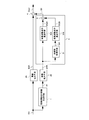
- FIG. FIG. 1 is a diagram showing a configuration of an image processing apparatus according to Embodiment 1 of the present invention, and can be used as, for example, the image processing apparatus U1 in the image display apparatus shown in FIG.
- the image display device shown in FIG. 24 includes an image processing device U1 and a display unit 9, and the display unit 9 displays an image.
- the image processing apparatus includes an image enlarging means 2A, a high frequency component image generating means 1, an image enlarging means 2B, a high frequency component image processing means 3, and an adding means 4.
- the image enlarging means 2A enlarges the input image Din and generates an enlarged image D2A.
- the high frequency component image generation means 1 extracts only the high frequency component of the input image Din and generates a high frequency component image D1.
- the image enlarging means 2B enlarges the high frequency component image D1 output from the high frequency component image generating means 1 and generates an enlarged image D2B.
- the high frequency component image processing means 3 extracts a high frequency component of the enlarged image D2B output from the image enlargement means 2B and generates a high frequency component image D3.
- the adding means 4 adds the high frequency component image D3 output from the high frequency component image processing means 3 to the enlarged image D2A output from the enlarging means 2A, and the result is the final enlarged image, that is, the output image. Output as Dout.
- the output of the adding means 4 is supplied to the display unit 9 in the image display device shown in FIG. 24 and used for image display by the display unit 9.
- processing such as enlargement, high-frequency generation, and high-frequency component processing is performed on an “image”. Specifically, it is performed on digital data representing an image. .
- the description of “image” may specifically mean “image data”.
- the frequency component of the high frequency component image D3 is included in the enlarged image D2A.
- the frequency band is higher than the frequency component. Therefore, by adding the high frequency component image D3 to the enlarged image D2A in the adding means 4, it is possible to obtain an enlarged image Dout containing a large amount of high frequency components.
- the image enlarging means 2A enlarges the image in at least one of the horizontal direction and the vertical direction.
- the image enlarging means 2A enlarges the image in the horizontal direction and the vertical direction at the same magnification, but instead, the magnifications differ in the horizontal direction and the vertical direction. It is also possible to perform enlargement with. Further, enlargement may be performed only in one of the horizontal direction and the vertical direction. For example, when the display screen is horizontally long with respect to the input image, enlargement may be performed only in the horizontal direction.
- FIG. 2 is a diagram showing details of the configuration of the image processing apparatus according to Embodiment 1 of the present invention shown in FIG. 1, and particularly shows the configuration of the high-frequency component image processing means 3 in detail.
- the high frequency component image processing means 3 includes high frequency component passing means 32A, non-linear processing means 31, high frequency component passing means 32B, and adding means 5.
- the high frequency component passing means 32A generates an intermediate image D32A in which only the high frequency component included in the enlarged image D2B is extracted.
- the nonlinear processing means 31 generates a nonlinear processed image D31 obtained by performing nonlinear processing for sharpening an edge, which will be described later, on the enlarged image D2B, and the high frequency component passing means 32B is a high frequency component included in the nonlinear processed image D31.
- An intermediate image D32B from which only components are extracted is output.
- the result obtained by adding the intermediate image D32A and the intermediate image D32B by the adding means 5 is output as the high frequency component image D3.
- FIG. 3 is a diagram showing further details of the configuration of the image processing apparatus according to the first embodiment of the present invention.
- the high frequency component image generating means 1, the image enlarging means 2B, the high frequency component passing means 32A, and the nonlinear processing means 31 are shown.
- the configuration of the high frequency component passing means 32B is described in detail. The operation of the components of the image processing apparatus shown in FIG. 3 will be described below.
- the high-frequency component image generation means 1 is a horizontal high-frequency component image generation means 1h and a vertical high-frequency component image generation means for generating a horizontal high-frequency component image D1h and a vertical high-frequency component image D1v, respectively, by a method described later. 1v is provided.
- the high frequency component image D1 is composed of the horizontal high frequency component image D1h and the vertical high frequency component image D1v.
- the image enlarging unit 2B includes an image enlarging unit 2Bh that generates an enlarged image D2Bh obtained by enlarging the horizontal high-frequency component image D1h, and an image enlarging unit 2Bv that generates an enlarged image D2Bv obtained by enlarging the vertical high-frequency component image D1v.
- the enlarged image D2B is composed of the enlarged image D2Bh and the enlarged image D2Bv.
- the image enlarging means 2A When the image enlarging means 2A enlarges in both the horizontal and vertical directions, the image enlarging means 2Bh enlarges the horizontal high frequency component image D1h in both the horizontal and vertical directions, and the image enlarging means 2Bv The direction high frequency component image D1v is enlarged in both the horizontal direction and the vertical direction.
- the enlargement of the horizontal high-frequency component image D1h and the vertical high-frequency component image D1v by the image enlargement means 2Bh and 2Bv is performed at the same magnification for each of the enlargement by the image enlargement means 2A and the horizontal and vertical directions.
- the high frequency component passing means 32A includes a horizontal high frequency component passing means 32Ah that generates an intermediate image D32Ah obtained by extracting only a horizontal high frequency component included in the enlarged image D2Bh, and a vertical high frequency component of the enlarged image D2Bv. Only the high-frequency component passing means 32Av in the vertical direction for generating the intermediate image D32Av obtained by extracting only the intermediate image D32Av and the adding means 6A for adding the intermediate image D32Ah and the intermediate image D32Av. The adding means 6A adds the intermediate image D32Ah and the intermediate image D32Av. The result is output as an intermediate image D32A.
- the non-linear processing means 31 generates a non-linearly processed non-linearly processed image D31h for sharpening edges including stepwise changes in signal values of pixels arranged in the horizontal direction in the method described later on the enlarged image D2Bh.
- Vertical non-linear processing for generating non-linear processing image D31v subjected to non-linear processing for sharpening of an edge including stepwise changes in signal values of pixels arranged in the vertical direction by processing means 31h and enlarged image D2Bv in a method described later Means 31v are provided.
- the nonlinear processed image D31 is composed of the nonlinear processed image D31h and the nonlinear processed image D31v.
- the high frequency component passing means 32B includes only a horizontal high frequency component passing means 32Bh that generates an intermediate image D32Bh obtained by extracting only the high frequency components included in the nonlinear processed image D31h, and a high frequency component included in the nonlinear processed image D31v.
- a vertical high frequency component passing means 32Bv for generating the extracted intermediate image D32Bv and an adding means 6B for adding the intermediate image D32Bh and the intermediate image D32Bv are provided. The result of adding the intermediate image D32Bh and the intermediate image D32Bv by the adding means 6B , And output as an intermediate image D32B.
- the image enlarging means 2A generates an enlarged image D2A obtained by enlarging the input image Din twice in both the horizontal direction and the vertical direction.
- FIGS. 4A to 4D are diagrams schematically showing an example of the procedure for generating the enlarged image D2A in the image enlargement unit 2A
- FIG. 5 is a diagram showing an example of the image enlargement unit 2A. .
- the image enlarging means 2A includes zero insertion means 21A and low frequency component passing means 22A.
- the operations of the zero insertion means 21A and the low frequency component passing means 22A will be described with reference to FIGS. 4 (a) to 4 (d).
- 4A shows the input image Din (particularly, the arrangement of pixels constituting a part of the image)
- FIG. 4B shows the zero insertion image D21A generated by the zero insertion means 21A
- FIG. 4D shows the filter coefficient used when the enlarged image D2A is generated by the low-frequency component passing unit 22A
- FIG. 4D shows the enlarged image D2A generated by the low-frequency component passing unit 22A.
- 4B and 4D show horizontal coordinates X and vertical coordinates Y corresponding to the positions of the pixels.
- the zero insertion means 21A In the zero insertion means 21A, one pixel per pixel (in the input image Din) having a pixel value 0 with respect to the input image Din (one between two adjacent pixels) in the horizontal direction, and one in the vertical direction A zero-inserted image D21A is generated in which one (one between two adjacent lines) is inserted per line (of the input image Din).
- PXY represents a pixel at coordinates (X, Y) in the input pixel Din
- P′XY represents a coordinate (X, Y) in the zero insertion image D21A
- the pixel PXY included in the input image Din is P ′ (2X ⁇ 1) (2Y ⁇ 1) in the zero insertion image D21A.
- the low-frequency passing means 22A performs the filter operation represented by the filter coefficient shown in FIG. 4C on the zero insertion image D21A to generate the enlarged image D2A shown in FIG.
- the pixel value QXY of the pixel at coordinates (X, Y) included in the enlarged image D2A is calculated as in the following equation (1).
- QXY (4/16) ⁇ ⁇ P ′ (X ⁇ 1) (Y ⁇ 1) + 2P′X (Y ⁇ 1) + P ′ (X + 1) (Y ⁇ 1) + 2P ′ (X ⁇ 1) Y + 4P′XY + 2P ′ (X + 1) Y + P ′ (X ⁇ 1) (Y + 1) + 2P′X (Y + 1) + P ′ (X + 1) (Y + 1) ⁇ ... (1)
- the processing in the low-frequency component passage means 22A represented by the equation (1) corresponds to extracting the low-frequency component of the zero insertion image D21A. To do.
- the horizontal high-frequency component image generating means 1h applies a high-pass filter using, for example, a predetermined number of pixels in the vicinity of each pixel of the input image Din and the horizontal direction to the input image Din, and applies the horizontal high-frequency component image. D1h is generated.
- the vertical high frequency component image generating means 1h applies a high pass filter to the input image Din by applying a high pass filter using, for example, a predetermined number of pixels in the vicinity of each pixel of the input image Din and the vertical direction.
- a component image D1v is generated.
- the horizontal high frequency component image D1h includes a high frequency component in the horizontal direction of the input image Din
- the vertical high frequency component image D1v includes a high frequency component in the vertical direction of the input image Din.
- a hyperfilter performed by the horizontal high frequency component image generating means 1h for example, a low frequency component in the horizontal direction (or a predetermined line aligned in the horizontal direction with respect to each pixel) from the input signal to the means 1h.
- a simple average value or a weighted average value of pixel values in a local region composed of a number of pixels it is possible to perform processing for extracting a high frequency component.
- the processing for applying the hyperfilter performed by the vertical high frequency component image generating means 1v for example, from the input signal to the means 1v, the vertical low frequency component (or the vertical direction for each pixel).
- the vertical low frequency component or the vertical direction for each pixel.
- the image enlarging means 2Bh generates an enlarged image D2Bh obtained by enlarging the horizontal high-frequency component image D1h twice in both the horizontal and vertical directions, and the image enlarging means 2Bv converts the vertical high-frequency component image D1v in both the horizontal and vertical directions.
- An enlarged image D2Bv enlarged twice is generated.
- Each of the image enlarging means 2Bh and the image enlarging means 2Bv can be configured in the same manner as the image enlarging means 2A described with reference to FIG. Therefore, the image enlarging means 2B composed of the image enlarging means 2Bh and the image enlarging means 2Bv can be shown as shown in FIG.
- the input of the image enlarging means 2Bh is a horizontal high frequency component image D1h, and the output is an enlarged image D2Bh.
- the input of the image enlarging means 2Bv is a vertical high frequency component image D1v, and the output is an enlarged image D2Bv.
- the image enlarging unit 2Bh includes a zero insertion unit 21Bh and a low frequency component passing unit 22Bh
- the image enlarging unit 2Bv includes a zero insertion unit 21Bv and a low frequency component passing unit 22Bv.
- Each of the zero insertion means 21Bh and the zero insertion means 21Bv is the same as the zero insertion means 21A of FIG. 5, and each of the low frequency component passage means 22Bh and the low frequency component passage means 22Bv is a low frequency component of FIG. This is the same as the passing means 22A.
- the zero insertion image D21B as the output of the zero insertion means 21B is composed of the zero insertion image D21Bh output from the zero insertion means 21Bh and the zero insertion image D21Bv output from the zero insertion means 21Bv.
- the enlarged image D2B as the output of the low frequency component passing means 22B is composed of the enlarged image D2Bh outputted from the low frequency component passing means 22Bh and the enlarged image D2Bv outputted from the low frequency component passing means 22Bv.
- the high frequency component passing means 32A includes a horizontal high frequency component passing means 32Ah, a vertical high frequency component passing means 32Av, and an adding means 6A.
- the horizontal high frequency component passing means 32Ah applies a high pass filter in the horizontal direction to the enlarged image D2Bh to generate an intermediate image D32Ah.
- the vertical high frequency component passing unit 32Av applies a high-pass filter in the vertical direction to the enlarged image D2Bv to generate an intermediate image D32Av.
- the adding means 6A adds the intermediate image D32Ah and the intermediate image D32Av to generate the intermediate image D32A.
- the intermediate image D32A generated in this way is output from the high frequency component passing means 32A.
- the process of applying a hyperfilter performed by the horizontal high-frequency component passing means 32Ah is performed in the same manner as the process of the horizontal high-frequency component image generating means 1h, and the process of applying the hyperfilter performed by the vertical high-frequency component passing means 32Av. Can be performed in the same manner as the processing in the vertical high-frequency component image generation means 1v. That is, the process for applying the hyperfilter performed by the horizontal high-frequency component passing means 32Ah is, for example, from the input signal to the means 32Ah in the horizontal direction, as in the process of the horizontal high-frequency component image generating means 1h.
- the nonlinear processing means 31 includes a horizontal nonlinear processing means 31h and a vertical nonlinear processing 31v.
- the horizontal non-linear processing means 31h and the vertical non-linear processing means 31v are configured in the same manner. However, the horizontal non-linear processing means 31h performs horizontal processing, and the vertical non-linear processing means 31v performs vertical processing.
- FIG. 7 is a diagram showing the internal configuration of the horizontal nonlinear processing means 31h.
- the horizontal non-linear processing unit 31h includes a zero-cross determining unit 311h and a signal amplifying unit 312v.
- the zero cross determination means 311h confirms the change in the pixel value in the inputted enlarged image D2Bh along the horizontal direction. Then, a point where the pixel value changes from a positive value to a negative value or from a negative value to a positive value is regarded as a zero cross point, and pixels before and after the zero cross point by the signal D311h (in the illustrated example, each of the pixels immediately before and after 1 pixel) is transmitted to the signal amplifying means 312h. In the horizontal non-linear processing means 31h, pixels located on the left and right of the zero cross point are recognized as pixels before and after the zero cross point.
- the signal amplifying unit 312h specifies pixels before and after the zero cross point based on the signal D311h, and amplifies the pixel value only for the pixels before and after the zero cross point (increases the absolute value) D31h. Is generated. That is, the amplification factor for the pixel values of the pixels before and after the zero cross point is set to a value larger than 1, and the amplification factors for the pixel values of the other pixels are set to 1. By such processing, edge sharpening including stepwise changes in signal values of pixels arranged in the horizontal direction is performed.
- FIG. 8 is a diagram showing the internal configuration of the vertical nonlinear processing means 31v.
- the vertical nonlinear processing means 31v includes a zero cross determination means 311v and a signal amplification means 312v.
- the zero cross determination unit 311v confirms the change in the pixel value in the input enlarged image D2Bh along the vertical direction.
- a point where the pixel value changes from a positive value to a negative value or from a negative value to a positive value is regarded as a zero cross point, and pixels before and after the zero cross point by the signal D311v (in the illustrated example, the respective pixels immediately before and after 1 pixel) is transmitted to the signal amplifying means 312v.
- the vertical nonlinear processing means 31v recognizes pixels located above and below the zero cross point as pixels before and after the zero cross point.
- the signal amplifying means 312v specifies pixels before and after the zero cross point based on the signal D311v, and amplifies the pixel values only for pixels before and after the zero cross point (increases the absolute value) D31v. Is generated. That is, the amplification factor for the pixel values of the pixels before and after the zero cross point is set to a value larger than 1, and the amplification factors for the pixel values of the other pixels are set to 1. By such processing, edge sharpening including step-like changes in signal values of pixels arranged in the vertical direction is performed.
- the high frequency component passing means 32B includes a horizontal high frequency component passing means 32Bh, a vertical high frequency component passing means 32Bv, and an adding means 6B.
- the horizontal high-frequency component passing means 32Bh applies a high-pass filter in the horizontal direction to the nonlinear processed image D31h to generate an intermediate image D32Bh.
- the vertical high frequency component passing means 32Bv applies a high pass filter in the vertical direction to the nonlinear processed image D31v to generate an intermediate image D32Bv.
- the adding unit 6B adds the intermediate image D32Bh and the intermediate image D32Bv to generate the intermediate image D32B.
- the intermediate image D32B generated in this way is output from the high frequency component passing means 32B.
- the process of applying the hyperfilter performed by the horizontal high frequency component passing means 32Bh is performed in the same manner as the process of the horizontal high frequency component image generating means 1h, and the process of applying the hyperfilter performed by the vertical high frequency component passing means 32Bv. Can be performed in the same manner as the processing in the vertical high-frequency component image generation means 1v. That is, as the processing for applying the hyperfilter performed by the horizontal high frequency component passing means 32Bh, for example, from the input signal to the means 32Bh, the horizontal low frequency component (or the horizontal alignment with respect to each pixel). By subtracting a simple average value or a weighted average value of pixel values in a local region composed of a predetermined number of pixels, a process for extracting a high frequency component can be performed.
- the processing for applying the hyperfilter performed by the vertical high frequency component passing means 32Bv for example, from the input signal to the means 32Bv, the low frequency component in the vertical direction (or the vertical alignment with respect to each pixel).
- the simple average value or the weighted average value of the pixel values in the local area composed of the predetermined number of pixels it is possible to perform processing for extracting the high frequency component.
- the adding means 5 outputs the result of adding the intermediate image D32A and the intermediate image D32B as a high frequency component image D3.
- the adding means 4 adds the enlarged image D2A and the high frequency component image D3. Then, an image obtained as a result of adding the enlarged image D2A and the high frequency component image D3 in the adding means 4 is output from the image processing apparatus as a final enlarged image Dout.
- addition process in the addition means 4 is not limited to simple addition, and may be a process of adding the enlarged image D2A and the high frequency component image D3 with different weights. The same applies to the adding means 5 in the high frequency component image processing means 3.
- the image processing apparatus adds the enlarged image D2A and the high frequency component image D3 to generate a final enlarged image (output image) Dout.
- the enlarged image D2A includes a frequency component corresponding to a frequency lower than the Nyquist frequency Fn of the input image Din
- the high frequency component image D3 includes a frequency component corresponding to a frequency equal to or higher than the Nyquist frequency Fn of the input image Din. Therefore, the enlarged image Dout generated by adding the enlarged image D2A and the high-frequency component image D3 has frequency components over all frequency regions that reach the Nyquist frequency after image enlargement.
- the enlarged image D2A has a frequency component corresponding to a frequency lower than the Nyquist frequency Fn of the input image Din.
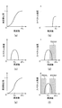
- FIGS. 9A to 9D are diagrams schematically showing the operation when the enlarged image D2A is generated from the input image Din.
- FIG. 9A shows the frequency spectrum of the input image Din.
- FIG. 9C shows the frequency spectrum of the zero insertion image D21A,
- FIG. 9C shows the frequency response of the low frequency component passing means 22A, and
- FIG. 9D shows the frequency spectrum of the enlarged image D2A.
- the frequency spectrum of the input image Din will be described. Normally, natural images and the like are input from the input image Din, but the spectral intensities of these images are concentrated around the origin of the frequency space. Therefore, the frequency spectrum of the input image Din can be expressed as shown in FIG.
- the vertical axis in FIG. 9A represents the spectral intensity
- the horizontal axis represents the spatial frequency
- Fn represents the Nyquist frequency of the input image Din.
- the normal input image Din is a two-dimensional image
- its frequency spectrum is also represented in a two-dimensional frequency space, but its shape is isotropic with the frequency spectrum shown in FIG. It will spread to. Therefore, in order to describe the frequency spectrum, it is only necessary to show the shape of one dimension at a minimum. In the future, unless otherwise specified, the shape of the frequency space will be described by showing only one dimension.
- the frequency spectrum of the zero insertion image D21A will be described.
- the frequency spectrum of the zero insertion image D21A is as shown in FIG.
- the frequency response of the low frequency component passing means 22A will be described. As described above, since the calculation in the low-frequency passage means 22A is a low-pass filter, the frequency response of the low-frequency component passage means 22A becomes lower as the frequency becomes higher, as shown in FIG. 9C.
- An enlarged image D2A is generated by passing the zero insertion image D21A having the frequency spectrum shown in FIG. 9B through the low-frequency component passing means 22A having the frequency response shown in FIG. 9C. Therefore, the frequency spectrum of the enlarged image D2A is obtained by removing the region R2AH on the high frequency side indicated by the oblique lines from the frequency spectrum of D21A.
- the enlarged image D2A mainly has a frequency component corresponding to a frequency lower than the Nyquist frequency Fn of the input image Din.
- the high frequency component image D3 mainly has a frequency component corresponding to a frequency equal to or higher than the Nyquist frequency Fn of the input image Din.
- the high frequency component image D3 is obtained by adding the intermediate image D32A and the intermediate image D32B.
- the intermediate image D32A has a frequency component corresponding to a frequency close to the Nyquist frequency Fn of the input image Din, and the intermediate image D32B is particularly input. Since it has a frequency component corresponding to a frequency higher than the Nyquist frequency Fn of the image Din and the frequency component of the intermediate images D32A and D32B is added in the high frequency component image D3, a frequency component equal to or higher than the Nyquist frequency Fn of the input image Din is added. Will have.
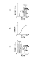
- FIG. 10 (a) to 10 (f) are diagrams schematically showing the action when the intermediate image D32A is generated
- FIG. 10 (a) shows the frequency response of the high-frequency component image generation means 1 as shown in FIG. b) shows the frequency spectrum of the high-frequency component image D1 (or D1h or D1v)
- FIG. 10C shows the frequency of the zero insertion image D21B (or D21Bh or D21Bv) generated by the zero insertion means 21B in the enlargement means 2B.
- FIG. 10D shows the frequency spectrum of the enlarged image D2B (or D2Bh or D2Bv), FIG.
- FIG. 10E shows the frequency response of the high-frequency component passing means 32A (or 32Ah or 32Av), and FIG. ) Represents the frequency spectrum of the intermediate image D32A (or D32Ah or D32Av) output from the high frequency component passing means 32A.
- the frequency response of the high frequency component image generating means 1 and the frequency spectrum of the high frequency component image D1 will be described. Since the high frequency component image generating means 1 generates the high frequency component image D1 using a high pass filter, the frequency response of the high frequency component image generating means 1 becomes higher as the frequency becomes higher as shown in FIG. . Since the input image Din having the frequency spectrum shown in FIG. 9A passes through the high-pass filter having the frequency response shown in FIG. 10A, the high frequency component image D1 is obtained. As shown in FIG. 10B, the frequency spectrum is small in the low frequency region and has a certain intensity only in the high frequency region.
- the frequency spectrum of the zero insertion image D21B in the enlarging means 2B will be described. Similar to the description of the zero insertion unit 21A of the image enlargement unit 2A, since the aliasing occurs by the zero insertion unit 21B, the frequency spectrum of the zero insertion image D21B in the enlargement unit 2B is as shown in FIG. become.
- the frequency response of the enlarged image D2B will be described.
- the frequency spectrum on the high frequency component side of the zero insertion image D21B is removed by the low frequency component passing means 22B, so that the frequency spectrum of the enlarged image D2B is high as shown in FIG.
- the frequency side region R32AH is removed.
- the frequency response of the high frequency component passing means 32A and the frequency spectrum of the intermediate image D32A will be described. Since the high frequency component passing means 32A is a high pass filter, its frequency response becomes higher as the frequency becomes higher as shown in FIG.
- the intermediate image D32A is generated by passing the enlarged image D2B having the frequency spectrum shown in FIG. 10D through the high-pass filter having the frequency response shown in FIG. Therefore, as shown in FIG. 10F, the frequency response of the intermediate image D32A is obtained by removing the region R32AL on the lower frequency side from the frequency spectrum of the enlarged image D2B shown in FIG.
- the intermediate image D32A mainly has a frequency component corresponding to a frequency close to the Nyquist frequency Fn of the input image Din.
- FIG. 11 (a) to 11 (c) are diagrams schematically showing the action when the intermediate image D32B is generated.
- FIG. 11 (a) is a diagram showing how high frequency components are generated by the nonlinear means 31 (or 31h or 31v).
- FIG. 11B shows the frequency response of the high-frequency component passing means 32B, and
- FIG. 11C shows the frequency spectrum of the intermediate image D32B.
- FIG. 11A is a diagram schematically showing the state.
- the intermediate image D32B is generated by passing the nonlinear processed image D31 through the high frequency component passing means 32B.
- the high frequency component passing means 32B is a high pass filter, and its frequency response becomes higher as the frequency becomes higher as shown in FIG. Accordingly, as shown in FIG. 11C, the frequency spectrum of the intermediate image D32B is higher than the Nyquist frequency Fn of the input image Din because the low-frequency region R32BL is removed from the frequency spectrum of the nonlinear processed image D31. It corresponds to the frequency.
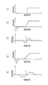
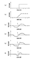
- FIG. 12A to 12E show a step edge signal representing an image (step image) in which component values such as luminance and saturation change stepwise, and when the step edge signal is sampled at different sampling frequencies.
- FIG. 12A shows a step edge signal.
- FIG. 12B shows a signal obtained by sampling the step edge signal at the sampling interval S1
- FIG. 12C shows a high frequency component of the signal obtained by sampling the step edge signal at the interval S1
- FIG. d) shows a signal obtained by sampling the step edge signal at the sampling interval S2
- FIG. 12E shows a high frequency component of the signal obtained by sampling the step edge signal at the interval S1.
- the sampling interval S1 is shorter than the sampling interval S2, and shortening the sampling interval is the same as enlarging the image.
- the center of the edge appears as a zero cross point Z in the high frequency component signal (FIGS. 12C and 12E).
- the slope of the high-frequency component signal before and after the zero-cross point Z decreases as the sampling interval is shortened ( Alternatively, the position of the point giving the local maximum and minimum values of the high-frequency component near the zero-cross point Z also approaches the zero-cross point Z (according to the enlargement of the image).
- the high frequency component of the input image Din is taken out, the change is made steep near the zero cross, and the point giving the local maximum and minimum values near the zero cross is brought close to the zero cross point.
- a high-frequency component that is not included in the resolution of Din (or higher than the Nyquist frequency of the input image Din) is generated, thereby making it possible to sharpen the edge.
- FIGS. 13A to 13F are diagrams schematically showing a procedure of high frequency component generation by the high frequency component image generation means 1, the image enlargement means 2B, the nonlinear processing means 31, and the high frequency component passage means 32B.
- FIG. 13A shows an image (step image) in which component values such as luminance and saturation change in steps
- FIG. 13B shows an input image Din corresponding to the step image
- FIG. The frequency component image D1 shows the enlarged image D2B
- FIG. 13E shows the nonlinear processed image D31
- FIG. 13F shows the intermediate image D32B.
- each is described as a one-dimensional signal.
- the input image Din corresponding to the step image and the high-frequency component image D1 are as described in FIGS. 12A to 12E, and the description thereof is omitted. First, the enlarged image D1 will be described.
- the enlarged image D1 passes through the low-frequency component after inserting one pixel per pixel (image D1) with a pixel value of 0 into the high-frequency component image D1 by the zero insertion means 21B. It is obtained by extracting the low frequency component by means 22B. Extracting the low frequency component is the same as obtaining an average pixel value in the local region for the high frequency component image D1 (FIG. 13C), and the enlarged image D2B (or D2Bh or D2Bv) is shown in FIG. As shown in d), the signal has the same shape as the high-frequency component image D1 and has an increased sampling number.
- the nonlinear processed image D31 is output as a result of the nonlinear processing means 31 detecting the zero cross point Z in the enlarged image D1 and amplifying the pixel values of the pixels before and after the zero cross point Z. Therefore, the nonlinear processed image D31 (or D31h or D31v) is a signal as shown in FIG.
- the intermediate image D32B (FIG. 13 (f)) is obtained by extracting the high frequency components of the nonlinear processed image D31 (FIG. 13 (e)) by the high frequency component passing means 32B.
- the high frequency component can be extracted by subtracting the low frequency component of the input signal (or a simple average value or a weighted average value of pixel values in the local region) from the input signal.
- the pixel values of the pixels before and after the zero cross point Z are amplified by the signal amplifying means 312h and 312v. The difference from is greater.
- the difference from the average pixel value in the local region is a small value. Therefore, compared with the enlarged image D2B (FIG. 13D), in the intermediate image D32B (FIG. 13F), the point giving the local maximum value and minimum value in the vicinity of the zero-cross point Z is closer to the zero-cross point Z. And get closer.
- the point that gives the local maximum and minimum values approaches the zero-cross point Z, the signal change near the zero-cross point also becomes abrupt.
- the intermediate image D32B includes a high frequency component that is not included in the resolution of the input image Din.
- the nonlinear processing means 31 amplifies pixel values around the zero cross point of the enlarged image D2B, thereby generating a high frequency component corresponding to a frequency higher than the Nyquist frequency Fn of the input image Din.
- the intermediate image D32B is generated by extracting the high frequency component generated by the nonlinear processing means 31 by the high frequency component passing means 32B, it has a high frequency component corresponding to a frequency higher than the Nyquist frequency Fn of the input image Din. It becomes an image.
- the high frequency component image D3 Since the high frequency component image D3 is obtained by adding the intermediate image D32A and the intermediate image D32B, the high frequency component image D3 includes both the frequency component of the intermediate image D32A and the frequency component of the intermediate image D32B. Yes.
- the intermediate image D32A includes a frequency component corresponding to a frequency close to the Nyquist frequency Fn of the input image Din
- the intermediate image D32B includes a frequency component corresponding to a frequency higher than the Nyquist frequency Fn of the input image Din. Therefore, the high frequency component image D3 includes frequency components equal to or higher than the Nyquist frequency Fn of the input image Din.
- the high frequency component image D1 generated by the high frequency component image generation means 1 is enlarged by the image enlargement means 2B, and further processed by the high frequency component image processing means 3, so that the frequency equal to or higher than the Nyquist frequency Fn of the input image Din.
- a high frequency component image D3 having components can be obtained.
- FIG. 14 shows the combined frequency components of the enlarged image D2A and the high frequency component image D3.
- the enlarged image D2A mainly includes a frequency component corresponding to a region RL corresponding to a frequency lower than the Nyquist frequency Fn of the input image Din.
- a frequency component corresponding to a frequency equal to or higher than the Nyquist frequency Fn of the input image Din is included.
- the high-frequency component image processing unit 3 processes the image enlarging unit 2B obtained by enlarging the high-frequency component image D1 generated by the high-frequency component image generating unit 1 with the enlarging unit 2B.
- a high frequency component image D3 including a frequency component corresponding to a frequency equal to or higher than the Nyquist frequency Fn of Din can be obtained.
- the adding means 4 an enlarged image D2A including a frequency component in a region corresponding to a frequency lower than the Nyquist frequency Fn of the input image Din and a high frequency including a frequency component in a region corresponding to a frequency equal to or higher than the Nyquist frequency Fn of the input image Din. Since the enlarged image Dout is generated by adding the frequency component images D3, a high frequency component can be sufficiently given to the enlarged image Dout, and an enlarged image Dout with a sense of resolution can be obtained.
- the high frequency component image generation means 1 generates a horizontal high frequency component image D1h obtained by extracting the horizontal high frequency component and a vertical high frequency component image D1v obtained by extracting the vertical high frequency component. It is possible to generate a frequency component corresponding to a frequency equal to or higher than the Nyquist frequency Fn of the input image Din in any one of the horizontal direction and the vertical direction of the image. That is, by applying a horizontal high-pass filter to the enlarged image D2Bh obtained by enlarging the horizontal high-frequency component image D1h by the image enlarging means 2Bh by the horizontal high-frequency component passing means 32Ah, the Nyquist of the input image Din with respect to the horizontal direction.
- An intermediate image D32Ah having a frequency component corresponding to a frequency close to the frequency Fn is generated.
- the enlarged image D2Bv obtained by enlarging the vertical high frequency component image D1v with the image enlarging means 2Bv is compared with the vertical high frequency component passing means 32Av.
- an intermediate image D32Av having a frequency component corresponding to a frequency close to the Nyquist frequency Fn of the input image Din in the vertical direction is generated, and the intermediate image D32Ah and the intermediate image D32Av are added by the adding unit 6A.
- intermediate image D32A having a substantial frequency components at a frequency close to the Nyquist frequency Fn of the input image Din for both the horizontal and vertical directions is generated. Further, by applying a high-pass filter having different characteristics in the horizontal direction and the vertical direction, an intermediate image including frequency components corresponding to frequencies close to the Nyquist frequency Fn in the horizontal direction and the vertical direction in different levels. Can also be generated.
- a high-pass filter is applied to the non-linearly processed image D31h generated by performing non-linear processing on the enlarged image D2Bh by the horizontal non-linear processing means 31h, so that the input image in the horizontal direction can be obtained.
- An intermediate image D32Bh having a frequency component corresponding to a frequency higher than the Ninquist frequency Fn of Din is generated, and a nonlinear processed image D31v generated by performing nonlinear processing on the enlarged image D2Bv by the vertical nonlinear processing means 31v,
- a high-pass filter in the vertical high frequency component passing means 32Bv an intermediate image D32Bv having a frequency component corresponding to a frequency higher than the Nyquist frequency Fn of the input image Din in the vertical direction is generated, and the intermediate image D32Bh and the intermediate image D32Bv is added to 6B Adding to it to generate an intermediate image D32B, intermediate image D32B having corresponding frequency components to a frequency higher than the Nyquist frequency Fn of the input image Din for both the horizontal and vertical directions is generated.
- an intermediate image that includes frequency components corresponding to frequencies higher than the Nyquist frequency Fn in the horizontal direction and the vertical direction is generated. You can also. Then, the intermediate image D32A and the intermediate image D32B are added by the adding means 5 to obtain a high frequency component image D3, whereby a high frequency having a frequency component corresponding to a frequency equal to or higher than the Nyquist frequency Fn of the input image Din in any direction. A component image D3 can be obtained.
- the image enlarging means 2B generates an enlarged image D2B obtained by enlarging the high frequency component image D1 to a desired magnification both in the horizontal direction and the vertical direction, and the high frequency component image processing means 3 generates an enlarged image D2B based on the enlarged image D2B.
- the frequency component image D3 is generated, and the adding unit 4 adds the enlarged image D2A and the high frequency component image D3 to obtain the final enlarged image Dout.
- the horizontal enlargement factor and the vertical enlargement factor may not be the same, and enlargement may be performed only in one of the horizontal direction and the vertical direction.
- the high frequency component image generating means 1 has a horizontal high frequency component image generating means 1h and a vertical high frequency component image generating means 1v
- the image enlarging means 2B is an image enlarging means 2Bh and It has an image enlarging means 2Bv
- the high frequency component passing means 32A has a horizontal high frequency component passing means 32Ah and a vertical high frequency component passing means 32Av
- the non-linear processing means 31 has a horizontal non-linear processing means 31h and a vertical direction.
- the high-frequency component passing means 32B has a horizontal high-frequency component passing means 32Bh and a vertical high-frequency component passing means 32Bv.
- the high-frequency component image generating means has a non-linear processing means 31v. 1 has only the horizontal high frequency component image generating means 1h, and the image enlarging means 2B has only the image enlarging means 2Bh.
- the high frequency component passing means 32A has only the horizontal high frequency component passing means 32Ah
- the nonlinear processing means 31 has only the horizontal nonlinear processing means 31h
- the high frequency component passing means 32B has the horizontal high frequency component passing.
- the high frequency component image generating unit 1 may include only the vertical high frequency component image generating unit 1v
- the image enlarging unit 2B may include only the image enlarging unit 2Bv
- the component passing means 32A has only the vertical high frequency component passing means 32Av
- the nonlinear processing means 31 has only the vertical nonlinear processing means 31v
- the high frequency component passing means 32B has only the vertical high frequency component passing means 32Bv.
- the structure which has this may be sufficient.
- the amplification factor is increased only for one pixel before and after the zero cross point in both the horizontal direction and the vertical direction.
- the example of the amplification factor control is not limited to this, and may be appropriately changed according to, for example, the enlargement factor. You can also. This point will be described below with reference to FIGS. 15A to 15E and FIGS. 16A to 16F.
- FIG. 15A shows the step edge signal
- FIG. 15B shows the signal obtained by sampling the step edge signal at the sampling interval S1
- FIG. 15C shows the signal obtained by sampling the step edge signal at the sampling interval S1.
- 15 (d) shows a high frequency component of the signal (the signal shown in FIG. 15 (b))
- FIG. 15 (d) shows a signal obtained by sampling the step edge signal at an interval S3 that is three times the interval S1
- FIG. 15 (e) Represents a high frequency component of a signal obtained by sampling the step edge signal at the interval S3.
- the pixel positions PL1 and PR1 represent the boundary of the step edge signal (the point where the change in luminance starts and the point where it ends).
- the position of the pixel that gives the local maximum value and minimum value in the vicinity of the zero cross point Z substantially coincides with the position of the boundary of the step edge signal.
- FIG. 16A is a diagram schematically illustrating a procedure, in which FIG. 16A is an image (step image) in which component values such as luminance and saturation change stepwise, and FIG. 16B is an input image corresponding to the step image. Din, FIG. 16C shows the high frequency component image D1, FIG. 16D shows the enlarged image D2B, FIG. 16E shows the nonlinear processed image D31, and FIG. 16F shows the intermediate image D32B.
- each is described as a one-dimensional signal.
- pixel positions PL1 and PR1 that give local maximum and minimum values near the zero-cross point Z in the enlarged image D2B are the positions of the boundary of the step edge signal in the enlarged image D2B. Almost matches.
- the positions of PL1 and PR1 do not change, and the positions represented by PL1 and PR1 and the zero cross point The number of pixels existing between Z increases.
- the number of pixels existing between the positions represented by PL1 and PR1 and the zero-cross point Z increases as the enlargement ratio when generating the enlarged image D2B is increased (or the sampling interval is shortened).
- the position of the pixel giving the local maximum value and minimum value near the zero cross point Z is closer to the zero cross point Z, and the zero cross A pixel closer to the point than Z has a larger amplitude of a signal representing a high frequency component.
- the present invention is not limited to this, and the amplification factor for pixels existing in a predetermined region including the zero cross point Z may be a constant value greater than 1. Then, an intermediate image D32B corresponding to the sampling interval S1 as shown in FIG. 16F can be generated by extracting only the high frequency component from the enlarged image D2B generated in this way by high-pass filter processing.
- the amplification factor for pixels existing in a predetermined region including the zero-cross point Z may be set to a value larger than 1, and the amplification factors for the pixel values of the other pixels may be set to 1, and the positions PL1, PR1 and Since the number of pixels existing between the zero-cross points Z differs depending on the enlargement rate at the time of generating the enlarged image D2B, the pixels whose amplification factor is greater than 1 before and after the zero-cross point Z when generating the nonlinear processed image D31 from the enlarged image D2B. (The number of pixels existing in the predetermined area) and / or the amplification factor itself may be changed according to the enlargement factor of the image.
- the amplification factors for these pixels may also be changed according to the distance from the zero cross point Z. For example, the amplification factor may be increased as the pixel is closer to the zero cross point Z. Further, the size and amplification factor of the above-described region may be different between the horizontal nonlinear processing means 31h and the vertical nonlinear processing means 31v.
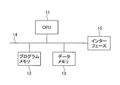
- FIG. 17 shows an image processing apparatus according to the second embodiment.
- the illustrated image processing apparatus includes a CPU 11, a program memory 12, a data memory 13, an interface 15, and a bus 14 for connecting them, and is used as, for example, an image processing unit U 1 in the image display apparatus shown in FIG. be able to.
- the CPU 11 operates according to a program stored in the program memory 12.
- Various data are stored in the data memory 13 in the course of operation.
- the enlarged image Dout generated as a result of the processing is supplied to the display unit 9 in the image display device shown in FIG. 24 via the interface 15 and used for display by the display unit 9.
- FIGS processing performed by the CPU 11 will be described with reference to FIGS.
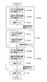
- FIG. 18 is a diagram illustrating a flow of an image processing method performed by the image processing apparatus of FIG. 17, and the image processing method illustrated in FIG. 18 includes an image enlargement step ST2A, a high frequency component image generation step ST1, and an image enlargement. Step ST2B, high frequency component image processing step ST3, and addition step ST4 are included.
- the image enlargement step ST2A generates an enlarged image D2A obtained by enlarging the input image Din input in the image input step (not shown) by the same processing as the image enlargement means 2A shown in FIGS.
- the high frequency component image generation step ST1 includes a horizontal direction high frequency component image generation step ST1h and a vertical direction high frequency component image generation step ST1v as shown in FIG.
- the input image Din is processed in the same manner as the horizontal direction high frequency component image generation unit 1h in FIG. 3 to generate the horizontal direction high frequency component image D1h.
- the vertical direction high frequency component image generation step ST1v the input image Din is processed in the same manner as the vertical direction high frequency component image generation means 1v in FIG. 3 to generate the vertical direction high frequency component image D1v.
- the image enlargement step ST2B includes an image enlargement step ST2Bh and an image enlargement step ST2Bv.
- the horizontal direction high frequency component image D1h generated in the horizontal direction high frequency component image generating step ST1h is subjected to the same processing as the image enlarging means 2Bh in FIG. 3 to generate an enlarged image D2Bh.
- the vertical high frequency component image D1v generated in the vertical high frequency component image generating step ST1v is subjected to the same processing as the image enlarging means 2Bv in FIG. 3 to generate an enlarged image D2Bv.
- the high frequency component image processing step ST3 includes a high frequency component passing step ST32A, a nonlinear processing step ST31, a high frequency component passing step ST32B, and an adding step ST5.
- the high frequency component passing step ST32A includes a horizontal high frequency component passing step ST32Ah, a vertical high frequency component passing step ST32Av, and an adding step ST6A.
- the non-linear processing step ST31 includes a horizontal non-linear processing step ST31h and a vertical non-linear processing step ST31v.
- the high frequency component passing step ST32B includes a horizontal high frequency component passing step ST32Bh, a vertical high frequency component passing step ST32Bv, and an adding step ST6B.
- the enlarged image D2Bh generated in the image enlarging step ST2Bh is subjected to the same processing as the horizontal direction high frequency component passing means 32Ah in FIG. 3 to generate an intermediate image D32Ah.
- the enlarged image D2Bv generated in the image enlarging step ST2Bv is subjected to the same processing as the vertical high frequency component passing means 32Av in FIG. 3 to generate an intermediate image D32Av.
- the intermediate image D32Ah generated in the horizontal high frequency component passing step ST32Ah and the intermediate image D32Av generated in the vertical high frequency component passing step ST32Av are added to generate an intermediate image D32A.
- the high frequency component passing step ST32A the same operation as the high frequency component passing means 32A of FIGS. 2 and 3 is performed.
- the horizontal non-linear processing step ST31h includes a zero-cross determination step ST311h and a signal amplification step ST312h.
- the operation of the horizontal nonlinear processing step ST31h is as follows. First, in the zero cross determination step ST311h, a change in the pixel value in the enlarged image D2Bh generated in the image enlargement step ST2Bh is confirmed along the horizontal direction. A location where the pixel value changes from a positive value to a negative value or from a negative value to a positive value is regarded as a zero cross point, and pixels located on the left and right sides of the zero cross point are specified.
- the pixel values of the pixels located on the left and right of the zero cross point specified in the zero cross determination step ST311h in the enlarged image D2Bh are amplified, and an image obtained as a result is generated as the nonlinear processed image D31h.
- the vertical non-linear processing step ST31v includes a zero cross determination step ST311v and a signal amplification step ST312v.
- the operation of the vertical nonlinear processing step ST31v is as follows. First, in the zero cross determination step ST311v, a change in pixel value in the enlarged image D2Bv generated in the image enlargement step ST2Bv is confirmed along the vertical direction. A portion where the pixel value changes from a positive value to a negative value or from a negative value to a positive value is regarded as a zero cross point, and pixels located above and below the zero cross point are specified.
- the signal amplification step ST312v the pixel values of the pixels located above and below the zero-cross point specified in the zero-cross determination step ST311v in the enlarged image D2Bv are amplified, and the resulting image is generated as the nonlinear processed image D31v.
- the non-linear processing step ST31 the same operation as the non-linear processing means 31 of FIGS. 2 and 3 is performed.
- the horizontal high-frequency component passing step ST32Bh in FIG. 21 applies a high-pass filter to the nonlinear processed image D31h generated in the horizontal nonlinear processing step ST31h to generate an intermediate image D32Bh.
- a high-pass filter is applied to the nonlinear processed image D31v generated in the vertical nonlinear processing step ST31v to generate an intermediate image D32Bv.
- intermediate image D32Bh and intermediate image D32Bv are added to generate intermediate image D32B. That is, in the high frequency component passing step ST32B, an operation similar to that of the high frequency component passing means 32B of FIGS. 2 and 3 is performed.
- step ST5 the intermediate image D32A generated in the high frequency component passing step ST32A and the intermediate image D32B generated in the high frequency component passing step ST32B are added to obtain a high frequency component image D3.
- step ST5 the same operation as that of the adding means 5 in FIGS. 2 and 3 is performed.
- step ST3 an operation similar to that of the high frequency component image processing means 3 in FIGS. 1, 2, and 3 is performed.
- the adding step ST4 generates an image Dout obtained by adding the enlarged image D2A generated in the image enlarging step ST2A and the high frequency component image D3 generated in the high frequency component image processing step ST3. Then, the generated image Dout is output as a final enlarged image through a step (not shown).
- the image can be enlarged by the same process as that of the image processing apparatus described in the first embodiment. Therefore, the same effect as that of the image processing apparatus described in the first embodiment can be obtained.
- the image processing apparatus according to the second embodiment can be used as a part of the image display apparatus similar to the image processing apparatus described in the first embodiment, the image Dout generated by the image processing apparatus according to the second embodiment.
- the image display apparatus that displays the same effect as the image processing apparatus described in the first embodiment can also be obtained.
- the image processing method implemented using the image processing apparatuses of the first and second embodiments and the image display method using the same can obtain the same effects.
- the configuration of the image display apparatus using the image processing apparatus described in the first or second embodiment is not limited to that shown in FIG.
Landscapes
- Engineering & Computer Science (AREA)
- Multimedia (AREA)
- Signal Processing (AREA)
- Computer Graphics (AREA)
- Physics & Mathematics (AREA)
- General Physics & Mathematics (AREA)
- Theoretical Computer Science (AREA)
- Image Processing (AREA)
- Editing Of Facsimile Originals (AREA)
- Facsimile Image Signal Circuits (AREA)
Abstract
Description
例えば特許文献1に記載された画像処理装置においては、各シフトレジスタからそれぞれ出力される主走査方向の隣り合った5個の画素データに所定の重み付け定数を乗算し、各画素データにおける乗算結果を加算するための演算回路を備え、画像データの拡大処理を行う場合に、演算回路での演算結果をこれらの画素データの中央の画素データとしてセレクタにて選択して出力している。
入力画像を拡大する画像処理装置において、
前記入力画像を拡大して第1の拡大画像を出力する第1の画像拡大手段と、
前記入力画像の高周波数成分を取り出して第1の高周波数成分画像を生成する高周波数成分画像生成手段と、
前記第1の高周波数成分画像を拡大して第2の拡大画像を出力する第2の画像拡大手段と、
前記第2の拡大画像の高周波数成分を取り出して第2の高周波数成分画像を生成する高周波数成分画像処理手段と、
前記第1の拡大画像と前記第2の高周波数成分画像を加算して、出力画像を生成する手段を有する
ことを特徴とする。
図1は本発明の実施の形態1による画像処理装置の構成を表す図であり、例えば図24に示す画像表示装置内の画像処理装置U1として用いることができる。なお、図24に示す画像表示装置は画像処理装置U1と表示部9から成り、表示部9によって画像表示が行われる。
画像拡大手段2Aは、入力画像Dinを拡大して拡大画像D2Aを生成する。高周波数成分画像生成手段1は、入力画像Dinの高周波数成分のみを取り出して高周波数成分画像D1を生成する。画像拡大手段2Bは、高周波数成分画像生成手段1から出力される高周波数成分画像D1を拡大して拡大画像D2Bを生成する。高周波数成分画像処理手段3は、画像拡大手段2Bから出力される拡大画像D2Bの高周波数成分を取り出して高周波数成分画像D3を生成する。加算手段4は、拡大手段2Aから出力される拡大画像D2Aに、高周波数成分画像処理手段3から出力される高周波数成分画像D3を加算して、その結果を最終的な拡大画像、即ち出力画像Doutとして出力する。加算手段4の出力は、図24に示す画像表示装置内の表示部9に供給され、表示部9による画像表示に用いられる。
なお、本明細書において、拡大、高周波数生成、高周波数成分処理などの処理は「画像」に対して行なわれる旨記載されるが、具体的には、画像を表すデジタルデータに対して行われる。また、「画像」との記載も具体的には「画像データ」を意味する場合がある。
「PXY」が入力画素Dinにおける、座標(X,Y)の画素を表し、「P’XY」がゼロ挿入画像D21Aにおける座標(X,Y)を表すとすれば、上記のゼロ挿入を行なう結果、入力画像Dinに含まれる画素PXYは、ゼロ挿入画像D21Aにおいて、P’(2X-1)(2Y-1)となる。
例えば、拡大画像D2Aに含まれる、座標(X,Y)の画素の画素値QXYは下記の式(1)のように計算される。
{P’(X-1)(Y-1)+2P’X(Y-1)+P’(X+1)(Y-1)
+2P’(X-1)Y+4P’XY+2P’(X+1)Y
+P’(X-1)(Y+1)+2P’X(Y+1)+P’(X+1)(Y+1)}
…(1)
一方、垂直方向高周波数成分画像生成手段1hは入力画像Dinに対して、入力画像Dinの各画素及びその垂直方向近傍にある、例えば所定数の画素を用いたハイパスフィルタをかけて垂直方向高周波数成分画像D1vを生成する。
水平方向高周波数成分画像D1hには、入力画像Dinの水平方向の高周波数成分が含まれ、垂直方向高周波数成分画像D1vには、入力画像Dinの垂直方向の高周波数成分が含まれる。
同様に、垂直方向高周波数成分画像生成手段1vで行なわれるハイパフィルタをかける処理としては、例えば、該手段1vへの入力信号からその垂直方向の低周波数成分(もしくは各画素に対して垂直方向に整列した所定数の画素から成る局所領域における画素値の単純平均値あるいは加重平均値)を差し引くことで高周波数成分を取り出す処理を行なうことができる。
画像拡大手段2Bhの入力は水平方向高周波数成分画像D1hであり、出力が拡大画像D2Bhとなる。画像拡大手段2Bvの入力は垂直方向高周波数成分画像D1vであり、出力が拡大画像D2Bvである。
ゼロ挿入手段21Bh及びゼロ挿入手段21Bvの各々は、図5のゼロ挿入手段21Aと同様のものであり、低周波数成分通過手段22Bh及び低周波数成分通過手段22Bvの各々は、図5の低周波数成分通過手段22Aと同様のものである。
低周波数成分通過手段22Bhから出力される拡大画像D2Bhと低周波数成分通過手段22Bvから出力される拡大画像D2Bvとで、低周波数成分通過手段22Bの出力としての拡大画像D2Bが構成される。
水平方向高周波数成分通過手段32Ahは、拡大画像D2Bhに水平方向のハイパスフィルタをかけ、中間画像D32Ahを生成する。
一方、垂直方向高周波数成分通過手段32Avは、拡大画像D2Bvに垂直方向のハイパスフィルタをかけ、中間画像D32Avを生成する。
そして加算手段6Aは、中間画像D32Ahと中間画像D32Avを加算することで中間画像D32Aを生成する。このようにして生成された中間画像D32Aが高周波数成分通過手段32Aから出力される。
即ち、水平方向高周波数成分通過手段32Ahで行なわれるハイパフィルタをかける処理としては、水平方向高周波数成分画像生成手段1hのける処理と同様に、例えば、該手段32Ahへの入力信号からその水平方向の低周波数成分(もしくは各画素に対して水平方向に整列した所定数の画素から成る局所領域における画素値の単純平均値あるいは加重平均値)を差し引くことで高周波数成分を取り出す処理を行なうことができる。
同様に、垂直方向高周波数成分通過手段32Avで行なわれるハイパフィルタをかける処理としては、例えば、該手段32Avへの入力信号からその垂直方向の低周波数成分(もしくは各画素に対して垂直方向に整列した所定数の画素から成る局所領域における画素値の単純平均値あるいは加重平均値)を差し引くことで高周波数成分を取り出す処理を行なうことができる。
なお、水平方向非線形処理手段31hではゼロクロス点の左右に位置する画素がゼロクロス点の前後にある画素として認識される。
信号増幅手段312hは、信号D311hをもとにゼロクロス点の前後にある画素を特定し、ゼロクロス点の前後にある画素についてのみその画素値を増幅させた(絶対値を大きくした)非線形処理画像D31hを生成する。すなわちゼロクロス点の前後にある画素の画素値に対する増幅率を1より大きな値とし、それ以外の画素の画素値に対する増幅率は1とする。
このような処理により、水平方向に並んだ画素の信号値のステップ状の変化を含むエッジの鮮鋭化が行なわれる。
なお、垂直方向非線形処理手段31vではゼロクロス点の上下に位置する画素がゼロクロス点の前後にある画素として認識される。
信号増幅手段312vは、信号D311vをもとにゼロクロス点の前後にある画素を特定し、ゼロクロス点の前後にある画素についてのみその画素値を増幅させた(絶対値を大きくした)非線形処理画像D31vを生成する。すなわちゼロクロス点の前後にある画素の画素値に対する増幅率を1より大きな値とし、それ以外の画素の画素値に対する増幅率は1とする。
このような処理により、垂直方向に並んだ画素の信号値のステップ状の変化を含むエッジの鮮鋭化が行なわれる。
水平方向高周波数成分通過手段32Bhは、非線形処理画像D31hに水平方向のハイパスフィルタをかけ、中間画像D32Bhを生成する。一方、垂直方向高周波数成分通過手段32Bvは、非線形処理画像D31vに垂直方向のハイパスフィルタをかけ、中間画像D32Bvを生成する。そして加算手段6Bは中間画像D32Bhと中間画像D32Bvを加算することで中間画像D32Bを生成する。このようにして生成された中間画像D32Bが高周波数成分通過手段32Bから出力される。
即ち、水平方向高周波数成分通過手段32Bhで行なわれるハイパフィルタをかける処理としては、例えば、該手段32Bhへの入力信号からその水平方向の低周波数成分(もしくは各画素に対して水平方向に整列した所定数の画素から成る局所領域における画素値の単純平均値あるいは加重平均値)を差し引くことで高周波数成分を取り出す処理を行なうことができる。
同様に、垂直方向高周波数成分通過手段32Bvで行なわれるハイパフィルタをかける処理としては、例えば、該手段32Bvへの入力信号からその垂直方向の低周波数成分(もしくは各画素に対して垂直方向に整列した所定数の画素から成る局所領域における画素値の単純平均値あるいは加重平均値)を差し引くことで高周波数成分を取り出す処理を行なうことができる。
本発明における画像処理装置では、拡大画像D2Aと高周波数成分画像D3を加算して最終的な拡大画像(出力画像)Doutを生成する。拡大画像D2Aは、入力画像Dinのナイキスト周波数Fnより低い周波数に相当する周波数成分を含み、高周波数成分画像D3は入力画像Dinのナイキスト周波数Fn以上の周波数に相当する周波数成分を含む。したがって、拡大画像D2Aと高周波数成分画像D3を加算して生成される拡大画像Doutは画像拡大後のナイキスト周波数に至る全ての周波数領域にわたって周波数成分を持つことになる。
図10(a)~(f)は中間画像D32Aを生成する際の作用を模式的に表した図であり、図10(a)は高周波数成分画像生成手段1の周波数応答を、図10(b)は高周波数成分画像D1(又はD1h若しくはD1v)の周波数スペクトルを、図10(c)は拡大手段2B内のゼロ挿入手段21Bによって生成されるゼロ挿入画像D21B(又はD21Bh若しくはD21Bv)の周波数スペクトルを、図10(d)は拡大画像D2B(又はD2Bh若しくはD2Bv)の周波数スペクトルを、図10(e)は高周波数成分通過手段32A(又は32Ah若しくは32Av)の周波数応答を、図10(f)は高周波数成分通過手段32Aから出力される中間画像D32A(又はD32Ah若しくはD32Av)の周波数スペクトルを表している。
図11(a)~(c)は中間画像D32Bを生成する際の作用を模式的に表した図であり、図11(a)は非線形手段31(又は31h若しくは31v)により高周波数成分が生成される様子を、図11(b)は高周波数成分通過手段32Bの周波数応答を、図11(c)は中間画像D32Bの周波数スペクトルを表している。
なお、サンプリング間隔S1はサンプリング間隔S2より短くなっており、サンプリング間隔を短くすることは画像を拡大することと同じである。
また、水平方向及び垂直方向について異なる特性のハイパスフィルタをかけることで、水平方向と垂直方向とで水平方向と垂直方向とでナイキスト周波数Fnに近い周波数に相当した周波数成分を異なる程度に含む中間画像を生成することもできる。
また、水平方向及び垂直方向について異なる特性の非線形処理及びハイパスフィルタリングを行なうことで、水平方向と垂直方向とでナイキスト周波数Fnより高い周波数に相当した周波数成分を異なる程度に含む中間画像を生成することもできる。
そして中間画像D32Aと中間画像D32Bを加算手段5で加算して高周波数成分画像D3を得ることで、任意の方向について入力画像Dinのナイキスト周波数Fn以上の周波数に相当した周波数成分を持った高周波数成分画像D3を得ることできる。
さらに、先にも述べたように、水平方向の拡大率と垂直方向の拡大率とは同じでなくても良く、また水平方向、垂直方向の一方についてのみ拡大を行なっても良い。
一方、ステップエッジ信号を短いサンプリング間隔でサンプリングした画像の高周波数成分を表す信号では、ゼロクロス点Z近傍での局所的な最大値、最小値を与える画素の位置はよりゼロクロス点Zに近づき、ゼロクロス点にZより近い画素ほど高周波数成分を表す信号の振幅が大きくなる。
そしてこのようにして生成した拡大画像D2Bからハイパスフィルタ処理によって高周波数成分のみを取り出すことで図16(f)に示すようなサンプリング間隔S1に対応した中間画像D32Bを生成できる。
実施の形態1では、本発明をハードウエアにより実現するものとして説明したが、図1に示される構成の一部又は全部をソフトウエアにより実現することも可能である。その場合の処理を図17、並びに図18~図23を参照して説明する。
図17は、実施の形態2の画像処理装置を示す。図示の画像処理装置は、CPU11と、プログラムメモリ12と、データメモリ13と、インターフェース15と、これらを接続するバス14を有し、例えば図24に示す画像表示装置内の画像処理部U1として用いることができる。
CPU11は、プログラムメモリ12に記憶されたプログラムに従って動作する。動作の過程で種々のデータをデータメモリ13に記憶させる。処理の結果生成される拡大画像Doutは、インターフェース15を介して図24に示す画像表示装置内の表示部9に供給され、表示部9による表示に用いられる。
以下、CPU11により行なわれる処理を図18~図23を参照して説明する。
画像拡大ステップST2Bhでは、水平方向高周波数成分画像生成ステップST1hで生成した水平方向高周波数成分画像D1hに対し、図3の画像拡大手段2Bhと同様の処理を行い、拡大画像D2Bhを生成する。
画像拡大ステップST2Bvでは、垂直方向高周波数成分画像生成ステップST1vで生成した垂直方向高周波数成分画像D1vに対し、図3の画像拡大手段2Bvと同様の処理を行い、拡大画像D2Bvを生成する。
高周波数成分通過ステップST32Aは、水平方向高周波数成分通過ステップST32Ah、垂直方向高周波数成分通過ステップST32Av、及び加算ステップST6Aを有する。
非線形処理ステップST31は、水平方向非線形処理ステップST31h、及び垂直方向非線形処理ステップST31vを有する。
高周波数成分通過ステップST32Bは、水平方向高周波数成分通過ステップST32Bh、垂直方向高周波数成分通過ステップST32Bv、及び加算ステップST6Bを有する。
このように、高周波数成分通過ステップST32Aでは、図2、図3の高周波数成分通過手段32Aと同様の動作が行われる。
水平方向非線形処理ステップST31hの動作は以下のごとくである。
まず、ゼロクロス判定ステップST311hで、画像拡大ステップST2Bhで生成した拡大画像D2Bhにおける画素値の変化を水平方向に沿って確認する。そして画素値が正の値から負の値あるいは負の値から正の値に変化する箇所をゼロクロス点として捉え、ゼロクロス点の左右に位置する画素を特定する。信号増幅ステップST312hでは、拡大画像D2Bhのうち、ゼロクロス判定ステップST311hで特定されたゼロクロス点の左右に位置する画素の画素値を増幅し、その結果得られる画像を非線形処理画像D31hとして生成する。
垂直方向非線形処理ステップST31vの動作は以下のごとくである。
まず、ゼロクロス判定ステップST311vで、画像拡大ステップST2Bvで生成した拡大画像D2Bvにおける画素値の変化を垂直方向に沿って確認する。そして画素値が正の値から負の値あるいは負の値から正の値に変化する箇所をゼロクロス点として捉え、ゼロクロス点の上下に位置する画素を特定する。信号増幅ステップST312vでは、拡大画像D2Bvのうち、ゼロクロス判定ステップST311vで特定されたゼロクロス点の上下に位置する画素の画素値を増幅し、その結果得られる画像を非線形処理画像D31vとして生成する。
このように、非線形処理ステップST31では、図2、図3の非線形処理手段31と同様の動作が行われる。
以上のように、高周波数成分画像処理ステップST3では、図1、図2、図3の高周波数成分画像処理手段3と同様の動作が行われる。
Claims (16)
- 入力画像を拡大する画像処理装置において、
前記入力画像を拡大して第1の拡大画像を出力する第1の画像拡大手段と、
前記入力画像の高周波数成分を取り出して第1の高周波数成分画像を生成する高周波数成分画像生成手段と、
前記第1の高周波数成分画像を拡大して第2の拡大画像を出力する第2の画像拡大手段と、
前記第2の拡大画像の高周波数成分を取り出して第2の高周波数成分画像を生成する高周波数成分画像処理手段と、
前記第1の拡大画像と前記第2の高周波数成分画像を加算して、出力画像を生成する手段を有する
ことを特徴とする画像処理装置。 - 前記高周波数成分画像処理手段は、
前記第2の拡大画像の高周波数成分のみを取り出す第1の高周波数成分通過手段と、
前記第2の拡大画像の画素値を画像のエッジ部分でより大きな増幅率で増幅させる増幅させる非線形処理によって処理する非線形処理手段と、
前記非線形処理手段が出力する画像の高周波数成分のみを取り出す第2の高周波数成分通過手段を有する
ことを特徴とする請求項1に記載の画像処理装置。 - 前記高周波数成分画像生成手段は、
前記入力画像内の各画素について水平方向近傍に存在する画素の画素値を用いて水平方向高周波数成分画像を生成する水平方向高周波数成分画像生成手段を有し、
前記第2の画像拡大手段は、
前記水平方向高周波数成分画像を拡大して、第3の拡大画像を出力する第3の画像拡大手段を有し、
前記第1の高周波数成分通過手段は、
前記第3の拡大画像の高周波数成分のみを取り出す第1の水平方向高周波数成分通過手段を有し、
前記非線形処理手段は、
前記第3の拡大画像の画素値を、画像の水平方向に並んだ画素の信号値のステップ状の変化を含むエッジ部分でより大きな増幅率で増幅させる非線形処理によって処理し、水平方向非線形処理画像を出力する水平方向非線形処理手段を有し、
前記第2の高周波数成分通過手段は、
前記水平方向非線形処理画像の高周波数成分のみを取り出す第2の水平方向高周波数成分通過手段を有する
ことを特徴とする請求項2に記載の画像処理装置。 - 前記高周波数成分画像生成手段は、
前記入力画像内の各画素について垂直方向近傍に存在する画素の画素値を用いて垂直方向高周波数成分画像を生成する垂直方向高周波数成分画像生成手段を有し、
前記第2の画像拡大手段は、
前記垂直方向高周波数成分画像を拡大して、第4の拡大画像を出力する第4の画像拡大手段を有し、
前記第1の高周波数成分通過手段は、
前記第4の拡大画像の高周波数成分のみを取り出す第1の垂直方向高周波数成分通過手段を有し、
前記非線形処理手段は、
前記第4の拡大画像の画素値を、画像の垂直方向に並んだ画素の信号値のステップ状の変化を含むエッジ部分でより大きな増幅率で増幅させる非線形処理によって処理し、垂直方向非線形処理画像を出力する垂直方向非線形処理手段を有し、
前記第2の高周波数成分通過手段は、
前記垂直方向非線形処理画像の高周波数成分のみを取り出す第2の垂直方向高周波数成分通過手段を有する
ことを特徴とする請求項2に記載の画像処理装置。 - 前記高周波数成分画像生成手段は、
前記入力画像内の各画素について水平方向近傍に存在する画素の画素値を用いて水平方向高周波数成分画像を生成する水平方向高周波数成分画像生成手段と、
前記入力画像内の各画素について垂直方向近傍に存在する画素の画素値を用いて垂直方向高周波数成分画像を生成する垂直方向高周波数成分画像生成手段を有し、
前記第2の画像拡大手段は、
前記水平方向高周波数成分画像を拡大して、第3の拡大画像を出力する第3の画像拡大手段と、
前記垂直方向高周波数成分画像を拡大して、第4の拡大画像を出力する第4の画像拡大手段を有し、
前記第1の高周波数成分通過手段は、
前記第3の拡大画像の高周波数成分のみを取り出す第1の水平方向高周波数成分通過手段と、
前記第4の拡大画像の高周波数成分のみを取り出す第1の垂直方向高周波数成分通過手段を有し、
前記非線形処理手段は、
前記第3の拡大画像の画素値を、画像の水平方向に並んだ画素の信号値のステップ状の変化を含むエッジ部分でより大きな増幅率で増幅させる非線形処理によって処理し、水平方向非線形処理画像を出力する水平方向非線形処理手段と、
前記第4の拡大画像の画素値を、画像の垂直方向に並んだ画素の信号値のステップ状の変化を含むエッジ部分でより大きな増幅率で増幅させる非線形処理によって処理し、垂直方向非線形処理画像を出力する垂直方向非線形処理手段を有し、
前記第2の高周波数成分通過手段は、
前記水平方向非線形処理画像の高周波数成分のみを取り出す第2の水平方向高周波数成分通過手段と、
前記垂直方向非線形処理画像の高周波数成分のみを取り出す第2の垂直方向高周波数成分通過手段を有する
ことを特徴とする請求項2に記載の画像処理装置。 - 前記水平方向非線形処理手段は、
前記第3の拡大画像の画素値が正から負の値もしくは負から正の値に変化する箇所をゼロクロス点として判定する第1のゼロクロス判定手段と、
前記第1のゼロクロス判定手段の判定結果に応じて決定された増幅率で前記第3の拡大画像の画素値に対する増幅を行なう第1の信号増幅手段を有し、
前記垂直方向非線形処理手段は、
前記第4の拡大画像の画素値が正から負の値もしくは負から正の値に変化する箇所をゼロクロス点として判定する第2のゼロクロス判定手段と、
前記第2のゼロクロス判定手段の判定結果に応じて決定された増幅率で前記第4の拡大画像の画素値に対する増幅を行なう第2の信号増幅手段を有する
ことを特徴とする請求項3乃至5のいずれかに記載の画像処理装置。 - 前記第1の信号増幅手段は、
前記第1のゼロクロス判定手段で判定されたゼロクロス点を含む第1の領域内に存在する画素の画素値に対する増幅率を1より大きな値とし、それ以外の画素の画素値に対する増幅率を1とし、
前記第2の信号増幅手段は、
前記第2のゼロクロス判定手段で判定されたゼロクロス点を含む第2の領域内に存在する画素の画素値に対する増幅率を1より大きな値とし、それ以外の画素の画素値に対する増幅率を1とする
ことを特徴とする請求項6に記載の画像処理装置。 - 前記第1の領域及び前記第2の領域の少なくとも一方は前記第2の拡大手段における拡大率に応じて変化する
ことを特徴とする請求項7に記載の画像処理装置。 - 前記第1の領域に存在する画素に対する増幅率及び前記第2の領域に存在する画素に対する増幅率の少なくとも一方は画素に応じて変化する
ことを特徴とする請求項7又は8に記載の画像処理装置。 - 前記第1の画像拡大手段は、
前記入力画像に対して画素値0を持つ画素を、水平方向及び垂直方向の少なくとも一方に挿入した画像を出力するゼロ挿入手段と、
前記ゼロ挿入手段が出力する画像の低周波数成分を取り出して、前記第1の拡大画像を出力する低周波数成分通過手段を有する
ことを特徴とする請求項1乃至9のいずれかに記載の画像処理装置。 - 前記第3の画像拡大手段は、
前記水平方向高周波数成分画像に対して画素値0を持つ画素を、水平方向及び垂直方向の少なくとも一方に挿入した画像を出力するゼロ挿入手段と、
前記ゼロ挿入手段が出力する画像の低周波数成分を取り出して、前記第3の拡大画像を出力する低周波数成分通過手段を有する
ことを特徴とする請求項3乃至6のいずれかに記載の画像処理装置。 - 前記第4の画像拡大手段は、
前記垂直方向高周波数成分画像に対して画素値0を持つ画素を、水平方向及び垂直方向の少なくとも一方に挿入した画像を出力するゼロ挿入手段と、
前記ゼロ挿入手段が出力する画像の低周波数成分を取り出して、前記第4の拡大画像を出力する低周波数成分通過手段を有する
ことを特徴とする請求項3乃至6のいずれかに記載の画像処理装置。 - 前記第2の水平方向高周波数成分通過手段は、
前記高周波数成分のみを取り出す処理として、
前記水平方向非線形処理画像の各画素について、各画素の画素値と、各画素の水平方向の近傍に存在する画素の画素値の単純平均値あるいは加重平均値との差を求め、
前記第2の垂直方向高周波数成分通過手段は、
前記高周波数成分のみを取り出す処理として、
前記垂直方向非線形処理画像の各画素について、各画素の画素値と、各画素の垂直方向の近傍に存在する画素の画素値の単純平均値あるいは加重平均値との差を求める
ことを特徴とする請求項3乃至9のいずれかに記載の画像処理装置。 - 請求項1乃至13のいずれかに記載の画像処理装置を備えたことを特徴とする画像表示装置。
- 入力画像を拡大する画像処理方法において、
前記入力画像を拡大して第1の拡大画像を出力する第1の画像拡大ステップと、
前記入力画像の高周波数成分を取り出して第1の高周波数成分画像を生成する高周波数成分画像生成ステップと、
前記第1の高周波数成分画像を拡大して第2の拡大画像を出力する第2の画像拡大ステップと、
前記第2の拡大画像の高周波数成分を取り出して第2の高周波数成分画像を生成する高周波数成分画像処理ステップと、
前記第1の拡大画像と前記第2の高周波数成分画像を加算して、出力画像を生成するステップを有する
ことを特徴とする画像処理方法。 - 請求項15に記載の画像処理方法を備えたことを特徴とする画像表示方法。
Priority Applications (5)
| Application Number | Priority Date | Filing Date | Title |
|---|---|---|---|
| CN200980106627.2A CN101960487B (zh) | 2008-03-03 | 2009-02-20 | 图像处理装置和方法、以及图像显示装置和方法 |
| EP09718403.0A EP2249308B1 (en) | 2008-03-03 | 2009-02-20 | Image processing device and method, and image display device and method |
| US12/526,231 US8339421B2 (en) | 2008-03-03 | 2009-02-20 | Image processing apparatus and method and image display apparatus and method |
| JP2009508021A JP4767345B2 (ja) | 2008-03-03 | 2009-02-20 | 画像処理装置及び方法、並びに画像表示装置及び方法 |
| HK11106272.3A HK1152406A1 (en) | 2008-03-03 | 2011-06-20 | Image processing device and method, and image display device and method |
Applications Claiming Priority (2)
| Application Number | Priority Date | Filing Date | Title |
|---|---|---|---|
| JP2008-051837 | 2008-03-03 | ||
| JP2008051837 | 2008-03-03 |
Publications (1)
| Publication Number | Publication Date |
|---|---|
| WO2009110328A1 true WO2009110328A1 (ja) | 2009-09-11 |
Family
ID=41055889
Family Applications (1)
| Application Number | Title | Priority Date | Filing Date |
|---|---|---|---|
| PCT/JP2009/053015 WO2009110328A1 (ja) | 2008-03-03 | 2009-02-20 | 画像処理装置及び方法、並びに画像表示装置及び方法 |
Country Status (6)
| Country | Link |
|---|---|
| US (1) | US8339421B2 (ja) |
| EP (1) | EP2249308B1 (ja) |
| JP (1) | JP4767345B2 (ja) |
| CN (1) | CN101960487B (ja) |
| HK (1) | HK1152406A1 (ja) |
| WO (1) | WO2009110328A1 (ja) |
Cited By (8)
| Publication number | Priority date | Publication date | Assignee | Title |
|---|---|---|---|---|
| JP2010170519A (ja) * | 2009-01-20 | 2010-08-05 | Samsung Electronics Co Ltd | 高解像度映像取得装置およびその方法 |
| JP2011045022A (ja) * | 2009-08-24 | 2011-03-03 | Mitsubishi Electric Corp | 画像処理装置及び方法、並びに画像表示装置及び方法 |
| JP2011045015A (ja) * | 2009-08-24 | 2011-03-03 | Mitsubishi Electric Corp | 画像処理装置及び方法、並びに画像表示装置 |
| JP2011044090A (ja) * | 2009-08-24 | 2011-03-03 | Mitsubishi Electric Corp | 画像処理装置及び方法、並びに画像表示装置 |
| JP2011049868A (ja) * | 2009-08-27 | 2011-03-10 | Mitsubishi Electric Corp | 画像処理装置及び方法、並びに画像表示装置及び方法 |
| CN102752480A (zh) * | 2011-12-01 | 2012-10-24 | 新奥特(北京)视频技术有限公司 | 一种实现图像锐化特技效果的方法 |
| CN102844786A (zh) * | 2010-03-01 | 2012-12-26 | 夏普株式会社 | 图像放大装置、图像放大程序、存储图像放大程序的存储介质和显示装置 |
| US8805113B2 (en) | 2011-11-11 | 2014-08-12 | Mitsubishi Electric Corporation | Image processing device and method and image display device |
Families Citing this family (9)
| Publication number | Priority date | Publication date | Assignee | Title |
|---|---|---|---|---|
| JP5383385B2 (ja) * | 2009-08-27 | 2014-01-08 | 三菱電機株式会社 | 画像処理装置及び方法、並びに画像表示装置及び方法 |
| JPWO2011033619A1 (ja) * | 2009-09-16 | 2013-02-07 | パイオニア株式会社 | 画像処理装置、画像処理方法、画像処理プログラム、及び、記憶媒体 |
| WO2011105365A1 (ja) * | 2010-02-26 | 2011-09-01 | シャープ株式会社 | 画像処理装置およびこれを備えた表示装置並びに画像処理方法 |
| JP5403450B1 (ja) * | 2013-02-25 | 2014-01-29 | 清一 合志 | 画像処理装置、画像処理方法 |
| JP5730362B2 (ja) * | 2013-08-30 | 2015-06-10 | 合志 清一 | 画像処理装置及び画像処理方法 |
| JP6627528B2 (ja) * | 2016-01-25 | 2020-01-08 | 株式会社Jvcケンウッド | 画像処理方法及び画像処理装置 |
| CN107808361B (zh) * | 2017-10-30 | 2021-08-10 | 努比亚技术有限公司 | 图像处理方法、移动终端及计算机可读存储介质 |
| JP2020009185A (ja) * | 2018-07-09 | 2020-01-16 | キヤノン株式会社 | 画像処理装置、画像処理方法、プログラム |
| TWI698116B (zh) * | 2018-11-02 | 2020-07-01 | 瑞昱半導體股份有限公司 | 影像處理電路及相關的影像處理方法 |
Citations (6)
| Publication number | Priority date | Publication date | Assignee | Title |
|---|---|---|---|---|
| JPH06311346A (ja) | 1993-04-19 | 1994-11-04 | Sanyo Electric Co Ltd | 画像処理装置 |
| JPH06309452A (ja) * | 1993-04-27 | 1994-11-04 | Oki Electric Ind Co Ltd | 解像度変換処理装置 |
| JP2001251500A (ja) * | 2000-02-25 | 2001-09-14 | Internatl Business Mach Corp <Ibm> | 画像変換方法、画像処理装置、および画像表示装置 |
| JP2002149105A (ja) * | 2000-11-14 | 2002-05-24 | Hitachi Ltd | 画像拡大制御装置 |
| WO2004057534A1 (ja) * | 2002-12-20 | 2004-07-08 | Mitsubishi Denki Kabushiki Kaisha | 画像処理装置、画像表示装置、画像処理方法、及び画像表示方法 |
| JP2008033692A (ja) * | 2006-07-28 | 2008-02-14 | Canon Inc | 画像処理装置及びその制御方法、並びに、コンピュータプログラム及びコンピュータ可読記憶媒体 |
Family Cites Families (14)
| Publication number | Priority date | Publication date | Assignee | Title |
|---|---|---|---|---|
| JP3816151B2 (ja) * | 1995-09-29 | 2006-08-30 | 富士写真フイルム株式会社 | 画像処理方法および装置 |
| JP3738788B2 (ja) * | 1995-09-29 | 2006-01-25 | 富士写真フイルム株式会社 | 画像のダイナミックレンジ圧縮処理方法および装置 |
| US6339479B1 (en) | 1996-11-22 | 2002-01-15 | Sony Corporation | Video processing apparatus for processing pixel for generating high-picture-quality image, method thereof, and video printer to which they are applied |
| JP3210264B2 (ja) * | 1997-03-05 | 2001-09-17 | キヤノン株式会社 | 画像処理装置及び方法 |
| US6295322B1 (en) | 1998-07-09 | 2001-09-25 | North Shore Laboratories, Inc. | Processing apparatus for synthetically extending the bandwidth of a spatially-sampled video image |
| US6307569B1 (en) * | 1999-03-18 | 2001-10-23 | Sharp Laboratories Of America, Inc. | POCS-based method for digital image interpolation |
| JP3167120B2 (ja) * | 1999-05-25 | 2001-05-21 | キヤノン株式会社 | 画像処理装置及び方法 |
| US6724398B2 (en) * | 2000-06-20 | 2004-04-20 | Mitsubishi Denki Kabushiki Kaisha | Image processing method and apparatus, and image display method and apparatus, with variable interpolation spacing |
| KR20070050439A (ko) * | 2004-08-10 | 2007-05-15 | 코닌클리케 필립스 일렉트로닉스 엔.브이. | 이미지 변환 유닛 및 방법 |
| CN100366050C (zh) * | 2005-03-11 | 2008-01-30 | 华亚微电子(上海)有限公司 | 一种图像缩放方法及图像缩放器系统 |
| JP4157568B2 (ja) * | 2006-04-11 | 2008-10-01 | 株式会社東芝 | 画像の高解像度化方法及び装置 |
| JP2008096956A (ja) * | 2006-09-15 | 2008-04-24 | Olympus Corp | 画像表示方法および画像表示装置 |
| JP2008141391A (ja) * | 2006-11-30 | 2008-06-19 | Toshiba Corp | 電子透かし埋め込み方法、装置およびプログラム |
| US20080174694A1 (en) * | 2007-01-22 | 2008-07-24 | Horizon Semiconductors Ltd. | Method and apparatus for video pixel interpolation |
-
2009
- 2009-02-20 US US12/526,231 patent/US8339421B2/en active Active
- 2009-02-20 CN CN200980106627.2A patent/CN101960487B/zh active Active
- 2009-02-20 EP EP09718403.0A patent/EP2249308B1/en active Active
- 2009-02-20 JP JP2009508021A patent/JP4767345B2/ja active Active
- 2009-02-20 WO PCT/JP2009/053015 patent/WO2009110328A1/ja active Application Filing
-
2011
- 2011-06-20 HK HK11106272.3A patent/HK1152406A1/xx unknown
Patent Citations (6)
| Publication number | Priority date | Publication date | Assignee | Title |
|---|---|---|---|---|
| JPH06311346A (ja) | 1993-04-19 | 1994-11-04 | Sanyo Electric Co Ltd | 画像処理装置 |
| JPH06309452A (ja) * | 1993-04-27 | 1994-11-04 | Oki Electric Ind Co Ltd | 解像度変換処理装置 |
| JP2001251500A (ja) * | 2000-02-25 | 2001-09-14 | Internatl Business Mach Corp <Ibm> | 画像変換方法、画像処理装置、および画像表示装置 |
| JP2002149105A (ja) * | 2000-11-14 | 2002-05-24 | Hitachi Ltd | 画像拡大制御装置 |
| WO2004057534A1 (ja) * | 2002-12-20 | 2004-07-08 | Mitsubishi Denki Kabushiki Kaisha | 画像処理装置、画像表示装置、画像処理方法、及び画像表示方法 |
| JP2008033692A (ja) * | 2006-07-28 | 2008-02-14 | Canon Inc | 画像処理装置及びその制御方法、並びに、コンピュータプログラム及びコンピュータ可読記憶媒体 |
Non-Patent Citations (1)
| Title |
|---|
| See also references of EP2249308A4 |
Cited By (8)
| Publication number | Priority date | Publication date | Assignee | Title |
|---|---|---|---|---|
| JP2010170519A (ja) * | 2009-01-20 | 2010-08-05 | Samsung Electronics Co Ltd | 高解像度映像取得装置およびその方法 |
| JP2011045022A (ja) * | 2009-08-24 | 2011-03-03 | Mitsubishi Electric Corp | 画像処理装置及び方法、並びに画像表示装置及び方法 |
| JP2011045015A (ja) * | 2009-08-24 | 2011-03-03 | Mitsubishi Electric Corp | 画像処理装置及び方法、並びに画像表示装置 |
| JP2011044090A (ja) * | 2009-08-24 | 2011-03-03 | Mitsubishi Electric Corp | 画像処理装置及び方法、並びに画像表示装置 |
| JP2011049868A (ja) * | 2009-08-27 | 2011-03-10 | Mitsubishi Electric Corp | 画像処理装置及び方法、並びに画像表示装置及び方法 |
| CN102844786A (zh) * | 2010-03-01 | 2012-12-26 | 夏普株式会社 | 图像放大装置、图像放大程序、存储图像放大程序的存储介质和显示装置 |
| US8805113B2 (en) | 2011-11-11 | 2014-08-12 | Mitsubishi Electric Corporation | Image processing device and method and image display device |
| CN102752480A (zh) * | 2011-12-01 | 2012-10-24 | 新奥特(北京)视频技术有限公司 | 一种实现图像锐化特技效果的方法 |
Also Published As
| Publication number | Publication date |
|---|---|
| JP4767345B2 (ja) | 2011-09-07 |
| EP2249308A1 (en) | 2010-11-10 |
| EP2249308A4 (en) | 2012-06-20 |
| CN101960487A (zh) | 2011-01-26 |
| US20100134518A1 (en) | 2010-06-03 |
| EP2249308B1 (en) | 2014-12-17 |
| CN101960487B (zh) | 2012-11-28 |
| JPWO2009110328A1 (ja) | 2011-07-14 |
| HK1152406A1 (en) | 2012-02-24 |
| US8339421B2 (en) | 2012-12-25 |
Similar Documents
| Publication | Publication Date | Title |
|---|---|---|
| JP4767345B2 (ja) | 画像処理装置及び方法、並びに画像表示装置及び方法 | |
| EP2390837B1 (en) | Image processing device and method, and image display device | |
| JP4453777B2 (ja) | 画質改善装置及び方法 | |
| WO2010013401A1 (ja) | 画像処理装置及び方法、並びに画像表示装置 | |
| JP5300656B2 (ja) | 画像処理装置及び方法、並びに画像表示装置 | |
| JP4994355B2 (ja) | 画像処理装置及び方法並びに画像表示装置 | |
| JP5247628B2 (ja) | 画像処理装置及び方法、並びに画像表示装置及び方法 | |
| JP5349204B2 (ja) | 画像処理装置及び方法、並びに画像表示装置及び方法 | |
| JP5403450B1 (ja) | 画像処理装置、画像処理方法 | |
| JP5247633B2 (ja) | 画像処理装置及び方法、並びに画像表示装置及び方法 | |
| JP5247632B2 (ja) | 画像処理装置及び方法、並びに画像表示装置及び方法 | |
| JP5247627B2 (ja) | 画像処理装置及び方法、並びに画像表示装置 | |
| JP5247634B2 (ja) | 画像処理装置及び方法、並びに画像表示装置及び方法 | |
| JP5383385B2 (ja) | 画像処理装置及び方法、並びに画像表示装置及び方法 | |
| JP4610642B2 (ja) | 画像処理装置及び方法、並びに画像表示装置 | |
| JP5471175B2 (ja) | 画像処理装置及び方法並びに画像表示装置 | |
| JP4958876B2 (ja) | 画像処理装置及び方法並びに画像表示装置 | |
| JP5225144B2 (ja) | 画像処理装置及び方法、並びに画像表示装置 | |
| JP4994409B2 (ja) | 画像処理装置及び方法並びに画像表示装置 | |
| JP4994353B2 (ja) | 画像処理装置及び方法並びに画像表示装置 | |
| JP4994354B2 (ja) | 画像処理装置及び方法並びに画像表示装置 | |
| JP2013228536A5 (ja) |
Legal Events
| Date | Code | Title | Description |
|---|---|---|---|
| ENP | Entry into the national phase |
Ref document number: 2009508021 Country of ref document: JP Kind code of ref document: A |
|
| WWE | Wipo information: entry into national phase |
Ref document number: 200980106627.2 Country of ref document: CN |
|
| WWE | Wipo information: entry into national phase |
Ref document number: 12526231 Country of ref document: US |
|
| 121 | Ep: the epo has been informed by wipo that ep was designated in this application |
Ref document number: 09718403 Country of ref document: EP Kind code of ref document: A1 |
|
| WWE | Wipo information: entry into national phase |
Ref document number: 2009718403 Country of ref document: EP |
|
| NENP | Non-entry into the national phase |
Ref country code: DE |