WO2009104524A1 - Dispositif d'affichage d'image - Google Patents
Dispositif d'affichage d'image Download PDFInfo
- Publication number
- WO2009104524A1 WO2009104524A1 PCT/JP2009/052460 JP2009052460W WO2009104524A1 WO 2009104524 A1 WO2009104524 A1 WO 2009104524A1 JP 2009052460 W JP2009052460 W JP 2009052460W WO 2009104524 A1 WO2009104524 A1 WO 2009104524A1
- Authority
- WO
- WIPO (PCT)
- Prior art keywords
- variable focus
- screen
- image display
- size
- spot size
- Prior art date
Links
Images


Classifications
-
- H—ELECTRICITY
- H04—ELECTRIC COMMUNICATION TECHNIQUE
- H04N—PICTORIAL COMMUNICATION, e.g. TELEVISION
- H04N9/00—Details of colour television systems
- H04N9/12—Picture reproducers
- H04N9/31—Projection devices for colour picture display, e.g. using electronic spatial light modulators [ESLM]
- H04N9/3141—Constructional details thereof
- H04N9/317—Convergence or focusing systems
-
- G—PHYSICS
- G02—OPTICS
- G02B—OPTICAL ELEMENTS, SYSTEMS OR APPARATUS
- G02B26/00—Optical devices or arrangements for the control of light using movable or deformable optical elements
- G02B26/08—Optical devices or arrangements for the control of light using movable or deformable optical elements for controlling the direction of light
- G02B26/0816—Optical devices or arrangements for the control of light using movable or deformable optical elements for controlling the direction of light by means of one or more reflecting elements
-
- G—PHYSICS
- G02—OPTICS
- G02B—OPTICAL ELEMENTS, SYSTEMS OR APPARATUS
- G02B26/00—Optical devices or arrangements for the control of light using movable or deformable optical elements
- G02B26/08—Optical devices or arrangements for the control of light using movable or deformable optical elements for controlling the direction of light
- G02B26/0875—Optical devices or arrangements for the control of light using movable or deformable optical elements for controlling the direction of light by means of one or more refracting elements
-
- G—PHYSICS
- G02—OPTICS
- G02B—OPTICAL ELEMENTS, SYSTEMS OR APPARATUS
- G02B3/00—Simple or compound lenses
- G02B3/12—Fluid-filled or evacuated lenses
- G02B3/14—Fluid-filled or evacuated lenses of variable focal length
-
- G—PHYSICS
- G03—PHOTOGRAPHY; CINEMATOGRAPHY; ANALOGOUS TECHNIQUES USING WAVES OTHER THAN OPTICAL WAVES; ELECTROGRAPHY; HOLOGRAPHY
- G03B—APPARATUS OR ARRANGEMENTS FOR TAKING PHOTOGRAPHS OR FOR PROJECTING OR VIEWING THEM; APPARATUS OR ARRANGEMENTS EMPLOYING ANALOGOUS TECHNIQUES USING WAVES OTHER THAN OPTICAL WAVES; ACCESSORIES THEREFOR
- G03B21/00—Projectors or projection-type viewers; Accessories therefor
- G03B21/005—Projectors using an electronic spatial light modulator but not peculiar thereto
-
- H—ELECTRICITY
- H04—ELECTRIC COMMUNICATION TECHNIQUE
- H04N—PICTORIAL COMMUNICATION, e.g. TELEVISION
- H04N9/00—Details of colour television systems
- H04N9/12—Picture reproducers
- H04N9/31—Projection devices for colour picture display, e.g. using electronic spatial light modulators [ESLM]
- H04N9/3129—Projection devices for colour picture display, e.g. using electronic spatial light modulators [ESLM] scanning a light beam on the display screen
Definitions
- the present invention relates to an image display device, and more particularly, to an image display device using a light source with strong directivity such as laser light.
- projector projection-type image display device
- a spatial light modulation element such as a liquid crystal panel and projecting it on a screen.
- lamps such as high-pressure mercury lamps and metal halide lamps have been used as light sources for projection-type image display devices.
- Such a lamp not only has a problem that it has a short lifetime and takes a long time to light, but also requires an optical system for splitting light from the light source into the three primary colors of red, green, and blue, reducing the light utilization efficiency.
- the complexity of the structure and the color reproducibility are issues.
- an image display device using laser light has been proposed.
- a number of improvements can be expected such as longer life, wider color gamut, reduced power consumption due to good light utilization efficiency, and downsizing due to simplification of the optical system.
- Patent Document 1 discloses a projection type image display apparatus using a laser as a light source.
- This projection type image display device is composed of a laser light source device in which the light source unit emits three wavelengths of red, green, and blue, and after the light beams emitted from the respective lasers are diffused to an appropriate spread, The combined light is incident on a liquid crystal panel, which is a spatial modulation element. The light incident on the liquid crystal panel is modulated in accordance with the image signal and projected onto the screen by the projection lens to form an image on the screen.
- Patent Document 2 discloses a projection type image display apparatus that forms an image with a laser light source and scanning image forming means.
- a laser is used for the light source unit, and light beams of red, green and blue wavelengths are generated and synthesized, and then the light beams emitted on the screen by the scanning image forming means are horizontally and vertically aligned.
- An image is formed on the screen by moving in the direction of light speed.
- the optical component can be reduced in size because it reaches the screen without enlarging the beam diameter of the laser beam.
- the spot size of the light beam reaching the screen corresponds to the size of one pixel of the image. Accordingly, the degree of overlapping with adjacent pixels varies depending on the spot size on the screen, which greatly affects image quality. For example, when the light beam emitted from the image display device is constant without spreading, even if the spot size is optimal for a certain projection size, but when projected with a larger size, it is between the upper and lower spots. Since there is a gap, the image quality deteriorates. In addition, when the screen is brought closer and the projection size is reduced, the overlap between spots is increased, so that the resolution is lowered and the image quality is deteriorated.
- the spread of the light beam emitted from the image display device is constant, and a good image quality is obtained when the projected image size changes. I can't keep it. Also, in order to maintain good image quality regardless of the projection size, it is necessary to change the spot size of the light beam on the screen according to the image size to be projected. Not.
- the present invention has been made in view of such circumstances, and has the effect of image quality deterioration due to the spot size on the screen that occurs when a light source having a strong directivity such as laser light and a scanning image forming means are used.
- An object of the present invention is to provide an image display device capable of controlling the projected size of an image or the spot size on a screen in accordance with a user operation in order to reduce the size.
- the first technical means of the present invention includes a light source device that emits light, a scanning-type image forming device that forms an image on a screen, and a light beam emitted from the light source device.
- a variable focus device disposed in an optical path until the image forming means reaches the image forming means, and a control means for controlling the variable focus device so as to change the spot size of the light beam projected onto the screen. It is characterized by that.
- the control means has a projection size detection means for detecting a projection size, and the spot size is determined according to the projection size detected by the projection size detection means.
- the varifocal device is controlled so as to change.
- the projection size detecting means is a distance detecting means for detecting a projection distance to the screen
- the control means is a projection detected by the distance detecting means.
- the variable focus apparatus is controlled so as to change the spot size according to a projection size corresponding to a distance.
- the control means has operation means for accepting a user operation for changing the spot size, and the spot size corresponding to the user operation accepted by the operation means.
- the variable focus device is controlled so as to make a change.
- variable focus device includes an element capable of electrically controlling the spot size.
- variable focus device has a liquid crystal lens as the element, and the spot size is changed by controlling an applied voltage to the liquid crystal lens. It is.
- a seventh technical means is the fifth technical means, wherein the variable focus device has a liquid lens as the element, and the spot size is changed by controlling an applied voltage of the liquid lens. is there.
- the variable focus device has a variable focus mirror whose curved surface shape is variable as the element, and the voltage is controlled by controlling an applied voltage to the variable focus mirror. The spot size is changed.
- Ninth technical means is characterized in that, in the eighth technical means, the variable focus device controls the shape of the spot on the screen to be substantially rectangular.
- variable focus device includes a plurality of lenses and a lens moving mechanism for moving at least one of the lenses in the optical axis direction. And the spot size is changed by moving the lens by the lens moving mechanism.
- An eleventh technical means is any one of the first to tenth technical means, wherein the control means has an inclination detecting means for detecting an inclination of the screen, and is adapted to the inclination detected by the inclination detecting means.
- the variable focus device is controlled to change the spot size in the screen on the screen.
- the image display device of the present invention it is possible to reduce the influence of image quality deterioration due to the spot size on the screen that occurs when using a light source having a strong directivity such as laser light and a scanning image forming unit. Even with the projection size, it is possible to obtain the same image quality or to obtain a projection image having the image quality preferred by the user.
- FIG. 5 is a diagram illustrating an example of an array of pixels formed on a screen by control of the variable focus device in FIG. 4. It is a figure which shows the structural example of the image display apparatus which concerns on the 4th Embodiment of this invention. It is a figure which shows the example of control of the image display apparatus which concerns on the 5th Embodiment of this invention.
- the image display apparatus will be described with reference to the drawings, citing each embodiment.
- a projector can be exemplified, and in particular, the effect can be expected by being incorporated in a mobile device including a mobile phone.
- the present invention is particularly useful for a small device such as a mobile device because a good image quality can be obtained at any projection size with a simple configuration as will be described later.
- FIG. 1 is a diagram illustrating a configuration example of an image display device according to a first embodiment of the present invention, in which 1 is an image display device.
- An image display device 1 illustrated in FIG. 1 includes a laser light source device 10 composed of R (red), G (green), and B (blue) laser light sources 10a to 10c, and a collimator that collimates the output light beam.
- the distance detection device 16 detects a distance up to 15.
- the variable focus device 13 may be arranged in the optical path until the light beam emitted from the laser light source device 10 reaches the MEMS mirror 14.
- the laser light source device 10 may be configured as follows for each color laser light source, for example.
- the laser light source 10a is a semiconductor laser that emits red laser light
- the laser light source 10b is a laser that emits green laser light that combines a semiconductor laser and an optical waveguide type SHG (Second Harmonic Generation) element
- the laser light source 10c is a blue laser light. Is a semiconductor laser light source that emits light.
- the intensity of light emitted from each of the laser light sources 10a to 10c is individually controlled.
- the laser light source may be a solid laser or a gas laser, and the wavelength and type of the laser are not limited to those shown here.
- a plurality of lasers may be combined. In that case, a laser beam having a higher intensity can be obtained, and a bright image can be formed.
- the semiconductor laser is a small and highly efficient laser light source that has already been mass-produced, the cost can be reduced and the apparatus can be downsized and a bright image can be displayed.
- a light source other than a laser beam a light source that emits a light beam having a strong directivity (a beam that travels without spreading) as in the case of the laser beam may be employed.
- the light beams emitted from the R, G, and B laser light sources 10a to 10c are collimated by the collimating lenses 11a to 11c and are incident on the dichroic mirrors 12a to 12c, respectively.
- the light beams incident on the dichroic mirrors 12a to 12c are combined into a bundle of light beams.
- Each of the dichroic mirrors 12a to 12c is a mirror that reflects only a specific wavelength.
- the dichroic mirror 12a reflects the red light
- the dichroic mirror 12b reflects the green light
- the dichroic mirror 12c reflects the blue light, thereby combining the laser beams into one bundle.
- a dichroic mirror is used for the composition, but other methods such as a cross prism may be used.
- the light beams synthesized by the dichroic mirrors 12 a to 12 c are incident on the variable focus device 13.
- the variable focus device 13 has a liquid crystal lens, and controls the beam diameter of the outgoing light beam by the voltage applied to the liquid crystal lens.
- a liquid crystal lens is composed of a glass substrate, a liquid crystal layer, and an electrode, and changes the refractive index distribution of the liquid crystal layer by applying an electric field to the liquid crystal layer sandwiched between the glass substrates.
- the same function as a lens can be obtained by providing a gradient in the shape. Further, by controlling the strength of the applied electric field, the gradient of the refractive index change can be changed, and the condensing point of the light beam transmitted through the liquid crystal lens can be freely controlled.
- the liquid crystal lens used in this configuration example has a liquid crystal layer disposed between two glass substrates, a first electrode having a circular hole formed of an aluminum thin film on one side of the glass substrate, and the hole portion.
- the circular second electrode is provided, and the other is provided with a third electrode layer.
- an axially symmetric electric field gradient is formed on the central axis of the first electrode, and liquid crystal molecules are aligned in the electric field gradient direction, thereby causing abnormal light
- a refractive index distribution is formed on the axis object. Therefore, it has an effect as a lens having the center of the hole of the first electrode as the optical axis.
- the electric field gradient formed between the third electrode layer facing the first electrode can be changed by changing the voltage applied to the circular electrode 2. Therefore, it is possible to freely change the focal length of the liquid crystal lens by controlling the electric field applied to the second electrode.
- the liquid crystal lens in the present embodiment has been described as a configuration including an electrode having a hole.
- the present invention is not limited to this, and any electrode structure capable of forming an axial electric field distribution in the liquid crystal layer may be used.
- a plurality of circular electrodes arranged concentrically may be provided, and different voltages may be applied to the respective circular electrodes to form an axial target electric field distribution in the liquid crystal layer.
- the liquid crystal lens since the liquid crystal lens includes a liquid crystal layer, it has a polarization characteristic and functions as a lens only for light having the same polarization direction. For this reason, in this configuration example, a liquid crystal lens is arranged so that the polarization direction of the light beam from the laser light source device 10 matches the polarization direction of the liquid crystal so that the beam diameter can be controlled efficiently.
- the polarization direction of the light emitted from the light source device is not a single direction, it has two or more liquid crystal layers, and one or more of the liquid crystal layers are arranged in different polarization directions. By using a liquid crystal lens, all polarization directions can be handled. At this time, it is desirable to dispose the liquid crystal layer so that the light distribution direction is vertical.
- the laser light source device 10 it is preferable to match the polarization direction of the light from the liquid crystal with the polarization characteristics of the liquid crystal.
- the light beam emitted from the variable focus device 13 is applied to the MEMS mirror 14 to form an image on the screen 15 by a scanning method.
- the MEMS mirror 14 is a biaxial MEMS mirror composed of an actuator and a micromirror, and controls the angle of the micromirror in the X direction (lateral direction) and the Y direction (vertical direction).
- the light beam incident on the micromirror is reflected so as to scan on the screen 15 (see the dotted line on the screen 15 in FIG. 1).
- the color and intensity of the RGB laser light are individually modulated and controlled, the color and intensity of the light emitted from the MEMS mirror 14 is controlled and projected onto the screen 15 for each pixel of the image.
- an image is formed by scanning at a high speed like a CRT (Cathode-ray Tube) display.
- a CRT Cathode-ray Tube
- the beam diameter of the light beam emitted from the laser light source is set inside the apparatus. (Diameter) can be processed as small as possible. Therefore, it is possible to reduce the size of the device and the optical member, and it is possible to reduce the price.
- a biaxial MEMS mirror is used as the MEMS mirror 14, but two uniaxial MEMS mirrors may be combined.
- a two-dimensional image can be obtained by scanning one in the horizontal direction and scanning the other in the vertical direction.
- other scanning image forming means may be provided instead of the MEMS mirror 14.
- the size (spot size) of the spot S of the light beam irradiated on the screen 15 is changed according to the beam diameter. It will be.
- the liquid crystal lens is an example of an element that can electrically control the spot size.
- the control for the variable focus device 13 may be provided in the image display device 1 with a control means.
- This control means is a means for controlling the variable focus device 13 so as to change the spot size of the light beam projected onto the screen 15 in accordance with the projection size.
- the means for detecting the projection size may be a method of actually detecting the screen size directly using a camera or the like, but since it has a complicated configuration, the projection is performed from the projection distance as described below. It is preferable to determine (calculate) the projected size.
- the distance detection device 16 is mounted on the image display device 1 as a part of this control means.
- the distance detection device 16 is an infrared reflection sensor or the like, and detects (measures) the distance between the screen 15 and the image display device 1. Further, the distance detection method is not limited to the one using infrared rays, and other methods such as detecting the distance using ultrasonic waves may be adopted.
- this control means should just detect the projection distance to the screen 15 with the distance detection apparatus 16, and should control the variable focus apparatus 13 so that a spot size may be changed according to the projection distance.
- the starting point of the distance in the image display device 1 may be any place such as a position where the distance to the screen 15 is the same as the distance from the MEMS mirror 14 and may be controlled in accordance with the control. Only.
- control means calculates the projection size from the detected projection distance and the emission angle of the MEMS mirror 14, obtains the beam diameter of the light beam according to the calculated projection size, and varies the information (control signal). Tell the focus device 13.
- the projection size and the beam diameter may be associated with each other in advance and stored as a conversion table or the like.
- the variable focus device 13 controls the beam diameter according to the control signal. In this way, the spot size on the screen 15 can be adjusted to be suitable for the projection size.
- the control means calculates the projection size, the information is transmitted to the variable focus device 13, and the beam diameter of the light beam is controlled on the variable focus device 13 side according to the projection size. You may adjust so that it may be suitable for projection size.
- the projection screen size increases as the projection distance increases.
- the spot size (pixel size) may be increased. That is, the control means only needs to control the spot size on the screen 15 to be large when the projection distance is long and the screen size is large. Conversely, when the projection distance is close and the screen size is small, the spot on the screen 15 is sufficient. It is preferable to adjust the gap and overlap between pixels by controlling the size to be small.
- the projection angle is a value unique to the projector determined by the performance of the MEMS mirror 14, and the screen size and the projection distance are basically proportional. For this reason, the spot size should be changed greatly as the projection distance becomes longer.
- the scanning image display apparatus 1 forms an image by moving light rays on the screen 15 at a high speed as shown in FIG. 1, it is usually moved in the horizontal direction and sequentially shifted in the vertical direction. To go. Since the vertical spacing is constant, assuming the same projection size, if the spot size is small, the gap between pixels (especially between the top and bottom) becomes conspicuous and image quality deteriorates. If it is large, the degree of overlap between pixels becomes large, resulting in an overall blurred image, and the image quality is degraded. In other words, if the laser beam is made into perfect collimated (parallel) light, the spot size is always constant. Therefore, when the projection size is large, the gap between the pixels is conspicuous.
- the beam diameter can be easily adjusted with a simple configuration, and an optimum image can be obtained.
- the image display device 1 is provided with the variable focus device 13 using the liquid crystal lens whose focal length is changed by the electric field applied on the optical path of the light beam emitted from the laser light source, and changes the beam diameter of the light beam.
- the spot size on the screen 15 is changed.
- the projection size is calculated, and the variable focus device 13 is driven by the control signal, so that it is optimum for any projection size with a simpler configuration. It is possible to adjust so as to obtain a good image quality.
- variable focus device 13 can control the focal length by electrical control such as changing the voltage applied to the liquid crystal lens, it is not necessary to provide a mechanical mechanism, and as a result, it can be configured as a simple small device, There is no mechanical failure, and it is possible to suppress a decrease in life and noise.
- FIG. 2 is a diagram showing a configuration example of an image display apparatus according to the second embodiment of the present invention, in which 2 is an image display apparatus.
- the same parts as those of the image display device 1 in the first embodiment are denoted by the same reference numerals, and a part of the description including application examples thereof will be omitted, and will be briefly described.
- the image quality improvement method based on the projection size is the same as that described in the first embodiment.
- the image display device 2 illustrated in FIG. 2 includes a laser light source device 10 composed of R, G, and B laser light sources 10a to 10c, collimating lenses 11a to 11c that convert the output light rays into parallel light, Dichroic mirrors 12a to 12c that reflect only wavelengths, a variable focus device 20 including a liquid lens, a MEMS mirror 14 that forms an image by a scanning method, a screen 15 that displays an image, and a distance detection device that detects a distance from the screen 15 16.
- a laser light source device 10 composed of R, G, and B laser light sources 10a to 10c
- collimating lenses 11a to 11c that convert the output light rays into parallel light
- Dichroic mirrors 12a to 12c that reflect only wavelengths
- a variable focus device 20 including a liquid lens
- a MEMS mirror 14 that forms an image by a scanning method
- a screen 15 that displays an image
- a distance detection device that detects a distance from the screen 15 16.
- the light beams emitted from the laser light sources R, G, and B are converted into parallel light by the collimating lenses 11a to 11c.
- the parallel laser beams are combined into a bundle of beams by the dichroic mirrors 12a to 12c.
- the combined laser light is incident on the variable focus device 20 disposed on the optical path of the light beam.
- the beam diameter of the incident light beam is changed by the variable focus device 20.
- the variable focus device 20 in the present embodiment is configured by a liquid lens as an example of an element capable of electrically controlling the spot size.
- the liquid lens has, for example, two layers of an aqueous solution and oil between glass substrates, and the curvature of the boundary surface between the aqueous solution and oil can be changed by applying a voltage thereto. Since the refractive index is different on both sides of the boundary surface between the aqueous solution and the oil, the light beam is refracted at the boundary surface. Therefore, the lens functions by controlling the curvature, and the focal length can be freely changed. Since the variable focus device 20 can change the focus only by controlling the applied voltage, it does not require a drive mechanism and can be miniaturized.
- the liquid lens does not have polarization characteristics, it is not necessary to match the polarization characteristics of the laser light source with the liquid lens. Furthermore, since the liquid lens has a high response speed of several tens of milliseconds, the spot size can be controlled at high speed.
- the light beam emitted with the beam diameter changed by the variable focus device 20 is incident on the MEMS mirror 14. Further, the light beam is projected onto the screen 15 by the biaxial MEMS mirror 14, and an image is formed on the screen 15 by a scanning method. The spot size of the light beam projected on the screen 15 is changed according to the projection size by the variable focus device 20 under the control of the control means, and the deterioration of the image quality is suppressed.
- the variable focus device 20 is driven by a control signal corresponding to the projection size obtained by the distance detection device 16 using infrared rays.
- variable focus apparatus has a liquid lens, and the spot size of the light beam on the screen 15 is controlled by changing the beam diameter of the light beam with the liquid lens.
- Reduce image quality degradation This simplifies the configuration and can reduce the size and cost.
- FIG. 3 is a diagram showing a configuration example of an image display device according to the third embodiment of the present invention, in which 3 is an image display device.
- 3 the same parts as those of the image display device 1 in the first embodiment are denoted by the same reference numerals, and a part of the description including application examples thereof will be omitted and briefly described. Note that the reduction in image quality degradation due to the projection size is the same as that described in the first embodiment.
- FIG. 4 is a diagram showing a configuration example of the variable focus device in the image display device of FIG. 3
- FIG. 5 is a diagram showing an example of the arrangement of each pixel formed on the screen by the control of the variable focus device of FIG. It is.
- the image display device 3 illustrated in FIG. 3 includes a laser light source device 10 composed of R, G, and B laser light sources 10a to 10c, collimating lenses 11a to 11c that convert the output light rays into parallel light, Dichroic mirrors 12a to 12c that reflect only the wavelength, a variable focus device 30 including a variable focus mirror, a MEMS mirror 14 that forms an image by a scanning method, a screen 15 that displays an image, and a distance detection that detects a distance from the screen 15
- the device 16 is configured.
- the image display device 3 converts the light beams emitted from the laser light sources, R, G, and B, into parallel light by the collimating lenses 11a to 11c.
- the parallel laser beams are combined into a bundle of beams by the dichroic mirrors 12a to 12c.
- the combined laser light is incident on the variable focus device 30 disposed on the optical path of the light beam.
- the beam diameter of the incident light beam is changed by the variable focus device 30.
- the variable focus device 30 in the present embodiment is configured by a variable focus mirror as an example of an element capable of electrically controlling the spot size. Since the variable focus mirror can freely change the shape of the mirror according to the applied voltage, the beam diameter of the light beam can be changed by reflecting the incident light beam with this mirror.
- variable focus mirror for example, an electrostatic attractive type may be adopted.
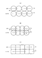
- a plurality of small electrodes 32 are arranged on the back surface of a thin film mirror (membrane) 35 that is a thin film-like reflecting surface, and the surface of the thin film mirror 35 is electrically attracted.
- the shape of the thin film mirror 35 is changed as illustrated by the reference numeral 36.
- the curved surface shape of the thin film mirror 35 is changed to make the beam diameter of the reflected light variable. Since the variable focus mirror can be miniaturized and has a high response speed, the operability is improved.
- FIG. 4A a plurality of small electrodes 32 are arranged on the back surface of a thin film mirror (membrane) 35 that is a thin film-like reflecting surface, and the surface of the thin film mirror 35 is electrically attracted.
- the shape of the thin film mirror 35 is changed as illustrated by the reference numeral 36.
- the electrode 32 is disposed on the substrate 31, and the thin film mirror 35 is held by the anchor 34 via the spacer 33 on the substrate 31.
- the arrangement of the electrodes 32 may be a honeycomb type having a plurality of electrodes 32a as shown in FIG. 4B or a coaxial type having a plurality of electrodes 32b as shown in FIG. 4C. May be.
- the light beam emitted with the beam diameter changed by the variable focus device 30 enters the MEMS mirror 14. Further, the light beam is projected onto the screen 15 by the biaxial MEMS mirror 14, and an image is formed on the screen 15 by a scanning method. The spot size of the light beam projected on the screen 15 is changed according to the projection size by the variable focus device 30 under the control of the control means, and the deterioration of the image quality is suppressed.
- the variable focus device 30 is driven by a control signal corresponding to the projection size obtained by the distance detection device 16 using infrared rays.
- variable focus mirror is normally controlled so as to change the position of the condensing point by changing the curvature, but by controlling each of the plurality of small electrodes 32 disposed on the back side of the thin film mirror 35. It can also be changed to a free curved surface shape. Therefore, the variable focus device 30 changes the reflecting surface of the thin film mirror 35 into a complicated shape according to the voltage pattern applied to the electrode 32, and changes the spot shape of the incident beam (cross-sectional shape is a circle) instead of a circle. It can also be deformed into a shape close to a square. As described above, the variable focus device 30 can control the spot shape on the screen 15 to be changed, for example, by changing the spot shape of the light beam on the screen 15 from a circular shape to a substantially square shape.
- FIG. 5A in the case of a circular spot Sc, a gap SS between the spots Sc is formed. If an attempt is made to fill the gap with the circular spot Sc, an overlapping portion D of the spots Sc is generated as shown in FIG. 5B, a difference from the non-overlapping portion is generated, and the image quality is deteriorated.
- FIG. 5C the gap between the pixels can be reduced and the overlapping portion can be reduced by changing the spot shape to a square (a square spot Sr). Image quality can be improved.
- the spot shape on the screen by using the variable focus mirror in the variable focus device. . Therefore, the degree of overlap between pixels can be made uniform, and the image quality can be further improved. In addition, since the drive voltage is relatively low, power consumption can be reduced and costs can be reduced. Further, by increasing the reflectance of the reflecting surface, the spot size can be controlled efficiently and a bright image can be obtained.
- variable focus device 30 may not be the electrostatic attraction type mentioned above.
- a piezo actuator type variable focus mirror may be used.
- a piezo actuator type variable focus mirror has a piezo actuator installed on the back of a thin film mirror and changes the shape of the mirror by expansion and contraction of the piezo. Therefore, the spot size of the light beam can be controlled by the voltage applied to the piezo.
- Piezo-actuator variable focus mirrors are inexpensive and can reduce costs.
- it since it is a reflection type variable focus device, it is not affected by the light absorption (transmittance) of a material such as a transmission type. Therefore, efficient spot size control can be performed by improving the reflectivity of the reflection surface. .
- the drive is performed even when the control voltage is relatively low, power consumption can be suppressed.
- FIG. 6 is a schematic plan view showing the internal configuration of an image display apparatus according to the fourth embodiment of the present invention.
- 6 is an image display apparatus.
- the same parts as those of the image display device 1 in the first embodiment are denoted by the same reference numerals, and a part of the description including application examples thereof will be omitted and briefly described. Note that the reduction in image quality degradation due to the projection size is the same as that described in the first embodiment.
- An image display device 6 illustrated in FIG. 6 includes a laser light source device 10 composed of R, G, and B laser light sources 10a to 10c, collimating lenses 11a to 11c that convert the output light rays into parallel light, Dichroic mirrors 12a to 12c that reflect only a wavelength, a variable focus device 60 that includes a plurality of lenses 61 to 63 and a lens moving mechanism, a MEMS mirror 14 that forms an image by a scanning method, a screen 15 that displays an image, and a screen 15 is configured by a distance detection device 16 that detects a distance from the distance 15.
- a laser light source device 10 composed of R, G, and B laser light sources 10a to 10c, collimating lenses 11a to 11c that convert the output light rays into parallel light, Dichroic mirrors 12a to 12c that reflect only a wavelength, a variable focus device 60 that includes a plurality of lenses 61 to 63 and a lens moving mechanism, a MEMS mirror 14 that forms an image by a scanning method,
- the image display device 6 converts the light beams emitted from the laser light sources R, G, and B into parallel light by the collimating lenses 11a to 11c.
- the parallel laser beams are combined into a bundle of beams by the dichroic mirrors 12a to 12c.
- the combined laser light is incident on the variable focus device 60 disposed on the optical path of the light beam.
- the beam diameter of the incident light beam is changed by the variable focus device 60.
- the variable focus device 60 in the present embodiment is configured by a combination of several lenses (lenses 61 to 63 in the example of FIG. 6), and some lenses (lenses 63 in the example of FIG. 6) are movable lenses such as actuators.
- the mechanism can be moved in the optical axis direction. By moving the lens, the condensing point of the light beam emitted from the laser light source is controlled, and the beam diameter of the emitted light beam can be changed.
- the light beam emitted with the beam diameter changed by the variable focus device 60 is incident on the MEMS mirror 14. Further, the light beam is projected onto the screen 15 by the biaxial MEMS mirror 14, and an image is formed on the screen 15 by a scanning method. The spot size of the light beam projected on the screen 15 is changed according to the projection size by the variable focus device 60 under the control of the control means, and the deterioration of the image quality is suppressed.
- the variable focus device 60 is driven by a control signal corresponding to the projection size obtained by the distance detection device 16 using infrared rays.
- the light beam whose beam diameter can be freely controlled is projected onto the screen 15 to form an image. Accordingly, in the present embodiment as well, as in the effects of the first to third embodiments, the light beam projected onto the screen 15 is controlled in the projection size because the light collection distance is controlled by the variable focus device 60. Accordingly, the spot size can be changed to optimize the image quality. Furthermore, in this embodiment, the spot size can be easily changed with simple mechanism parts, and an image can be formed without enlarging the beam diameter. Is possible.
- FIG. 7 is a diagram showing a control example of the image display apparatus according to the fifth embodiment of the present invention, in which 1, 2, 3 and 6 are the first, second, third and fourth implementations, respectively.
- 1 is an image display device according to an embodiment.
- the inclination of the screen 15 was explained without special consideration. Therefore, as shown in FIG. 7A, the screen 15a installed substantially parallel to the surface of the MEMS mirror 14 is projected in a rectangular shape like an image 72, but the tilted screen 15b is trapezoidal like an image 71. Will be projected.
- Such defects in the shape can be improved by correcting the shape by detecting the tilt of the screen 15 and controlling the laser beam accordingly. That is, as shown in FIG. 7B, the screen 15b tilted from the surface of the MEMS mirror 14 can be controlled to be projected into a rectangle like an image 73. When this control is performed, the screen 15a installed in parallel is projected into a trapezoid like an image 74.
- Detecting tilt can be realized by providing tilt detecting means in the control means.
- This inclination detecting means can calculate the inclination by geometric calculation by measuring the distance at a plurality of positions (preferably three or more positions) of the screen 15 with the aid of the distance detection device 16 described above. For example, the positional relationship of the range projected by the distance detection device 16 can be measured and obtained therefrom.
- the projection distance can be detected at least at two points such as one point on the scanning start line of the screen 15 and one point on the scanning end line, and the vertical inclination can be obtained.
- the projection distance can be detected at two different points in the horizontal direction, and the left / right inclination can be obtained.
- (I) As a method of controlling the laser light source, there is a method of changing the timing of turning on the laser in the laser light source device 10 while keeping the swing angle of the MEMS mirror 14 constant. That is, it is driven so as to gradually reduce the horizontal range to be lit as the lower side of the image is scanned, that is, to gradually illuminate only a portion having a small emission angle. Compared with the method (II) described below, this method does not dynamically control a movable device such as the MEMS mirror 14 and can therefore improve the life and the like.
- the spot size is gradually increased as the lower side is projected. It can be improved by controlling it to be smaller.
- the control means at this time may control the variable focus device 13 so as to change the spot size in the screen on the screen 15 according to the obtained inclination (angle of inclination) of the screen 15.
- the control means when the screen 15 is not directly facing (projected in parallel) and tilted, the control means always keeps changing the spot size dynamically while displaying an image.
- the spot size when facing directly, the spot size is basically controlled to be the optimum spot size, and thereafter, an image is displayed with a constant spot size.
- control means may directly control the variable focus device 13 so as to change the spot size according to the distance at the scanning point obtained from the distance detection device 16.
- control also corresponds to control for changing the spot size indirectly according to the inclination of the screen 15.
- the projection distance may be detected at two points of the scanning start point and the scanning end point of the screen 15, and the spot size may be determined and controlled based on the projection distance that interpolates these two points.
- the method of controlling the MEMS mirror 14 is a method of dynamically changing the swing angle of the MEMS mirror 14 itself. That is, control is performed so that the swing angle of the MEMS mirror 14 is reduced as the lower side of the screen is displayed.
- the screen 15b is tilted, so that the spot size is different for each portion of the screen and the image quality is deteriorated. Can be improved by dynamically controlling and correcting according to the inclination.
- the projection shape is corrected by controlling the laser beam, and the size of the beam diameter is adjusted by the control means and the variable focus device 13 to the projection position of the screen 15.
- the control means and the variable focus device 13 By variably controlling each time, it becomes possible to control the spot size according to the inclination of the screen 15, and an image with an optimum image quality can be obtained.
- the above (I) and (II) have been described on the premise that the light beam is not parallel light. However, when the emitted light is parallel light, the image quality varies depending on the projection size, and thus the parallel light is used. Even in this case, the spot size may be adjusted.
- the control unit controls the variable focus device so as to change the spot size according to the projection size.
- the image display device according to the sixth embodiment Instead of the projection size (projection distance) or as a fine adjustment after the control by the projection size, the variable focus device is controlled according to the user operation.
- control unit of the image display apparatus has an operation unit that receives a user operation for changing the spot size, and changes the spot size according to the user operation received by the operation unit.
- control the variable focus device Such an operation means, that is, a user interface may be mounted so as to be included in the image display device by providing an adjustment lever, an adjustment knob, or a television or a PC partially connected to the image display device. A user operation may be performed on the video source side and the operation signal may be received.
- this image display apparatus can be made highly versatile.
- the degree of overlap between pixels varies depending on the spot size
- the resolution of the image quality felt by the viewer who is the user varies. That is, sharp image quality is obtained when there is little overlap, and sharpness disappears as the overlap increases.
- the overlapping degree can be adjusted by the user. Therefore, in this embodiment, the resolution of the image can be adjusted to the user's preference, and as a result, the image quality can be adjusted to the user's preference.
- each embodiment of the present invention has been described on the premise that scanning is performed after combining RGB.
- a variable focus device and a MEMS mirror are provided for each of RGB and combined after scanning (for example, on a screen).
- a configuration may be employed. In that case, since the color for each pixel is expressed by the overlap of RGB rays, the pitch and beam diameter between RGB need to be the same in order to maintain the image quality.
Abstract
L'invention porte sur un dispositif d'affichage d'image qui peut réduire l'effet d'une dégradation de qualité d'image provoquée par une dimension de point sur un écran, dégradation générée lors de l'utilisation d'une source de lumière ayant une forte directivité telle qu'un faisceau laser et des moyens de formation d'image de type à balayage. Le dispositif d'affichage d'image comprend : un dispositif de source de lumière (10) qui émet de la lumière ; des moyens de formation d'image de type à balayage (tel qu'un miroir MEMS (14)) qui forment une image sur un écran (15) ; un dispositif à point focal variable (13) agencé dans le trajet optique de la lumière émise par le dispositif de source de lumière (10) pour atteindre les moyens de formation d'image ; et des moyens de commande qui commandent le dispositif à point focal variable (13) de façon à modifier la dimension du point lumineux projeté sur l'écran (15) conformément à une dimension de projection d'image ou une opération d'utilisateur.
Priority Applications (1)
| Application Number | Priority Date | Filing Date | Title |
|---|---|---|---|
| US12/918,021 US20100315605A1 (en) | 2008-02-18 | 2009-02-16 | Image display apparatus |
Applications Claiming Priority (2)
| Application Number | Priority Date | Filing Date | Title |
|---|---|---|---|
| JP2008036182A JP2009193008A (ja) | 2008-02-18 | 2008-02-18 | 画像表示装置 |
| JP2008-036182 | 2008-02-18 |
Publications (1)
| Publication Number | Publication Date |
|---|---|
| WO2009104524A1 true WO2009104524A1 (fr) | 2009-08-27 |
Family
ID=40985405
Family Applications (1)
| Application Number | Title | Priority Date | Filing Date |
|---|---|---|---|
| PCT/JP2009/052460 WO2009104524A1 (fr) | 2008-02-18 | 2009-02-16 | Dispositif d'affichage d'image |
Country Status (3)
| Country | Link |
|---|---|
| US (1) | US20100315605A1 (fr) |
| JP (1) | JP2009193008A (fr) |
| WO (1) | WO2009104524A1 (fr) |
Cited By (2)
| Publication number | Priority date | Publication date | Assignee | Title |
|---|---|---|---|---|
| JP2014085605A (ja) * | 2012-10-26 | 2014-05-12 | Hitachi Media Electoronics Co Ltd | レーザビーム表示装置並びにそのミラー制御方法 |
| CN104111528A (zh) * | 2014-06-23 | 2014-10-22 | 武汉市安曼特微显示科技有限公司 | 单灯投影机照明装置自由切换控制系统 |
Families Citing this family (45)
| Publication number | Priority date | Publication date | Assignee | Title |
|---|---|---|---|---|
| US8251517B2 (en) * | 2007-12-05 | 2012-08-28 | Microvision, Inc. | Scanned proximity detection method and apparatus for a scanned image projection system |
| IL192583A (en) * | 2008-07-02 | 2014-01-30 | Btendo Ltd | A mems device that includes a means for measuring oscillations |
| US20120113397A1 (en) * | 2009-04-21 | 2012-05-10 | Yusuke Hirao | Scanning Optical System and Projector Provided with the Same |
| WO2011012168A1 (fr) * | 2009-07-31 | 2011-02-03 | Lemoptix Sa | Système de microprojection optique et procédé de projection |
| WO2011046035A1 (fr) * | 2009-10-15 | 2011-04-21 | 日本電気株式会社 | Dispositif et procédé de projection d'image, dispositif et procédé de mesure de la distance |
| TWI396893B (zh) * | 2009-10-22 | 2013-05-21 | Univ Nat Chiao Tung | 光電裝置 |
| JP5488803B2 (ja) * | 2010-01-07 | 2014-05-14 | 株式会社リコー | 光学装置、該光学装置を有する投影型画像表示装置および光学装置の製造方法 |
| JP5701573B2 (ja) * | 2010-06-15 | 2015-04-15 | オリンパス株式会社 | スキャナ、走査型照明装置および走査型観察装置 |
| JP5803184B2 (ja) * | 2010-11-19 | 2015-11-04 | 株式会社リコー | 画像投影装置、メモリアクセス方法 |
| US9188846B2 (en) | 2011-02-18 | 2015-11-17 | Nec Corporation | Scanning-type image display device and its image display method |
| WO2012137305A1 (fr) * | 2011-04-05 | 2012-10-11 | Necディスプレイソリューションズ株式会社 | Dispositif de source de lumière et dispositif d'affichage à projection |
| JP5758717B2 (ja) * | 2011-06-22 | 2015-08-05 | スタンレー電気株式会社 | 車両用照明装置 |
| WO2013046904A1 (fr) * | 2011-09-27 | 2013-04-04 | 日本電気株式会社 | Dispositif de balayage optique, dispositif d'affichage d'image et procédé d'ajustement de zone de projection |
| JP2013125166A (ja) | 2011-12-15 | 2013-06-24 | Seiko Epson Corp | 照明装置 |
| JP5832919B2 (ja) | 2012-02-08 | 2015-12-16 | 日立マクセル株式会社 | レーザープロジェクター |
| DE102012202026A1 (de) * | 2012-02-10 | 2013-08-14 | Robert Bosch Gmbh | Projektionsvorrichtung und Verfahren zum Betreiben einer Projektionsvorrichtung |
| WO2013160982A1 (fr) * | 2012-04-23 | 2013-10-31 | パイオニア株式会社 | Appareil de génération d'image |
| US9846353B2 (en) * | 2012-06-01 | 2017-12-19 | Intel Corporation | Projection device combining and modifing light beam cross sectional dimensions |
| US9348138B2 (en) * | 2012-06-15 | 2016-05-24 | Mitsubishi Electric Corporation | Laser processing device |
| JP2014029395A (ja) * | 2012-07-31 | 2014-02-13 | Hitachi Media Electoronics Co Ltd | 光束走査装置、及び光束走査型画像映写装置 |
| JP6089551B2 (ja) | 2012-10-09 | 2017-03-08 | セイコーエプソン株式会社 | 照明装置 |
| CN103869584B (zh) * | 2012-12-12 | 2016-06-15 | 光宝科技股份有限公司 | 应用于投影装置的光机模块 |
| CN104884995B (zh) * | 2012-12-26 | 2017-10-03 | 西铁城时计株式会社 | 投影装置 |
| JP5729522B2 (ja) * | 2013-03-06 | 2015-06-03 | ウシオ電機株式会社 | 光源装置およびプロジェクタ |
| JP6100080B2 (ja) * | 2013-05-08 | 2017-03-22 | 株式会社東芝 | プロジェクタ及び携帯端末 |
| JP2015034919A (ja) * | 2013-08-09 | 2015-02-19 | 株式会社デンソー | 情報表示装置 |
| JP6053171B2 (ja) * | 2013-10-18 | 2016-12-27 | 増田 麻言 | 走査型投影装置、および携帯型投影装置 |
| KR102135356B1 (ko) * | 2013-10-24 | 2020-07-17 | 엘지전자 주식회사 | 영상투사장치 |
| JP6281174B2 (ja) * | 2014-03-25 | 2018-02-21 | スタンレー電気株式会社 | 車両用灯具及び結合分配器 |
| TWI588535B (zh) * | 2014-11-20 | 2017-06-21 | 英特爾股份有限公司 | 可調式焦距平面光學系統 |
| TWI688789B (zh) * | 2014-11-20 | 2020-03-21 | 美商英特爾股份有限公司 | 虛擬影像產生器及投影虛擬影像的方法 |
| WO2016121534A1 (fr) * | 2015-01-29 | 2016-08-04 | アルプス電気株式会社 | Afficheur |
| US10670857B2 (en) * | 2015-02-13 | 2020-06-02 | Nec Corporation | Projection device and interface device having mirror which reflects light other than zero-order light toward a projection lens |
| DE102015209418A1 (de) * | 2015-05-22 | 2016-11-24 | Robert Bosch Gmbh | Scanvorrichtung und Scanverfahren |
| JP6516223B2 (ja) * | 2015-06-30 | 2019-05-22 | パナソニックIpマネジメント株式会社 | 表示装置 |
| KR20170079355A (ko) * | 2015-12-30 | 2017-07-10 | 엘지이노텍 주식회사 | 발광 장치, 이 장치를 포함하는 광학 모듈, 및 이 모듈을 포함하는 차량 |
| US10962764B2 (en) * | 2016-04-01 | 2021-03-30 | Intel Corporation | Laser projector and camera |
| DE102016205413A1 (de) * | 2016-04-01 | 2017-10-05 | Robert Bosch Gmbh | Projektionseinrichtung und Verfahren zum Projizieren einer Bildinformation auf eine Projektionsfläche |
| JP6680109B2 (ja) * | 2016-06-28 | 2020-04-15 | 株式会社デンソー | 映像投射装置及びそれを備えるヘッドアップディスプレイ装置 |
| US10239178B2 (en) | 2016-10-17 | 2019-03-26 | Virtek Vision International, ULC | Laser projector with dynamically adaptable focus |
| GB2565834B (en) * | 2017-08-25 | 2020-05-20 | Dualitas Ltd | Display system |
| WO2020148580A1 (fr) * | 2019-01-18 | 2020-07-23 | Alcon Inc. | Commande de la position du point focal d'un faisceau laser |
| US11366309B2 (en) * | 2019-03-29 | 2022-06-21 | Facebook Technologies, Llc | Scanning projector display with multiple light engines |
| US11714282B2 (en) | 2019-03-29 | 2023-08-01 | Meta Platforms Technologies, Llc | Compact array light source for scanning display |
| CN112882230B (zh) * | 2019-11-29 | 2023-05-26 | 宁波舜宇车载光学技术有限公司 | 光学系统及消除色边的方法 |
Citations (4)
| Publication number | Priority date | Publication date | Assignee | Title |
|---|---|---|---|---|
| JP2002055297A (ja) * | 2000-08-11 | 2002-02-20 | Ngk Insulators Ltd | レーザビーム出力装置 |
| JP2002244063A (ja) * | 2001-02-20 | 2002-08-28 | Ricoh Co Ltd | レーザ光走査装置 |
| JP2003255263A (ja) * | 2001-12-25 | 2003-09-10 | Ricoh Co Ltd | 画像表示装置と画像表示方法 |
| JP2005259128A (ja) * | 2004-03-11 | 2005-09-22 | Symbol Technologies Inc | 電気光学読取装置の作動範囲及び性能を増大する光学的調節 |
Family Cites Families (4)
| Publication number | Priority date | Publication date | Assignee | Title |
|---|---|---|---|---|
| US7446822B2 (en) * | 2002-05-15 | 2008-11-04 | Symbol Technologies, Inc. | High-resolution image projection |
| JP4020043B2 (ja) * | 2003-08-25 | 2007-12-12 | カシオ計算機株式会社 | 投影装置、投影方法及びプログラム |
| US7771058B2 (en) * | 2005-04-22 | 2010-08-10 | Panasonic Corporation | Projection display apparatus |
| JP4750626B2 (ja) * | 2006-05-31 | 2011-08-17 | シチズンホールディングス株式会社 | 自動合焦点装置 |
-
2008
- 2008-02-18 JP JP2008036182A patent/JP2009193008A/ja active Pending
-
2009
- 2009-02-16 WO PCT/JP2009/052460 patent/WO2009104524A1/fr active Application Filing
- 2009-02-16 US US12/918,021 patent/US20100315605A1/en not_active Abandoned
Patent Citations (4)
| Publication number | Priority date | Publication date | Assignee | Title |
|---|---|---|---|---|
| JP2002055297A (ja) * | 2000-08-11 | 2002-02-20 | Ngk Insulators Ltd | レーザビーム出力装置 |
| JP2002244063A (ja) * | 2001-02-20 | 2002-08-28 | Ricoh Co Ltd | レーザ光走査装置 |
| JP2003255263A (ja) * | 2001-12-25 | 2003-09-10 | Ricoh Co Ltd | 画像表示装置と画像表示方法 |
| JP2005259128A (ja) * | 2004-03-11 | 2005-09-22 | Symbol Technologies Inc | 電気光学読取装置の作動範囲及び性能を増大する光学的調節 |
Cited By (2)
| Publication number | Priority date | Publication date | Assignee | Title |
|---|---|---|---|---|
| JP2014085605A (ja) * | 2012-10-26 | 2014-05-12 | Hitachi Media Electoronics Co Ltd | レーザビーム表示装置並びにそのミラー制御方法 |
| CN104111528A (zh) * | 2014-06-23 | 2014-10-22 | 武汉市安曼特微显示科技有限公司 | 单灯投影机照明装置自由切换控制系统 |
Also Published As
| Publication number | Publication date |
|---|---|
| JP2009193008A (ja) | 2009-08-27 |
| US20100315605A1 (en) | 2010-12-16 |
Similar Documents
| Publication | Publication Date | Title |
|---|---|---|
| WO2009104524A1 (fr) | Dispositif d'affichage d'image | |
| US7972011B2 (en) | Image projection apparatus and image projection system having beam deflection section | |
| US7677736B2 (en) | Illumination light source and two-dimensional image display using same | |
| US7021765B2 (en) | Illumination optical system and projection display optical system | |
| RU2464603C1 (ru) | Блок оптического сканирования, проектор изображений, включающий в себя его, автомобильное устройство отображения на ветровом стекле и мобильный телефон | |
| US7401927B2 (en) | Method of illumination and display apparatus | |
| JP2008509448A (ja) | 2次元画像投影システム | |
| WO2012111698A1 (fr) | Dispositif d'affichage d'images de balayage et procédé d'affichage d'images associé | |
| US7614752B2 (en) | Image display apparatus and method, and driving apparatus and method | |
| WO2015044995A1 (fr) | Afficheur | |
| US8264636B2 (en) | Laser backside irradiation device and liquid crystal display device | |
| JP4144713B2 (ja) | 投写型表示装置 | |
| US20070041077A1 (en) | Pocket-sized two-dimensional image projection system | |
| US9354503B2 (en) | Laser projector | |
| JP2009157111A (ja) | 画像表示装置 | |
| JP2007121539A (ja) | 画像表示装置 | |
| TW200909975A (en) | Device and method for compensating at least one non-linearity and laser projection system | |
| JP2011095291A (ja) | プロジェクター | |
| KR100201827B1 (ko) | 광로 조절 장치의 투사 시스템 | |
| JP2007079087A (ja) | 画像表示装置及び画像表示装置の制御方法 | |
| JP2014085605A (ja) | レーザビーム表示装置並びにそのミラー制御方法 | |
| JP2007121802A (ja) | 画像表示装置及び画像表示方法 | |
| KR100208662B1 (ko) | 투사형 화상 표시장치 및 이를 이용한 투사 방법 | |
| CN116449633A (zh) | 带光调制部件和扫描振镜部件的投影光机及投影仪 | |
| KR100208661B1 (ko) | 광학적 투사 시스템 및 이를 이용한 광 투사 방법 |
Legal Events
| Date | Code | Title | Description |
|---|---|---|---|
| 121 | Ep: the epo has been informed by wipo that ep was designated in this application |
Ref document number: 09712626 Country of ref document: EP Kind code of ref document: A1 |
|
| DPE1 | Request for preliminary examination filed after expiration of 19th month from priority date (pct application filed from 20040101) | ||
| WWE | Wipo information: entry into national phase |
Ref document number: 12918021 Country of ref document: US |
|
| NENP | Non-entry into the national phase |
Ref country code: DE |
|
| 122 | Ep: pct application non-entry in european phase |
Ref document number: 09712626 Country of ref document: EP Kind code of ref document: A1 |