WO2009104524A1 - Image display device - Google Patents
Image display device Download PDFInfo
- Publication number
- WO2009104524A1 WO2009104524A1 PCT/JP2009/052460 JP2009052460W WO2009104524A1 WO 2009104524 A1 WO2009104524 A1 WO 2009104524A1 JP 2009052460 W JP2009052460 W JP 2009052460W WO 2009104524 A1 WO2009104524 A1 WO 2009104524A1
- Authority
- WO
- WIPO (PCT)
- Prior art keywords
- variable focus
- screen
- image display
- size
- spot size
- Prior art date
Links
Images


Classifications
-
- H—ELECTRICITY
- H04—ELECTRIC COMMUNICATION TECHNIQUE
- H04N—PICTORIAL COMMUNICATION, e.g. TELEVISION
- H04N9/00—Details of colour television systems
- H04N9/12—Picture reproducers
- H04N9/31—Projection devices for colour picture display, e.g. using electronic spatial light modulators [ESLM]
- H04N9/3141—Constructional details thereof
- H04N9/317—Convergence or focusing systems
-
- G—PHYSICS
- G02—OPTICS
- G02B—OPTICAL ELEMENTS, SYSTEMS OR APPARATUS
- G02B26/00—Optical devices or arrangements for the control of light using movable or deformable optical elements
- G02B26/08—Optical devices or arrangements for the control of light using movable or deformable optical elements for controlling the direction of light
- G02B26/0816—Optical devices or arrangements for the control of light using movable or deformable optical elements for controlling the direction of light by means of one or more reflecting elements
-
- G—PHYSICS
- G02—OPTICS
- G02B—OPTICAL ELEMENTS, SYSTEMS OR APPARATUS
- G02B26/00—Optical devices or arrangements for the control of light using movable or deformable optical elements
- G02B26/08—Optical devices or arrangements for the control of light using movable or deformable optical elements for controlling the direction of light
- G02B26/0875—Optical devices or arrangements for the control of light using movable or deformable optical elements for controlling the direction of light by means of one or more refracting elements
-
- G—PHYSICS
- G02—OPTICS
- G02B—OPTICAL ELEMENTS, SYSTEMS OR APPARATUS
- G02B3/00—Simple or compound lenses
- G02B3/12—Fluid-filled or evacuated lenses
- G02B3/14—Fluid-filled or evacuated lenses of variable focal length
-
- G—PHYSICS
- G03—PHOTOGRAPHY; CINEMATOGRAPHY; ANALOGOUS TECHNIQUES USING WAVES OTHER THAN OPTICAL WAVES; ELECTROGRAPHY; HOLOGRAPHY
- G03B—APPARATUS OR ARRANGEMENTS FOR TAKING PHOTOGRAPHS OR FOR PROJECTING OR VIEWING THEM; APPARATUS OR ARRANGEMENTS EMPLOYING ANALOGOUS TECHNIQUES USING WAVES OTHER THAN OPTICAL WAVES; ACCESSORIES THEREFOR
- G03B21/00—Projectors or projection-type viewers; Accessories therefor
- G03B21/005—Projectors using an electronic spatial light modulator but not peculiar thereto
-
- H—ELECTRICITY
- H04—ELECTRIC COMMUNICATION TECHNIQUE
- H04N—PICTORIAL COMMUNICATION, e.g. TELEVISION
- H04N9/00—Details of colour television systems
- H04N9/12—Picture reproducers
- H04N9/31—Projection devices for colour picture display, e.g. using electronic spatial light modulators [ESLM]
- H04N9/3129—Projection devices for colour picture display, e.g. using electronic spatial light modulators [ESLM] scanning a light beam on the display screen
Abstract
Provided is an image display device which can reduce the affect of image quality degradation caused by a spot size on a screen generated when using a light source having a strong directivity such as a laser beam and scan-type image formation means. The image display device includes: a light source device (10) which emits light; scan-type image formation means (such as an MEMS mirror (14)) which forms an image on a screen (15); a variable focal point device (13) arranged in the optical path of the light emitted from the light source device (10) to reach the image formation means; and control means which controls the variable focal point device (13) so as to modify the size of the light spot projected onto the screen (15) in accordance with an image projection size or an user operation.
Description
本発明は、画像表示装置に関し、より詳細には、レーザ光等の指向性の強い光源を用いた画像表示装置に関する。
The present invention relates to an image display device, and more particularly, to an image display device using a light source with strong directivity such as laser light.
光源装置からの光を液晶パネルのような空間光変調素子に照射し、スクリーンに投影させることにより画像表示を行うプロジェクタ(投影型画像表示装置)がある。従来、投影型画像表示装置の光源として高圧水銀ランプやメタルハライドランプといったランプが使用されてきた。
There is a projector (projection-type image display device) that displays an image by irradiating light from a light source device onto a spatial light modulation element such as a liquid crystal panel and projecting it on a screen. Conventionally, lamps such as high-pressure mercury lamps and metal halide lamps have been used as light sources for projection-type image display devices.
しかしながら、このようなランプは、寿命が短く点灯に時間がかかるという課題があるだけでなく、光源から赤、緑、青の3原色に分光するための光学系が必要であり、光利用効率低減や構造の複雑化、色再現性が課題となっている。
However, such a lamp not only has a problem that it has a short lifetime and takes a long time to light, but also requires an optical system for splitting light from the light source into the three primary colors of red, green, and blue, reducing the light utilization efficiency. The complexity of the structure and the color reproducibility are issues.
このような課題を解決するために、近年ではレーザ光を用いた画像表示装置が提案されている。レーザを光源とすることで、長寿命化、広色域化、光利用効率がよいことによる消費電力低減、光学系の単純化に伴う小型化など多数の改善が期待できる。
In order to solve such problems, in recent years, an image display device using laser light has been proposed. By using a laser as a light source, a number of improvements can be expected such as longer life, wider color gamut, reduced power consumption due to good light utilization efficiency, and downsizing due to simplification of the optical system.
例えば、特許文献1にはレーザを光源とした投影型画像表示装置が開示されている。この投影型画像表示装置は、光源部が赤、緑、青の3つの波長を出射するレーザ光源装置により構成されており、それぞれのレーザから出射された光線は適度な拡がりまで拡散された後、合成されて空間変調素子である液晶パネルへと入射される。そして、液晶パネルへと入射した光は画像信号に応じて変調されて投影レンズによりスクリーンへ投射されてスクリーン上に画像を形成する。
For example, Patent Document 1 discloses a projection type image display apparatus using a laser as a light source. This projection type image display device is composed of a laser light source device in which the light source unit emits three wavelengths of red, green, and blue, and after the light beams emitted from the respective lasers are diffused to an appropriate spread, The combined light is incident on a liquid crystal panel, which is a spatial modulation element. The light incident on the liquid crystal panel is modulated in accordance with the image signal and projected onto the screen by the projection lens to form an image on the screen.
このような空間変調素子を用いた投影型画像表示装置では空間変調素子のサイズまでビーム径を拡大する必要があることと、素子面内で光の均一化をする必要があるためフライアイレンズや光インテグレータ等の機構が必要になり、小型化が困難である。そのため、レーザ光源と走査型の画像形成装置とを組み合わせることで小型化を行う研究も行われており、そのようなレーザを光源とした走査型の画像表示装置もいくつか提案されている。
In the projection type image display apparatus using such a spatial modulation element, it is necessary to expand the beam diameter to the size of the spatial modulation element, and it is necessary to make the light uniform in the element plane. A mechanism such as an optical integrator is required, and miniaturization is difficult. For this reason, research has been conducted to reduce the size by combining a laser light source and a scanning image forming apparatus, and several scanning image display apparatuses using such a laser as a light source have been proposed.
特許文献2には、レーザ光源と走査型画像形成手段により画像を形成する投影型画像表示装置が開示されている。この投射型画像表示装置では、光源部にレーザを用い、赤、緑、青色の波長の光線を発生させ、合成した後、走査型の画像形成手段によりスクリーン上に出射された光線を水平、垂直方向へ光速に移動させてスクリーン上に画像を形成する。この投射型画像表示装置では、レーザ光線のビーム径を拡大せずにスクリーンまで到達させるため、光学部品が小型化できる。
特開2000-131762号公報
特開平7-067064号公報
Patent Document 2 discloses a projection type image display apparatus that forms an image with a laser light source and scanning image forming means. In this projection type image display device, a laser is used for the light source unit, and light beams of red, green and blue wavelengths are generated and synthesized, and then the light beams emitted on the screen by the scanning image forming means are horizontally and vertically aligned. An image is formed on the screen by moving in the direction of light speed. In this projection type image display device, the optical component can be reduced in size because it reaches the screen without enlarging the beam diameter of the laser beam.
JP 2000-131762 A JP-A-7-066704
特許文献2に記載のごとく、レーザ光源と走査型画像形成手段を用いた投影型画像表示装置では、スクリーンへ到達した光線のスポットサイズが画像の1画素の大きさに対応する。従って、スクリーン上のスポットサイズによって隣接画素との重なる程度が変わるため画質に大きな影響を与える。例えば、画像表示装置より出射される光線が拡がりを持たず一定の場合、或る一定の投影サイズではスポットサイズが最適であっても、それより大きなサイズで投影した場合には上下のスポット間で隙間ができるため画質が劣化する。また、スクリーンを近づけ、投影サイズを小さくした場合、スポット同士の重なりが大きくなるため解像感が低下し、画質は劣化する。
As described in Patent Document 2, in the projection type image display apparatus using the laser light source and the scanning type image forming means, the spot size of the light beam reaching the screen corresponds to the size of one pixel of the image. Accordingly, the degree of overlapping with adjacent pixels varies depending on the spot size on the screen, which greatly affects image quality. For example, when the light beam emitted from the image display device is constant without spreading, even if the spot size is optimal for a certain projection size, but when projected with a larger size, it is between the upper and lower spots. Since there is a gap, the image quality deteriorates. In addition, when the screen is brought closer and the projection size is reduced, the overlap between spots is increased, so that the resolution is lowered and the image quality is deteriorated.
このように、レーザ光源と走査型画像形成手段を用いた従来の投影型画像表示装置では、画像表示装置から出射される光線の拡がりが一定であり、投影する画像サイズが変わると良好な画質を保つことができない。また、どのような投影サイズであっても良好な画質を保つためには、投影する画像サイズに応じてスクリーン上での光線のスポットサイズを変える必要があるが、従来、このような検討はなされていない。
As described above, in the conventional projection type image display device using the laser light source and the scanning type image forming means, the spread of the light beam emitted from the image display device is constant, and a good image quality is obtained when the projected image size changes. I can't keep it. Also, in order to maintain good image quality regardless of the projection size, it is necessary to change the spot size of the light beam on the screen according to the image size to be projected. Not.
また、レーザ光源と走査型画像形成手段を用いた従来の投影型画像表示装置では、ユーザの好みに応じて画質を変えるといった検討もなされていない。
Further, in the conventional projection type image display apparatus using the laser light source and the scanning type image forming means, there has been no examination of changing the image quality according to the user's preference.
本発明は、斯かる事情に鑑みてなされたものであり、レーザ光等の強い指向性をもった光源と走査型の画像形成手段を用いる場合に生じるスクリーン上のスポットサイズによる画質劣化の影響を低減するために、画像の投影サイズ又はユーザ操作に応じてスクリーン上のスポットサイズを制御することが可能な画像表示装置を提供することを、その目的とする。
The present invention has been made in view of such circumstances, and has the effect of image quality deterioration due to the spot size on the screen that occurs when a light source having a strong directivity such as laser light and a scanning image forming means are used. An object of the present invention is to provide an image display device capable of controlling the projected size of an image or the spot size on a screen in accordance with a user operation in order to reduce the size.
上述のごとき課題を解決するために、本発明の第1の技術手段は、光線を発する光源装置と、スクリーン上に画像を形成する走査型の画像形成手段と、前記光源装置から発せられた光線が該画像形成手段に到達するまでの光路中に配設された可変焦点装置と、前記スクリーンへ投射される光線のスポットサイズを変更するように、前記可変焦点装置を制御する制御手段とを備えたことを特徴としたものである。
In order to solve the above-described problems, the first technical means of the present invention includes a light source device that emits light, a scanning-type image forming device that forms an image on a screen, and a light beam emitted from the light source device. A variable focus device disposed in an optical path until the image forming means reaches the image forming means, and a control means for controlling the variable focus device so as to change the spot size of the light beam projected onto the screen. It is characterized by that.
第2の技術手段は、第1の技術手段において、前記制御手段は、投影サイズを検出する投影サイズ検出手段を有し、該投影サイズ検出手段で検出された投影サイズに応じて、前記スポットサイズを変更するように、前記可変焦点装置を制御することを特徴としたものである。
According to a second technical means, in the first technical means, the control means has a projection size detection means for detecting a projection size, and the spot size is determined according to the projection size detected by the projection size detection means. The varifocal device is controlled so as to change.
第3の技術手段は、第2の技術手段において、前記投影サイズ検出手段は、前記スクリーンまでの投影距離を検出する距離検出手段であり、前記制御手段は、前記距離検出手段で検出された投影距離に対応した投影サイズに応じて、前記スポットサイズを変更するように、前記可変焦点装置を制御することを特徴としたものである。
According to a third technical means, in the second technical means, the projection size detecting means is a distance detecting means for detecting a projection distance to the screen, and the control means is a projection detected by the distance detecting means. The variable focus apparatus is controlled so as to change the spot size according to a projection size corresponding to a distance.
第4の技術手段は、第1の技術手段において、前記制御手段は、前記スポットサイズを変更するユーザ操作を受け付ける操作手段を有し、該操作手段で受け付けたユーザ操作に応じた前記スポットサイズの変更を行うように、前記可変焦点装置を制御することを特徴としたものである。
According to a fourth technical means, in the first technical means, the control means has operation means for accepting a user operation for changing the spot size, and the spot size corresponding to the user operation accepted by the operation means. The variable focus device is controlled so as to make a change.
第5の技術手段は、第1~第4のいずれかの技術手段において、前記可変焦点装置は、前記スポットサイズを電気的に制御することが可能な素子を有することを特徴としたものである。
According to a fifth technical means, in any one of the first to fourth technical means, the variable focus device includes an element capable of electrically controlling the spot size. .
第6の技術手段は、第5の技術手段において、前記可変焦点装置は、前記素子として液晶レンズを有し、該液晶レンズへの印加電圧制御によって前記スポットサイズを変更することを特徴としたものである。
A sixth technical means is the fifth technical means, wherein the variable focus device has a liquid crystal lens as the element, and the spot size is changed by controlling an applied voltage to the liquid crystal lens. It is.
第7の技術手段は、第5の技術手段において、前記可変焦点装置は、前記素子として液体レンズを有し、該液体レンズの印加電圧制御によって前記スポットサイズを変更することを特徴としたものである。
A seventh technical means is the fifth technical means, wherein the variable focus device has a liquid lens as the element, and the spot size is changed by controlling an applied voltage of the liquid lens. is there.
第8の技術手段は、第5の技術手段において、前記可変焦点装置は、前記素子として、ミラーの曲面形状が可変である可変焦点ミラーを有し、該可変焦点ミラーへの印加電圧制御によって前記スポットサイズを変更することを特徴としたものである。
According to an eighth technical means, in the fifth technical means, the variable focus device has a variable focus mirror whose curved surface shape is variable as the element, and the voltage is controlled by controlling an applied voltage to the variable focus mirror. The spot size is changed.
第9の技術手段は、第8の技術手段において、前記可変焦点装置は、前記スクリーン上でのスポットの形状を略四角形となるよう制御することを特徴したものである。
Ninth technical means is characterized in that, in the eighth technical means, the variable focus device controls the shape of the spot on the screen to be substantially rectangular.
第10の技術手段は、第1~第4のいずれかの技術手段において、前記可変焦点装置は、複数枚のレンズと、該レンズの少なくとも1つを光軸方向に移動させるレンズ可動機構とを有し、該レンズ可動機構でレンズを移動させることによって前記スポットサイズを変更することを特徴としたものである。
In a tenth technical means according to any one of the first to fourth technical means, the variable focus device includes a plurality of lenses and a lens moving mechanism for moving at least one of the lenses in the optical axis direction. And the spot size is changed by moving the lens by the lens moving mechanism.
第11の技術手段は、第1~第10のいずれかの技術手段において、前記制御手段は、前記スクリーンの傾きを検出する傾き検出手段を有し、該傾き検出手段で検出された傾きに応じて、前記スクリーン上の画面内でスポットサイズを変更するように、前記可変焦点装置を制御することを特徴としたものである。
An eleventh technical means is any one of the first to tenth technical means, wherein the control means has an inclination detecting means for detecting an inclination of the screen, and is adapted to the inclination detected by the inclination detecting means. The variable focus device is controlled to change the spot size in the screen on the screen.
本発明の画像表示装置によれば、レーザ光等の強い指向性をもった光源と走査型の画像形成手段を用いる場合に生じるスクリーン上のスポットサイズによる画質劣化の影響を低減し、どのような投影サイズであっても同等の画質を得ること、或いはユーザが好む画質の投影画像を得ることが可能となる。
According to the image display device of the present invention, it is possible to reduce the influence of image quality deterioration due to the spot size on the screen that occurs when using a light source having a strong directivity such as laser light and a scanning image forming unit. Even with the projection size, it is possible to obtain the same image quality or to obtain a projection image having the image quality preferred by the user.
1,2,3,6…画像表示装置、10…レーザ光源装置、10a~10c…レーザ光源、11a~11c…コリメートレンズ、12a~12c…ダイクロイックミラー、13,20,30,60…可変焦点装置、14…MEMSミラー、15…スクリーン、16…距離検出装置。
1, 2, 3, 6 ... Image display device, 10 ... Laser light source device, 10a-10c ... Laser light source, 11a-11c ... Collimating lens, 12a-12c ... Dichroic mirror, 13, 20, 30, 60 ... Variable focus device , 14... MEMS mirror, 15... Screen, 16.
以下、本発明に係る画像表示装置について各実施形態を挙げ図面を参照しながら説明する。本発明に係る画像表示装置としてはプロジェクタが例示でき、特に、携帯電話機も含めてモバイル機器へ組み込むことでより効果が望める。実際、現状では携帯電話機等へ組み込みを考えて超小型のレーザプロジェクタの開発が盛んであるにも拘わらず、投影サイズによる画質低下の問題は殆ど解決できていない。本発明は、後述するように簡単な構成でどのような投影サイズであっても良好な画質を得ることが可能なため、モバイル機器のような小型の機器に特に有用となる。
Hereinafter, the image display apparatus according to the present invention will be described with reference to the drawings, citing each embodiment. As the image display apparatus according to the present invention, a projector can be exemplified, and in particular, the effect can be expected by being incorporated in a mobile device including a mobile phone. Actually, despite the fact that development of ultra-small laser projectors has been actively conducted in consideration of incorporation into mobile phones and the like, the problem of image quality degradation due to projection size has hardly been solved. The present invention is particularly useful for a small device such as a mobile device because a good image quality can be obtained at any projection size with a simple configuration as will be described later.
<第1の実施形態>
図1は、本発明の第1の実施形態に係る画像表示装置の構成例を示す図で、図中、1は画像表示装置である。 <First Embodiment>
FIG. 1 is a diagram illustrating a configuration example of an image display device according to a first embodiment of the present invention, in which 1 is an image display device.
図1は、本発明の第1の実施形態に係る画像表示装置の構成例を示す図で、図中、1は画像表示装置である。 <First Embodiment>
FIG. 1 is a diagram illustrating a configuration example of an image display device according to a first embodiment of the present invention, in which 1 is an image display device.
図1で例示する画像表示装置1は、R(赤)、G(緑)、B(青)のレーザ光源10a~10cによって構成されるレーザ光源装置10、出力された光線を平行光とするコリメートレンズ11a~11c、それぞれの光線の波長のみを反射するダイクロイックミラー12a~12c、可変焦点装置13、走査方式で画像を形成するMEMS(Micro Electro Mechanical Systems)ミラー14、画像を映し出すスクリーン15、及びスクリーン15までの距離を検出する距離検出装置16によって構成されている。可変焦点装置13は、レーザ光源装置10から発せられた光線がMEMSミラー14に到達するまでの光路中に配設されていればよい。
An image display device 1 illustrated in FIG. 1 includes a laser light source device 10 composed of R (red), G (green), and B (blue) laser light sources 10a to 10c, and a collimator that collimates the output light beam. Lenses 11a to 11c, dichroic mirrors 12a to 12c that reflect only the wavelengths of the respective rays, variable focus device 13, MEMS (Micro Electro Mechanical Systems) mirror 14 that forms an image by a scanning method, screen 15 that displays an image, and screen The distance detection device 16 detects a distance up to 15. The variable focus device 13 may be arranged in the optical path until the light beam emitted from the laser light source device 10 reaches the MEMS mirror 14.
レーザ光源装置10は、各色レーザ光源を例えば次のように構成すればよい。レーザ光源10aは赤色レーザ光を出射する半導体レーザとし、レーザ光源10bは半導体レーザと光導波路型SHG(Second Harmonic Generation)素子を組み合わせた緑色レーザ光を出射するレーザとし、レーザ光源10cは青色レーザ光を出射する半導体レーザ光源とする。レーザ光源装置10において、各レーザ光源10a~10cから発せられる光の強度は個別に制御される。
The laser light source device 10 may be configured as follows for each color laser light source, for example. The laser light source 10a is a semiconductor laser that emits red laser light, the laser light source 10b is a laser that emits green laser light that combines a semiconductor laser and an optical waveguide type SHG (Second Harmonic Generation) element, and the laser light source 10c is a blue laser light. Is a semiconductor laser light source that emits light. In the laser light source device 10, the intensity of light emitted from each of the laser light sources 10a to 10c is individually controlled.
なお、レーザ光源は固体レーザやガスレーザでもよく、レーザの波長や種類はここで示したものに限らない。また、複数個のレーザを組み合わせてもよく、その場合にはさらに強度の強いレーザ光を得ることができ、明るい画像を形成できる。また、半導体レーザはすでに量産化されている小型で高効率のレーザ光源であるので、コスト低減と共に装置の小型化と明るい画像表示が可能である。また、本発明では、レーザ光以外の光源であっても、レーザ光と同様に強い指向性をもつ光線(拡がらないで進む光線)を発する光源を採用してもよい。
The laser light source may be a solid laser or a gas laser, and the wavelength and type of the laser are not limited to those shown here. In addition, a plurality of lasers may be combined. In that case, a laser beam having a higher intensity can be obtained, and a bright image can be formed. Further, since the semiconductor laser is a small and highly efficient laser light source that has already been mass-produced, the cost can be reduced and the apparatus can be downsized and a bright image can be displayed. In the present invention, even a light source other than a laser beam, a light source that emits a light beam having a strong directivity (a beam that travels without spreading) as in the case of the laser beam may be employed.
R、G、Bのレーザ光源10a~10cから発せられた光線は、それぞれ、コリメートレンズ11a~11cよって平行光とされてダイクロイックミラー12a~12cに入射される。そして、ダイクロイックミラー12a~12cに入射した光線は1束の光線へと合成される。ダイクロイックミラー12a~12cはそれぞれ特定の波長のみ反射するミラーである。ダイクロイックミラー12aは赤色光線を、ダイクロイックミラー12bは緑色光線を、ダイクロイックミラー12cは青色光線を、それぞれ反射することで、レーザ光線を1束に合成する。合成にはダイクロイックミラーを用いたが、クロスプリズムなど他の手法を用いても構わない。
The light beams emitted from the R, G, and B laser light sources 10a to 10c are collimated by the collimating lenses 11a to 11c and are incident on the dichroic mirrors 12a to 12c, respectively. The light beams incident on the dichroic mirrors 12a to 12c are combined into a bundle of light beams. Each of the dichroic mirrors 12a to 12c is a mirror that reflects only a specific wavelength. The dichroic mirror 12a reflects the red light, the dichroic mirror 12b reflects the green light, and the dichroic mirror 12c reflects the blue light, thereby combining the laser beams into one bundle. A dichroic mirror is used for the composition, but other methods such as a cross prism may be used.
ダイクロイックミラー12a~12cによって合成された光線は、可変焦点装置13へと入射される。可変焦点装置13は液晶レンズを有し、液晶レンズへの印加電圧によって出射光線のビーム径を制御する。
The light beams synthesized by the dichroic mirrors 12 a to 12 c are incident on the variable focus device 13. The variable focus device 13 has a liquid crystal lens, and controls the beam diameter of the outgoing light beam by the voltage applied to the liquid crystal lens.
より具体的には、液晶レンズはガラス基盤と液晶層と電極によって構成され、ガラス基盤に挟まれた液晶層へ電界をかけることで液晶層の屈折率分布を変化させ、この屈折率分布を同心円状に勾配がつくようにすることでレンズと同等の働きを得ることができる。また、印加する電界の強さを制御することでこの屈折率変化の勾配を変化させ、液晶レンズを透過する光線の集光点を自由に制御できる。
More specifically, a liquid crystal lens is composed of a glass substrate, a liquid crystal layer, and an electrode, and changes the refractive index distribution of the liquid crystal layer by applying an electric field to the liquid crystal layer sandwiched between the glass substrates. The same function as a lens can be obtained by providing a gradient in the shape. Further, by controlling the strength of the applied electric field, the gradient of the refractive index change can be changed, and the condensing point of the light beam transmitted through the liquid crystal lens can be freely controlled.
本構成例で用いた液晶レンズは、2つのガラス基盤間に液晶層を配置し、ガラス基盤の片側にはアルミニウム薄膜等で構成された円形の孔を有する第1の電極とその孔部分に配置する円形状の第2の電極を備え、他方には第3の電極層を備えた構成をしている。第1の電極と第2の電極に異なる電界を印加することにより、第1の電極の中心軸に軸対称な電界勾配を形成し、この電界勾配方向に液晶分子が配向することで異常光の屈折率分布が軸対象に形成される。そのため、第1の電極の孔の中心を光軸としたレンズとしての効果を有する。ここで、円形電極2への印加電圧を変化させることで第1の電極と対向する第3の電極層の間に形成される電界勾配を変化させることができる。従って、第2の電極に印加する電界を制御することで自由に液晶レンズの焦点距離を変化させることが可能である。
The liquid crystal lens used in this configuration example has a liquid crystal layer disposed between two glass substrates, a first electrode having a circular hole formed of an aluminum thin film on one side of the glass substrate, and the hole portion. The circular second electrode is provided, and the other is provided with a third electrode layer. By applying different electric fields to the first electrode and the second electrode, an axially symmetric electric field gradient is formed on the central axis of the first electrode, and liquid crystal molecules are aligned in the electric field gradient direction, thereby causing abnormal light A refractive index distribution is formed on the axis object. Therefore, it has an effect as a lens having the center of the hole of the first electrode as the optical axis. Here, the electric field gradient formed between the third electrode layer facing the first electrode can be changed by changing the voltage applied to the circular electrode 2. Therefore, it is possible to freely change the focal length of the liquid crystal lens by controlling the electric field applied to the second electrode.
本実施形態での液晶レンズは、孔を有した電極を備えた構成として説明したが、これに限定するのではなく、液晶層に軸対象な電界分布を形成可能な電極構造であれば構わない。例えば、同心円状に配置された複数の円形電極を備え、それぞれの円形電極に異なる電圧を印加し、液晶層に軸対象な電界分布を形成したものでもよい。
The liquid crystal lens in the present embodiment has been described as a configuration including an electrode having a hole. However, the present invention is not limited to this, and any electrode structure capable of forming an axial electric field distribution in the liquid crystal layer may be used. . For example, a plurality of circular electrodes arranged concentrically may be provided, and different voltages may be applied to the respective circular electrodes to form an axial target electric field distribution in the liquid crystal layer.
また、液晶レンズは液晶層を含んでいることから偏光特性があり、偏光方向の合った光に対してのみレンズとしての機能を果たすことになる。そのため、本構成例ではレーザ光源装置10からの光線の偏光方向を液晶の偏光方向に合わせるように液晶レンズを配置し、効率良くビーム径の制御が行えるようにしている。本構成例とは異なり、光源装置から出射される光線の偏光方向が単一の方向でない場合は、液晶層を2層以上有し、そのうち1層以上の液晶層が偏光方向の異なる配置とした液晶レンズを用いることで全ての偏光方向に対応することができる。このとき、配光方向が垂直となるように液晶層を配置するのが望ましい。ただし、レーザ光の偏光方向を液晶の偏光特性と合わせる方が液晶レンズの構成が簡素化されること、並びにレーザ光の偏光制御自体が容易に行うことが可能であることから、レーザ光源装置10からの光線の偏光方向を液晶の偏光特性に合わせる方が好ましい。
In addition, since the liquid crystal lens includes a liquid crystal layer, it has a polarization characteristic and functions as a lens only for light having the same polarization direction. For this reason, in this configuration example, a liquid crystal lens is arranged so that the polarization direction of the light beam from the laser light source device 10 matches the polarization direction of the liquid crystal so that the beam diameter can be controlled efficiently. Unlike this configuration example, when the polarization direction of the light emitted from the light source device is not a single direction, it has two or more liquid crystal layers, and one or more of the liquid crystal layers are arranged in different polarization directions. By using a liquid crystal lens, all polarization directions can be handled. At this time, it is desirable to dispose the liquid crystal layer so that the light distribution direction is vertical. However, since the configuration of the liquid crystal lens can be simplified by matching the polarization direction of the laser light with the polarization characteristics of the liquid crystal, and the polarization control of the laser light itself can be easily performed, the laser light source device 10. It is preferable to match the polarization direction of the light from the liquid crystal with the polarization characteristics of the liquid crystal.
可変焦点装置13から出射された光線はMEMSミラー14へ照射され、走査方式によってスクリーン15に画像を形成する。MEMSミラー14は、アクチュエータとマイクロミラーによって構成される2軸のMEMSミラーであり、X方向(横方向)とY方向(縦方向)にマイクロミラーの角度を制御する。マイクロミラーに入射した光線はスクリーン15上を走査するように反射される(図1のスクリーン15上の点線を参照)。この時、RGBレーザ光の色や強度を個別に変調して制御しているので、映像の各画素に対して、MEMSミラー14から出射される光の色と強度を制御してスクリーン15に投影し、CRT(Cathode-ray Tube)ディスプレイのように高速で走査することで画像を形成する。このようにレーザ光線をスクリーン上で走査することで画像を形成し、且つスクリーン上のスポットサイズを自由に変化させることができるので、装置内部ではレーザ光源から発せられた光線のビーム径(照射スポット径)を可能な限り小さくしたまま処理できる。そのため、装置や光学部材の小型化が可能であり、さらには価格を低減させることができる。
The light beam emitted from the variable focus device 13 is applied to the MEMS mirror 14 to form an image on the screen 15 by a scanning method. The MEMS mirror 14 is a biaxial MEMS mirror composed of an actuator and a micromirror, and controls the angle of the micromirror in the X direction (lateral direction) and the Y direction (vertical direction). The light beam incident on the micromirror is reflected so as to scan on the screen 15 (see the dotted line on the screen 15 in FIG. 1). At this time, since the color and intensity of the RGB laser light are individually modulated and controlled, the color and intensity of the light emitted from the MEMS mirror 14 is controlled and projected onto the screen 15 for each pixel of the image. Then, an image is formed by scanning at a high speed like a CRT (Cathode-ray Tube) display. By scanning the laser beam on the screen in this way, an image can be formed and the spot size on the screen can be freely changed. Therefore, the beam diameter of the light beam emitted from the laser light source (irradiation spot) is set inside the apparatus. (Diameter) can be processed as small as possible. Therefore, it is possible to reduce the size of the device and the optical member, and it is possible to reduce the price.
また、本実施形態ではMEMSミラー14に2軸のMEMSミラーを用いたが、1軸のMEMSミラーを2個組み合わせても構わない。この場合、1つは横方向の走査を行い、他方は縦方向の走査を行うことで2次元画像を得ることができる。また、MEMSミラー14の代わりに、他の走査型画像形成手段を設けてもよい。
In this embodiment, a biaxial MEMS mirror is used as the MEMS mirror 14, but two uniaxial MEMS mirrors may be combined. In this case, a two-dimensional image can be obtained by scanning one in the horizontal direction and scanning the other in the vertical direction. Further, instead of the MEMS mirror 14, other scanning image forming means may be provided.
そして、上述のごとく液晶レンズを備えた可変焦点装置13によってビーム径を制御しているため、スクリーン15に照射された光線のスポットSのサイズ(スポットサイズ)はそのビーム径に応じて変更されることになる。このように、液晶レンズは、スポットサイズを電気的に制御することが可能な素子の一例である。
Since the beam diameter is controlled by the variable focus device 13 having the liquid crystal lens as described above, the size (spot size) of the spot S of the light beam irradiated on the screen 15 is changed according to the beam diameter. It will be. Thus, the liquid crystal lens is an example of an element that can electrically control the spot size.
可変焦点装置13に対する制御は、画像表示装置1に制御手段を備えておけばよい。この制御手段は、投影サイズに応じて、スクリーン15へ投射される光線のスポットサイズを変更するように、可変焦点装置13を制御する手段である。投影サイズを検出する手段(投影サイズ検出手段)は、カメラなどを用いて実際に画面サイズを直接検出する方法でも構わないが、複雑な構成となるため、次に説明するように投影距離から投影されている投影サイズを判断(算出)することが好ましい。
The control for the variable focus device 13 may be provided in the image display device 1 with a control means. This control means is a means for controlling the variable focus device 13 so as to change the spot size of the light beam projected onto the screen 15 in accordance with the projection size. The means for detecting the projection size (projection size detection means) may be a method of actually detecting the screen size directly using a camera or the like, but since it has a complicated configuration, the projection is performed from the projection distance as described below. It is preferable to determine (calculate) the projected size.
この制御手段の一部として距離検出装置16が画像表示装置1に搭載される。距離検出装置16は赤外線反射センサ等でなり、スクリーン15と画像表示装置1と間の距離を検出(計測)する。また、距離の検出方式は赤外線を用いるものに限ったものではなく、超音波を用いて距離を検出するなど他の方式を採用しても構わない。
The distance detection device 16 is mounted on the image display device 1 as a part of this control means. The distance detection device 16 is an infrared reflection sensor or the like, and detects (measures) the distance between the screen 15 and the image display device 1. Further, the distance detection method is not limited to the one using infrared rays, and other methods such as detecting the distance using ultrasonic waves may be adopted.
そして、この制御手段は、距離検出装置16でスクリーン15までの投影距離を検出して、その投影距離に応じてスポットサイズを変更するよう可変焦点装置13を制御すればよい。なお、画像表示装置1における距離の起点は、スクリーン15までの距離がMEMSミラー14からの距離と同じになる位置など、いずれの場所を採用してもよく、制御時に合わせた制御を行えばよいだけである。
And this control means should just detect the projection distance to the screen 15 with the distance detection apparatus 16, and should control the variable focus apparatus 13 so that a spot size may be changed according to the projection distance. The starting point of the distance in the image display device 1 may be any place such as a position where the distance to the screen 15 is the same as the distance from the MEMS mirror 14 and may be controlled in accordance with the control. Only.
より具体的には、制御手段は、検出した投影距離とMEMSミラー14の出射角度から投影サイズを算出し、算出した投影サイズに応じた光線のビーム径を求め、その情報(制御信号)を可変焦点装置13へと伝える。投影サイズとビーム径との対応付けは予め行っておき、変換テーブルなどとして内部に記憶させておけばよい。可変焦点装置13は、その制御信号に従って、ビーム径を制御する。このようにして、スクリーン15上のスポットサイズがその投影サイズに適したように調整できる。勿論、制御手段が投影サイズを算出した段階でその情報を可変焦点装置13に伝え、可変焦点装置13側でその投影サイズに応じて光線のビーム径を制御し、スクリーン15上のスポットサイズがその投影サイズに適したように調整してもよい。
More specifically, the control means calculates the projection size from the detected projection distance and the emission angle of the MEMS mirror 14, obtains the beam diameter of the light beam according to the calculated projection size, and varies the information (control signal). Tell the focus device 13. The projection size and the beam diameter may be associated with each other in advance and stored as a conversion table or the like. The variable focus device 13 controls the beam diameter according to the control signal. In this way, the spot size on the screen 15 can be adjusted to be suitable for the projection size. Of course, when the control means calculates the projection size, the information is transmitted to the variable focus device 13, and the beam diameter of the light beam is controlled on the variable focus device 13 side according to the projection size. You may adjust so that it may be suitable for projection size.
ここで、画像データの画素数を一定とすると(例えばHDTV(High Definition Television)用の映像の場合には1920×1080画素)、投影距離が長くなれば投影する画面サイズも大きくなるため、それに合わせてスポットサイズ(画素サイズ)も大きくすればよい。つまり、制御手段は、投影距離が長く画面サイズが大きい場合は、スクリーン15上のスポットサイズが大きくなるよう制御すればよく、逆に投影距離が近く画面サイズが小さい場合は、スクリーン15上のスポットサイズを小さくなるように制御して、画素間の隙間や重なり具合を調整するとよい。通常、投射角度はMEMSミラー14の性能等によって決まるプロジェクタ固有の値となり、画面サイズと投影距離は基本的に比例関係になる。そのため、投影距離が長くなるにつれスポットサイズを大きく変化させていくとよい。
Here, if the number of pixels of the image data is constant (for example, 1920 × 1080 pixels in the case of HDTV (High Definition Television) video), the projection screen size increases as the projection distance increases. The spot size (pixel size) may be increased. That is, the control means only needs to control the spot size on the screen 15 to be large when the projection distance is long and the screen size is large. Conversely, when the projection distance is close and the screen size is small, the spot on the screen 15 is sufficient. It is preferable to adjust the gap and overlap between pixels by controlling the size to be small. Usually, the projection angle is a value unique to the projector determined by the performance of the MEMS mirror 14, and the screen size and the projection distance are basically proportional. For this reason, the spot size should be changed greatly as the projection distance becomes longer.
画質に関して補足的に説明すると、走査型の画像表示装置1が図1のようにスクリーン15上で高速に光線を動かして画像を形成するとき、通常、横方向に移動して順次垂直方向にずらしていく。垂直方向の間隔は一定であるため、同じ投影サイズを想定したときに、スポットサイズが小さい場合には画素間(特に上下間)の隙間が目立つようになって画質が低下し、逆にスポットサイズ大きい場合には画素間の重なり程度が大きくなるため全体的にぼけた画像となって画質が低下することになる。換言すると、仮にレーザ光線を完全なコリメート(平行)光にしたとすると、常にスポットサイズは一定となるため、投影サイズが大きい場合には画素間の隙間が目立ち、逆に近くで映すと画素間の重なりが多くなる。そのため投影サイズに応じてレーザ光の拡がり(すなわちスポットサイズ)を制御する必要があるが、本実施形態では容易にそれが行えるため、このような画質低下は生じない。また、ビーム径の制御機構がなく、レーザ光線の拡がり角と投影サイズの関係を合わせこむという手法も考えられるが、実際には装置全てにおいてレーザ光線の拡がり角を一定にすることは難しく、また、僅かな画素の重なりが画質に影響するため、常に最適な画像が得られることは難しい。これに対し、本実施形態では簡単な構成で容易にビーム径の調整が可能であり、最適な画像を得られる。
As a supplementary explanation regarding image quality, when the scanning image display apparatus 1 forms an image by moving light rays on the screen 15 at a high speed as shown in FIG. 1, it is usually moved in the horizontal direction and sequentially shifted in the vertical direction. To go. Since the vertical spacing is constant, assuming the same projection size, if the spot size is small, the gap between pixels (especially between the top and bottom) becomes conspicuous and image quality deteriorates. If it is large, the degree of overlap between pixels becomes large, resulting in an overall blurred image, and the image quality is degraded. In other words, if the laser beam is made into perfect collimated (parallel) light, the spot size is always constant. Therefore, when the projection size is large, the gap between the pixels is conspicuous. There will be more overlap. For this reason, it is necessary to control the spread of the laser beam (that is, the spot size) in accordance with the projection size. However, since this can be easily performed in this embodiment, such image quality degradation does not occur. Although there is no mechanism for controlling the beam diameter and a method of matching the relationship between the divergence angle of the laser beam and the projection size is conceivable, in practice, it is difficult to make the divergence angle of the laser beam constant in all devices, Since a slight overlap of pixels affects the image quality, it is difficult to always obtain an optimal image. In contrast, in the present embodiment, the beam diameter can be easily adjusted with a simple configuration, and an optimum image can be obtained.
以上説明したように、画像表示装置1は、レーザ光源から発せられる光線の光路上に印加する電界によって焦点距離の変化する液晶レンズを用いた可変焦点装置13を設け、光線のビーム径を変化させ、スクリーン15上でのスポットサイズを変化させている。これにより、どのような画面サイズで投影しようとも良好な画質を得ることができ、投影サイズによる画質の劣化を抑制することが可能となる。
As described above, the image display device 1 is provided with the variable focus device 13 using the liquid crystal lens whose focal length is changed by the electric field applied on the optical path of the light beam emitted from the laser light source, and changes the beam diameter of the light beam. The spot size on the screen 15 is changed. Thereby, it is possible to obtain a good image quality regardless of the screen size, and to suppress deterioration of the image quality due to the projection size.
また、投影サイズを検出する手段を設け、その投影サイズに応じて可変焦点装置13を駆動することで、自動で最適な画質となるように調整することができる。特に、距離検出装置16により投影距離を検出することで、投影サイズを算出し、その制御信号によって可変焦点装置13を駆動することで、より簡単な構成でどのような投影サイズであっても最適な画質となるよう調整することが可能となる。
Further, by providing a means for detecting the projection size and driving the variable focus device 13 in accordance with the projection size, it is possible to automatically adjust the optimum image quality. In particular, by detecting the projection distance by the distance detection device 16, the projection size is calculated, and the variable focus device 13 is driven by the control signal, so that it is optimum for any projection size with a simpler configuration. It is possible to adjust so as to obtain a good image quality.
また、可変焦点装置13は液晶レンズに印加する電圧を変化させるといった電気的な制御により焦点距離を制御できるため、機械的な機構を設ける必要なく、その結果、簡単な小型の装置として構成でき、機械的な故障もなく寿命の低下も抑制でき、また騒音も抑制することができる。
Further, since the variable focus device 13 can control the focal length by electrical control such as changing the voltage applied to the liquid crystal lens, it is not necessary to provide a mechanical mechanism, and as a result, it can be configured as a simple small device, There is no mechanical failure, and it is possible to suppress a decrease in life and noise.
<第2の実施形態>
図2は、本発明の第2の実施形態に係る画像表示装置の構成例を示す図で、図中、2は画像表示装置である。図2において、第1の実施形態における画像表示装置1と同一の部分は同一の符号を付して、その応用例も含めて説明を一部省略し、簡単に説明する。なお、投影サイズによる画質の改善方法に関しても第1の実施形態の説明と同様である。 <Second Embodiment>
FIG. 2 is a diagram showing a configuration example of an image display apparatus according to the second embodiment of the present invention, in which 2 is an image display apparatus. In FIG. 2, the same parts as those of theimage display device 1 in the first embodiment are denoted by the same reference numerals, and a part of the description including application examples thereof will be omitted, and will be briefly described. Note that the image quality improvement method based on the projection size is the same as that described in the first embodiment.
図2は、本発明の第2の実施形態に係る画像表示装置の構成例を示す図で、図中、2は画像表示装置である。図2において、第1の実施形態における画像表示装置1と同一の部分は同一の符号を付して、その応用例も含めて説明を一部省略し、簡単に説明する。なお、投影サイズによる画質の改善方法に関しても第1の実施形態の説明と同様である。 <Second Embodiment>
FIG. 2 is a diagram showing a configuration example of an image display apparatus according to the second embodiment of the present invention, in which 2 is an image display apparatus. In FIG. 2, the same parts as those of the
図2で例示する画像表示装置2は、R、G、Bのレーザ光源10a~10cによって構成されるレーザ光源装置10、出力された光線を平行光とするコリメートレンズ11a~11c、それぞれの光線の波長のみを反射するダイクロイックミラー12a~12c、液体レンズを備えた可変焦点装置20、走査方式で画像を形成するMEMSミラー14、画像を映し出すスクリーン15、及びスクリーン15との距離を検出する距離検出装置16によって構成されている。
The image display device 2 illustrated in FIG. 2 includes a laser light source device 10 composed of R, G, and B laser light sources 10a to 10c, collimating lenses 11a to 11c that convert the output light rays into parallel light, Dichroic mirrors 12a to 12c that reflect only wavelengths, a variable focus device 20 including a liquid lens, a MEMS mirror 14 that forms an image by a scanning method, a screen 15 that displays an image, and a distance detection device that detects a distance from the screen 15 16.
R、G、Bそれぞれレーザ光源から出射された光線をコリメートレンズ11a~11cによって並行光とする。平行光としたレーザ光線をダイクロイックミラー12a~12cにより1束の光線へと合成する。合成したレーザ光は光線の光路上に配置された可変焦点装置20に入射する。
The light beams emitted from the laser light sources R, G, and B are converted into parallel light by the collimating lenses 11a to 11c. The parallel laser beams are combined into a bundle of beams by the dichroic mirrors 12a to 12c. The combined laser light is incident on the variable focus device 20 disposed on the optical path of the light beam.
入射した光線は可変焦点装置20によって光線のビーム径が変化される。本実施形態における可変焦点装置20は、スポットサイズを電気的に制御することが可能な素子の一例としての液体レンズで構成されている。液体レンズは、ガラス基板間に例えば水溶液と油が2層になっており、そこに電圧を印加することで水溶液と油の境界面の曲率を変化させることができる。水溶液と油の境界面両側では屈折率が異なるので、光線はその境界面で屈折する。そのため、曲率を制御することでレンズの働きをすることとなり、自由に焦点距離を変化できる。可変焦点装置20は印加電圧の制御のみで焦点を可変できるため、駆動機構が必要なく、小型化が可能である。また、液体レンズには偏光特性がないためレーザ光源の偏光特性を液体レンズに合わせる必要がない。さらに、液体レンズは応答速度が数十m秒と速いため、スポットサイズの制御を高速に行える。
The beam diameter of the incident light beam is changed by the variable focus device 20. The variable focus device 20 in the present embodiment is configured by a liquid lens as an example of an element capable of electrically controlling the spot size. The liquid lens has, for example, two layers of an aqueous solution and oil between glass substrates, and the curvature of the boundary surface between the aqueous solution and oil can be changed by applying a voltage thereto. Since the refractive index is different on both sides of the boundary surface between the aqueous solution and the oil, the light beam is refracted at the boundary surface. Therefore, the lens functions by controlling the curvature, and the focal length can be freely changed. Since the variable focus device 20 can change the focus only by controlling the applied voltage, it does not require a drive mechanism and can be miniaturized. Further, since the liquid lens does not have polarization characteristics, it is not necessary to match the polarization characteristics of the laser light source with the liquid lens. Furthermore, since the liquid lens has a high response speed of several tens of milliseconds, the spot size can be controlled at high speed.
可変焦点装置20でビーム径が変化されて出射した光線は、MEMSミラー14へ入射する。さらに光線は2軸のMEMSミラー14によりスクリーン15へ投射され、スクリーン15上に走査方式で画像を形成する。スクリーン15に投射された光線のスポットサイズは制御手段からの制御により可変焦点装置20で投影サイズに応じて変化され、画質の劣化が抑制される。このとき、第1の実施形態と同様に、可変焦点装置20は赤外線による距離検出装置16によって得られた投影サイズに応じた制御信号によって駆動される。
The light beam emitted with the beam diameter changed by the variable focus device 20 is incident on the MEMS mirror 14. Further, the light beam is projected onto the screen 15 by the biaxial MEMS mirror 14, and an image is formed on the screen 15 by a scanning method. The spot size of the light beam projected on the screen 15 is changed according to the projection size by the variable focus device 20 under the control of the control means, and the deterioration of the image quality is suppressed. At this time, similarly to the first embodiment, the variable focus device 20 is driven by a control signal corresponding to the projection size obtained by the distance detection device 16 using infrared rays.
このように、本実施形態においては可変焦点装置が液体レンズを有するものであり、液体レンズにて光線のビーム径を変化させ、スクリーン15上の光線のスポットサイズの制御を行うことで投影サイズによる画質の劣化を抑制する。これにより構成が簡単になり、小型化と共にコストの削減ができる。
As described above, in the present embodiment, the variable focus apparatus has a liquid lens, and the spot size of the light beam on the screen 15 is controlled by changing the beam diameter of the light beam with the liquid lens. Reduce image quality degradation. This simplifies the configuration and can reduce the size and cost.
<第3の実施形態>
図3は、本発明の第3の実施形態に係る画像表示装置の構成例を示す図で、図中、3は画像表示装置である。図3において、第1の実施形態における画像表示装置1と同一の部分は同一の符号を付して、その応用例も含めて説明を一部省略し、簡単に説明する。なお、投影サイズによる画質の劣化低減に関しても第1の実施形態の説明と同様である。 <Third Embodiment>
FIG. 3 is a diagram showing a configuration example of an image display device according to the third embodiment of the present invention, in which 3 is an image display device. In FIG. 3, the same parts as those of theimage display device 1 in the first embodiment are denoted by the same reference numerals, and a part of the description including application examples thereof will be omitted and briefly described. Note that the reduction in image quality degradation due to the projection size is the same as that described in the first embodiment.
図3は、本発明の第3の実施形態に係る画像表示装置の構成例を示す図で、図中、3は画像表示装置である。図3において、第1の実施形態における画像表示装置1と同一の部分は同一の符号を付して、その応用例も含めて説明を一部省略し、簡単に説明する。なお、投影サイズによる画質の劣化低減に関しても第1の実施形態の説明と同様である。 <Third Embodiment>
FIG. 3 is a diagram showing a configuration example of an image display device according to the third embodiment of the present invention, in which 3 is an image display device. In FIG. 3, the same parts as those of the
また、図4は図3の画像表示装置における可変焦点装置の構成例を示す図で、図5は図4の可変焦点装置の制御によりスクリーン上に形成される各画素の配列の例を示す図である。
4 is a diagram showing a configuration example of the variable focus device in the image display device of FIG. 3, and FIG. 5 is a diagram showing an example of the arrangement of each pixel formed on the screen by the control of the variable focus device of FIG. It is.
図3で例示する画像表示装置3は、R、G、Bのレーザ光源10a~10cによって構成されるレーザ光源装置10、出力された光線を平行光とするコリメートレンズ11a~11c、それぞれの光線の波長のみを反射するダイクロイックミラー12a~12c、可変焦点ミラーを備えた可変焦点装置30、走査方式で画像を形成するMEMSミラー14、画像を映し出すスクリーン15、及びスクリーン15との距離を検出する距離検出装置16によって構成されている。
The image display device 3 illustrated in FIG. 3 includes a laser light source device 10 composed of R, G, and B laser light sources 10a to 10c, collimating lenses 11a to 11c that convert the output light rays into parallel light, Dichroic mirrors 12a to 12c that reflect only the wavelength, a variable focus device 30 including a variable focus mirror, a MEMS mirror 14 that forms an image by a scanning method, a screen 15 that displays an image, and a distance detection that detects a distance from the screen 15 The device 16 is configured.
画像表示装置3は、R、G、Bそれぞれレーザ光源から出射された光線をコリメートレンズ11a~11cによって並行光とする。平行光としたレーザ光線をダイクロイックミラー12a~12cにより1束の光線へと合成する。合成したレーザ光は光線の光路上に配置された可変焦点装置30に入射する。
The image display device 3 converts the light beams emitted from the laser light sources, R, G, and B, into parallel light by the collimating lenses 11a to 11c. The parallel laser beams are combined into a bundle of beams by the dichroic mirrors 12a to 12c. The combined laser light is incident on the variable focus device 30 disposed on the optical path of the light beam.
入射した光線は可変焦点装置30によって光線のビーム径が変化される。本実施形態における可変焦点装置30は、スポットサイズを電気的に制御することが可能な素子の一例としての可変焦点ミラーで構成されている。可変焦点ミラーは、ミラーの形状を印加電圧によって自由に変化できるため、入射した光線をこのミラーで反射させることで光線のビーム径を変化させることができる。
The beam diameter of the incident light beam is changed by the variable focus device 30. The variable focus device 30 in the present embodiment is configured by a variable focus mirror as an example of an element capable of electrically controlling the spot size. Since the variable focus mirror can freely change the shape of the mirror according to the applied voltage, the beam diameter of the light beam can be changed by reflecting the incident light beam with this mirror.
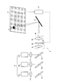
可変焦点ミラーとしては、例えば静電引力型を採用すればよい。図4(A)で例示するように、薄膜状の反射面である薄膜ミラー(メンブレン)35の背面に、小型の電極32を複数配置しておき、電気的吸引力にて薄膜ミラー35の面を吸引し、薄膜ミラー35の形状を符号36で例示するように変化させる。電極32に印加する電圧を制御することで薄膜ミラー35の曲面形状を変化させて反射光のビーム径を可変にする。可変焦点ミラーは小型化が可能で応答速度も速いため、操作性が改善される。なお、図4(A)において、電極32は基板31上に配置され、また薄膜ミラー35は基板31上にスペーサ33を介してアンカー34で狭持されている。また、電極32の配置は、図4(B)に示すように複数の電極32aを有するハニカム型であっても、また図4(C)に示すように複数の電極32bを有する同軸型であってもよい。
As the variable focus mirror, for example, an electrostatic attractive type may be adopted. As illustrated in FIG. 4A, a plurality of small electrodes 32 are arranged on the back surface of a thin film mirror (membrane) 35 that is a thin film-like reflecting surface, and the surface of the thin film mirror 35 is electrically attracted. And the shape of the thin film mirror 35 is changed as illustrated by the reference numeral 36. By controlling the voltage applied to the electrode 32, the curved surface shape of the thin film mirror 35 is changed to make the beam diameter of the reflected light variable. Since the variable focus mirror can be miniaturized and has a high response speed, the operability is improved. In FIG. 4A, the electrode 32 is disposed on the substrate 31, and the thin film mirror 35 is held by the anchor 34 via the spacer 33 on the substrate 31. Further, the arrangement of the electrodes 32 may be a honeycomb type having a plurality of electrodes 32a as shown in FIG. 4B or a coaxial type having a plurality of electrodes 32b as shown in FIG. 4C. May be.
可変焦点装置30でビーム径が変化されて出射した光線は、MEMSミラー14へ入射する。さらに光線は2軸のMEMSミラー14によりスクリーン15へ投射され、スクリーン15上に走査方式で画像を形成する。スクリーン15に投射された光線のスポットサイズは制御手段からの制御により可変焦点装置30で投影サイズに応じて変化され、画質の劣化が抑制される。このとき、第1の実施形態と同様に、可変焦点装置30は赤外線による距離検出装置16によって得られた投影サイズに応じた制御信号によって駆動される。
The light beam emitted with the beam diameter changed by the variable focus device 30 enters the MEMS mirror 14. Further, the light beam is projected onto the screen 15 by the biaxial MEMS mirror 14, and an image is formed on the screen 15 by a scanning method. The spot size of the light beam projected on the screen 15 is changed according to the projection size by the variable focus device 30 under the control of the control means, and the deterioration of the image quality is suppressed. At this time, similarly to the first embodiment, the variable focus device 30 is driven by a control signal corresponding to the projection size obtained by the distance detection device 16 using infrared rays.
また、可変焦点ミラーは、通常は曲率を変化させて集光点の位置を変えるように制御されるが、薄膜ミラー35の裏側に配設された複数の小型電極32のそれぞれを制御することで、自由な曲面形状へと変化させることもできる。従って、可変焦点装置30は電極32への印加電圧パターンにより、薄膜ミラー35の反射面を複雑な形状へと変化させて、入射してきたビーム(断面形状は丸)のスポット形状を丸ではなく例えば四角に近い形状などへと変形させることも可能となる。このように、可変焦点装置30は、スクリーン15上の光線のスポット形状を円形から略四角形へ変化させる制御を行うなど、スクリーン15上のスポットの形状も変えるように制御することが可能である。
The variable focus mirror is normally controlled so as to change the position of the condensing point by changing the curvature, but by controlling each of the plurality of small electrodes 32 disposed on the back side of the thin film mirror 35. It can also be changed to a free curved surface shape. Therefore, the variable focus device 30 changes the reflecting surface of the thin film mirror 35 into a complicated shape according to the voltage pattern applied to the electrode 32, and changes the spot shape of the incident beam (cross-sectional shape is a circle) instead of a circle. It can also be deformed into a shape close to a square. As described above, the variable focus device 30 can control the spot shape on the screen 15 to be changed, for example, by changing the spot shape of the light beam on the screen 15 from a circular shape to a substantially square shape.
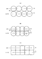
図5(A)で示すように形状が円形のスポットScの場合、スポットSc同士の間の隙間SSが形成されてしまう。円形のスポットScのまま隙間を埋めようとすると、図5(B)で示すようにスポットSc同士の重なり部分Dが生じて、重なっていない部分との差が生じ、画質が劣化する。これに対し、図5(C)に示すようにスポット形状を四角形に変化させる(四角形スポットSrにする)ことで、このような画素間の隙間を減少させることができ且つ重なり部分を減少させることができ、より画質の向上が図れる。
As shown in FIG. 5A, in the case of a circular spot Sc, a gap SS between the spots Sc is formed. If an attempt is made to fill the gap with the circular spot Sc, an overlapping portion D of the spots Sc is generated as shown in FIG. 5B, a difference from the non-overlapping portion is generated, and the image quality is deteriorated. On the other hand, as shown in FIG. 5C, the gap between the pixels can be reduced and the overlapping portion can be reduced by changing the spot shape to a square (a square spot Sr). Image quality can be improved.
以上説明したように、本実施形態では、第1又は第2の実施形態の効果の他に、可変焦点装置に可変焦点ミラーを使用することでスクリーン上のスポット形状を変化させることが可能である。そのため、画素間の重なり程度を均一化することができ、さらなる画質の改善が可能となる。また、駆動電圧が比較的低いため、消費電力を抑え、コストの抑制ができる。また、反射面の反射率を上げることで効率よくスポットサイズ制御が行え、明るい画像を得ることができる。
As described above, in this embodiment, in addition to the effects of the first or second embodiment, it is possible to change the spot shape on the screen by using the variable focus mirror in the variable focus device. . Therefore, the degree of overlap between pixels can be made uniform, and the image quality can be further improved. In addition, since the drive voltage is relatively low, power consumption can be reduced and costs can be reduced. Further, by increasing the reflectance of the reflecting surface, the spot size can be controlled efficiently and a bright image can be obtained.
また、可変焦点装置30は例に挙げた静電引力型のものでなくても構わない。例えばピエゾアクチュエータ型の可変焦点ミラーでもよい。ピエゾアクチュエータ型の可変焦点ミラーは薄膜状のミラー背面にピエゾアクチュエータを設置し、ピエゾの伸縮によってミラーの形状を変化させる。そのため、光線のスポットサイズをピエゾへの印加電圧によって制御することができる。ピエゾアクチュエータ型可変焦点ミラーは安価であり、コストを抑制することが可能である。また、反射型の可変焦点装置のため、透過型のような物質の光の吸収(透過率)の影響は受けないため、反射面の反射率を改善することで効率の良いスポットサイズ制御が行える。さらには制御電圧が比較的低くても駆動するため、消費電力を抑制することが可能である。
Further, the variable focus device 30 may not be the electrostatic attraction type mentioned above. For example, a piezo actuator type variable focus mirror may be used. A piezo actuator type variable focus mirror has a piezo actuator installed on the back of a thin film mirror and changes the shape of the mirror by expansion and contraction of the piezo. Therefore, the spot size of the light beam can be controlled by the voltage applied to the piezo. Piezo-actuator variable focus mirrors are inexpensive and can reduce costs. In addition, since it is a reflection type variable focus device, it is not affected by the light absorption (transmittance) of a material such as a transmission type. Therefore, efficient spot size control can be performed by improving the reflectivity of the reflection surface. . Furthermore, since the drive is performed even when the control voltage is relatively low, power consumption can be suppressed.
<第4の実施形態>
図6は、本発明の第4の実施形態に係る画像表示装置の内部構成を示す平面的模式図で、図中、6は画像表示装置である。図6において、第1の実施形態における画像表示装置1と同一の部分は同一の符号を付して、その応用例も含めて説明を一部省略し、簡単に説明する。なお、投影サイズによる画質の劣化低減に関しても第1の実施形態の説明と同様である。 <Fourth Embodiment>
FIG. 6 is a schematic plan view showing the internal configuration of an image display apparatus according to the fourth embodiment of the present invention. In the figure, 6 is an image display apparatus. In FIG. 6, the same parts as those of theimage display device 1 in the first embodiment are denoted by the same reference numerals, and a part of the description including application examples thereof will be omitted and briefly described. Note that the reduction in image quality degradation due to the projection size is the same as that described in the first embodiment.
図6は、本発明の第4の実施形態に係る画像表示装置の内部構成を示す平面的模式図で、図中、6は画像表示装置である。図6において、第1の実施形態における画像表示装置1と同一の部分は同一の符号を付して、その応用例も含めて説明を一部省略し、簡単に説明する。なお、投影サイズによる画質の劣化低減に関しても第1の実施形態の説明と同様である。 <Fourth Embodiment>
FIG. 6 is a schematic plan view showing the internal configuration of an image display apparatus according to the fourth embodiment of the present invention. In the figure, 6 is an image display apparatus. In FIG. 6, the same parts as those of the
図6で例示する画像表示装置6は、R、G、Bのレーザ光源10a~10cによって構成されるレーザ光源装置10、出力された光線を平行光とするコリメートレンズ11a~11c、それぞれの光線の波長のみを反射するダイクロイックミラー12a~12c、複数枚のレンズ61~63とレンズ可動機構とを備えた可変焦点装置60、走査方式で画像を形成するMEMSミラー14、画像を映し出すスクリーン15、及びスクリーン15との距離を検出する距離検出装置16によって構成されている。
An image display device 6 illustrated in FIG. 6 includes a laser light source device 10 composed of R, G, and B laser light sources 10a to 10c, collimating lenses 11a to 11c that convert the output light rays into parallel light, Dichroic mirrors 12a to 12c that reflect only a wavelength, a variable focus device 60 that includes a plurality of lenses 61 to 63 and a lens moving mechanism, a MEMS mirror 14 that forms an image by a scanning method, a screen 15 that displays an image, and a screen 15 is configured by a distance detection device 16 that detects a distance from the distance 15.
画像表示装置6は、R、G、Bそれぞれレーザ光源から出射された光線をコリメートレンズ11a~11cによって並行光とする。平行光としたレーザ光線をダイクロイックミラー12a~12cにより1束の光線へと合成する。合成したレーザ光は光線の光路上に配置された可変焦点装置60に入射する。
The image display device 6 converts the light beams emitted from the laser light sources R, G, and B into parallel light by the collimating lenses 11a to 11c. The parallel laser beams are combined into a bundle of beams by the dichroic mirrors 12a to 12c. The combined laser light is incident on the variable focus device 60 disposed on the optical path of the light beam.
入射した光線は可変焦点装置60によって光線のビーム径が変化される。本実施形態における可変焦点装置60は、数枚のレンズ(図6の例ではレンズ61~63)の組合せによって構成され、一部のレンズ(図6の例ではレンズ63)はアクチュエータ等のレンズ可動機構によって光軸方向へと移動させることが可能となっている。レンズを移動させることでレーザ光源から発せられた光線の集光点が制御され、出射される光線のビーム径を変化させることができる。
The beam diameter of the incident light beam is changed by the variable focus device 60. The variable focus device 60 in the present embodiment is configured by a combination of several lenses (lenses 61 to 63 in the example of FIG. 6), and some lenses (lenses 63 in the example of FIG. 6) are movable lenses such as actuators. The mechanism can be moved in the optical axis direction. By moving the lens, the condensing point of the light beam emitted from the laser light source is controlled, and the beam diameter of the emitted light beam can be changed.
可変焦点装置60でビーム径が変化されて出射した光線は、MEMSミラー14へ入射する。さらに光線は2軸のMEMSミラー14によってスクリーン15に投影され、スクリーン15上に走査方式で画像を形成する。スクリーン15に投射された光線のスポットサイズは制御手段からの制御により可変焦点装置60で投影サイズに応じて変化され、画質の劣化が抑制される。このとき、第1の実施形態と同様に、可変焦点装置60は赤外線による距離検出装置16によって得られた投影サイズに応じた制御信号によって駆動される。
The light beam emitted with the beam diameter changed by the variable focus device 60 is incident on the MEMS mirror 14. Further, the light beam is projected onto the screen 15 by the biaxial MEMS mirror 14, and an image is formed on the screen 15 by a scanning method. The spot size of the light beam projected on the screen 15 is changed according to the projection size by the variable focus device 60 under the control of the control means, and the deterioration of the image quality is suppressed. At this time, similarly to the first embodiment, the variable focus device 60 is driven by a control signal corresponding to the projection size obtained by the distance detection device 16 using infrared rays.
以上説明したように、本実施形態でも、ビーム径を自由に制御可能な光線がスクリーン15上へ投影されて画像を形成している。従って、本実施形態においても、第1~第3の実施形態の効果と同様に、スクリーン15に投射された光線は可変焦点装置60により光線の集光距離が制御されているため、投影サイズに応じてスポットサイズを変化させて画質を最適な状態にすることができる。さらに、本実施形態では、スポットサイズの変化を単純な機構の部品で容易に構成できると共に、ビーム径を拡大することなく画像を形成させることが可能となるため、部品の小型化とコスト削減が可能である。
As described above, also in this embodiment, the light beam whose beam diameter can be freely controlled is projected onto the screen 15 to form an image. Accordingly, in the present embodiment as well, as in the effects of the first to third embodiments, the light beam projected onto the screen 15 is controlled in the projection size because the light collection distance is controlled by the variable focus device 60. Accordingly, the spot size can be changed to optimize the image quality. Furthermore, in this embodiment, the spot size can be easily changed with simple mechanism parts, and an image can be formed without enlarging the beam diameter. Is possible.
<第5の実施形態>
図7は、本発明の第5の実施形態に係る画像表示装置の制御例を示す図で、図中、1、2、3、6はそれぞれ第1、第2、第3、第4の実施形態に係る画像表示装置である。 <Fifth Embodiment>
FIG. 7 is a diagram showing a control example of the image display apparatus according to the fifth embodiment of the present invention, in which 1, 2, 3 and 6 are the first, second, third and fourth implementations, respectively. 1 is an image display device according to an embodiment.
第1、第2、第3、第4の実施形態に係る画像表示装置1、2、3、6(以下、可変焦点装置13を備えた画像表示装置1で例示する)では、スクリーン15の傾きを特に考慮せずに説明した。従って、図7(A)で示すように、MEMSミラー14の面とほぼ平行に設置されたスクリーン15aでは画像72のように長方形に投影されるが、傾いたスクリーン15bでは画像71のように台形に投影されてしまう。
In the image display devices 1, 2, 3, 6 (hereinafter, exemplified by the image display device 1 including the variable focus device 13) according to the first, second, third, and fourth embodiments, the inclination of the screen 15 Was explained without special consideration. Therefore, as shown in FIG. 7A, the screen 15a installed substantially parallel to the surface of the MEMS mirror 14 is projected in a rectangular shape like an image 72, but the tilted screen 15b is trapezoidal like an image 71. Will be projected.
このような形状の不具合は、スクリーン15の傾きを検出し、それに応じてレーザ光線を制御することにより、形状を補正することで改善できる。すなわち、図7(B)で示すように、MEMSミラー14の面から傾いたスクリーン15bでも画像73のように長方形に投影させるよう制御することができる。なお、この制御を行うと、平行に設置されたスクリーン15aでは画像74のように台形に投影されることになる。
Such defects in the shape can be improved by correcting the shape by detecting the tilt of the screen 15 and controlling the laser beam accordingly. That is, as shown in FIG. 7B, the screen 15b tilted from the surface of the MEMS mirror 14 can be controlled to be projected into a rectangle like an image 73. When this control is performed, the screen 15a installed in parallel is projected into a trapezoid like an image 74.
傾きの検出は、制御手段に傾き検出手段を備えておくことで実現できる。この傾き検出手段は、上述した距離検出装置16を援用し、スクリーン15の複数位置(3以上の位置が好ましい)での距離を計測することで、幾何的な演算により傾きが算出できる。例えば、距離検出装置16によって投射される範囲の位置関係を測定し、そこから求めることができる。例えば、少なくともスクリーン15の走査開始ライン中の一点及び走査終了ラインの1点などの2点で投影距離を検出し、上下方向の傾きを求めることができる。同様に、水平方向に異なる2点で投影距離を検出し、左右方向の傾きを求めることができる。
Detecting tilt can be realized by providing tilt detecting means in the control means. This inclination detecting means can calculate the inclination by geometric calculation by measuring the distance at a plurality of positions (preferably three or more positions) of the screen 15 with the aid of the distance detection device 16 described above. For example, the positional relationship of the range projected by the distance detection device 16 can be measured and obtained therefrom. For example, the projection distance can be detected at least at two points such as one point on the scanning start line of the screen 15 and one point on the scanning end line, and the vertical inclination can be obtained. Similarly, the projection distance can be detected at two different points in the horizontal direction, and the left / right inclination can be obtained.
上述の形状補正を行うためのレーザ光線の制御について説明する。例えば、スクリーン15bのように上面が手前に傾いていると画像71のように上面が小さく下側が大きな台形になる。これを補正するために、画像74のように下側を投影するにつれて徐々に光線の出射角度を小さくしていく必要がある。その方法としては(I)レーザ光源の制御と(II)MEMSミラー14の制御の2通りの方法が挙げられる。
The control of the laser beam for performing the above-described shape correction will be described. For example, if the upper surface is inclined toward the front like the screen 15b, the upper surface is small and the lower side is a large trapezoid like the image 71. In order to correct this, it is necessary to gradually decrease the light emission angle as the lower side is projected as in the image 74. As the method, there are two methods of (I) control of the laser light source and (II) control of the MEMS mirror 14.
(I)レーザ光源の制御による方法は、MEMSミラー14の振り角は一定としたまま、レーザ光源装置10においてレーザの点灯させるタイミングを変化させる方法がある。つまり、画像の下側を走査するにつれて徐々に点灯させる水平方向の範囲を減少させるように、すなわち徐々に出射角度の小さい部分だけ点灯させるように駆動させる。この方法は、次に説明する(II)の方法に比べて、MEMSミラー14のような可動デバイスを動的に制御することがないため、寿命等を改善できる。
(I) As a method of controlling the laser light source, there is a method of changing the timing of turning on the laser in the laser light source device 10 while keeping the swing angle of the MEMS mirror 14 constant. That is, it is driven so as to gradually reduce the horizontal range to be lit as the lower side of the image is scanned, that is, to gradually illuminate only a portion having a small emission angle. Compared with the method (II) described below, this method does not dynamically control a movable device such as the MEMS mirror 14 and can therefore improve the life and the like.
徐々に点灯させる水平方向の範囲を減少させた時、光線が平行光ではなく設計上一定の拡がり角をもった場合には、画像表示装置1から距離の遠い画面下側部分のスポットサイズが大きくなってしまうため画面にムラができ、画質が低下する(画面の下側にいくほどぼやけた画像となる)。しかし、このような画質の低下は、制御手段が可変焦点装置13にスポットサイズを動的に変化させるよう制御することで、例えば画像73の場合には下側を投影するにつれて徐々にスポットサイズを小さめにするよう制御することで、改善できる。
When the horizontal range to be lit gradually is reduced, if the light beam is not parallel light but has a certain divergence angle by design, the spot size of the lower part of the screen far from the image display device 1 is large. As a result, the screen becomes uneven, and the image quality deteriorates (the lower the screen is, the more blurred the image is). However, such a decrease in image quality is caused by the control means controlling the variable focus device 13 to dynamically change the spot size. For example, in the case of the image 73, the spot size is gradually increased as the lower side is projected. It can be improved by controlling it to be smaller.
このときの制御手段は、同じく得たスクリーン15の傾き(傾きの角度)に応じて、スクリーン15上の画面内のスポットサイズを変更するように、可変焦点装置13を制御すればよい。ここで、制御手段は、スクリーン15が正対(平行に投影)しておらず傾いていた場合には、画像を表示中、常に動的にスポットサイズを変化させ続けることになる。なお、これに対し、正対している場合は、基本的に投影サイズに最適なスポットサイズとなるよう制御して、それ以降、一定のスポットサイズで画像を表示すればよい。
The control means at this time may control the variable focus device 13 so as to change the spot size in the screen on the screen 15 according to the obtained inclination (angle of inclination) of the screen 15. Here, when the screen 15 is not directly facing (projected in parallel) and tilted, the control means always keeps changing the spot size dynamically while displaying an image. On the other hand, when facing directly, the spot size is basically controlled to be the optimum spot size, and thereafter, an image is displayed with a constant spot size.
若しくは、制御手段は、直接、距離検出装置16から得たその走査点での距離に応じてスポットサイズを変更するように、可変焦点装置13を制御してもよい。このような制御も、間接的にスクリーン15の傾きに応じてスポットサイズを変更する制御に該当する。より簡単な構成では、スクリーン15の走査開始点及び走査終了点の2点で投影距離を検出し、この2点を補間するような投影距離に基づきスポットサイズを決定して制御するとよい。
Alternatively, the control means may directly control the variable focus device 13 so as to change the spot size according to the distance at the scanning point obtained from the distance detection device 16. Such control also corresponds to control for changing the spot size indirectly according to the inclination of the screen 15. In a simpler configuration, the projection distance may be detected at two points of the scanning start point and the scanning end point of the screen 15, and the spot size may be determined and controlled based on the projection distance that interpolates these two points.
(II)MEMSミラー14の制御による方法は、MEMSミラー14の振り角自体を動的に変化させる方法である。つまり、画面の下側を表示するにつれてMEMSミラー14の振り角を小さくするように制御する。光線が平行光ではなく設計上一定の拡がり角をもった場合には、スクリーン15bが傾いていることから画面の部分毎でスポットサイズが異なり画質が低下するが、これも同様に可変焦点装置13を傾きに応じて動的に制御して補正することで改善できる。
(II) The method of controlling the MEMS mirror 14 is a method of dynamically changing the swing angle of the MEMS mirror 14 itself. That is, control is performed so that the swing angle of the MEMS mirror 14 is reduced as the lower side of the screen is displayed. When the light beam is not parallel light but has a certain divergence angle by design, the screen 15b is tilted, so that the spot size is different for each portion of the screen and the image quality is deteriorated. Can be improved by dynamically controlling and correcting according to the inclination.
このように、スクリーン15が傾いている場合でも傾いていない場合でも、レーザ光線の制御によりその投影形状を補正すると共に、制御手段及び可変焦点装置13によりビーム径の大きさをスクリーン15の投影位置毎に可変制御することで、スクリーン15の傾きに応じたスポットサイズに制御することが可能となり、最適な画質の画像を得ることができる。なお、光線が平行光でないことを前提に上記(I),(II)について説明したが、出射光が平行光である場合には投影サイズによって画質のバラつきが出てしまうため、平行光である場合であってもスポットサイズの調整を行うとよい。
In this way, whether the screen 15 is tilted or not, the projection shape is corrected by controlling the laser beam, and the size of the beam diameter is adjusted by the control means and the variable focus device 13 to the projection position of the screen 15. By variably controlling each time, it becomes possible to control the spot size according to the inclination of the screen 15, and an image with an optimum image quality can be obtained. The above (I) and (II) have been described on the premise that the light beam is not parallel light. However, when the emitted light is parallel light, the image quality varies depending on the projection size, and thus the parallel light is used. Even in this case, the spot size may be adjusted.
<第6の実施形態>
第1~第5の実施形態に係る画像表示装置では、制御手段は投影サイズに応じてスポットサイズの変更を行うよう可変焦点装置を制御したが、第6の実施形態に係る画像表示装置は、投影サイズ(投影距離)の代わりに、或いは投影サイズによる制御の後の微調整として、ユーザ操作に応じて可変焦点装置を制御する。 <Sixth Embodiment>
In the image display devices according to the first to fifth embodiments, the control unit controls the variable focus device so as to change the spot size according to the projection size. However, the image display device according to the sixth embodiment Instead of the projection size (projection distance) or as a fine adjustment after the control by the projection size, the variable focus device is controlled according to the user operation.
つまり、本実施形態に係る画像表示装置の制御手段は、スポットサイズを変更するユーザ操作を受け付ける操作手段を有し、その操作手段で受け付けたユーザ操作に応じたスポットサイズの変更を行うように、可変焦点装置を制御する。このような操作手段、すなわちユーザインタフェースは、調整用レバーや調整用つまみを設けるなど、画像表示装置に全て含めるように搭載してもよいし、一部を画像表示装置に接続するテレビやPC等の映像ソース側でユーザ操作を行わせ、その操作信号を受信してもよい。
That is, the control unit of the image display apparatus according to the present embodiment has an operation unit that receives a user operation for changing the spot size, and changes the spot size according to the user operation received by the operation unit. Control the variable focus device. Such an operation means, that is, a user interface may be mounted so as to be included in the image display device by providing an adjustment lever, an adjustment knob, or a television or a PC partially connected to the image display device. A user operation may be performed on the video source side and the operation signal may be received.
このように、可変焦点装置をユーザが自由に調整可能にすることで、ユーザの好みに応じた画質となるよう自由に設定が可能である。これにより、この画像表示装置を汎用性の高いものにすることができる。
In this way, by allowing the user to freely adjust the variable focus device, it is possible to freely set the image quality according to the user's preference. Thereby, this image display apparatus can be made highly versatile.
実際、スポットサイズによって画素間の重なりの度合いが変わるため、ユーザである視聴者が感じる画質の解像感が変わる。つまり、重なりが少ないとシャープな画質になり、重なりが多くなるにつれてシャープさが無くなる。しかし、本実施形態では、上述のごとき制御手段により、ユーザがスポットサイズを自由に調整することを可能にしているため、この重なり具合がユーザ調整できる。従って、本実施形態では、画像の解像感をユーザ好みに調整し、結果としてユーザ好みの画質に調整することができる。
Actually, since the degree of overlap between pixels varies depending on the spot size, the resolution of the image quality felt by the viewer who is the user varies. That is, sharp image quality is obtained when there is little overlap, and sharpness disappears as the overlap increases. However, in the present embodiment, since the user can freely adjust the spot size by the control means as described above, the overlapping degree can be adjusted by the user. Therefore, in this embodiment, the resolution of the image can be adjusted to the user's preference, and as a result, the image quality can be adjusted to the user's preference.
以上、本発明の各実施形態について、RGBを合成後に走査することを前提に説明したが、例えばRGBそれぞれに対して可変焦点装置及びMEMSミラーを設けて、走査後(例えばスクリーン上で)合成させる構成を採用してもよい。その場合、画素毎の色はRGB光線の重なりによって表現されるため、画質を保つためにはRGB間のピッチ及びビーム径は同じである必要がある。
As described above, each embodiment of the present invention has been described on the premise that scanning is performed after combining RGB. However, for example, a variable focus device and a MEMS mirror are provided for each of RGB and combined after scanning (for example, on a screen). A configuration may be employed. In that case, since the color for each pixel is expressed by the overlap of RGB rays, the pitch and beam diameter between RGB need to be the same in order to maintain the image quality.
As described above, each embodiment of the present invention has been described on the premise that scanning is performed after combining RGB. However, for example, a variable focus device and a MEMS mirror are provided for each of RGB and combined after scanning (for example, on a screen). A configuration may be employed. In that case, since the color for each pixel is expressed by the overlap of RGB rays, the pitch and beam diameter between RGB need to be the same in order to maintain the image quality.
Claims (11)
- 光線を発する光源装置と、スクリーン上に画像を形成する走査型の画像形成手段と、前記光源装置から発せられた光線が該画像形成手段に到達するまでの光路中に配設された可変焦点装置と、前記スクリーンへ投射される光線のスポットサイズを変更するように、前記可変焦点装置を制御する制御手段とを備えたことを特徴とする画像表示装置。 Light source device for emitting light, scanning-type image forming means for forming an image on a screen, and variable focus device disposed in an optical path until the light emitted from the light source device reaches the image forming means And an image display device comprising: control means for controlling the variable focus device so as to change a spot size of the light beam projected onto the screen.
- 前記制御手段は、投影サイズを検出する投影サイズ検出手段を有し、該投影サイズ検出手段で検出された投影サイズに応じて、前記スポットサイズを変更するように、前記可変焦点装置を制御することを特徴とする請求項1に記載の画像表示装置。 The control means has a projection size detection means for detecting a projection size, and controls the variable focus device so as to change the spot size according to the projection size detected by the projection size detection means. The image display apparatus according to claim 1.
- 前記投影サイズ検出手段は、前記スクリーンまでの投影距離を検出する距離検出手段であり、前記制御手段は、前記距離検出手段で検出された投影距離に対応した投影サイズに応じて、前記スポットサイズを変更するように、前記可変焦点装置を制御することを特徴とする請求項2に記載の画像表示装置。 The projection size detection means is a distance detection means for detecting a projection distance to the screen, and the control means determines the spot size according to the projection size corresponding to the projection distance detected by the distance detection means. The image display apparatus according to claim 2, wherein the variable focus apparatus is controlled so as to be changed.
- 前記制御手段は、前記スポットサイズを変更するユーザ操作を受け付ける操作手段を有し、該操作手段で受け付けたユーザ操作に応じた前記スポットサイズの変更を行うように、前記可変焦点装置を制御することを特徴とする請求項1に記載の画像表示装置。 The control unit includes an operation unit that receives a user operation for changing the spot size, and controls the variable focus device so as to change the spot size according to the user operation received by the operation unit. The image display apparatus according to claim 1.
- 前記可変焦点装置は、前記スポットサイズを電気的に制御することが可能な素子を有することを特徴とする請求項1~4のいずれか1項に記載の画像表示装置。 5. The image display device according to claim 1, wherein the variable focus device has an element capable of electrically controlling the spot size.
- 前記可変焦点装置は、前記素子として液晶レンズを有し、該液晶レンズへの印加電圧制御によって前記スポットサイズを変更することを特徴とする請求項5に記載の画像表示装置。 6. The image display device according to claim 5, wherein the variable focus device has a liquid crystal lens as the element, and changes the spot size by controlling a voltage applied to the liquid crystal lens.
- 前記可変焦点装置は、前記素子として液体レンズを有し、該液体レンズの印加電圧制御によって前記スポットサイズを変更することを特徴とする請求項5に記載の画像表示装置。 6. The image display device according to claim 5, wherein the variable focus device has a liquid lens as the element, and changes the spot size by controlling an applied voltage of the liquid lens.
- 前記可変焦点装置は、前記素子として、ミラーの曲面形状が可変である可変焦点ミラーを有し、該可変焦点ミラーへの印加電圧制御によって前記スポットサイズを変更することを特徴とする請求項5に記載の画像表示装置。 6. The variable focus apparatus according to claim 5, wherein the variable focus device includes a variable focus mirror having a variable mirror curved surface as the element, and the spot size is changed by controlling an applied voltage to the variable focus mirror. The image display device described.
- 前記可変焦点装置は、前記スクリーン上でのスポットの形状を略四角形となるよう制御することを特徴とする請求項8に記載の画像表示装置。 9. The image display device according to claim 8, wherein the variable focus device controls the shape of the spot on the screen to be a substantially square shape.
- 前記可変焦点装置は、複数枚のレンズと、該レンズの少なくとも1つを光軸方向に移動させるレンズ可動機構とを有し、該レンズ可動機構でレンズを移動させることによって前記スポットサイズを変更することを特徴とする請求項1~4のいずれか1項に記載の画像表示装置。 The variable focus device includes a plurality of lenses and a lens moving mechanism that moves at least one of the lenses in the optical axis direction, and changes the spot size by moving the lens by the lens moving mechanism. The image display device according to any one of claims 1 to 4, wherein:
- 前記制御手段は、前記スクリーンの傾きを検出する傾き検出手段を有し、該傾き検出手段で検出された傾きに応じて、前記スクリーン上の画面内でスポットサイズを変更するように、前記可変焦点装置を制御することを特徴とする請求項1~10のいずれか1項に記載の画像表示装置。 The control means has an inclination detection means for detecting the inclination of the screen, and the variable focus is set so as to change a spot size in the screen on the screen according to the inclination detected by the inclination detection means. The image display device according to any one of claims 1 to 10, wherein the device is controlled.
Priority Applications (1)
| Application Number | Priority Date | Filing Date | Title |
|---|---|---|---|
| US12/918,021 US20100315605A1 (en) | 2008-02-18 | 2009-02-16 | Image display apparatus |
Applications Claiming Priority (2)
| Application Number | Priority Date | Filing Date | Title |
|---|---|---|---|
| JP2008036182A JP2009193008A (en) | 2008-02-18 | 2008-02-18 | Image display device |
| JP2008-036182 | 2008-02-18 |
Publications (1)
| Publication Number | Publication Date |
|---|---|
| WO2009104524A1 true WO2009104524A1 (en) | 2009-08-27 |
Family
ID=40985405
Family Applications (1)
| Application Number | Title | Priority Date | Filing Date |
|---|---|---|---|
| PCT/JP2009/052460 WO2009104524A1 (en) | 2008-02-18 | 2009-02-16 | Image display device |
Country Status (3)
| Country | Link |
|---|---|
| US (1) | US20100315605A1 (en) |
| JP (1) | JP2009193008A (en) |
| WO (1) | WO2009104524A1 (en) |
Cited By (2)
| Publication number | Priority date | Publication date | Assignee | Title |
|---|---|---|---|---|
| JP2014085605A (en) * | 2012-10-26 | 2014-05-12 | Hitachi Media Electoronics Co Ltd | Laser beam display device and mirror control method therefor |
| CN104111528A (en) * | 2014-06-23 | 2014-10-22 | 武汉市安曼特微显示科技有限公司 | Free switching control system of single-lamp projector lighting device |
Families Citing this family (45)
| Publication number | Priority date | Publication date | Assignee | Title |
|---|---|---|---|---|
| US8251517B2 (en) * | 2007-12-05 | 2012-08-28 | Microvision, Inc. | Scanned proximity detection method and apparatus for a scanned image projection system |
| IL192583A (en) * | 2008-07-02 | 2014-01-30 | Btendo Ltd | Mems device comprising oscillations measurement means |
| US20120113397A1 (en) * | 2009-04-21 | 2012-05-10 | Yusuke Hirao | Scanning Optical System and Projector Provided with the Same |
| WO2011012168A1 (en) * | 2009-07-31 | 2011-02-03 | Lemoptix Sa | Optical micro-projection system and projection method |
| WO2011046035A1 (en) * | 2009-10-15 | 2011-04-21 | 日本電気株式会社 | Image projection device, image protection method, distance measuring device and distance measuring method |
| TWI396893B (en) * | 2009-10-22 | 2013-05-21 | Univ Nat Chiao Tung | Electro-optical device |
| JP5488803B2 (en) * | 2010-01-07 | 2014-05-14 | 株式会社リコー | OPTICAL DEVICE, PROJECTION IMAGE DISPLAY DEVICE HAVING THE OPTICAL DEVICE, AND OPTICAL DEVICE MANUFACTURING METHOD |
| JP5701573B2 (en) * | 2010-06-15 | 2015-04-15 | オリンパス株式会社 | Scanner, scanning illumination device, and scanning observation device |
| JP5803184B2 (en) * | 2010-11-19 | 2015-11-04 | 株式会社リコー | Image projection apparatus and memory access method |
| US9188846B2 (en) | 2011-02-18 | 2015-11-17 | Nec Corporation | Scanning-type image display device and its image display method |
| US20140028984A1 (en) * | 2011-04-05 | 2014-01-30 | Akihiro Osaka | Light source apparatus and projection display apparatus |
| JP5758717B2 (en) * | 2011-06-22 | 2015-08-05 | スタンレー電気株式会社 | Vehicle lighting device |
| WO2013046904A1 (en) * | 2011-09-27 | 2013-04-04 | 日本電気株式会社 | Optical scanning device, image display device and method for adjusting projection area |
| JP2013125166A (en) | 2011-12-15 | 2013-06-24 | Seiko Epson Corp | Lighting system |
| JP5832919B2 (en) | 2012-02-08 | 2015-12-16 | 日立マクセル株式会社 | Laser projector |
| DE102012202026A1 (en) * | 2012-02-10 | 2013-08-14 | Robert Bosch Gmbh | Projection apparatus and method for operating a projection apparatus |
| WO2013160982A1 (en) * | 2012-04-23 | 2013-10-31 | パイオニア株式会社 | Image generating apparatus |
| JP6069754B2 (en) * | 2012-06-01 | 2017-02-01 | インテル・コーポレーション | Device for projecting light, projection device, module for projection device, and projection device manufacturing method |
| US9348138B2 (en) * | 2012-06-15 | 2016-05-24 | Mitsubishi Electric Corporation | Laser processing device |
| JP2014029395A (en) * | 2012-07-31 | 2014-02-13 | Hitachi Media Electoronics Co Ltd | Luminous flux scanning device and luminous flux scanning type image projection device |
| JP6089551B2 (en) | 2012-10-09 | 2017-03-08 | セイコーエプソン株式会社 | Lighting device |
| CN103869584B (en) * | 2012-12-12 | 2016-06-15 | 光宝科技股份有限公司 | It is applied to the bare engine module of projection arrangement |
| WO2014104203A1 (en) * | 2012-12-26 | 2014-07-03 | シチズンホールディングス株式会社 | Projection device |
| CN104247574B (en) * | 2013-03-06 | 2016-01-06 | 优志旺电机株式会社 | Light supply apparatus and projector |
| JP6100080B2 (en) * | 2013-05-08 | 2017-03-22 | 株式会社東芝 | Projector and portable terminal |
| JP2015034919A (en) * | 2013-08-09 | 2015-02-19 | 株式会社デンソー | Information display device |
| JP6053171B2 (en) * | 2013-10-18 | 2016-12-27 | 増田 麻言 | Scanning projection apparatus and portable projection apparatus |
| KR102135356B1 (en) * | 2013-10-24 | 2020-07-17 | 엘지전자 주식회사 | Image projection apparatus |
| JP6281174B2 (en) * | 2014-03-25 | 2018-02-21 | スタンレー電気株式会社 | Vehicle lamp and coupling distributor |
| TWI588535B (en) * | 2014-11-20 | 2017-06-21 | 英特爾股份有限公司 | Adjustable focal plane optical system |
| TWI688789B (en) * | 2014-11-20 | 2020-03-21 | 美商英特爾股份有限公司 | Virtual image generator and method to project a virtual image |
| WO2016121534A1 (en) * | 2015-01-29 | 2016-08-04 | アルプス電気株式会社 | Display device |
| US10670857B2 (en) * | 2015-02-13 | 2020-06-02 | Nec Corporation | Projection device and interface device having mirror which reflects light other than zero-order light toward a projection lens |
| DE102015209418A1 (en) * | 2015-05-22 | 2016-11-24 | Robert Bosch Gmbh | Scanning device and scanning method |
| JP6516223B2 (en) * | 2015-06-30 | 2019-05-22 | パナソニックIpマネジメント株式会社 | Display device |
| KR20170079355A (en) | 2015-12-30 | 2017-07-10 | 엘지이노텍 주식회사 | Light emitting apparatus, optical module including the apparatus, and vehicle including the module |
| US10962764B2 (en) * | 2016-04-01 | 2021-03-30 | Intel Corporation | Laser projector and camera |
| DE102016205413A1 (en) * | 2016-04-01 | 2017-10-05 | Robert Bosch Gmbh | Projection device and method for projecting image information onto a projection surface |
| JP6680109B2 (en) * | 2016-06-28 | 2020-04-15 | 株式会社デンソー | Video projection device and head-up display device including the same |
| US10239178B2 (en) | 2016-10-17 | 2019-03-26 | Virtek Vision International, ULC | Laser projector with dynamically adaptable focus |
| GB2565834B (en) * | 2017-08-25 | 2020-05-20 | Dualitas Ltd | Display system |
| US11166851B2 (en) | 2019-01-18 | 2021-11-09 | Alcon Inc. | Controlling the position of the focal point of a laser beam |
| US11714282B2 (en) | 2019-03-29 | 2023-08-01 | Meta Platforms Technologies, Llc | Compact array light source for scanning display |
| US11366309B2 (en) * | 2019-03-29 | 2022-06-21 | Facebook Technologies, Llc | Scanning projector display with multiple light engines |
| CN112882230B (en) * | 2019-11-29 | 2023-05-26 | 宁波舜宇车载光学技术有限公司 | Optical system and method for eliminating color edge |
Citations (4)
| Publication number | Priority date | Publication date | Assignee | Title |
|---|---|---|---|---|
| JP2002055297A (en) * | 2000-08-11 | 2002-02-20 | Ngk Insulators Ltd | Laser beam output device |
| JP2002244063A (en) * | 2001-02-20 | 2002-08-28 | Ricoh Co Ltd | Laser beam scanner |
| JP2003255263A (en) * | 2001-12-25 | 2003-09-10 | Ricoh Co Ltd | Image display device and image display method |
| JP2005259128A (en) * | 2004-03-11 | 2005-09-22 | Symbol Technologies Inc | Optical modulation increasing operating range and performance of electro-optical reading apparatus |
Family Cites Families (4)
| Publication number | Priority date | Publication date | Assignee | Title |
|---|---|---|---|---|
| US7446822B2 (en) * | 2002-05-15 | 2008-11-04 | Symbol Technologies, Inc. | High-resolution image projection |
| JP4020043B2 (en) * | 2003-08-25 | 2007-12-12 | カシオ計算機株式会社 | Projection apparatus, projection method, and program |
| JPWO2006115210A1 (en) * | 2005-04-22 | 2008-12-18 | 松下電器産業株式会社 | Projection display device |
| JP4750626B2 (en) * | 2006-05-31 | 2011-08-17 | シチズンホールディングス株式会社 | Automatic focusing device |
-
2008
- 2008-02-18 JP JP2008036182A patent/JP2009193008A/en active Pending
-
2009
- 2009-02-16 US US12/918,021 patent/US20100315605A1/en not_active Abandoned
- 2009-02-16 WO PCT/JP2009/052460 patent/WO2009104524A1/en active Application Filing
Patent Citations (4)
| Publication number | Priority date | Publication date | Assignee | Title |
|---|---|---|---|---|
| JP2002055297A (en) * | 2000-08-11 | 2002-02-20 | Ngk Insulators Ltd | Laser beam output device |
| JP2002244063A (en) * | 2001-02-20 | 2002-08-28 | Ricoh Co Ltd | Laser beam scanner |
| JP2003255263A (en) * | 2001-12-25 | 2003-09-10 | Ricoh Co Ltd | Image display device and image display method |
| JP2005259128A (en) * | 2004-03-11 | 2005-09-22 | Symbol Technologies Inc | Optical modulation increasing operating range and performance of electro-optical reading apparatus |
Cited By (2)
| Publication number | Priority date | Publication date | Assignee | Title |
|---|---|---|---|---|
| JP2014085605A (en) * | 2012-10-26 | 2014-05-12 | Hitachi Media Electoronics Co Ltd | Laser beam display device and mirror control method therefor |
| CN104111528A (en) * | 2014-06-23 | 2014-10-22 | 武汉市安曼特微显示科技有限公司 | Free switching control system of single-lamp projector lighting device |
Also Published As
| Publication number | Publication date |
|---|---|
| US20100315605A1 (en) | 2010-12-16 |
| JP2009193008A (en) | 2009-08-27 |
Similar Documents
| Publication | Publication Date | Title |
|---|---|---|
| WO2009104524A1 (en) | Image display device | |
| US7972011B2 (en) | Image projection apparatus and image projection system having beam deflection section | |
| US7677736B2 (en) | Illumination light source and two-dimensional image display using same | |
| US7021765B2 (en) | Illumination optical system and projection display optical system | |
| RU2464603C1 (en) | Optical scanning unit, image projector having said unit, car display device on windscreen and mobile telephone | |
| US7401927B2 (en) | Method of illumination and display apparatus | |
| JP2008509448A (en) | 2D image projection system | |
| WO2012111698A1 (en) | Scanning image display device, and image display method for same | |
| US7614752B2 (en) | Image display apparatus and method, and driving apparatus and method | |
| WO2015044995A1 (en) | Display device | |
| US8264636B2 (en) | Laser backside irradiation device and liquid crystal display device | |
| JP4144713B2 (en) | Projection display | |
| US20070041077A1 (en) | Pocket-sized two-dimensional image projection system | |
| US9354503B2 (en) | Laser projector | |
| JP2009157111A (en) | Image display device | |
| JP2007121539A (en) | Image display device | |
| TW200909975A (en) | Device and method for compensating at least one non-linearity and laser projection system | |
| JP2011095291A (en) | Projector | |
| KR100201827B1 (en) | Projection system of optical path control system | |
| JP2007079087A (en) | Image display apparatus and its control method | |
| JP2014085605A (en) | Laser beam display device and mirror control method therefor | |
| JP2007121802A (en) | Picture display apparatus and method of displaying picture | |
| KR100208662B1 (en) | Projection image display system and a projection method using the same | |
| CN116449633A (en) | Projection optical machine with light modulation component and scanning galvanometer component and projector | |
| KR100208661B1 (en) | Optical projection system and an optical projection method using the same |
Legal Events
| Date | Code | Title | Description |
|---|---|---|---|
| 121 | Ep: the epo has been informed by wipo that ep was designated in this application |
Ref document number: 09712626 Country of ref document: EP Kind code of ref document: A1 |
|
| DPE1 | Request for preliminary examination filed after expiration of 19th month from priority date (pct application filed from 20040101) | ||
| WWE | Wipo information: entry into national phase |
Ref document number: 12918021 Country of ref document: US |
|
| NENP | Non-entry into the national phase |
Ref country code: DE |
|
| 122 | Ep: pct application non-entry in european phase |
Ref document number: 09712626 Country of ref document: EP Kind code of ref document: A1 |