WO2009104331A1 - 領域指定装置、線画処理装置、領域指定プログラム、および線画処理プログラム - Google Patents
領域指定装置、線画処理装置、領域指定プログラム、および線画処理プログラム Download PDFInfo
- Publication number
- WO2009104331A1 WO2009104331A1 PCT/JP2008/072765 JP2008072765W WO2009104331A1 WO 2009104331 A1 WO2009104331 A1 WO 2009104331A1 JP 2008072765 W JP2008072765 W JP 2008072765W WO 2009104331 A1 WO2009104331 A1 WO 2009104331A1
- Authority
- WO
- WIPO (PCT)
- Prior art keywords
- designation
- character
- closed
- area
- line drawing
- Prior art date
- Legal status (The legal status is an assumption and is not a legal conclusion. Google has not performed a legal analysis and makes no representation as to the accuracy of the status listed.)
- Ceased
Links
Images




Classifications
-
- G—PHYSICS
- G06—COMPUTING OR CALCULATING; COUNTING
- G06T—IMAGE DATA PROCESSING OR GENERATION, IN GENERAL
- G06T11/00—Two-dimensional [2D] image generation
- G06T11/40—Filling planar surfaces by adding surface attributes, e.g. adding colours or textures
Definitions
- An area designating apparatus and an area designating program for designating a closed area of the character and a line drawing processing apparatus for performing color processing on the closed area of the character for a character represented by a line drawing and composed of a plurality of closed areas And a line drawing processing program.
- “Manga” refers to a line drawing drawn in monochrome (monochrome) with a unique Japanese texture.
- gradation expression and emotion expression in monochrome manga are realized by monochrome (monochrome) drawing using various tones, hanging meshes, effect lines, solids, and the like. With such an expression technique, manga has different nuances from English comics.
- the monochrome printing technique is usually employed. This monochrome printing technique is advantageous (inexpensive) in terms of cost compared to the color printing technique.
- Patent Document 1 a technique for performing a coloring process on a line drawing has been conventionally known (for example, Patent Document 1).
- the color to be colored in each region of the uncolored line drawing is determined by comparing the center of gravity of both regions and the circumscribed rectangle size for the region of the colored image and the region of the uncolored line drawing. Is done.
- Patent Document 1 has a problem that the coloring process cannot be performed on an uncolored character unless it is compared with a colored image. As a result, it is not appropriate to apply the technique of Patent Document 1 to manga coloring that requires repeated coloring processing on characters.
- an object of the present invention is to provide an area designation device that can easily designate a closed area of a character represented by a line drawing when realizing colorization of a manga.
- the invention of claim 1 is an area designating device for designating a closed area of a character represented by a line drawing and composed of a plurality of closed areas, the display means And a plurality of closed region designating means for collectively designating the character characteristic portion and the closed region of the character by a plurality of closed region designating pointers arranged on the character displayed on the display means.
- the plurality of closed region designation pointers are arranged at predetermined positions with reference to the feature portion designation window for designating the feature portion of the character and the feature portion designation window, and a plurality of points for designating the closed region of the character. And a region designation point.
- the multiple closed area designation unit sets a feature part designation window that associates the feature part designation window with the feature part of the character.
- a region designation point setting unit for setting the plurality of region designation points.
- the region designated point setting means sets the plurality of region designated points
- the closed region designated by each region designated point is colored.
- the color to be set is set.
- the region designation figure is a figure set around a corresponding region designation point among the plurality of region designation points,
- the plurality of area designating means collectively designate closed areas overlapping with each area designating figure.
- the invention according to claim 5 is the area specifying device according to claim 1, wherein the plural closed area specifying means is capable of enlarging or reducing the plural closed area specifying pointer.
- the invention of claim 6 is the area specifying device according to claim 1, wherein the plural closed area specifying means is capable of rotating the plural closed area specifying pointer.
- the invention of claim 7 is a line drawing processing device, which is expressed by a line drawing using the region designating device of claim 1 and is colored for a character composed of a plurality of closed regions. Processing is performed.
- the invention according to claim 8 is a line drawing processing apparatus that performs coloring processing on a character that is expressed by a line drawing and is composed of a plurality of closed regions, the display means;
- a plurality of closed region designation pointers having a feature portion designation window for designating a feature portion and a plurality of region designation points which are arranged at predetermined positions with reference to the feature portion designation window and which designate the closed region of the character
- the characteristic part registration means for registering the characteristic part of the character designated by the characteristic part designation window, and the line drawing displayed on the display means
- Feature portion search means for searching for a character having the same shape as the feature portion registered by the feature portion registration means;
- the plurality of closed region designation pointers are moved so that the feature portion designation window is positioned at a portion corresponding to the feature portion registered by the feature portion registration means among the character portions searched by the feature portion search means.
- a plurality of pointer moving means for specifying the closed areas of the character searched by the characteristic part searching means based on each area specifying point of the plurality of closed area specifying pointers moved by the pointer moving means. It is characterized by comprising: a closed region designating unit; and a coloring unit for performing a coloring process on the closed region collectively designated by the plurality of closed region designating units.
- a plurality of closed region designation pointer display means associates the feature portion designation window with the feature portion of the character. It has a setting means and an area designation point setting means for setting the plurality of area designation points.
- the area designation point setting means sets the plurality of area designation points
- the area designation point setting means sets a closed area designated by each area designation point. The color to be colored is set.
- the invention of claim 11 is the line drawing processing apparatus according to claim 9, wherein the area designation figure is a figure set around a corresponding area designation point among the plurality of area designation points,
- the plurality of closed area designation pointer display means collectively designate closed areas that overlap each area designation figure.
- the pointer moving means includes a feature part registered by the feature part registration means and a character searched by the feature part search means. And a plurality of closed region designation pointer scaling means for scaling and moving the plurality of closed region designation pointers so as to coincide with each other.
- the pointer moving means includes a feature portion registered by the feature portion registration means and a character searched by the feature portion search means. And a plurality of closed region designation pointer rotating means for rotating and moving the plurality of closed region designation pointers so as to coincide with each other.
- the invention according to claim 14 is a computer-readable area designation program that executes processing for designating a closed area of a character that is expressed by a line drawing and includes a plurality of closed areas.
- the execution of the area designation program by the computer is a display step for causing the computer to display the character on a display means, and is displayed on the display means, and by a plurality of closed area designation pointers arranged on the character, A plurality of closed region designation steps for collectively designating the character feature portion and the character closed region, wherein the multiple closed region designation pointer is used to designate the feature portion of the character; And placed at a predetermined position on the basis of the feature portion designation window. And is characterized by having a plurality of regions designated points specifying the closed region of the character.
- the invention of claim 15 is a computer-readable line drawing processing program for performing coloring processing on a closed area of the character, which is expressed by a line drawing and is composed of a plurality of closed areas, Execution of the line drawing processing program by the computer is performed based on a display step for causing the computer to display the character on a display means, a feature portion designation window for designating a feature portion of the character, and the feature portion designation window.
- a plurality of closed region designating pointer display steps for displaying on the display means a plurality of closed region designating pointers having a plurality of region designating points for designating the closed region of the character, and the feature portion designation Register the character features specified by the window A feature portion registration step, a feature portion search step for searching for a character having the same shape as the feature portion registered by the feature portion registration step from the line drawing displayed on the display means, and a search by the feature portion search step
- each closed region of the character corresponding to the placement operation is handled. It is specified by the area specification point. That is, it is possible to collectively specify a plurality of areas constituting a character by only a simple operation of specifying a character characteristic portion. Therefore, the user can easily specify each closed region of the character, and the user's character designation burden can be reduced.
- the pointer moving means when a character having the same shape as the registered feature portion is searched, the pointer moving means is characterized by the feature portion of the searched character portions.
- the plurality of closed region designation pointers are moved so that the feature portion designation window is located at a portion corresponding to the feature portion registered by the registration means. Further, with the movement of the multiple closed area designation pointer, each area designation point designates each closed area of the searched character. Therefore, it is possible to efficiently designate a plurality of closed areas collectively and color each designated closed area without requiring any special operation by the operator.
- the computer in which the area specifying program is read can be used as the area specifying apparatus according to claim 1.
- a computer into which a line drawing processing program is read can be used as the line drawing processing apparatus according to claim 8.
- FIG. 1 is a diagram for explaining a configuration of an area designating apparatus according to the first embodiment.
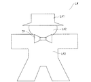
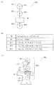
- FIG. 2 is a diagram for illustrating an example of a character represented by a line drawing.
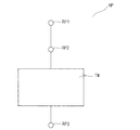
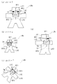
- FIG. 3 is a diagram for illustrating an example of a plurality of closed region designation pointers.
- FIG. 4 is a diagram for illustrating a state in which a plurality of closed region designation pointers are displayed on the line drawing character.
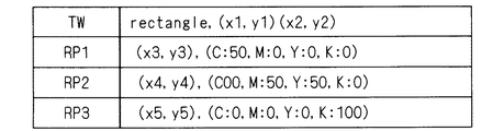
- FIG. 5 is a diagram for illustrating a data structure of a plurality of closed region designation pointers.
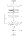
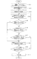
- FIG. 6 is a flowchart for explaining the operation of the area designating apparatus according to the first embodiment.
- FIG. 7 is a diagram for explaining a method for specifying a plurality of closed regions using a plurality of closed region specifying pointers.
- FIG. 1 is a diagram for explaining a configuration of an area designating apparatus according to the first embodiment.
- FIG. 2 is a diagram for illustrating an example of a character represented by a line drawing.
- FIG. 8 is a diagram for explaining the configuration of the line drawing processing apparatus according to the second embodiment.
- FIG. 9 is a flowchart for explaining the operation of the line drawing processing apparatus according to the second embodiment.
- FIG. 10 is a diagram for explaining the operation of registering the characteristic portion.
- FIG. 11 is a diagram for explaining a method for designating a plurality of closed regions using a plurality of closed region designation pointers.
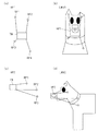
- FIG. 12 is a diagram for illustrating another example of the multiple closed region designation pointer.
- FIG. 13 is a diagram for illustrating another example of a plurality of closed region designation pointers.
- FIG. 1 is a diagram for illustrating a configuration of an area designating apparatus 1 according to the first embodiment of the present invention.
- the area specifying device 1 is a commonly used personal computer, and includes a CPU 11, a display unit 12, an input unit 13, a network I / F 14, a media drive 15, a storage unit 16, and a memory 17.
- the CPU 11 controls the entire area designating device 1.
- the CPU 11 implements each function of the area specifying device 1 by executing a program 181 in the memory 17.
- the program 181 is recorded on, for example, the media disk 18.
- the display unit 12 is used for displaying necessary information when, for example, a plurality of closed regions are designated from characters represented by line drawings.
- the input unit 13 includes a mouse and a keyboard, and is used by an operator to input an instruction to the area specifying device 1.
- the network I / F 14 is used to connect the area specifying device 1 and a network (not shown).
- the area designating apparatus 1 receives line drawing data LD for designating a plurality of closed areas from a network (not shown) via the network I / F 14.
- the program 181 that realizes the function of the area specifying device 1 may be downloaded from a server (not shown).
- the media drive 15 is used for reading the program 181 recorded on the media disk 18.
- the function of the area specifying device 1 is realized by the program 181 read by the media drive 15.
- the storage unit 16 stores the program 181 read by the media drive 15.
- the memory 17 is used as a work area when the CPU 11 executes the program 181.
- the functions of the multiple closed region designating unit 171 and the coloring unit 172 are realized in the memory 17.
- the multiple closed area designation unit 171 designates a plurality of closed areas constituting the character represented by the line drawing in the line drawing data LD according to the operation of the operator of the area designation device 1.
- FIG. 2 is a diagram for illustrating an example of a character represented by a line drawing.
- the line drawing character LW is expressed by combining a plurality of closed regions LA1, LA2, LA3 and a characteristic portion TP that is a characteristic portion for specifying the character.
- Closed areas LA1, LA2, and LA3 are closed areas for representing characters.
- the closed area LA1 represents a hat
- the closed area LA2 represents a face
- the closed area LA3 represents a body.
- a set of a plurality of closed regions expresses a character.
- the characteristic part TP is a characteristic part given to specify the character.
- the character in the manga exhibits a self-other identification function for the reader. That is, a characteristic part is often given to a character in order to identify the character.
- a “bow tie” is a characteristic part that identifies a character for distinguishing it from other characters.
- Such a part for specifying a character is a characteristic part of the character, and is used as a characteristic part TP that serves as a reference for designating a plurality of closed regions in a process described later.
- the multiple closed region designation unit 171 displays a multiple closed region designation pointer HP that can be operated by the input unit 13 on the display unit 12 in order to designate a plurality of closed regions constituting such a line drawing character LW.
- the multiple closed region designation pointer HP is used to collectively designate the feature portion TP and the multiple closed regions constituting the line drawing character LW from the line drawing character LW expressed by the line drawing data LD. Is done.
- FIG. 3 is a diagram for illustrating an example of the multiple closed region designation pointer HP.
- the multiple closed region designation pointer HP is a kind of pointer displayed on the display unit 12 and operable by the input unit 13.
- the multiple closed region designation pointer HP includes a feature portion designation window TW and a plurality of region designation points RP arranged at predetermined positions.
- the multiple closed region designation pointer HP shown in FIG. 3 includes three region designation points RP1, RP2, and RP3.
- the shape of the feature portion designation window TW is not limited to a rectangle, and the number of region designation points RP is not limited to three.
- the feature portion designation window TW is used to designate a feature portion TP in the line drawing character LW. That is, when the operator operates the input unit 13 to position the feature portion designation window TW on the line drawing character LW, the portion surrounded by the feature portion designation window TW is designated as the feature portion TP of the line drawing character LW. Is done.
- the region designation point RP is also set.
- the area designation point RP is a designation point for designating a plurality of closed areas constituting the line drawing character LW.
- the region designation point RP is disposed at a predetermined distance from the feature portion designation window TW.
- the area designation point RP1 designates the closed area LA1
- the area designation point RP2 designates the closed area LA2
- the area designation point RP3 designates the closed area LA3.
- FIG. 4 is a diagram for illustrating a state in which a plurality of closed region designation pointers HP are displayed on the line drawing character LW.
- the region designation points RP (RP1 to RP3) are respectively set. It is located on the closed areas LA1, LA2, and LA3. Therefore, each region designation point RP can designate corresponding closed regions LA1, LA2, LA3 at a time.
- the multiple closed areas are designated at a time.
- the position of each closed region designated by the multiple closed region designation pointer HP is determined around a characteristic part that identifies the character. For this reason, by using the multiple closed area designation pointer HP, a plurality of closed areas constituting a desired character are surely designated.
- a plurality of closed regions can be easily specified only by operating the multiple closed region specification pointer HP so that the feature portion TP fits in the feature portion specification window TW.
- the multiple closed region designation unit 171 includes a feature part designation window setting unit 1711, a region designation point setting unit 1712, a multiple closed region designation pointer scaling unit 1713, as a configuration related to the function of displaying the multiple closed region designation pointer HP.
- a multiple closed area designation pointer rotation unit 1714 is provided.
- the feature part designation window setting unit 1711 sets a feature part designation window TW for the feature part TP.
- a characteristic part specifying window TW is set by designating a characteristic part that identifies the character from the line drawing character LW displayed on the display unit 12.
- the operator operates the input unit 13 to draw a rectangle that includes the feature portion TP that is a characteristic portion of the line drawing.
- the feature portion designation window setting unit 1711 sets the drawn rectangle as the feature portion designation window TW.
- the shape drawn to include the feature portion TP may be not only a rectangle but also a circle or an ellipse.
- the area designation point setting unit 1712 sets a plurality of area designation points RP located at a predetermined distance from the feature portion designation window TW. That is, after the feature portion designation window TW is set, when the operator operates the input unit 13 and designates positions on a plurality of closed regions constituting the line drawing character LW, the region designation point setting unit 1712 The designated position is set as the position where the area designation point RP is arranged. In addition, when a plurality of region designation points RP are set, the region designation point setting unit 1712 sets a color to be colored in the closed region designated by the region designation point RP.
- FIG. 5 is a diagram showing the data structure of the multiple closed region designation pointer HP set by the feature portion designation window setting unit 1711 and the region designation point setting unit 1712.
- the multiple closed area designation pointer HP is composed of the characteristic part designation window TW and the multiple area designation points RP. Therefore, the multiple closed region designation pointer HP has a data structure of the feature portion designation window TW and a data structure of the region designation point RP as shown in FIG. Further, as shown in FIG. 5, the feature portion designation window TW has “rectangle” indicating that it is a rectangle, and coordinate values of two vertices.
- Each region designation point RP (RP1 to RP3) has an offset value from the barycentric point of the feature portion designation window TW and color information.
- the multiple closed area designation pointer scaling unit 1713 executes a function of changing the size of the multiple closed area designation pointer HP when a plurality of closed areas are designated. Characters are expressed in various sizes during the production of a manga, so when specifying a closed region for coloring, it is necessary to cope with changes in the size. Therefore, the multiple closed area designation pointer scaling unit 1713 sets the size of the multiple closed area designation pointer HP based on the operation of the input unit 13 by the operator so that even characters expressed in various sizes can be handled. change.
- the multiple closed area designation pointer rotation unit 1714 executes a function of rotating the multiple closed area designation pointer HP when a plurality of closed areas are designated.
- the characters are expressed at various angles during the production of the manga. Therefore, when designating a closed region for coloring, it is necessary to associate a plurality of closed region designation pointers HP with the angle of the character. Therefore, the multiple closed area designation pointer rotation unit 1714 rotates the multiple closed area designation pointer HP based on the operation of the input unit 13 by the operator so that even characters expressed at various angles can be handled.
- the coloring unit 172 performs coloring processing on a plurality of closed regions designated by the plurality of closed region designation units 171.
- Various well-known methods can be used for the coloring process for the closed region of the line drawing.
- the area designated by the multiple closed area designation pointer HP is a closed area visually, if a line break or the like actually exists and is not a closed area, line joining processing or the like is executed.
- the closed region processing may be executed.
- FIG. 6 is a flowchart for explaining the operation of the area specifying device 1.
- the area specifying device 1 acquires and displays the line drawing data LD.
- the line drawing data LD may be acquired from a network (not shown) via the network I / F unit 14. Further, as the line drawing data LD, line drawing data LD recorded on the media disk 18 may be used. Further, the line drawing data LD created by the line drawing creation function (not shown) of the area specifying device 1 may be used.
- the acquired line drawing data LD is displayed on the display unit 12. As a result, the operator can visually recognize the line drawing character LW expressed by the line drawing.
- step S2 a plurality of closed region designation pointers HP are set.
- the operator operates the input unit 13 to designate a characteristic part that identifies the displayed line drawing character LW as the characteristic part TP.
- the feature portion designation window setting unit 1711 sets a feature portion designation window TW corresponding to the feature portion TP designation processing.
- the operator operates the input unit 13 to designate a plurality of closed regions constituting the line drawing character LW.
- the area designation point setting unit 1712 sets the area designation point RP according to the closed area designation processing. Further, the operator designates a color to be colored in the closed region corresponding to each region designation point RP. As described above, the region designated point setting unit 1712 also sets the colors to be colored in each closed region when setting the plurality of region designated points RP.
- the plurality of closed region designation portions 171 designate a combination of the feature portion designation window TW and the plurality of region designation points RP as a plurality of closed region designations.
- step S3 the operator operates the input unit 13 to designate a plurality of closed regions constituting the line drawing character LW.
- the plurality of closed region designations in step S3 are basically performed using a plurality of closed region designation pointers HP as shown in FIG.
- FIG. 7 is a diagram for explaining a method for specifying a plurality of closed regions using a plurality of closed region specifying pointers HP. As shown in FIG. 7, the specification of a plurality of closed areas using the multiple closed area specification pointer HP can be applied in various ways.
- FIGS. 7A and 7B show the line drawing character LWb having a larger size than the line drawing character LW for the line drawing character LW (see FIG. 4) used when setting the multiple closed region designation pointer HP in step S2.
- FIG. 4 is a diagram for explaining a method for designating a plurality of areas constituting these characters from line drawing characters LWs having a size smaller than that of the line drawing character LW.
- the size of the plural closed area designation pointer HP is set. Has been changed.
- the size of the plurality of closed region designation pointers HP is changed by an input operation from the input unit 13 (for example, the operator presses the “ctrl” key on the keyboard of the input unit 13 while pressing the scroll wheel provided in the mouse.
- the multiple closed region designation pointer scaling unit 1713 expands the multiple closed region designation pointer HP according to the rotation operation).
- the area designating device 1 can easily designate a plurality of closed areas constituting the line drawing character LW. .
- FIG. 7C shows the line drawing character LW (see FIG. 4) used when setting the plurality of closed region designation pointers HP in step S2 from among the line drawing characters LWr in the posture in which the line drawing character LW is rotated.
- FIG. 10 is a diagram for explaining a method of designating a plurality of areas constituting the line drawing character LWr.
- FIG. 7C in order to designate a plurality of closed regions from the line drawing character LWr obtained by rotating the line drawing character LW used for setting the plurality of closed region designation pointers HP by a predetermined angle, a plurality of closed region designation pointers are designated.
- the HP angle (posture) has been changed.
- the angle of the multiple closed area designation pointer HP is changed by an input operation from the input unit 13 (for example, while the operator depresses the “shift” key on the keyboard of the input unit 13 and the scroll wheel provided in the mouse is used. This is realized by rotating the multiple closed region designation pointer HP while maintaining the aspect ratio of the multiple closed region designation pointer HP in accordance with the rotation operation).
- the rotation direction may be one direction or both directions.
- the area designating device 1 can easily set a plurality of closed areas constituting the line drawing character LW. Can be specified.
- FIG. 7D shows the line drawing character LWy (see FIG. 4) used when setting the plurality of closed region designation pointers HP in step S2, from among the line drawing characters LWy expressing the line drawing character LW sideways. It is a figure for demonstrating the method of designating the some area
- the manga character (line drawing character LWy) is expressed differently from the actual human body.
- the face of the line drawing character LWy faces sideways, the body expression does not differ greatly from the expression of the line drawing character LW at the time of setting.
- a plurality of closed areas can be designated for the line drawing character LWy by the plural closed area designation pointer HP at the time of setting.
- the area specifying device 1 easily specifies a plurality of closed areas constituting the line drawing character LW. be able to.
- step S4 it is determined whether or not a closed region has been designated for all line drawing characters LW included in the line drawing data LD. If the closed area designation has not been performed for all the line drawing characters LW, the process returns to step S3 and the closed area designation process is repeated. If the closed region designation is completed for all the line drawing characters LW, the process proceeds to step S5.
- step S5 the coloring unit 172 is colored with the color set at each area designation point RP of the plural closed area designation pointer HP. As a result, the coloring unit 172 can execute the coloring process on the closed region of each line drawing character LW without requiring an operator's operation.
- the area designating apparatus 1 shown in FIG. 1 operates as in the flowchart shown in FIG. 6, the area designating apparatus 1 can easily designate the color assigned to each closed area of the line drawing character LW. .
- FIG. 8 is a diagram for illustrating a configuration of the line drawing processing apparatus 10 according to the second embodiment of the present invention.
- the line drawing processing apparatus 10 is a commonly used personal computer, and includes a CPU 111, a display unit 112, an input unit 113, a network I / F 114, a media drive 115, a storage unit 116, and a memory 117.
- the CPU 111 controls the entire line drawing processing apparatus 10.
- the CPU 111 realizes each function of the line drawing processing apparatus 10 by executing a program 1181 in the memory 117.
- the program 1181 is recorded on the media disk 118, for example.
- the display unit 112 is used to display necessary information when, for example, a plurality of closed regions are designated from characters represented by line drawings.
- the input unit 113 includes a mouse and a keyboard, and is used by an operator to input an instruction to the line drawing processing apparatus 10.
- the network I / F 114 is used to connect the line drawing processing apparatus 10 and a network (not shown).
- the line drawing processing apparatus 10 receives line drawing data LD for designating a plurality of closed regions from a network (not shown) via the network I / F 114.
- the program 1181 for realizing the functions of the line drawing processing apparatus 10 may be downloaded from a server (not shown).
- the media drive 115 is used to read the program 1181 recorded on the media disk 118.
- the functions of the line drawing processing apparatus 10 are realized by a program 1181 read by the media drive 115.
- the storage unit 116 stores the program 1181 read by the media drive 115.
- the memory 117 is used as a work area when the CPU 11 executes the program 1181.
- a plurality of closed region designation pointer display units 1171, a feature portion registration unit 1172, a feature portion search unit 1173, and a plurality of closed region designation pointers move in the memory 117. Functions of the unit 1174, the multiple closed region designation unit 1175, and the coloring unit 1176 are realized.
- the multiple closed area designation pointer display unit 1171 displays the multiple closed area designation pointer HP on the display unit 112. By the display of the multiple closed area designation pointer HP, a plurality of closed areas constituting the character represented by the line drawing are designated in the line drawing data LD.
- the multiple closed region designation pointer display unit 1171 includes a feature portion designation window setting unit 11711 and a region designation point setting unit 11712 as components related to the function of displaying the multiple closed region designation pointer HP.
- the functions of the feature part designation window setting unit 11711 and the region designation point setting unit 11712 are the same as the functions of the feature part designation window setting unit 1711 and the region designation point setting unit 1712 described above, and will be described here. Omitted.
- the feature part registration unit 1172 registers the shape of the feature part TP of the line drawing character designated by the feature part designation window TW.
- the registered feature portion TP is used in a process to be described later for a search process of the line drawing character LW and a selection process of a plurality of closed region designation pointers HP corresponding to the searched line drawing character LW.
- the feature portion TP is designated based on an operation performed by the operator via the input unit 113.
- the feature portion search unit 1173 performs a process of searching for a line drawing character LW having the same shape as the feature portion TP registered by the feature portion registration unit 1172 from the line drawing data LD. That is, the feature portion search unit 1173 searches the line drawing character LW having a characteristic portion whose shape matches the template, using the registered shape of the feature portion TP as a template. Further, the feature portion search unit 1173 selects the multiple closed region designation pointer HP corresponding to the searched line drawing character LW.
- search by the feature portion search unit 1173 may employ other well-known techniques related to image search.
- the feature portion search unit 1173 includes a feature portion scaling unit 11731 and a feature portion rotation unit 11732, and a scaling factor for scaling the multiple closed region designation pointer HP, and An angle for rotating the multiple closed region designation pointer HP is calculated.
- the feature portion scaling unit 11731 is also referred to as a registered feature portion TP (hereinafter also simply referred to as “registered portion”) and a characteristic portion of the searched line drawing character LW (hereinafter simply referred to as “search portion”). If the size is the same but the size is not the same, the scaling factor of the size of the search portion relative to the size of the registered portion is calculated. The calculated scaling factor is used for processing in the multiple closed region designation pointer scaling unit 11741 described later.
- the feature portion rotating unit 11732 registers the registered feature portion TP and the characteristic portion of the searched line drawing character LW when the arrangement angle does not match even though the shapes match.
- the orientation (rotation angle: arrangement angle) of the search portion when the orientation is used as a reference is calculated.
- the calculated angle is used for processing in the multiple closed region designation pointer rotation unit 11742 described later.
- the feature part designation window TW is located at a characteristic part of the line drawing character LW searched by the feature part search unit 1173 (that is, a part corresponding to the registered feature part TP).
- the plural closed region designation pointer HP is moved. That is, the multiple closed region designation pointer moving unit 1174 can move the multiple closed region designation pointer HP so that the registered feature portion TP matches the searched characteristic portion of the line drawing character LW. As a result, it is possible to designate a plurality of closed regions constituting the line drawing character LW from the line drawing character LW.
- the multiple closed region designation pointer moving unit 1174 includes a multiple closed region designation pointer scaling unit 11741 and a multiple closed region designation pointer rotating unit 11742.
- the multiple closed region designation pointer scaling unit 11741 scales the multiple closed region designation pointer HP at the scaling factor obtained by the feature partial scaling unit 11731. Then, the multiple closed region designation pointer scaling unit 11741 moves the multiple closed region designation pointer HP so that the registered feature portion TP matches the characteristic portion of the searched line drawing character LW.
- the multiple closed region designation pointer rotation unit 11742 rotates the multiple closed region designation pointer HP at an angle obtained by the feature portion rotation unit 11732. Then, the multiple closed region designation pointer rotation unit 11742 moves the multiple closed region designation pointer HP so that the registered feature portion TP matches the characteristic portion of the searched line drawing character LW.
- the multiple closed area designation unit 1175 selects a plurality of closed areas constituting the searched line drawing character LW based on the area designation points RP of the multiple closed area designation pointer HP moved by the multiple closed area designation pointer moving unit 1174. Specify all at once.
- the plurality of closed regions are designated at a time using the plurality of closed region designation pointers HP.
- the position of each closed region designated by the multiple closed region designation pointer HP is determined around a characteristic part that identifies the character. For this reason, by using the multiple closed area designation pointer HP, a plurality of closed areas constituting a desired character are surely designated.
- the line drawing character LW is searched based on the registered feature portion TP, and the corresponding plural closed region designation pointer HP is selected. Therefore, the line drawing processing apparatus 10 can efficiently designate a plurality of closed regions without requiring any special operation by the operator.
- the coloring unit 1176 collectively performs the coloring process on the plurality of closed regions designated by the plurality of closed region designation units 1175.
- Various well-known methods can be used for the coloring process for the closed region of the line drawing.
- the area designated by the multiple closed area designation pointer HP is a closed area visually, if a line break or the like actually exists and is not a closed area, line joining processing or the like is executed.
- the closed region processing may be executed.
- FIG. 9 is a flowchart for explaining the operation of the line drawing processing apparatus 10.
- steps S101 and S102 are the same as those in steps S1 and S2 in the flowchart of FIG.
- step S103 the feature portion registration unit 1172 registers the feature portion TP used when the feature portion designation window TW is set (step S102).
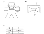
- FIG. 10 is a diagram for explaining the registration operation of the feature portion TP.
- FIG. 10A is a diagram for illustrating a state in which the feature portion designation window TW is set in step S102.
- a feature portion designation window TW and a feature portion TP are displayed on the display unit 112.
- the operator operates the input unit 113 to execute the function of the feature part registration unit 1172 in order to cause the feature part registration unit 1172 to register the feature part TP shown in FIG.
- the feature portion registration unit 1172 deletes an extra line drawing in the feature portion designation window TW in order to register the feature portion TP based on the operation of the operator.
- the extra line drawing refers to a line drawing that may cause noise when searching for another line drawing character LW using the characteristic portion TP as a template.
- the portion designated as the feature portion TP by the feature portion designation window TW is a bow tie portion of the line drawing character LW.
- the part required as the characteristic part TP is a line drawing related to the shape of the bow tie, and the other part (line drawing) is not required. Therefore, the feature part registration unit 1172 executes an extra line drawing deletion process.
- FIG. 10B is a diagram showing the feature portion TP registered by the feature portion registration unit 1172.
- line drawings other than the line required as the feature portion TP that is, the line drawing related to the shape of the bow tie
- the feature portion registration unit 1172 registers the shape of the feature portion TP.
- FIG. 10C is a diagram for illustrating the data structure of the feature portion TP registered by the feature portion registration unit 1172. As shown in FIG. 10C, as the registration data, a feature part registration ID “ID”, a feature part size “size”, and feature part actual data “DD” are stored.
- the feature part registration ID is an identification number for uniquely identifying each registered feature part TP.
- the feature part size stores the size of the feature part TP.
- the feature portion size for example, the circumscribed rectangle size of the feature portion TP is stored.
- the actual feature portion data is data indicating the shape of the feature portion TP, and is data indicating the shape of the feature portion TP, such as a bitmap format, a run length format, or a vector format.
- the feature portion actual data is used for pattern matching in feature portion search, for example.
- the feature portion search unit 1173 searches for a line drawing character LW having a shape that matches the feature portion TP registered in step S103.
- the feature portion search unit 1173 performs, for example, template matching using the shape of the registered feature portion TP as a template in order to search for an image from the line drawing data LD.
- step S105 the feature portion search unit 1173 compares the registered feature portion TP with the feature portion of the searched line drawing character LW. If a portion matching the registered feature portion TP is found (found) from the line drawing character LW, the process proceeds to step S108. On the other hand, if no search is made, the process proceeds to step S106.
- step S106 the feature portion search unit 1173 compares the shape and size of the registered feature portion TP with the feature portion of the searched line drawing character LW. If both sizes are different, but it is determined that both shapes match, the feature portion scaling unit 11731 calculates a scaling factor MG. After the calculated scaling factor MG is stored, the process proceeds to step S108. On the other hand, if the variable magnification MG has not been calculated, the process proceeds to step S107.
- step S107 the feature portion search unit 1173 compares the shape and posture (rotation angle) of the registered feature portion TP with the feature portion of the searched line drawing character LW, as in step S106. To do. If both postures are different but it is determined that both shapes match, the feature portion rotation unit 11732 calculates a rotation angle AN based on the registered posture of the feature portion TP. After the calculated rotation angle AN is stored, the process proceeds to step S108. On the other hand, when the rotation angle AN is not calculated, the process returns to step S104.
- steps S106 and S107 are sequentially performed.
- steps S106 and S107 may be reversed (that is, step S106 is executed following step S107). May be). Further, the processing of step S106 and step S107 may be performed simultaneously.
- the multiple closed region designation pointer moving unit 1174 uses the multiple closed region designation pointer HP corresponding to the feature portion TP. While selecting, the selected plural closed region designation pointer HP is moved. Thereby, a plurality of closed regions constituting the line drawing character LW are designated by the method shown in FIG. 4 (S108).
- FIG. 11 is a diagram for explaining a method for designating a plurality of closed regions using a plurality of closed region designation pointers HP. As shown in FIG. 11, the specification of a plurality of closed areas using the multiple closed area specification pointer HP can be applied in various ways.
- FIG. 4 is a diagram for explaining a method for designating a plurality of areas constituting these characters from line drawing characters LWs having a size smaller than that of the line drawing character LW.
- the size of the plural closed area designation pointer HP is set. Has been changed.
- the size of the multiple closed region designation pointer HP is changed by using the scaling factor MG previously calculated by the feature partial magnification unit 11731 by the multiple closed region designation pointer scaling unit 11741. Realized by expanding.
- the pointer scaling unit 11741 uses the scaling factor MG calculated in advance by the feature partial scaling unit 11731 to reduce the multiple closed region designation pointer HP.
- the line drawing processing apparatus 10 can easily specify a plurality of closed regions constituting the line drawing character LW. .
- FIG. 11C shows the line drawing character LWr (see FIG. 4) used when setting the multiple closed region designation pointer HP in step S102, from among the line drawing characters LWr in the posture in which the line drawing character LW is rotated.
- FIG. 10 is a diagram for explaining a method of designating a plurality of areas constituting the line drawing character LWr.
- FIG. 11C in order to designate a plurality of closed regions from the line drawing character LWr obtained by rotating the line drawing character LW used for setting the plurality of closed region designation pointers HP by a predetermined angle, a plurality of closed region designation pointers are designated.
- the HP angle (posture) has been changed.
- the angle of the multiple closed region designation pointer HP is changed by using the rotation angle AN previously calculated by the feature portion rotation unit 11732 by the multiple closed region designation pointer rotation unit 11742 and the aspect ratio of the multiple closed region designation pointer HP. This is realized by rotating the plural closed region designation pointer HP while maintaining the above.
- the rotation direction may be one direction or both directions.
- the line drawing processing apparatus 10 can easily set a plurality of closed regions constituting the line drawing character LW. Can be specified.
- FIG. 11D shows the line drawing character LWy (see FIG. 4) used when setting the plurality of closed region designation pointers HP in step S102, from among the line drawing characters LWy expressing the line drawing character LW sideways. It is a figure for demonstrating the method of designating the some area
- the manga character (line drawing character LWy) is expressed differently from the actual human body.
- the face of the line drawing character LWy faces sideways, the body expression does not differ greatly from the expression of the line drawing character LW at the time of setting.
- a plurality of closed areas can be designated for the line drawing character LWy by the plural closed area designation pointer HP at the time of setting.
- the line drawing processing apparatus 10 easily designates a plurality of closed regions constituting the line drawing character LW. be able to.
- step S109 it is determined whether or not a closed region has been designated for all line drawing characters LW included in the line drawing data LD. If the closed region designation has not been performed for all the line drawing characters LW, the process returns to step S104, and the search process based on the feature portion TP is repeated. If the closed region designation is completed for all the line drawing characters LW, the process proceeds to step S110.
- step S110 the coloring unit 1176 is colored with the color set for each area designation point RP of the multiple closed area designation pointer HP. As a result, the coloring unit 1176 can execute the coloring process on the closed region of each line drawing character LW without requiring an operator's operation.
- the line drawing processing apparatus 10 shown in FIG. 8 when the line drawing processing apparatus 10 shown in FIG. 8 operates as in the flowchart shown in FIG. 9, the line drawing processing apparatus 10 can easily specify the color assigned to each closed region of the line drawing character LW. .
- the operator can easily perform the coloring process for each of the plurality of line drawing characters LW. Therefore, the work efficiency of the coloring process is improved.
- the plural closed region designation pointer HP has been described on the assumption that the feature portion designation window TW and the region designation point RP are arranged on a straight line.
- the configuration of the plural closed region designation pointer HP is as follows. It is not limited to.
- FIG. 12 is a diagram for illustrating another example of a plurality of closed region designation pointers.
- the multiple closed region designation pointer HP1 in FIG. 12A is obtained by radially arranging a plurality of region designation points RP with respect to the feature portion designation window TW.
- the multiple closed region designation pointer HP1 shown in FIG. 12A is suitable for designating a plurality of closed regions from the line drawing character LWd1 shown in FIG. 12B, for example.
- a plurality of region designation points RP are arranged so as to be deviated in one direction with respect to the feature portion designation window TW.
- the multiple closed region designation pointer HP2 shown in FIG. 12C is suitable for designating a plurality of closed regions from the line drawing character LWd2 shown in FIG.
- the multiple closed region designation pointer HP can be configured as desired by the operator. Therefore, the coloring process for the line drawing character LW is easily executed.
- each closed region of the line drawing character LW may be designated by the region designating figure RF in a region centered on the region designated point RP (more specifically, including the region designated point RP).
- FIG. 13 is a diagram for explaining a plurality of closed region designation pointers HP3 having a plurality of region designation figures RF instead of a plurality of region designation points RP.
- FIG. 13A is a diagram for explaining the configuration of a plurality of closed region designation pointers HP3 having a plurality of region designation figures RF.
- the multiple closed region designation pointer HP3 includes a feature portion designation window TW and region designation figures RF1, RF2, and RF3 arranged at predetermined positions.
- the area designating figures RF1, RF2, and RF3 are circular areas centered on the area designating points RP1, RP2, and RP3, respectively.
- a closed region that overlaps the region specifying figure RF is specified as a region to be colored.
- FIG. 13B is a diagram for illustrating the data structure of the multiple closed region designation pointer HP3 set by the feature portion designation window setting unit 1711 (or 11711) and the region designation point setting unit 1712 (or 11712). .
- the data structure related to the feature portion designation window TW and the plurality of region designation points RP in FIG. 13B is the same as that shown in FIG.
- data related to the area designation figure RF is added. That is, “circle” is set as the area designating figure RF, and the radius “r” is also set.
- 5 (mm) is stored in the radius “r”.
- a pixel other than mm, Q, or the like may be used.
- the figure used as the area specifying figure RF may be a figure such as an ellipse or a rectangle other than a circle.
- the sizes of the area designating figures RF1, RF2, and RF3 may all be set to be the same, or may be set to different values for each area designating figure RF.
- FIG. 13C is a diagram for explaining a method of designating a closed region of the line drawing character LWx using the multiple closed region designation pointer HP3.
- the area designation point RP is deviated from the closed area constituting the line drawing character LWx.
- the closed region constituting the line drawing character LWx cannot be designated with the multiple closed region designation pointer HP as shown in FIG.
- the area designation point of the area designation figure RF1 is located outside the closed area LA1 (a person's hat corresponds).
- a part of the area designation figure RF overlaps with the closed area of the line drawing character LWx.
- a part of the area designating figure RF1 overlaps with the closed area LA1.
- a plurality of areas are designated collectively.
- the closed region to be colored is easily specified.
- the multiple closed region designation pointer HP can have a configuration desired by the operator, the coloring process for the line drawing character LW is easily performed.
Landscapes
- Physics & Mathematics (AREA)
- General Physics & Mathematics (AREA)
- Engineering & Computer Science (AREA)
- Theoretical Computer Science (AREA)
- Processing Or Creating Images (AREA)
- User Interface Of Digital Computer (AREA)
Abstract
マンガのカラー化を実現するに際して、線画により表現されるキャラクタの閉領域を容易に指定できる領域指定装置を提供する。複数閉領域指定ポインタは、特徴部分指定ウィンドウTWと、複数の領域指定点RP1~RP3と、を備える。特徴部分指定ウィンドウTWは、線画キャラクタにおける特徴部分TPを指定するために使用される。領域指定点RPは、線画キャラクタを構成する複数の閉領域LA1~LA3を指定するために使用される。オペレータの操作により、線画キャラクタの特徴部分TP上に特徴部分指定ウィンドウTWが配置されると、この配置動作にともない線画キャラクタの各閉領域LA1~LA3は、対応する領域指定点RP1~RP3により指定される。すなわち、線画キャラクタの特徴部分TPを指定するという簡便な操作だけで、線画キャラクタを構成する複数の閉領域LA1~LA3を一括して指定できる。
Description
線画で表現されており、複数の閉領域から構成されるキャラクタについて、該キャラクタの閉領域を指定する領域指定装置および領域指定プログラム、並びに該キャラクタの閉領域に対して彩色処理を行なう線画処理装置および線画処理プログラムに関する。
マンガ(Manga)とは、日本独自の風合いを持つ(モノクロ)線画で描かれたものを指す。例えば、モノクロのマンガにおける階調表現や感情表現等は、様々なトーンや掛け網、効果線、およびベタ等を使用した白黒(モノクロ)描画により実現されている。このような表現手法によって、マンガは、英語のコミック(Comic)とは異なるニュアンスを有している。
また、マンガは上述のように白黒描画されているため、マンガが出版物として印刷(出力)される場合には、通常、モノクロ印刷技術が採用される。このモノクロ印刷技術は、カラー印刷技術と比較してコスト的に有利(安価)である。
しかし、近年、電子データ化されたマンガを購読・閲覧できるサイトが急増しており、端末装置のモニタ(例えば、携帯電話の液晶モニタ)を介してマンガを鑑賞する機会が増加している。また、端末装置のモニタは、通常カラー表示可能である。したがって、モノクロマンガもカラー化(彩色、Coloring)することが求められるようになっている。
特に、日本国外には、上述したモノクロマンガの文化がほとんどない。したがって、日本国外において紙を含めた出版ビジネスを展開するためには、マンガのカラー化が必要となる。
また、マンガには、人物等のキャラクタが多数描かれている。そのため、キャラクタに対する彩色作業を繰り返すことが必要となる。例えば、1コマに平均して1~2名のキャラクタが登場する場合、1ページにはだいたい5~10個程キャラクタが登場する。従って、連載を10話程度まとめた単行本1冊には、のべ1000個以上のキャラクタが描画されており、すべてのキャラクタに対して彩色作業を行うことが必要となる。特に、人間は、知覚的に顔の違いを敏感に見分けることができるため、キャラクタの顔の彩色には一定した品質が求められている。
このように、マンガをカラー化するためには彩色作業が必要となるところ、線画に対して彩色処理を行なう技術自体は、従来より知られている(例えば、特許文献1)。
しかしながら、特許文献1の技術では、未彩色線画の各領域に彩色すべき色は、彩色済画像の領域および未彩色の線画の領域について、両領域の重心および外接矩形サイズを比較することにより決定される。
すなわち、特許文献1の技術は、彩色済画像と比較しなければ、未彩色のキャラクタに彩色処理を行なうことはできないという問題を有している。その結果、キャラクタに対して繰り返し彩色処理を実行することが必要となるマンガのカラー化に、特許文献1の技術を適用することは適切でない。
また前述のように、キャラクタの顔の彩色には一定した品質が求められている。そのため、マンガのカラー化において、同一のキャラクタには、同一の彩色処理を施す必要がある。
そこで、本発明の目的は、マンガのカラー化を実現するに際して、線画により表現されるキャラクタの閉領域を容易に指定できる領域指定装置を提供することである。
また、マンガのカラー化を実現するに際して、線画により表現されるキャラクタの閉領域に対して効率良く彩色する線画処理装置を提供することである。
上記の課題を解決するため、請求項1の発明は、線画で表現されており、複数の閉領域から構成されるキャラクタについて、該キャラクタの閉領域を指定する領域指定装置であって、表示手段と、前記表示手段に表示された前記キャラクタ上に配置された複数閉領域指定ポインタによって、前記キャラクタの特徴部分と、前記キャラクタの閉領域とを一括して指定する複数閉領域指定手段とを備え、前記複数閉領域指定ポインタは、前記キャラクタの前記特徴部分を指定する特徴部分指定ウィンドウと、前記特徴部分指定ウィンドウを基準として所定の位置に配置されており、前記キャラクタの閉領域を指定する複数の領域指定点とを有することを特徴とする。
また、請求項2の発明は、請求項1に記載の領域指定装置において、前記複数閉領域指定部は、前記キャラクタの前記特徴部分に対して前記特徴部分指定ウィンドウを対応させる特徴部分指定ウィンドウ設定手段と、前記複数の領域指定点を設定する領域指定点設定手段とを有することを特徴とする。
また、請求項3の発明は、請求項2に記載の領域指定装置において、前記領域指定点設定手段は前記複数の領域指定点を設定するに際し、各領域指定点により指定される閉領域に彩色される色を設定することを特徴とする。
また、請求項4の発明は、請求項2に記載の領域指定装置において、領域指定図形は、前記複数の領域指定点のうちの対応する領域指定点を中心として設定される図形であり、前記複数領域指定手段は、各領域指定図形と重複する閉領域を一括して指定することを特徴とする。
また、請求項5の発明は、請求項1に記載の領域指定装置において、前記複数閉領域指定手段は、複数閉領域指定ポインタの拡大乃至縮小操作が可能であることを特徴とする。
また、請求項6の発明は、請求項1に記載の領域指定装置において、前記複数閉領域指定手段は、複数閉領域指定ポインタの回転操作が可能であることを特徴とする。
また、請求項7の発明は、線画処理装置であって、請求項1に記載の領域指定装置を使用して、線画で表現されており、複数の閉領域から構成されるキャラクタに対して彩色処理を行なうことを特徴とする。
また、請求項8の発明は、線画で表現されており、複数の閉領域から構成されるキャラクタについて、該キャラクタに対して彩色処理を行なう線画処理装置であって、表示手段と、前記キャラクタの特徴部分を指定する特徴部分指定ウィンドウと、前記特徴部分指定ウィンドウを基準として所定の位置に配置されており、前記キャラクタの閉領域を指定する複数の領域指定点とを有する複数閉領域指定ポインタを、前記表示手段に表示させる複数閉領域指定ポインタ表示手段と、前記特徴部分指定ウィンドウにより指定される前記キャラクタの特徴部分を登録する特徴部分登録手段と、前記表示手段に表示される線画から、前記特徴部分登録手段により登録された特徴部分と同様の形状を有するキャラクタを検索する特徴部分検索手段と、前記特徴部分検索手段により検索されたキャラクタの部分のうち、前記特徴部分登録手段により登録された特徴部分に対応する部分に、前記特徴部分指定ウィンドウが位置するよう、前記複数閉領域指定ポインタを移動させるポインタ移動手段と、前記ポインタ移動手段により移動させられた前記複数閉領域指定ポインタの各領域指定点に基づいて、前記特徴部分検索手段により検索されたキャラクタの閉領域を一括して指定する複数閉領域指定手段と、前記複数閉領域指定手段により一括して指定された閉領域に対して彩色処理を実行する彩色手段とを備えることを特徴とする。
また、請求項9の発明は、請求項8に記載の線画処理装置において、複数閉領域指定ポインタ表示手段は、前記キャラクタの前記特徴部分に対して前記特徴部分指定ウィンドウを対応させる特徴部分指定ウィンドウ設定手段と、前記複数の領域指定点を設定する領域指定点設定手段とを有することを特徴とする。
また、請求項10の発明は、請求項9に記載の線画処理装置において、前記領域指定点設定手段は、前記複数の領域指定点を設定するに際し、各領域指定点により指定される閉領域に彩色される色を設定することを特徴とする。
また、請求項11の発明は、請求項9に記載の線画処理装置において、領域指定図形は、前記複数の領域指定点のうちの対応する領域指定点を中心として設定される図形であり、前記複数閉領域指定ポインタ表示手段は、各領域指定図形と重複する閉領域を一括して指定することを特徴とする。
また、請求項12の発明は、請求項8に記載の線画処理装置において、前記ポインタ移動手段は、前記特徴部分登録手段により登録されている特徴部分と、前記特徴部分検索手段により検索されたキャラクタの特徴的な部分と、が一致するように前記複数閉領域指定ポインタを変倍および移動させる複数閉領域指定ポインタ変倍手段、を有することを特徴とする。
また、請求項13の発明は、請求項8に記載の線画処理装置において、前記ポインタ移動手段は、前記特徴部分登録手段により登録されている特徴部分と、前記特徴部分検索手段により検索されたキャラクタの特徴的な部分と、が一致するように前記複数閉領域指定ポインタを回転および移動させる複数閉領域指定ポインタ回転手段、を有することを特徴とする。
また、請求項14の発明は、線画で表現されており、複数の閉領域から構成されるキャラクタについて、該キャラクタの閉領域を指定する処理を実行するコンピュータ読み取り可能な領域指定プログラムであって、前記コンピュータによる前記領域指定プログラムの実行は、前記コンピュータに、表示手段に前記キャラクタを表示させる表示ステップと、前記表示手段に表示されており、前記キャラクタ上に配置された複数閉領域指定ポインタによって、前記キャラクタの特徴部分と、前記キャラクタの閉領域とを一括して指定する複数閉領域指定ステップとを実行させ、前記複数閉領域指定ポインタは、前記キャラクタの前記特徴部分を指定する特徴部分指定ウィンドウと、前記特徴部分指定ウィンドウを基準として所定の位置に配置されており、前記キャラクタの閉領域を指定する複数の領域指定点とを有することを特徴とする。
また、請求項15の発明は、線画で表現されており、複数の閉領域から構成されるキャラクタについて、該キャラクタの閉領域に対して彩色処理を行なうコンピュータ読み取り可能な線画処理プログラムであって、前記コンピュータによる前記線画処理プログラムの実行は、前記コンピュータに、表示手段に前記キャラクタを表示させる表示ステップと、前記キャラクタの特徴部分を指定する特徴部分指定ウィンドウと、前記特徴部分指定ウィンドウを基準として所定の位置に配置されており、前記キャラクタの閉領域を指定する複数の領域指定点とを有する複数閉領域指定ポインタを、前記表示手段に表示させる複数閉領域指定ポインタ表示ステップと、前記特徴部分指定ウィンドウにより指定される前記キャラクタの特徴部分を登録する特徴部分登録ステップと、前記表示手段に表示される線画から、前記特徴部分登録ステップにより登録された特徴部分と同様の形状を有するキャラクタを検索する特徴部分検索ステップと、前記特徴部分検索ステップにより検索されたキャラクタの部分のうち、前記特徴部分登録ステップにより登録された特徴部分に対応する部分に、前記特徴部分指定ウィンドウが位置するよう、前記複数閉領域指定ポインタを移動させるポインタ移動ステップと、前記ポインタ移動ステップにより移動させられた前記複数閉領域指定ポインタの各領域指定点に基づいて、前記特徴部分検索ステップにより検索されたキャラクタの閉領域を一括して指定する複数閉領域指定ステップと、前記複数閉領域指定ステップにより一括して指定された閉領域に対して彩色処理を実行する彩色ステップとを実行させることを特徴とする。
請求項1ないし請求項7に記載の発明によれば、オペレータの操作により、キャラクタの特徴部分の上に特徴部分指定ウィンドウが配置されると、この配置動作にともないキャラクタの各閉領域が、対応する領域指定点により指定される。すなわち、キャラクタの特徴部分を指定するという簡便な操作だけで、キャラクタを構成する複数の領域を一括して指定できる。そのため、使用者は、キャラクタの各閉領域を容易に指定でき、使用者のキャラクタ指定負担を軽減させることができる。
特に、請求項7に記載の発明によれば、キャラクタの各閉領域を容易に指定する処理、および、指定された閉領域に彩色する処理を、効率よく実行することができる。
また、請求項8ないし請求項13に記載の発明によれば、登録された特徴部分と同様の形状を有するキャラクタが検索されると、ポインタ移動手段は、検索されたキャラクタの部分のうち特徴部分登録手段により登録された特徴部分に対応する部分に特徴部分指定ウィンドウが位置するよう、複数閉領域指定ポインタを移動させる。また、複数閉領域指定ポインタの移動にともなって、各領域指定点は、検索されたキャラクタの各閉領域を指定する。そのため、オペレータの特段の操作を必要とすることなしに、効率的に複数の閉領域を一括して指定し、指定された各閉領域を彩色することができる。
また、請求項14に記載の発明によれば、領域指定プログラムが読み込まれたコンピュータを、請求項1の領域指定装置として使用することができる。
さらに、請求項15に記載の発明によれば、線画処理プログラムが読み込まれたコンピュータを、請求項8の線画処理装置として使用することができる。
以下、図面を利用しながら、本発明を実施するための最良の形態について、説明を行なう。
<第1の実施の形態>
図1は、本発明の第1の実施の形態における領域指定装置1の構成を示すための図である。領域指定装置1は、一般的に使用されているパーソナルコンピュータであり、CPU11、表示部12、入力部13、ネットワークI/F14、メディアドライブ15、記憶部16、およびメモリ17を有している。
図1は、本発明の第1の実施の形態における領域指定装置1の構成を示すための図である。領域指定装置1は、一般的に使用されているパーソナルコンピュータであり、CPU11、表示部12、入力部13、ネットワークI/F14、メディアドライブ15、記憶部16、およびメモリ17を有している。
CPU11は、領域指定装置1全体を制御する。CPU11は、メモリ17においてプログラム181を実行することによって、領域指定装置1の各機能を実現している。ここで、プログラム181は、例えばメディアディスク18に記録されている。
表示部12は、例えば線画により表現されるキャラクタの中から複数の閉領域が指定される場合において、必要な情報を表示するために使用される。入力部13は、マウスやキーボードで構成されており、オペレータが領域指定装置1に対して指示を入力するために使用される。
ネットワークI/F14は、領域指定装置1と、ネットワーク(図示省略)と、を接続するために使用される。領域指定装置1は、ネットワークI/F14を介して、ネットワーク(図示省略)から複数の閉領域を指定するための線画データLDを受信する。また、本実施の形態において、領域指定装置1の機能を実現するプログラム181は、サーバ(図示省略)よりダウンロードされるようにしてもよい。
メディアドライブ15は、メディアディスク18に記録されているプログラム181を読み取るために使用される。そして、領域指定装置1の機能は、メディアドライブ15で読み取られたプログラム181により実現される。
記憶部16は、メディアドライブ15で読み取られたプログラム181を格納する。メモリ17は、CPU11がプログラム181を実行する際に、ワークエリアとして使用される。メモリ17にプログラム181が読み込まれ、CPU11によりプログラム181が実行されることによって、メモリ17において複数閉領域指定部171および彩色部172の機能が実現される。
複数閉領域指定部171は、領域指定装置1のオペレータの操作にしたがって、線画データLDにおいて、線画により表現されるキャラクタを構成する複数の閉領域を指定する。
図2は、線画により表現されるキャラクタの一例を示すための図である。図2に示すように、線画キャラクタLWは、複数の閉領域LA1、LA2、LA3と、キャラクタを特定する特徴的な部分である特徴部分TPと、が組み合わされることによって表現されている。
閉領域LA1、LA2、LA3は、それぞれキャラクタを表現するための閉領域である。例えば、閉領域LA1は帽子を、閉領域LA2は顔を、閉領域LA3は胴体を、それぞれ表現しておいる。そして、複数の閉領域の集合がキャラクタを表現する。
特徴部分TPは、キャラクタを特定するために付与される特徴的な部分である。ここで、マンガにおけるキャラクタは、読者に対する自他識別機能を発揮する。すなわち、キャラクタには、そのキャラクタを特定するため、特徴的なパーツが付与されることが多い。例えば、図2においては、「蝶ネクタイ」が、他のキャラクタと区別するためのキャラクタを特定する特徴的な部分である。このようなキャラクタを特定するためのパーツは、キャラクタの特徴的な部分であり、後述するプロセスにおいて複数の閉領域を指定するための基準となる特徴部分TPとして使用される。
複数閉領域指定部171は、このような線画キャラクタLWを構成する複数の閉領域を指定するために、入力部13によって操作可能な複数閉領域指定ポインタHPを表示部12に表示する。ここで、複数閉領域指定ポインタHPは、線画データLDにより表現された線画キャラクタLWから、特徴部分TPと、該線画キャラクタLWを構成する複数の閉領域と、を一括して指定するために使用される。
図3は、複数閉領域指定ポインタHPの一例を示すための図である。複数閉領域指定ポインタHPは、表示部12に表示され入力部13によって操作可能なポインタの一種である。
複数閉領域指定ポインタHPは、特徴部分指定ウィンドウTWと、所定の位置に配置された複数の領域指定点RPと、を備えている。例えば、図3に示す複数閉領域指定ポインタHPは、3つの領域指定点RP1、RP2、RP3を備えている。なお、特徴部分指定ウィンドウTWの形状は矩形に限定されず、領域指定点RPの数は3つに限定されることはない。
特徴部分指定ウィンドウTWは、線画キャラクタLWにおける特徴部分TPを指定するために使用される。すなわち、オペレータが、入力部13を操作して、線画キャラクタLW上に特徴部分指定ウィンドウTWを位置させると、該特徴部分指定ウィンドウTWで囲まれる部分が、該線画キャラクタLWの特徴部分TPとして指定される。また、特徴部分TPを指定するために特徴部分指定ウィンドウTWが設定されると、併せて領域指定点RPも設定される。
領域指定点RPは、線画キャラクタLWを構成する複数の閉領域を指定するための指定点である。領域指定点RPは、特徴部分指定ウィンドウTWから所定の距離の位置に配置される。例えば、図3においては、領域指定点RP1が閉領域LA1を、領域指定点RP2が閉領域LA2を、領域指定点RP3が閉領域LA3を、それぞれ指定する。
図4は、複数閉領域指定ポインタHPを線画キャラクタLW上に表示した状態を示すための図である。図4に示すように、オペレータが入力部13を操作して、特徴部分指定ウィンドウTWが線画キャラクタLW上の特徴部分TPに位置させられると、各領域指定点RP(RP1~RP3)が、それぞれ閉領域LA1、LA2、LA3上に位置することになる。そのため、各領域指定点RPは、対応する閉領域LA1、LA2、LA3を一度に指定できる。
この複数閉領域指定ポインタHPを使用した複数の閉領域指定において、複数の閉領域は、一度に指定される。また、複数閉領域指定ポインタHPにより指定される各閉領域の位置は、キャラクタを特定する特徴的な部分を中心として決定される。そのため、複数閉領域指定ポインタHPを使用することによって、所望するキャラクタを構成する複数の閉領域が確実に指定される。また、特徴部分指定ウィンドウTW内に特徴部分TPが収まるように、複数閉領域指定ポインタHPがアバウトに操作されるだけで、複数の閉領域が容易に指定される。
また、複数閉領域指定部171は、複数閉領域指定ポインタHPを表示する機能に関わる構成として、特徴部分指定ウィンドウ設定部1711、領域指定点設定部1712、複数閉領域指定ポインタ変倍部1713、および複数閉領域指定ポインタ回転部1714を備えている。
特徴部分指定ウィンドウ設定部1711は、特徴部分TPに対する特徴部分指定ウィンドウTWを設定する。入力部13からの操作にしたがい、表示部12に表示された線画キャラクタLWから、該キャラクタを特定する特徴的な部分が指定されることによって、特徴部分指定ウィンドウTWの設定が行なわれる。特徴部分指定ウィンドウTWの設定方法としては、オペレータが入力部13を操作し、線画の特徴的な部分である特徴部分TPを内包するような矩形を描画させる。そして、特徴部分指定ウィンドウ設定部1711は、該描画された矩形を特徴部分指定ウィンドウTWとして設定する。この時、特徴部分TPを内包するために描画される形状は、矩形のみならず円や楕円などでもよい。
領域指定点設定部1712は、特徴部分指定ウィンドウTWから所定の距離に位置する複数の領域指定点RPを設定する。すなわち、特徴部分指定ウィンドウTWが設定された後において、オペレータが、入力部13を操作し、線画キャラクタLWを構成する複数の閉領域上の位置を指定すると、領域指定点設定部1712は、該指定された位置を領域指定点RPが配置される位置として設定する。また、領域指定点設定部1712は、複数の領域指定点RPの設定が行なわれる際、該領域指定点RPによって指定される閉領域に彩色される色の設定を行なう。
図5は、特徴部分指定ウィンドウ設定部1711および領域指定点設定部1712により設定された複数閉領域指定ポインタHPのデータ構造を示すための図である。複数閉領域指定ポインタHPは、前述のとおり、特徴部分指定ウィンドウTWと複数の領域指定点RPとから構成されている。そのため、複数閉領域指定ポインタHPは、図5に示すように特徴部分指定ウィンドウTWのデータ構造と、領域指定点RPのデータ構造と、を有している。また、図5に示すように、特徴部分指定ウィンドウTWは、矩形であることを示す「rectangle」と、2頂点の座標値と、を有している。また、各領域指定点RP(RP1~RP3)は、特徴部分指定ウィンドウTWの重心点からのオフセット値と、色情報と、を有している。
図1に戻って、複数閉領域指定ポインタ変倍部1713は、複数の閉領域が指定されるる場合において、複数閉領域指定ポインタHPのサイズを変更する機能を実行する。キャラクタは、マンガの作中において様々な大きさで表現されるので、彩色のための閉領域の指定を行なう場合、そのサイズの変化に対応する必要がある。そこで、様々なサイズで表現されたキャラクタであっても対応できるように、複数閉領域指定ポインタ変倍部1713は、オペレータによる入力部13の操作に基づいて、複数閉領域指定ポインタHPのサイズを変更する。
複数閉領域指定ポインタ回転部1714は、複数の閉領域が指定される場合において、複数閉領域指定ポインタHPを回転する機能を実行する。ここで、キャラクタは、マンガの作中において様々な角度で表現されている。そのため、彩色のための閉領域の指定を行なう場合、キャラクタの角度に複数閉領域指定ポインタHPを対応させる必要がある。そこで、様々な角度で表現されたキャラクタであっても対応できるように、複数閉領域指定ポインタ回転部1714は、オペレータによる入力部13の操作に基づいて、複数閉領域指定ポインタHPを回転する。
彩色部172は、複数閉領域指定部171で指定された複数の閉領域に対して、彩色処理を行なう。線画の閉領域に対する彩色処理は周知の様々な手法を使用することが可能である。また、複数閉領域指定ポインタHPにより指定された領域が、目視上は閉領域であっても、実際には線切れ等が存在して閉領域ではなかった場合、線繋ぎ処理などが実行され、閉領域化処理が実行されるようにしてもよい。
図6は、領域指定装置1の動作を説明するためのフローチャートである。まず、ステップS1において、領域指定装置1は、線画データLDを取得および表示する。ここで、線画データLDは、ネットワークI/F部14を介して、ネットワーク(図示省略)から取得されてもよい。また、線画データLDとしては、メディアディスク18に記録されている線画データLDが使用されてもよい。さらに、領域指定装置1の線画作成機能(図示省略)により作成された線画データLDが使用されてもよい。取得された線画データLDは、表示部12に表示される。その結果、オペレータは、線画で表現された線画キャラクタLWを視認することが可能となる。
次に、ステップS2において、複数閉領域指定ポインタHPの設定が行なわれる。オペレータは、入力部13を操作して、表示された線画キャラクタLWを特定する特徴的な部分を特徴部分TPとして指定する。特徴部分指定ウィンドウ設定部1711は、該指定に基づいて、特徴部分TPの指定処理に応じた特徴部分指定ウィンドウTWを設定する。
特徴部分指定ウィンドウTWの設定に続けて、オペレータは、入力部13を操作して、線画キャラクタLWを構成する複数の閉領域を指定する。領域指定点設定部1712は、該指定に基づいて、閉領域指定処理に応じて領域指定点RPを設定する。また、オペレータは、各領域指定点RPに対応する閉領域に彩色したい色を指定する。このように、領域指定点設定部1712は、複数の領域指定点RPを設定するに際し、各閉領域に彩色されるべき色を併せて設定する。
特徴部分指定ウィンドウTWと複数の領域指定点RPと、が設定されたならば、複数閉領域指定部171は、該特徴部分指定ウィンドウTWと複数の領域指定点RPとの組合せを複数閉領域指定ポインタHPとして設定する。そして、設定された複数閉領域指定ポインタHPは、以降の閉領域指定処理に使用される。
続いて、ステップS3において、オペレータは、入力部13を操作して、線画キャラクタLWを構成する複数の閉領域を指定する。ステップS3における複数の閉領域指定は、基本的には、図4に示したように、複数閉領域指定ポインタHPを使用して行なわれる。
図7は、複数閉領域指定ポインタHPを使用した複数の閉領域の指定手法を説明するための図である。図7に示すように、複数閉領域指定ポインタHPを使用した複数の閉領域の指定は、様々な応用が可能である。
図7(a)、(b)は、ステップS2において複数閉領域指定ポインタHPを設定する際に使用された線画キャラクタLW(図4参照)について、該線画キャラクタLWよりもサイズが大きい線画キャラクタLWb、または、該線画キャラクタLWよりもサイズが小さい線画キャラクタLWs、の中から、これらキャラクタを構成する複数の領域を指定する手法を説明するための図である。
図7(a)では、複数閉領域指定ポインタHPの設定時に使用された線画キャラクタLWよりもサイズの大きい線画キャラクタLWbの中から複数の閉領域を指定するため、複数閉領域指定ポインタHPのサイズが変更されている。ここで、複数閉領域指定ポインタHPのサイズ変更は、入力部13からの入力操作(例えば、オペレータが入力部13のキーボード上の「ctrl」キーを押下しながら、マウスに備えられたスクロールホイールを回転させる操作)に応じ、複数閉領域指定ポインタ変倍部1713が複数閉領域指定ポインタHPを拡大することによって、実現される。
また、複数閉領域指定ポインタHPの設定時に使用された線画キャラクタLWよりもサイズの小さい線画キャラクタLWsの中から複数の閉領域が指定される場合(図7(b)参照)、オペレータは、入力部13のキーボード上の「ctrl」キーを押下しながら、マウスに備えられたスクロールホイールを拡大時とは逆方向に回転させる。この操作に応じて、複数閉領域指定ポインタ変倍部1713は、複数閉領域指定ポインタHPを縮小する。
従って、同種の線画キャラクタのサイズが、マンガの作中に登場するごとに異なっていたとしても、領域指定装置1は、線画キャラクタLWを構成する複数の閉領域を、容易に指定することができる。
図7(c)は、ステップS2において複数閉領域指定ポインタHPを設定する際に使用された線画キャラクタLW(図4参照)について、該線画キャラクタLWを回転させた姿勢の線画キャラクタLWrの中から、該線画キャラクタLWrを構成する複数の領域を指定する手法を説明するための図である。
図7(c)では、複数閉領域指定ポインタHPの設定時に使用された線画キャラクタLWを所定の角度だけ回転させた線画キャラクタLWrの中から複数の閉領域を指定するため、複数閉領域指定ポインタHPの角度(姿勢)が変更されている。ここで、複数閉領域指定ポインタHPの角度変更は、入力部13からの入力操作(例えば、オペレータが入力部13のキーボード上の「shift」キーを押下しながら、マウスに備えられたスクロールホイールを回転させる操作)に応じ、複数閉領域指定ポインタ回転部1714が複数閉領域指定ポインタHPの縦横比を維持したまま複数閉領域指定ポインタHPを回転させることによって、実現される。また、回転方向は、一方向のみでも、両方向にも回転できるようにしてもよい。
このように、同種の線画キャラクタの角度(姿勢)が、マンガの作中に登場するごとに異なっていたとしても、領域指定装置1は、線画キャラクタLWを構成する複数の閉領域を、容易に指定することができる。
図7(d)は、ステップS2において複数閉領域指定ポインタHPを設定する際に使用された線画キャラクタLW(図4参照)について、該線画キャラクタLWを横向きに表現した線画キャラクタLWyの中から、該線画キャラクタLWyを構成する複数の領域を指定する手法を説明するための図である。
ここで、複数閉領域指定ポインタHPの設定時に使用された線画キャラクタLWが、横向きの線画キャラクタLWyとして表現される場合、マンガのキャラクタ(線画キャラクタLWy)は、実際の人体とは異なる表現がされることが多い。例えば、図7(d)に示すように、線画キャラクタLWyの顔は横を向いているにも関わらず、身体の表現は設定時の線画キャラクタLWの表現と大きく異なる部分がない。このような場合であれば、設定時の複数閉領域指定ポインタHPによって、線画キャラクタLWyに対しても複数の閉領域指定が可能である。
このように、同種の線画キャラクタの向きが、マンガの作中に登場するごとに多少異なっていたとしても、領域指定装置1は、線画キャラクタLWを構成する複数の閉領域を、容易に指定することができる。
なお、図7の説明では、複数閉領域指定ポインタHPを拡大、縮小、または回転させる動作を別々に説明したが、これらの動作は同時に行われてもよい。
続いて、ステップS4において、線画データLDに含まれる全ての線画キャラクタLWに対して閉領域指定が行なわれたか否かの判定が実行される。全ての線画キャラクタLWに対して閉領域指定が行なわれていない場合には、ステップS3に戻り、閉領域指定処理を繰り返す。そして、全ての線画キャラクタLWについて閉領域指定が終了したならば、ステップS5へ進む。
ステップS5において、彩色部172は、複数閉領域指定ポインタHPの各領域指定点RPに設定された色で彩色される。これにより、彩色部172は、オペレータの操作を必要とせずに、各線画キャラクタLWの閉領域に対して彩色処理を実行できる。
このように、図1に示した領域指定装置1が図6に示したフローチャートのように動作すると、領域指定装置1は、線画キャラクタLWの各閉領域に付される色を、容易に指定できる。
<第2の実施の形態>
第1の実施の形態において、線画キャラクタLWを構成する複数の閉領域の指定は、オペレータが作った入力部13の入力動作に応じて、複数閉領域指定ポインタHPにより行われるものとして説明した。しかしながら、複数の閉領域を指定する技術は、第1の実施の形態のものに限定されない。
第1の実施の形態において、線画キャラクタLWを構成する複数の閉領域の指定は、オペレータが作った入力部13の入力動作に応じて、複数閉領域指定ポインタHPにより行われるものとして説明した。しかしながら、複数の閉領域を指定する技術は、第1の実施の形態のものに限定されない。
図8は、本発明の第2の実施の形態における線画処理装置10の構成を示すための図である。線画処理装置10は、一般的に使用されているパーソナルコンピュータであり、CPU111、表示部112、入力部113、ネットワークI/F114、メディアドライブ115、記憶部116、およびメモリ117を有している。
CPU111は、線画処理装置10全体を制御する。CPU111は、メモリ117においてプログラム1181を実行することによって、線画処理装置10の各機能を実現している。ここで、プログラム1181は、例えばメディアディスク118に記録されている。
表示部112は、例えば線画により表現されるキャラクタの中から複数の閉領域が指定される場合において、必要な情報を表示するために使用される。入力部113は、マウスやキーボードで構成されており、オペレータが線画処理装置10に対して指示を入力するために使用される。
ネットワークI/F114は、線画処理装置10と、ネットワーク(図示省略)と、を接続するために使用される。線画処理装置10は、ネットワークI/F114を介して、ネットワーク(図示省略)から複数の閉領域を指定するための線画データLDを受信する。また、本実施の形態において、線画処理装置10の機能を実現するプログラム1181は、サーバ(図示省略)よりダウンロードされるようにしてもよい。
メディアドライブ115は、メディアディスク118に記録されているプログラム1181を読み取るために使用される。そして、線画処理装置10の機能は、メディアドライブ115で読み取られたプログラム1181により実現される。
記憶部116は、メディアドライブ115で読み取られたプログラム1181を格納する。メモリ117は、CPU11がプログラム1181を実行する際に、ワークエリアとして使用される。メモリ117にプログラム1181が読み込まれ、CPU111によりプログラム1181が実行されることによって、メモリ117において複数閉領域指定ポインタ表示部1171、特徴部分登録部1172、特徴部分検索部1173、複数閉領域指定ポインタ移動部1174、複数閉領域指定部1175、および彩色部1176の機能が実現される。
複数閉領域指定ポインタ表示部1171は、複数閉領域指定ポインタHPを表示部112に表示させる。この複数閉領域指定ポインタHPの表示により、線画データLDにおいて、線画により表現されるキャラクタを構成する複数の閉領域が指定される。
なお、線画データLDにおける線画キャラクタLWは、先に説明を行なったものと同様なものなので、ここでは説明を省略する。また、複数閉領域指定ポインタHPも、先に説明を行なったものと同様なものなので、ここでは説明を省略する。
複数閉領域指定ポインタ表示部1171は、複数閉領域指定ポインタHPを表示する機能に関わる構成として、特徴部分指定ウィンドウ設定部11711と、領域指定点設定部11712と、を備えている。特徴部分指定ウィンドウ設定部11711、および領域指定点設定部11712の機能は、先に説明を行なった特徴部分指定ウィンドウ設定部1711、および領域指定点設定部1712の機能と同様なので、ここでは説明を省略する。
特徴部分登録部1172は、特徴部分指定ウィンドウTWにより指定される線画キャラクタの特徴部分TPの形状を登録する。登録された特徴部分TPは、後述するプロセスにおいて、線画キャラクタLWの検索処理、および検索された線画キャラクタLWに対応する複数閉領域指定ポインタHPの選択処理に使用される。なお、特徴部分TPは、入力部113を介してオペレータが行う操作に基づいて、指定される。
特徴部分検索部1173は、線画データLDから、特徴部分登録部1172で登録された特徴部分TPと同様の形状を有する線画キャラクタLWを検索する処理を行なう。すなわち、特徴部分検索部1173は、登録された特徴部分TPの形状をテンプレートとして、該テンプレートと形状が一致する特徴的な部分を有する線画キャラクタLWを検索する。また、特徴部分検索部1173は、検索された線画キャラクタLWに対応する複数閉領域指定ポインタHPを選択する。
なお、特徴部分検索部1173による検索は、他の画像検索に関わる周知技術を採用してもよい。
図8に示すように、特徴部分検索部1173は、特徴部分変倍部11731と、特徴部分回転部11732と、を備えており、複数閉領域指定ポインタHPを変倍するための変倍率、および複数閉領域指定ポインタHPを回転させるための角度を演算する。
特徴部分変倍部11731は、登録されている特徴部分TP(以下、単に、「登録部分」とも呼ぶ)と、検索された線画キャラクタLWの特徴的な部分(以下、単に、「検索部分」とも呼ぶ)と、について、形状が一致していても、サイズが一致していない場合に、登録部分のサイズに対する検索部分のサイズの変倍率を演算する。演算された変倍率は、後述する複数閉領域指定ポインタ変倍部11741での処理に使用される。
特徴部分回転部11732は、登録された特徴部分TPと、検索された線画キャラクタLWの特徴的な部分と、について、形状が一致していても、配置角度が一致していない場合に、登録部分の姿勢を基準とした時の検索部分の姿勢(回転角度:配置角度)を演算する。演算された角度は、後述する複数閉領域指定ポインタ回転部11742での処理に使用される。
複数閉領域指定ポインタ移動部1174は、特徴部分検索部1173により検索された線画キャラクタLWの特徴的な部分(すなわち、登録された特徴部分TPに対応する部分)に特徴部分指定ウィンドウTWが位置するよう、複数閉領域指定ポインタHPを移動させる。すなわち、複数閉領域指定ポインタ移動部1174は、登録された特徴部分TPと線画キャラクタLWの検索された特徴的な部分とが一致するように、複数閉領域指定ポインタHPを移動させることができる。これにより、線画キャラクタLWの中から、該線画キャラクタLWを構成する複数の閉領域を指定することが、可能となる。
図8に示すように、複数閉領域指定ポインタ移動部1174は、複数閉領域指定ポインタ変倍部11741と、複数閉領域指定ポインタ回転部11742と、を備えている。
複数閉領域指定ポインタ変倍部11741は、特徴部分変倍部11731にて求められた変倍率で、複数閉領域指定ポインタHPを変倍する。そして、複数閉領域指定ポインタ変倍部11741は、登録された特徴部分TPと、検索された線画キャラクタLWの特徴的な部分と、が一致するように、複数閉領域指定ポインタHPを移動させる。
複数閉領域指定ポインタ回転部11742は、特徴部分回転部11732にて求められた角度で、複数閉領域指定ポインタHPを回転させる。そして、複数閉領域指定ポインタ回転部11742は、登録された特徴部分TPと、検索された線画キャラクタLWの特徴的な部分と、が一致するように、複数閉領域指定ポインタHPを移動させる。
複数閉領域指定部1175は、複数閉領域指定ポインタ移動部1174により移動された複数閉領域指定ポインタHPの各領域指定点RPに基づいて、検索された線画キャラクタLWを構成する複数の閉領域を一括して指定する。
このように、複数閉領域指定部1175により実行される複数の閉領域指定において、複数の閉領域は、複数閉領域指定ポインタHPを使用し、一度に指定される。また、複数閉領域指定ポインタHPにより指定される各閉領域の位置は、キャラクタを特定する特徴的な部分を中心として決定される。そのため、複数閉領域指定ポインタHPを使用することによって、所望するキャラクタを構成する複数の閉領域が確実に指定される。また、登録された特徴部分TPに基づいて、線画キャラクタLWが検索され、対応する複数閉領域指定ポインタHPが選択される。そのため、線画処理装置10は、オペレータの特段の操作を必要とすることなく、効率的に複数の閉領域を指定することができる。
彩色部1176は、複数閉領域指定部1175で指定された複数の閉領域に対して、彩色処理を一括して実行する。線画の閉領域に対する彩色処理は周知の様々な手法を使用することが可能である。また、複数閉領域指定ポインタHPにより指定された領域が、目視上は閉領域であっても、実際には線切れ等が存在して閉領域ではなかった場合、線繋ぎ処理などが実行され、閉領域化処理が実行されるようにしてもよい。
図9は、線画処理装置10の動作を説明するためのフローチャートである。
ステップS101、102の動作については、図6のフローチャートにおけるステップS1、S2と同様なので、説明を省略する。
ステップS103において、特徴部分登録部1172は、特徴部分指定ウィンドウTWの設定時(ステップS102)に使用した特徴部分TPを登録する。図10は、特徴部分TPの登録動作を説明するための図である。
図10(a)は、ステップS102において、特徴部分指定ウィンドウTWが設定された状態を示すための図である。特徴部分指定ウィンドウTWと特徴部分TPとが表示部112に表示されている。オペレータは、特徴部分登録部1172に図10(a)に示される特徴部分TPを登録させるため、入力部113を操作し、特徴部分登録部1172の機能を実行させる。
特徴部分登録部1172は、オペレータの操作に基づいて、特徴部分TPの登録を行なうため、特徴部分指定ウィンドウTW内の余分な線画を削除する。ここで、余分な線画とは、特徴部分TPをテンプレートとして他の線画キャラクタLWを検索する場合において、ノイズとなる可能性がある線画を言う。
図10(a)に示すように、特徴部分指定ウィンドウTWにより特徴部分TPとされた部分は、線画キャラクタLWの蝶ネクタイの部分である。また、特徴部分TPとして必要とされる部分は、蝶ネクタイの形状に関わる線画であって、それ以外の部分(線画)は、必要とはされない。そのため、特徴部分登録部1172は、余分な線画の削除処理を実行する。
図10(b)は、特徴部分登録部1172により登録される特徴部分TPを示す図である。図10(b)に示すように、特徴部分指定ウィンドウTW内の線画からは、特徴部分TPとして必要とされる線が(すなわち、蝶ネクタイの形状に関わる線画)以外の線画は削除されている。そして、特徴部分登録部1172は、このような削除処理を行なった後に、特徴部分TPの形状を登録する。
図10(c)は、特徴部分登録部1172により登録される特徴部分TPのデータ構造を示すための図である。図10(c)に示すように、登録データとしては、特徴部分登録ID「ID」、特徴部分サイズ「size」、および特徴部分実データ「DD」が格納されている。
特徴部分登録IDは、登録されている各特徴部分TPを一意に識別するための識別番号である。
特徴部分サイズは、特徴部分TPのサイズを格納したものである。特徴部分サイズとしては、例えば特徴部分TPの外接矩形サイズが格納されている。
特徴部分実データは、特徴部分TPの形状を示すデータであって、ビットマップ形式、ランレングス形式、またはベクトル形式など、特徴部分TPの形状を示すデータである。特徴部分実データは、例えば特徴部分検索におけるパターンマッチングに使用される。
図9に戻って、ステップS104において、特徴部分検索部1173は、ステップS103で登録された特徴部分TPと一致する形状を有する線画キャラクタLWを検索する。特徴部分検索部1173は、線画データLDから画像検索するために、例えば、登録された特徴部分TPの形状をテンプレートとしたテンプレートマッチングを行なう。
ステップS105において、特徴部分検索部1173は、登録されている特徴部分TPと、検索された線画キャラクタLWの特徴部分と、を比較する。そして、登録されている特徴部分TPに一致する部分が、線画キャラクタLWから検索(発見)された場合には、ステップS108へ進む。一方、検索されなかった場合には、ステップS106へ進む。
ステップS106において、特徴部分検索部1173は、登録されている特徴部分TPと、検索された線画キャラクタLWの特徴部分と、について、両者の形状およびサイズを比較する。そして、両サイズは相違するが、両形状が一致すると判定される場合、特徴部分変倍部11731は、変倍率MGを演算する。演算された変倍率MGが格納された後に、ステップS108に進む。一方、変倍率MGが演算されなかった場合には、ステップS107に進む。
ステップS107において、特徴部分検索部1173は、ステップS106と同様に、登録されている特徴部分TPと、検索された線画キャラクタLWの特徴部分と、について、両者の形状および姿勢(回転角度)を比較する。そして、両姿勢は相違するが、両形状が一致すると判定される場合、特徴部分回転部11732は、登録されている特徴部分TPの姿勢を基準としたときの回転角度ANを演算する。演算された回転角度ANが格納された後、ステップS108に進む、一方、回転角度ANが演算されなかった場合には、ステップS104に戻る。
ここで、上述の説明では、ステップS106、S107が順次行われるものとして説明したが、ステップS106、S107の処理の順序は、逆になってもよい(すなわち、ステップS107に続いてステップS106が実行されてもよい)。また、ステップS106およびステップS107の処理が同時に行なわれるようにしてもよい。
ステップS105~S107において、登録された特徴部分TPと一致する形状を有する線画キャラクタLWが検索された場合、複数閉領域指定ポインタ移動部1174は、特徴部分TPに対応する複数閉領域指定ポインタHPを選択するとともに、選択された複数閉領域指定ポインタHPを移動させる。これにより、線画キャラクタLWを構成する複数の閉領域が、図4に示される手法により指定される(S108)。
図11は、複数閉領域指定ポインタHPを使用した複数の閉領域の指定手法を説明するための図である。図11に示すように、複数閉領域指定ポインタHPを使用した複数の閉領域の指定は、様々な応用が可能である。
図11(a)、(b)は、ステップS102において複数閉領域指定ポインタHPを設定する際に使用された線画キャラクタLW(図4参照)について、該線画キャラクタLWよりもサイズが大きい線画キャラクタLWb、または、該線画キャラクタLWよりもサイズが小さい線画キャラクタLWs、の中から、これらキャラクタを構成する複数の領域を指定する手法を説明するための図である。
図11(a)では、複数閉領域指定ポインタHPの設定時に使用された線画キャラクタLWよりもサイズの大きい線画キャラクタLWbの中から複数の閉領域を指定するため、複数閉領域指定ポインタHPのサイズが変更されている。ここで、複数閉領域指定ポインタHPのサイズ変更は、複数閉領域指定ポインタ変倍部11741が、予め特徴部分変倍部11731により演算された変倍率MGを使用し、複数閉領域指定ポインタHPを拡大することによって、実現される。
また、複数閉領域指定ポインタHPの設定時に使用された線画キャラクタLWよりもサイズの小さい線画キャラクタLWsの中から複数の閉領域が指定される場合(図11(b)参照)、複数閉領域指定ポインタ変倍部11741は、予め特徴部分変倍部11731により演算された変倍率MGを使用し、複数閉領域指定ポインタHPを縮小する。
従って、同種の線画キャラクタのサイズが、マンガの作中に登場するごとに異なっていたとしても、線画処理装置10は、線画キャラクタLWを構成する複数の閉領域を、容易に指定することができる。
図11(c)は、ステップS102において複数閉領域指定ポインタHPを設定する際に使用された線画キャラクタLW(図4参照)について、該線画キャラクタLWを回転させた姿勢の線画キャラクタLWrの中から、該線画キャラクタLWrを構成する複数の領域を指定する手法を説明するための図である。
図11(c)では、複数閉領域指定ポインタHPの設定時に使用された線画キャラクタLWを所定の角度だけ回転させた線画キャラクタLWrの中から複数の閉領域を指定するため、複数閉領域指定ポインタHPの角度(姿勢)が変更されている。ここで、複数閉領域指定ポインタHPの角度変更は、複数閉領域指定ポインタ回転部11742が、予め特徴部分回転部11732により演算された回転角度ANを使用し、複数閉領域指定ポインタHPの縦横比を維持したまま複数閉領域指定ポインタHPを回転させることによって、実現される。また、回転方向は、一方向のみでも、両方向にも回転できるようにしてもよい。
このように、同種の線画キャラクタの角度(姿勢)が、マンガの作中に登場するごとに異なっていたとしても、線画処理装置10は、線画キャラクタLWを構成する複数の閉領域を、容易に指定することができる。
図11(d)は、ステップS102において複数閉領域指定ポインタHPを設定する際に使用された線画キャラクタLW(図4参照)について、該線画キャラクタLWを横向きに表現した線画キャラクタLWyの中から、該線画キャラクタLWyを構成する複数の領域を指定する手法を説明するための図である。
ここで、複数閉領域指定ポインタHPの設定時に使用された線画キャラクタLWが、横向きの線画キャラクタLWyとして表現される場合、マンガのキャラクタ(線画キャラクタLWy)は、実際の人体とは異なる表現がされることが多い。例えば、図11(d)に示すように、線画キャラクタLWyの顔は横を向いているにも関わらず、身体の表現は設定時の線画キャラクタLWの表現と大きく異なる部分がない。このような場合であれば、設定時の複数閉領域指定ポインタHPによって、線画キャラクタLWyに対しても複数の閉領域指定が可能である。
このように、同種の線画キャラクタの向きが、マンガの作中に登場するごとに多少異なっていたとしても、線画処理装置10は、線画キャラクタLWを構成する複数の閉領域を、容易に指定することができる。
なお、図11の説明では、複数閉領域指定ポインタHPを拡大、縮小、または回転させる動作を別々に説明したが、これらの動作は同時に行われてもよい。
ステップS109において、線画データLDに含まれる全ての線画キャラクタLWに対して閉領域指定が行なわれたか否かの判定が実行される。全ての線画キャラクタLWに対して閉領域指定が行なわれていない場合には、ステップS104に戻り、特徴部分TPに基づく検索処理を繰り返す。そして、全ての線画キャラクタLWについて閉領域指定が終了したならば、ステップS110へ進む。
ステップS110において、彩色部1176は、複数閉領域指定ポインタHPの各領域指定点RPに設定された色で彩色される。これにより、彩色部1176は、オペレータの操作を必要とせずに、各線画キャラクタLWの閉領域に対して彩色処理を実行できる。
このように、図8に示した線画処理装置10が図9に示したフローチャートのように動作すると、線画処理装置10は、線画キャラクタLWの各閉領域に付される色を、容易に指定できる。
<変形例1>
以上では、説明の簡略化のために、複数閉領域指定ポインタHPが、1つしか存在しないものとして説明したが、複数閉領域指定ポインタHPの個数はこれに限定されるものではない。例えば、線画データLDに含まれる線画キャラクタLWの個数分、複数閉領域指定ポインタHPが用意されてもよい。
以上では、説明の簡略化のために、複数閉領域指定ポインタHPが、1つしか存在しないものとして説明したが、複数閉領域指定ポインタHPの個数はこれに限定されるものではない。例えば、線画データLDに含まれる線画キャラクタLWの個数分、複数閉領域指定ポインタHPが用意されてもよい。
この場合、オペレータは、複数の線画キャラクタLWのそれぞれについて容易に彩色処理を実行することができる。そのため、彩色処理の作業効率が向上する。
<変形例2>
また、以上の説明において、複数閉領域指定ポインタHPは、特徴部分指定ウィンドウTWと、領域指定点RPとが一直線上に配置されるものとして説明したが、複数閉領域指定ポインタHPの構成はこれに限定されるものではない。
また、以上の説明において、複数閉領域指定ポインタHPは、特徴部分指定ウィンドウTWと、領域指定点RPとが一直線上に配置されるものとして説明したが、複数閉領域指定ポインタHPの構成はこれに限定されるものではない。
図12は、複数閉領域指定ポインタの他の例を示すための図である。図12(a)の複数閉領域指定ポインタHP1は、特徴部分指定ウィンドウTWに対して、複数の領域指定点RPを放射状に配置したものである。そして、図12(a)に示す複数閉領域指定ポインタHP1は、例えば、図12(b)に示す線画キャラクタLWd1から複数の閉領域を指定するのに好適である。
図12(c)の複数閉領域指定ポインタHP2は、特徴部分指定ウィンドウTWに対して、複数の領域指定点RPが一方向に偏位して配置されている。図12(c)に示す複数閉領域指定ポインタHP2は、例えば、図12(d)に示す線画キャラクタLWd2から複数の閉領域を指定するのに好適である。
このように、複数閉領域指定ポインタHPは、オペレータ所望の構成とすることができる。そのため、線画キャラクタLWに対する彩色処理が容易に実行される。
<変形例3>
以上の説明において、複数閉領域指定ポインタHPに含まれる複数の領域指定点RPの形状は点であるものとして説明したが、領域指定点RPの形状は、これに限定されるものでない。例えば、領域指定点RPを中心とした(さらに言うと、領域指定点RPを含む)領域を領域指定図形RFによって、線画キャラクタLWの各閉領域が指定されてもよい。
以上の説明において、複数閉領域指定ポインタHPに含まれる複数の領域指定点RPの形状は点であるものとして説明したが、領域指定点RPの形状は、これに限定されるものでない。例えば、領域指定点RPを中心とした(さらに言うと、領域指定点RPを含む)領域を領域指定図形RFによって、線画キャラクタLWの各閉領域が指定されてもよい。
図13は、複数の領域指定点RPの代わりに複数の領域指定図形RFを備えた複数閉領域指定ポインタHP3を説明するための図である。
図13(a)は、複数の領域指定図形RFを備えた複数閉領域指定ポインタHP3の構成を説明するための図である。図13(a)に示すように、複数閉領域指定ポインタHP3は、特徴部分指定ウィンドウTWと、所定の位置に配置された領域指定図形RF1、RF2、RF3と、を備えている。領域指定図形RF1、RF2、RF3は、それぞれ領域指定点RP1、RP2、RP3を中心とする円形領域である。該領域指定図形RFと重複する閉領域が、彩色される領域として指定される。
図13(b)は、特徴部分指定ウィンドウ設定部1711(あるいは11711)、および領域指定点設定部1712(あるいは11712)によって設定された複数閉領域指定ポインタHP3のデータ構造を示すための図である。
図13(b)の特徴部分指定ウィンドウTW、および複数の領域指定点RPに関するデータ構造は、図5に示したものと同様である。また、複数閉領域指定ポインタHP3のデータ構造では、図13(b)に示すように、領域指定図形RFに関するデータが追加されている。すなわち、領域指定図形RFとして、「circle」が設定されており、半径「r」についても設定されている。ここでは、半径「r」に5(mm)が格納されている。半径「r」の単位としては、mm以外のピクセルやQ等が使用されてもよい。
なお、領域指定図形RFとして使用する図形は、円以外に楕円や矩形などの図形を使用してもよい。また、領域指定図形RF1、RF2、RF3のサイズは、すべて同一に設定されてもよいし、領域指定図形RF毎に異なる値に設定されてもよい。
図13(c)は、複数閉領域指定ポインタHP3を使用して、線画キャラクタLWxの閉領域を指定する手法を説明するめの図である。図13(c)に示すように、線画キャラクタLWxを構成する閉領域から領域指定点RPは外れている。そのため、図3に示すような複数閉領域指定ポインタHPでは線画キャラクタLWxを構成する閉領域を指定することはできない。例えば、図13(c)に示すように、領域指定図形RF1の領域指定点は、閉領域LA1(人物の帽子が対応)外に位置している。
これに対して、複数閉領域指定ポインタHP3を使用した場合、領域指定図形RFの一部が線画キャラクタLWxの閉領域と重複することになる。例えば、図13(c)に示すように、領域指定図形RF1の一部は、閉領域LA1と重複している。そのため、複数の領域が一括して指定される。また、彩色すべき閉領域が、容易に指定される。
このように、複数閉領域指定ポインタHPは、オペレータ所望の構成とすることができるので、線画キャラクタLWに対する彩色処理が容易に実行される。
Claims (15)
- 線画で表現されており、複数の閉領域から構成されるキャラクタについて、該キャラクタの閉領域を指定する領域指定装置であって、
(a) 表示手段と、
(b) 前記表示手段に表示された前記キャラクタ上に配置された複数閉領域指定ポインタによって、前記キャラクタの特徴部分と、前記キャラクタの閉領域と、を一括して指定する複数閉領域指定手段と、
を備え、
前記複数閉領域指定ポインタは、
前記キャラクタの前記特徴部分を指定する特徴部分指定ウィンドウと、
前記特徴部分指定ウィンドウを基準として所定の位置に配置されており、前記キャラクタの閉領域を指定する複数の領域指定点と、
を有することを特徴とする領域指定装置。 - 請求項1に記載の領域指定装置において、
前記複数閉領域指定部は、
(b-1) 前記キャラクタの前記特徴部分に対して前記特徴部分指定ウィンドウを対応させる特徴部分指定ウィンドウ設定手段と、
(b-2) 前記複数の領域指定点を設定する領域指定点設定手段と、
を有することを特徴とする領域指定装置。 - 請求項2に記載の領域指定装置において、
前記領域指定点設定手段は前記複数の領域指定点を設定するに際し、各領域指定点により指定される閉領域に彩色される色を設定することを特徴とする領域指定装置。 - 請求項2に記載の領域指定装置において、
領域指定図形は、前記複数の領域指定点のうちの対応する領域指定点を中心として設定される図形であり、
前記複数領域指定手段は、各領域指定図形と重複する閉領域を一括して指定することを特徴とする領域指定装置。 - 請求項1に記載の領域指定装置において、
前記複数閉領域指定手段は、複数閉領域指定ポインタの拡大乃至縮小操作が可能であることを特徴とする領域指定装置。 - 請求項1に記載の領域指定装置において、
前記複数閉領域指定手段は、複数閉領域指定ポインタの回転操作が可能であることを特徴とする領域指定装置。 - 線画処理装置であって、
請求項1に記載の領域指定装置を使用して、線画で表現されており、複数の閉領域から構成されるキャラクタに対して彩色処理を行なうことを特徴とする線画処理装置。 - 線画で表現されており、複数の閉領域から構成されるキャラクタについて、該キャラクタに対して彩色処理を行なう線画処理装置であって、
(a) 表示手段と、
(b) 前記キャラクタの特徴部分を指定する特徴部分指定ウィンドウと、前記特徴部分指定ウィンドウを基準として所定の位置に配置されており、前記キャラクタの閉領域を指定する複数の領域指定点と、を有する複数閉領域指定ポインタを、前記表示手段に表示させる複数閉領域指定ポインタ表示手段と、
(c) 前記特徴部分指定ウィンドウにより指定される前記キャラクタの特徴部分を登録する特徴部分登録手段と、
(d) 前記表示手段に表示される線画から、前記特徴部分登録手段により登録された特徴部分と同様の形状を有するキャラクタを検索する特徴部分検索手段と、
(e) 前記特徴部分検索手段により検索されたキャラクタの部分のうち、前記特徴部分登録手段により登録された特徴部分に対応する部分に、前記特徴部分指定ウィンドウが位置するよう、前記複数閉領域指定ポインタを移動させるポインタ移動手段と、
(f) 前記ポインタ移動手段により移動させられた前記複数閉領域指定ポインタの各領域指定点に基づいて、前記特徴部分検索手段により検索されたキャラクタの閉領域を一括して指定する複数閉領域指定手段と、
(g) 前記複数閉領域指定手段により一括して指定された閉領域に対して彩色処理を実行する彩色手段と、
を備えることを特徴とする線画処理装置。 - 請求項8に記載の線画処理装置において、
複数閉領域指定ポインタ表示手段は、
(b-1) 前記キャラクタの前記特徴部分に対して前記特徴部分指定ウィンドウを対応させる特徴部分指定ウィンドウ設定手段と、
(b-2) 前記複数の領域指定点を設定する領域指定点設定手段と、
を有することを特徴とする線画処理装置。 - 請求項9に記載の線画処理装置において、
前記領域指定点設定手段は、前記複数の領域指定点を設定するに際し、各領域指定点により指定される閉領域に彩色される色を設定することを特徴とする線画処理装置。 - 請求項9に記載の線画処理装置において、
領域指定図形は、前記複数の領域指定点のうちの対応する領域指定点を中心として設定される図形であり、
前記複数閉領域指定ポインタ表示手段は、各領域指定図形と重複する閉領域を一括して指定することを特徴とする線画処理装置。 - 請求項8に記載の線画処理装置において、
前記ポインタ移動手段は、
(f-1) 前記特徴部分登録手段により登録されている特徴部分と、前記特徴部分検索手段により検索されたキャラクタの特徴的な部分と、が一致するように前記複数閉領域指定ポインタを変倍および移動させる複数閉領域指定ポインタ変倍手段、
を有することを特徴とする線画処理装置。 - 請求項8に記載の線画処理装置において、
前記ポインタ移動手段は、
(f-2) 前記特徴部分登録手段により登録されている特徴部分と、前記特徴部分検索手段により検索されたキャラクタの特徴的な部分と、が一致するように前記複数閉領域指定ポインタを回転および移動させる複数閉領域指定ポインタ回転手段、
を有することを特徴とする線画処理装置。 - 線画で表現されており、複数の閉領域から構成されるキャラクタについて、該キャラクタの閉領域を指定する処理を実行するコンピュータ読み取り可能な領域指定プログラムであって、
前記コンピュータによる前記領域指定プログラムの実行は、前記コンピュータに、
(a) 表示手段に前記キャラクタを表示させる表示ステップと、
(b) 前記表示手段に表示されており、前記キャラクタ上に配置された複数閉領域指定ポインタによって、前記キャラクタの特徴部分と、前記キャラクタの閉領域と、を一括して指定する複数閉領域指定ステップと、
を実行させ、
前記複数閉領域指定ポインタは、
前記キャラクタの前記特徴部分を指定する特徴部分指定ウィンドウと、
前記特徴部分指定ウィンドウを基準として所定の位置に配置されており、前記キャラクタの閉領域を指定する複数の領域指定点と、
を有することを特徴とする領域指定プログラム。 - 線画で表現されており、複数の閉領域から構成されるキャラクタについて、該キャラクタの閉領域に対して彩色処理を行なうコンピュータ読み取り可能な線画処理プログラムであって、
前記コンピュータによる前記線画処理プログラムの実行は、前記コンピュータに、
(a) 表示手段に前記キャラクタを表示させる表示ステップと、
(b) 前記キャラクタの特徴部分を指定する特徴部分指定ウィンドウと、前記特徴部分指定ウィンドウを基準として所定の位置に配置されており、前記キャラクタの閉領域を指定する複数の領域指定点と、を有する複数閉領域指定ポインタを、前記表示手段に表示させる複数閉領域指定ポインタ表示ステップと、
(c) 前記特徴部分指定ウィンドウにより指定される前記キャラクタの特徴部分を登録する特徴部分登録ステップと、
(d) 前記表示手段に表示される線画から、前記特徴部分登録ステップにより登録された特徴部分と同様の形状を有するキャラクタを検索する特徴部分検索ステップと、
(e) 前記特徴部分検索ステップにより検索されたキャラクタの部分のうち、前記特徴部分登録ステップにより登録された特徴部分に対応する部分に、前記特徴部分指定ウィンドウが位置するよう、前記複数閉領域指定ポインタを移動させるポインタ移動ステップと、
(f) 前記ポインタ移動ステップにより移動させられた前記複数閉領域指定ポインタの各領域指定点に基づいて、前記特徴部分検索ステップにより検索されたキャラクタの閉領域を一括して指定する複数閉領域指定ステップと、
(g) 前記複数閉領域指定ステップにより一括して指定された閉領域に対して彩色処理を実行する彩色ステップと、
を実行させることを特徴とする線画処理プログラム。
Priority Applications (1)
| Application Number | Priority Date | Filing Date | Title |
|---|---|---|---|
| CN200880109575A CN101816019A (zh) | 2008-02-19 | 2008-12-15 | 区域指定装置、线条画处理装置、区域指定程序和线条画处理程序 |
Applications Claiming Priority (2)
| Application Number | Priority Date | Filing Date | Title |
|---|---|---|---|
| JP2008-037183 | 2008-02-19 | ||
| JP2008037183A JP2009199134A (ja) | 2008-02-19 | 2008-02-19 | 領域指定装置、線画処理装置および領域指定プログラム、線画処理プログラム |
Publications (1)
| Publication Number | Publication Date |
|---|---|
| WO2009104331A1 true WO2009104331A1 (ja) | 2009-08-27 |
Family
ID=40985223
Family Applications (1)
| Application Number | Title | Priority Date | Filing Date |
|---|---|---|---|
| PCT/JP2008/072765 Ceased WO2009104331A1 (ja) | 2008-02-19 | 2008-12-15 | 領域指定装置、線画処理装置、領域指定プログラム、および線画処理プログラム |
Country Status (4)
| Country | Link |
|---|---|
| JP (1) | JP2009199134A (ja) |
| CN (1) | CN101816019A (ja) |
| TW (1) | TW200937343A (ja) |
| WO (1) | WO2009104331A1 (ja) |
Cited By (1)
| Publication number | Priority date | Publication date | Assignee | Title |
|---|---|---|---|---|
| US11922543B2 (en) | 2019-07-18 | 2024-03-05 | Naver Webtoon Ltd. | Device and method for coloring sketch image with color pointer |
Families Citing this family (1)
| Publication number | Priority date | Publication date | Assignee | Title |
|---|---|---|---|---|
| KR102477798B1 (ko) * | 2022-01-27 | 2022-12-15 | 주식회사 위딧 | 웹툰 캐릭터 채색 장치 |
Citations (2)
| Publication number | Priority date | Publication date | Assignee | Title |
|---|---|---|---|---|
| JPH0522576A (ja) * | 1991-07-15 | 1993-01-29 | Fuji Photo Film Co Ltd | 画像処理装置 |
| JP2000339442A (ja) * | 1999-05-31 | 2000-12-08 | Nippon Telegr & Teleph Corp <Ntt> | 画像彩色方法、装置、および画像彩色プログラムを記録した記録媒体 |
-
2008
- 2008-02-19 JP JP2008037183A patent/JP2009199134A/ja active Pending
- 2008-12-15 WO PCT/JP2008/072765 patent/WO2009104331A1/ja not_active Ceased
- 2008-12-15 CN CN200880109575A patent/CN101816019A/zh active Pending
-
2009
- 2009-01-23 TW TW098103055A patent/TW200937343A/zh unknown
Patent Citations (2)
| Publication number | Priority date | Publication date | Assignee | Title |
|---|---|---|---|---|
| JPH0522576A (ja) * | 1991-07-15 | 1993-01-29 | Fuji Photo Film Co Ltd | 画像処理装置 |
| JP2000339442A (ja) * | 1999-05-31 | 2000-12-08 | Nippon Telegr & Teleph Corp <Ntt> | 画像彩色方法、装置、および画像彩色プログラムを記録した記録媒体 |
Cited By (1)
| Publication number | Priority date | Publication date | Assignee | Title |
|---|---|---|---|---|
| US11922543B2 (en) | 2019-07-18 | 2024-03-05 | Naver Webtoon Ltd. | Device and method for coloring sketch image with color pointer |
Also Published As
| Publication number | Publication date |
|---|---|
| TW200937343A (en) | 2009-09-01 |
| CN101816019A (zh) | 2010-08-25 |
| JP2009199134A (ja) | 2009-09-03 |
Similar Documents
| Publication | Publication Date | Title |
|---|---|---|
| JP5256956B2 (ja) | 画像処理装置、画像表示システム、及びプログラム | |
| WO2018203374A1 (ja) | 線画自動着色プログラム、線画自動着色装置及びグラフィカルユーザインターフェース用プログラム | |
| US20060221207A1 (en) | Image processing device | |
| JP2009199134A (ja) | 領域指定装置、線画処理装置および領域指定プログラム、線画処理プログラム | |
| JP2001202475A (ja) | 文字認識装置及び文字認識装置の制御方法 | |
| JP2004152315A (ja) | 画像処理装置、画像処理方法およびその方法をコンピュータに実行させるプログラムを記録したコンピュータ読み取り可能な記録媒体 | |
| JP5020862B2 (ja) | 線画処理装置、およびプログラム | |
| JP2009272665A (ja) | 画像処理装置、画像処理方法およびプログラム | |
| JP7537051B1 (ja) | プラントメンテナンス作業注目度変更システム、プラントメンテナンス作業注目度変更方法及びプログラム | |
| JP2003058138A (ja) | 表示制御方法及び表示装置 | |
| US10459681B2 (en) | Information processing apparatus, information processing method, and storage medium | |
| JP2005141463A (ja) | データ入力方法、データ入力支援情報入力装置、及びデータ入力装置 | |
| JPH04308886A (ja) | 地図情報入力装置 | |
| JPH10289252A (ja) | 画像表示装置およびその処理を実行するためのプログラムを記録した記録媒体 | |
| JPS63265374A (ja) | 文字読み取り装置 | |
| US20090060391A1 (en) | Image processing apparatus, image processing method and computer-readable medium | |
| JP3608921B2 (ja) | 線画処理方法および装置、並びに、その処理を実行するためのプログラムを記録した記録媒体 | |
| JP2000148337A (ja) | 画像処理装置、画像編集処理方法および記憶媒体 | |
| JP3742358B2 (ja) | 光学的文字認識装置およびプログラム | |
| JPH03282589A (ja) | 文書作成装置 | |
| JPH05298003A (ja) | データ処理装置 | |
| JPH02275574A (ja) | 指定図形の座標検出方式 | |
| JP2007132851A (ja) | ナビゲーションプログラム及び装置 | |
| JP2006091201A (ja) | 文書表示装置、文書表示装置の制御方法及びプログラム | |
| JPH01247169A (ja) | 文書処理装置 |
Legal Events
| Date | Code | Title | Description |
|---|---|---|---|
| WWE | Wipo information: entry into national phase |
Ref document number: 200880109575.X Country of ref document: CN |
|
| 121 | Ep: the epo has been informed by wipo that ep was designated in this application |
Ref document number: 08872540 Country of ref document: EP Kind code of ref document: A1 |
|
| NENP | Non-entry into the national phase |
Ref country code: DE |
|
| 122 | Ep: pct application non-entry in european phase |
Ref document number: 08872540 Country of ref document: EP Kind code of ref document: A1 |