WO2009095965A1 - 帯域分割時間補正信号処理装置 - Google Patents
帯域分割時間補正信号処理装置 Download PDFInfo
- Publication number
- WO2009095965A1 WO2009095965A1 PCT/JP2008/003360 JP2008003360W WO2009095965A1 WO 2009095965 A1 WO2009095965 A1 WO 2009095965A1 JP 2008003360 W JP2008003360 W JP 2008003360W WO 2009095965 A1 WO2009095965 A1 WO 2009095965A1
- Authority
- WO
- WIPO (PCT)
- Prior art keywords
- band
- circuit
- band component
- signal
- low
- Prior art date
- Legal status (The legal status is an assumption and is not a legal conclusion. Google has not performed a legal analysis and makes no representation as to the accuracy of the status listed.)
- Ceased
Links
Images




Classifications
-
- H—ELECTRICITY
- H04—ELECTRIC COMMUNICATION TECHNIQUE
- H04S—STEREOPHONIC SYSTEMS
- H04S3/00—Systems employing more than two channels, e.g. quadraphonic
- H04S3/002—Non-adaptive circuits, e.g. manually adjustable or static, for enhancing the sound image or the spatial distribution
-
- H—ELECTRICITY
- H04—ELECTRIC COMMUNICATION TECHNIQUE
- H04R—LOUDSPEAKERS, MICROPHONES, GRAMOPHONE PICK-UPS OR LIKE ACOUSTIC ELECTROMECHANICAL TRANSDUCERS; ELECTRIC HEARING AIDS; PUBLIC ADDRESS SYSTEMS
- H04R3/00—Circuits for transducers
- H04R3/12—Circuits for transducers for distributing signals to two or more loudspeakers
- H04R3/14—Cross-over networks
-
- H—ELECTRICITY
- H04—ELECTRIC COMMUNICATION TECHNIQUE
- H04R—LOUDSPEAKERS, MICROPHONES, GRAMOPHONE PICK-UPS OR LIKE ACOUSTIC ELECTROMECHANICAL TRANSDUCERS; ELECTRIC HEARING AIDS; PUBLIC ADDRESS SYSTEMS
- H04R2499/00—Aspects covered by H04R or H04S not otherwise provided for in their subgroups
- H04R2499/10—General applications
- H04R2499/13—Acoustic transducers and sound field adaptation in vehicles
Definitions
- the present invention relates to a band division time correction signal processing apparatus suitable for use in an audio system in which a plurality of speaker units having divided reproduction bands are driven by a single amplifier via a crossover network circuit.
- each of the two-way speaker units (right woofer W R , right tweeter T R , left woofer W L , left tweeter T L ) arranged in the vehicle, and the listener Since the distances to DWR , DTR , DWL , and DTL (shown as solid lines in FIG. 6) are all different, the sound image at the nearest speaker unit position (in FIG. 6) due to the Haas effect (preceding sound effect) , Dotted line display) is pulled, and a good sound field cannot be obtained.
- a time alignment process (time adjustment) is performed such that sounds radiated from the four speaker units simultaneously arrive at the listener position by performing a delay process on each signal.
- a band division time correction signal processing device that corrects a deviation of a sound field caused by a distance difference between each speaker unit and a listener's viewing position by adjusting a sound arrival time.
- a speaker unit prepared for each channel here, W R , T of the right channel.
- R independent amplifiers
- a band divider 70 is arranged in the preceding stage, and further, delay circuits 73, 74 for time axis adjustment are arranged, and band division time correction Signal processing devices are known.
- a similar circuit configuration is separately required for the L channel. In this case, amplifiers are required for the number of speaker units, resulting in high costs, complicated wiring, and a lot of space.
- the present invention has been made to solve the above-described problems.
- the linearity of the transfer characteristic at the listening position is improved, and at the time of mixing.
- An object of the present invention is to provide a band division time correction signal processing apparatus capable of suppressing the occurrence of peaks and dips.
- the band division time correction signal processing apparatus is an audio system in which a plurality of speaker units with divided reproduction bands are driven by a single amplifier for each channel via a crossover network circuit.
- the low band component or high band component signal obtained by subtracting the extracted high band component or low band component signal from the input signal is obtained.
- At least one band dividing circuit for each channel to be extracted and at least one of signals of at least two band components including a high band component and a low band component output by the at least one band dividing circuit reach the sound.
- a delay circuit that delays for time adjustment, and a high-band component or a low-band output from the delay circuit.
- a mixing circuit that combines a band-divided signal including at least a band component and a band-divided signal including at least a low-band component or a high-band component output by the band-dividing circuit and outputs the resultant signal to the amplifier. is there.
- the band division time correction signal processing apparatus of the present invention not only the time axis is adjusted independently for each speaker unit, but also the linearity of the transfer characteristic at the listening position is improved, the peak at the time of mixing and The occurrence of dip can be suppressed.
- FIG. 1 is a block diagram showing an internal configuration of an audio system including a band division time correction signal processing apparatus according to Embodiment 1 of the present invention. It is a figure which shows the circuit structure of the band division circuit of the band division time correction signal processing apparatus which concerns on Embodiment 1 of this invention. It is a figure which shows the circuit structure of the band division circuit of the band division time correction signal processing apparatus concerning Embodiment 2 of this invention. It is a figure which shows the circuit structure of the band division circuit of the band division time correction signal processing apparatus concerning Embodiment 3 of this invention. It is a figure which shows the circuit structure of the band division circuit of the band division time correction signal processing apparatus concerning Embodiment 4 of this invention. It is the figure quoted in order to demonstrate the sound field of a vehicle-mounted audio system. It is the figure quoted in order to demonstrate the audio system containing the conventional band division
- FIG. 1 is a block diagram showing an internal configuration of an audio system including a band division time correction signal processing apparatus according to Embodiment 1 of the present invention.
- an R, L, 2-channel audio system is illustrated, and this audio system includes a player 1 as an input source, a band division time correction signal processing device 2, a 2-channel amplifier 3, and a crossover network.
- the circuit 4 and a 2-way speaker unit 5 including a woofer and a tweeter are included.
- the band division time correction signal processing device 2 has a function of correcting the deviation of the sound field caused by the difference in distance between the speaker unit 5 and the listening position of the listener by adjusting the sound arrival time, and the R channel.
- a band division time correction signal processing circuit 21, an L channel band division time correction signal processing circuit 22, and a digital signal processing circuit (DSP) 23 are configured.
- the R channel band division time correction signal processing circuit 21 includes a band division circuit 211, a delay circuit 212, and a mixing circuit 213.
- the band dividing circuit 211 extracts a tweeter component (high band component) and a woofer component (low band component) from the R channel input signal output from the player 1 and outputs the extracted signal to the delay circuit 212 in the subsequent stage.
- the band dividing circuit 211 extracts a high-band component signal or a low-band component signal from the input signal, and then subtracts the high-band component signal or the low-band component signal previously extracted from the R-channel input signal. Extract high-band component signals.
- a subtractive high-pass filter 300 (a subtractive digital filter) is used as the band dividing circuit 211 constituting the R channel band division time correction signal processing circuit 21.
- a tweeter component signal is extracted from the R channel input signal output from the player 1, and then a woofer component signal obtained by subtracting the previously extracted tweeter component signal from the R channel input signal. Is extracted and derived to the delay circuit 212 and the mixing circuit 213 for time axis adjustment.
- the subtraction type high band pass filter 300 is used as the band dividing circuit 211, but a subtraction type low band pass filter may be used.
- a woofer component signal is extracted, and then, a tweeter component signal obtained by subtracting the previously extracted woofer component signal from the R channel input signal is extracted.
- the delay circuit 212 delays at least one of the tweeter component and woofer component signals output from the band dividing circuit 211 for adjusting the arrival time of the sound and outputs the delayed signal to the mixing circuit 213.
- the mixing circuit 213 combines the woofer component signal output from the delay circuit 212 and the tweeter component signal output from the band dividing circuit 211 and outputs the resultant signal to the 2-channel amplifier 3.
- the L channel band division time correction signal processing circuit 22 has the same circuit configuration as the R channel band division time correction signal processing circuit 21 described above, except that the L channel input signal output from the player 1 is acquired. Therefore, it is omitted to avoid duplication of explanation.
- the DSP 23 When determining the delay amount of the delay circuit 212, the DSP 23 observes the impulse response of the speaker unit 5 composed of a woofer and a tweeter whose playback band is divided, finds the inverse transfer function of the speaker unit 5, and performs a convolution operation. The sound notification time produced by the difference in distance between the speaker unit 5 and the viewing position of the listener is adjusted.
- the 2-channel amplifier 3 includes an R-channel power amplifier 31 and an L-channel power amplifier 32.
- Each of the L channel signals output from the mixing circuit (not shown) of the correction signal processing circuit 22 is amplified and output to the crossover network circuit 4.
- the crossover network circuit 4 is a band divider on the speaker unit 5 side, and is composed of an R channel network 41 and an L channel network 42, and a band division time correction signal processing circuit 21 via the two channel amplifier 3.
- Each of the R channel signal and the L channel signal output by 22 is band-divided by a low band pass filter (LPF) and a high band pass filter (HPF) having a cutoff frequency equivalent to the crossover frequency of the speaker unit 5.
- LPF low band pass filter
- HPF high band pass filter
- the frequency dividing circuit 211 and the crossover network circuit 4 constituting the band dividing time correction signal processing circuit 21 and the crossover network circuit 4 have the same dividing frequency, so that the single 2-channel amplifier 3 can This is equivalent to the case where an amplifier circuit is provided for each speaker unit 5, enabling independent characteristic correction for each speaker unit 5, and by inserting a delay circuit 212 between the band dividing circuit 211 and the mixing circuit 213.
- the time axis of each speaker unit 5 can be adjusted and set independently.
- a subtractive high-band pass filter 300 digital filter
- Embodiment 2 According to the band division time correction signal processing device 2 of the first embodiment described above, the linearity of the transfer characteristic at the listening position of the listener can be improved, but the band division constituting the band division time correction signal processing circuit 21 is achieved.
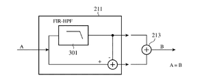
- the band division circuit 211 that constitutes the band division time correction signal processing circuit 21 includes an FIR digital filter.
- the FIR linear phase high bandpass filter 301 was used. Note that the audio system applied in the second embodiment has the same configuration as that of the first embodiment.
- the FIR (Finite Impulse Response) filter is a filter in which the duration of the impulse response is finite (the impulse response becomes 0 within the finite time), and the linear phase is the phase at all frequencies. It has a certain linear phase characteristic.
- the R channel input signal is extracted as a tweeter component only signal by the FIR linear phase high-pass filter 301, and then the tweeter component signal is subtracted from the R channel input signal to extract the woofer component signal.
- the signal is divided into a tweeter component signal and a woofer component signal.
- a delay process for adjusting the time axis by the delay circuit 212 is performed for each of the divided bands or one of them.
- the delay time T T for signals tweeter component if the delay time for signals woofer component and T W, signal T T T -T W is relatively tweeter component on the signal woofer component Will represent the time spent.
- the time axis shift of the speaker unit 5 is achieved by using the FIR linear phase high bandpass filter 301 formed of an FIR digital filter for the band dividing circuit 211 of the band dividing time correction signal processing circuit 21.
- an FIR digital filter having a linear phase characteristic is used for the band division time correction signal processing circuit 22 (band division circuit) similarly for the L channel input signal.
- the FIR linear phase high bandpass filter 301 formed of an FIR digital filter is used.
- the FIR linear phase low bandpass filter may be substituted, and in this case, the signal divided by the difference is a tweeter component. Become.
- the tweeter component signal extracted by the FIR linear phase high-pass filter 301 reflects the characteristics of the FIR filter having the linear phase characteristic, but the tweeter component signal is removed.
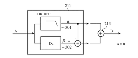
- the characteristics of the FIR filter described above are not reflected in the signal of the woofer component divided. Therefore, in the third embodiment described below, as shown in an example of the circuit configuration in FIG. 4, the band division time correction signal processing circuit 21 subtracts the tweeter component signal from the R channel input signal. And inserting a delay circuit 302 (second delay circuit) having a delay amount D2 corresponding to the group delay time of the FIR linear phase high-band pass filter 301 into the path ⁇ for extracting the signal of the woofer component divided by did.
- the group delay means a phenomenon in which the tone burst is outputted with a slight delay
- the group delay time means a frequency differential value of the phase shift
- the woofer component signal divided by subtracting the tweeter component signal from the input signal can also have good frequency characteristics with a flat pass band.
- Embodiment 4 FIG. According to the above-described third embodiment, either the woofer component signal or the tweeter component signal output from the band dividing circuit 211 further passes through the delay circuit 212 that performs time axis adjustment, and the mixing circuit 213. Is synthesized. At this time, depending on the delay amount of the delay circuit 212 for time axis adjustment, the value of the synthesis characteristic of the crossover frequency has a peak of 1.4 times at the maximum. For this reason, there is a possibility that the dynamic range is reduced in the digital filter constituting the band dividing circuit 211.
- the signal path of the tweeter component output by the band division circuit 211 constituting the band division time correction signal processing circuit 21 A phase correction circuit (PAC303) for correcting the phase of the crossover frequency is inserted into at least one of the signal paths ⁇ of the woofer component generated by the difference between ⁇ and the input signal.
- PAC303 phase correction circuit
- the tweeter component and woofer component signals output from the band dividing circuit 211 pass through the time axis adjustment delay circuit 212 (delay amount D1), and then either the tweeter component or the woofer component signal.
- both pass through a phase correction circuit (PAC 303) that rotates only the phase with a flat frequency characteristic.
- the tweeter component and woofer component signals that have passed through the phase correction circuit (PAC303) are combined by the mixing circuit 213, and the two-channel amplifier 3 amplifies the input signals of both the R and L channels, and then the crossover network circuit. 4 is output.
- Each speaker 5 is subjected to band division assigned to each speaker 5 by the crossover network circuit 4 and is driven based on an input signal for each of the divided channels.
- the tweeter component and woofer component signals that have passed through the phase correction circuit (PAC 303) are combined by the mixing circuit 213.
- the correction amount of the phase correction circuit 303 is optimized. By doing so, the dip generated at the crossover frequency can be suppressed. This makes it possible to correct the time axis between the speaker units 5 while ensuring high linearity.
- one amplifier circuit (two-channel amplifier 3) is arranged for each channel, and a crossover network is provided.
- the time axis between the speaker units 5 can be arbitrarily set, and high linearity and flat frequency characteristics are provided. This makes it possible to provide an audio system with good performance at low cost.
- the DSP 23 measures the rise time for each speaker unit 5 by searching for a peak value exceeding the threshold value from the impulse responses of the plurality of speaker units 5, for example.
- the difference calculation with the rise time of the speaker unit is performed, and the delay amount at the time of reproduction of each speaker unit 5 is set according to the result of the difference calculation.
- This is a well-known technique as time alignment means that adjusts so that the sound radiated from each speaker unit arrives at the listener's listening position simultaneously by applying a delay process to the signal supplied to each speaker unit 5.
- the above functions may be realized in cooperation with a CPU (not shown).
- the in-vehicle audio system has been exemplified.
- the present invention is not limited to the in-vehicle audio system but depends on the field such as home use as well as theater use. Without being applicable to all audio systems.
- the functions of the constituent blocks included in the band division time correction signal processing apparatus 2 shown in FIG. 1 may be all realized by software, or at least a part thereof may be realized by hardware.
- the impulse responses of a plurality of speaker units 5 whose playback bands are divided are observed, the inverse transfer function of each speaker unit 5 is obtained, the convolution operation is performed, and the distance between each speaker unit 5 and the listener's viewing position
- the data processing in the DSP 23 that determines the delay amount of the delay circuit 212 that adjusts the arrival time of the sound caused by the difference may be realized on a computer by one or a plurality of programs, and at least a part thereof is implemented by hardware. It may be realized.
- the embodiment of the present invention has been described with respect to the case where the frequency band is divided into two bands, that is, the low band component and the high band component. It is also possible to perform three or more band divisions by inserting a band division circuit having a configuration in multiple stages.
- the band division time correction signal processing apparatus extracts a high-band component or low-band component signal from an input signal and then extracts the high-band component or low-band component extracted from the input signal.
- a delay circuit that delays at least one of the signals of at least two band components for adjusting a sound arrival time
- a band division signal that includes at least a high band component or a low band component output by the delay circuit
- the band division A low-band component or a band-divided signal including at least a high-band component output by the circuit is synthesized and output to the amplifier.
- the linearity of the transfer characteristic at the listening position is improved, and the peak and dip at the time of mixing are improved. Since generation can be suppressed, it is suitable for use in an in-vehicle audio system including a band division time correction signal processing device.
Landscapes
- Physics & Mathematics (AREA)
- Engineering & Computer Science (AREA)
- Acoustics & Sound (AREA)
- Signal Processing (AREA)
- Health & Medical Sciences (AREA)
- General Health & Medical Sciences (AREA)
- Otolaryngology (AREA)
- Stereophonic System (AREA)
- Circuit For Audible Band Transducer (AREA)
- Tone Control, Compression And Expansion, Limiting Amplitude (AREA)
- Fittings On The Vehicle Exterior For Carrying Loads, And Devices For Holding Or Mounting Articles (AREA)
Abstract
Description
この場合、各信号に遅延処理を施すことにより4個のスピーカユニットから放射される音がリスナー位置で同時に到達するようなタイムアライメント処理(時間調整)がなされる。このように、各スピーカユニットとリスナーの視聴位置との間の距離差により生じる音場の偏りを、音の到達時間を調整することによって補正する帯域分割時間補正信号処理装置が知られている。
この場合、スピーカユニットの数だけ増幅器が必要となるため高コストとなり、また配線が複雑になり、多くのスペースを要する等の問題があった。
但しこの方式によれば、時間軸以外の周波数特性や位相特性も同時に補正してしまい、他の特性をそのままにして時間軸のみ単独に調整することはできない。また時間軸の値を独立に微調整することもできない。
しかしながら、帯域分割回路により失われる信号と、二重に加算される信号が発生し、これらにより再生音のリニアリティが劣化することに加え、ミキシング時に帯域分割周波数(クロスオーバ周波数)付近の周波数特性にピークやディップを生じる欠点があった。
実施の形態1.
図1は、この発明の実施の形態1に係る帯域分割時間補正信号処理装置を含むオーディオシステムの内部構成を示すブロック図である。
ここでは、R、L、2チャンネルのオーディオシステムが例示されており、このオーディオシステムは、入力ソースとなるプレーヤ1と、帯域分割時間補正信号処理装置2と、2チャンネル増幅器3と、クロスオーバーネットワーク回路4と、ウーファとツイータからなる2ウェイのスピーカユニット5と、により構成される。
帯域分割回路211は、プレーヤ1から出力されるRチャンネルの入力信号から、ツイータ成分(高帯域成分)とウーファ成分(低帯域成分)の信号を抽出して後段の遅延回路212へ出力する。帯域分割回路211は、入力信号から高帯域成分もしくは低帯域成分の信号を抽出後、Rチャンネルの入力信号から先に抽出された高帯域成分もしくは低帯域成分の信号を差し引いた、低帯域成分もしくは高帯域成分の信号を抽出する。
なお、ここでは、帯域分割回路211として引き算型高帯域通過フィルタ300を使用したが、引き算型低帯域通過フィルタで代替しても良く、この場合、プレーヤ1から出力されるRチャンネルの入力信号からウーファ成分の信号を抽出し、その後、Rチャンネル入力信号から、先に抽出されたウーファ成分の信号を差し引いたツイータ成分の信号を抽出することになる。
ミキシング回路213は、遅延回路212により出力されるウーファ成分の信号と、帯域分割回路211により出力されるツイータ成分の信号とを合成して2チャンネル増幅器3に出力する。
なお、Lチャンネルの帯域分割時間補正信号処理回路22は、プレーヤ1から出力されるLチャンネルの入力信号を取得する他は、上記したRチャンネルの帯域分割時間補正信号処理回路21と同様の回路構成を有するため、説明の重複を回避する意味で省略する。
クロスオーバーネットワーク回路4は、スピーカユニット5側の帯域分割器であり、Rチャンネル用ネットワーク41と、Lチャンネル用ネットワーク42により構成され、2チャンネル増幅器3を介して帯域分割時間補正信号処理回路21、22により出力されるRチャンネル信号、Lチャンネル信号のそれぞれを、スピーカユニット5のクロスオーバー周波数と同等のカットオフ周波数を有する低帯域通過フィルタ(LPF)と高帯域通過フィルタ(HPF)により帯域分割して、ウーファWRとツイータTR、ウーファWLとツイータTLから成るそれぞれのスピーカユニット5に出力する。
また、クロスオーバーネットワーク回路4で帯域分割される周波数とほぼ同一の周波数で帯域分割する帯域分割回路211に引き算型の高帯域通過フィルタ300(デジタルフィルタ)を用いることで、聴取位置での伝達特性のリニアリティを改善することができる。ちなみに、帯域分割回路211を、従来のように、HPFとLPFで構成した場合、伝達関数的には入力(A)=出力(B)とはならず、これに対して引き算型のデジタルフィルタ300を用いることで、入力(A)=出力(B)とする伝達特性のリニアリティを確保するものである。
上記した実施の形態1の帯域分割時間補正信号処理装置2によれば、リスナーの聴取位置での伝達特性のリニアリティを改善することはできるが、帯域分割時間補正信号処理回路21を構成する帯域分割回路211に使用する引き算型のデジタルフィルタ(引き算型高帯域通過フィルタ300)の特性によっては、差分により分割されたウーファ成分、もしくはツイータ成分の信号における周波数特性の平坦性が得られない。
このため、以下に説明する実施の形態2では、例えば、図3に回路構成の一例が示されるように、帯域分割時間補正信号処理回路21を構成する帯域分割回路211に、FIRデジタルフィルタから成るFIR直線位相高帯域通過フィルタ301を使用することとした。なお、実施の形態2で適用されるオーディオシステムは、上記した実施の形態1と同様の構成を有するものとする。
この場合、Rチャンネル入力信号は、FIR直線位相高帯域通過フィルタ301によりツイータ成分のみの信号が抽出され、その後、Rチャンネル入力信号からこのツイータ成分の信号を引き去ってウーファ成分の信号を抽出することにより、ツイータ成分とウーファ成分の信号に分割される。そして、この分割された帯域毎に、あるいはいずれか一方に遅延回路212による時間軸調整用の遅延処理を施す。ここで、ツイータ成分の信号に対する遅延時間をTT、ウーファ成分の信号に対する遅延時間をTWとすれば、TT-TWが相対的にツイータ成分の信号がウーファ成分の信号に対して遅延した時間を表すことになる。
上記した実施の形態2によれば、FIR直線位相高帯域通過フィルタ301により抽出されるツイータ成分の信号には直線位相特性を有するFIRフィルタの特徴が反映されるが、ツイータ成分の信号を引き去って分割されるウーファ成分の信号には上記したFIRフィルタの特徴が反映されない。
このため、以下に説明する実施の形態3では、図4にその回路構成の一例が示されるように、帯域分割時間補正信号処理回路21において、Rチャンネルの入力信号からツイータ成分の信号を引き去って分割されるウーファ成分の信号を抽出するパスβに、FIR直線位相高帯域通過フィルタ301の群遅延時間に相当する遅延量D2を有する遅延回路302(第2の遅延回路)を挿入することとした。
上記した実施の形態3によれば、帯域分割回路211により出力されるウーファ成分の信号と、ツイータ成分の信号のいずれかは、更に、時間軸調整を行う遅延回路212を通過し、ミキシング回路213で合成される。このとき、時間軸調整用の遅延回路212の遅延量によってはクロスオーバー周波数の合成特性の値が最大で1.4倍のピークを持つ。
このため、帯域分割回路211を構成するデジタルフィルタ内でダイナミックレンジの減少を引き起こす可能性がある。このとき、直線位相特性を有するFIRデジタルフィルタ(FIR直線位相高帯域通過フィルタ301)の採用により位相直線性が得られるため両信号の位相が完全に合致し、クロスオーバー周波数の合成特性の値が1倍を超えることはなく、したがって、帯域分割回路211内でダイナミックレンジが減少することはない。但し、両信号間でクロスオーバー周波数での位相ずれが発生した場合、ディップを発生する可能性がある。
また、図1に示す帯域分割時間補正信号処理装置2が有する各構成ブロックの機能は、全てをソフトウェアによって実現しても、あるいはその少なくとも一部をハードウェアで実現してもよい。例えば、再生帯域が分割された複数のスピーカユニット5のインパルス応答を観測し、各スピーカユニット5の逆伝達関数を求めて畳み込み演算を行い、各スピーカユニット5とリスナーの視聴位置との間の距離差によって生じる音の到達時間を調整する遅延回路212の遅延量を決定するDSP23におけるデータ処理は、1または複数のプログラムによりコンピュータ上で実現してもよく、また、その少なくとも一部をハードウェアで実現してもよい。
また、上記では発明の実施の形態について、低帯域成分と高帯域成分の2つの帯域に分割を行う場合について説明したが、帯域分割回路211とミキシング回路213の間に、異なる分割周波数の同様な構成の帯域分割回路を多段に挿入することで、3つ以上の帯域分割を行うことも可能である。
Claims (5)
- 再生帯域が分割された複数のスピーカユニットを、チャンネル毎にクロスオーバーネットワーク回路を介して1個の増幅器で駆動するオーディオシステムにおいて、
入力信号から高帯域成分もしくは低帯域成分の信号を抽出後、前記入力信号から前記抽出された高帯域成分もしくは低帯域成分の信号を差し引いた、低帯域成分もしくは高帯域成分の信号を抽出するチャンネル毎に、少なくとも1つの帯域分割回路と、
前記少なくとも1組の帯域分割回路により出力される高帯域成分、および低帯域成分を含む少なくとも2種類の帯域成分の信号の少なくとも一方を音の到達時間調整用に遅延させる遅延回路と、
前記遅延回路により出力される高帯域成分もしくは低帯域成分を少なくとも含む帯域分割信号と、前記帯域分割回路により出力される低帯域成分もしくは高帯域成分を少なくとも含む帯域分割信号とを合成して前記増幅器に出力するミキシング回路と、
を備えたことを特徴とする帯域分割時間補正信号処理装置。 - 前記帯域分割回路は、
直線位相特性を有するFIRフィルタで構成されることを特徴とする請求項1記載の帯域分割時間補正信号処理装置。 - 前記FIRフィルタで構成される帯域分割回路は、
前記入力信号から、前記抽出された高帯域成分もしくは低帯域成分の信号を差し引いて低帯域成分もしくは高帯域成分の信号を抽出するパスに、自身の群遅延時間に相当する遅延量を有する第2の遅延回路を挿入して成ることを特徴とする請求項1記載の帯域分割時間補正信号処理装置。 - 前記遅延回路により出力される高帯域成分もしくは低帯域成分の信号が伝播するパス、もしくは前記帯域分割回路により出力される低帯域成分もしくは高帯域成分の信号が伝播するパスの少なくとも一方に、前記高帯域成分と低帯域成分のクロスオーバー周波数での位相を補正する位相補正回路を挿入して成ることを特徴とする請求項1記載の帯域分割時間補正信号処理装置。
- 前記再生帯域が分割された複数のスピーカユニットのインパルス応答を観測し、前記各スピーカユニットの逆伝達関数を求めて畳み込み演算を行い、前記各スピーカユニットと視聴位置との間の距離差によって生じる音の到達時間を調整する前記遅延回路の遅延量を決定するデジタル信号処理回路と、
を備えたことを特徴とする請求項1記載の帯域分割時間補正信号処理装置。
Priority Applications (4)
| Application Number | Priority Date | Filing Date | Title |
|---|---|---|---|
| US12/744,238 US8358790B2 (en) | 2008-01-31 | 2008-11-18 | Band-splitting time compensation signal processing device |
| JP2009551325A JP4975112B2 (ja) | 2008-01-31 | 2008-11-18 | 帯域分割時間補正信号処理装置 |
| CN200880126084.6A CN101926182B (zh) | 2008-01-31 | 2008-11-18 | 频带分割时间校正信号处理装置 |
| DE112008003305.6T DE112008003305B4 (de) | 2008-01-31 | 2008-11-18 | Bandaufteilungs-Zeitausgleich-Signalverarbeitungs-Vorrichtung |
Applications Claiming Priority (2)
| Application Number | Priority Date | Filing Date | Title |
|---|---|---|---|
| JP2008-021218 | 2008-01-31 | ||
| JP2008021218 | 2008-01-31 |
Publications (1)
| Publication Number | Publication Date |
|---|---|
| WO2009095965A1 true WO2009095965A1 (ja) | 2009-08-06 |
Family
ID=40912336
Family Applications (1)
| Application Number | Title | Priority Date | Filing Date |
|---|---|---|---|
| PCT/JP2008/003360 Ceased WO2009095965A1 (ja) | 2008-01-31 | 2008-11-18 | 帯域分割時間補正信号処理装置 |
Country Status (5)
| Country | Link |
|---|---|
| US (1) | US8358790B2 (ja) |
| JP (1) | JP4975112B2 (ja) |
| CN (1) | CN101926182B (ja) |
| DE (1) | DE112008003305B4 (ja) |
| WO (1) | WO2009095965A1 (ja) |
Cited By (7)
| Publication number | Priority date | Publication date | Assignee | Title |
|---|---|---|---|---|
| JP2014053684A (ja) * | 2012-09-05 | 2014-03-20 | Jvc Kenwood Corp | 音声再生装置、調整方法及びプログラム |
| WO2014208431A1 (ja) | 2013-06-27 | 2014-12-31 | クラリオン株式会社 | 伝搬遅延補正装置及び伝搬遅延補正方法 |
| WO2015050006A1 (ja) * | 2013-10-01 | 2015-04-09 | クラリオン株式会社 | 音場測定装置、音場測定方法および音場測定プログラム |
| US10362396B2 (en) | 2015-02-19 | 2019-07-23 | Clarion Co., Ltd. | Phase control signal generation device, phase control signal generation method, and phase control signal generation program |
| JP2020043597A (ja) * | 2014-06-03 | 2020-03-19 | ドルビー ラボラトリーズ ライセンシング コーポレイション | 反射音レンダリングのために上方発射ドライバをもつオーディオ・スピーカー |
| JP2020512771A (ja) * | 2017-03-30 | 2020-04-23 | マジック リープ, インコーポレイテッドMagic Leap,Inc. | 非遮断型デュアルドライバイヤホン |
| JPWO2019003418A1 (ja) * | 2017-06-30 | 2020-04-23 | ソフトバンク株式会社 | 音情報処理装置、音情報処理方法、およびプログラム |
Families Citing this family (16)
| Publication number | Priority date | Publication date | Assignee | Title |
|---|---|---|---|---|
| WO2009144781A1 (ja) * | 2008-05-27 | 2009-12-03 | パイオニア株式会社 | 音声再生装置 |
| CA2731045C (en) * | 2010-02-05 | 2015-12-29 | Qnx Software Systems Co. | Enhanced spatialization system |
| JP2012227589A (ja) * | 2011-04-15 | 2012-11-15 | Clarion Co Ltd | デジタルスピーカーシステム |
| JP6051505B2 (ja) * | 2011-10-07 | 2016-12-27 | ソニー株式会社 | 音声処理装置および音声処理方法、記録媒体、並びにプログラム |
| US9307323B2 (en) * | 2011-11-22 | 2016-04-05 | Actiwave Ab | System and method for bass enhancement |
| JP2014168228A (ja) * | 2013-01-30 | 2014-09-11 | Yamaha Corp | 放音装置 |
| FR3021470A1 (fr) * | 2014-05-26 | 2015-11-27 | Pierre Jacques Jean Bozzi | Dispositif de separation de voies pour transmission fidele d'un signal a travers un systeme a multiples canaux en frequence |
| CN114694632B (zh) * | 2015-09-16 | 2025-08-19 | 株式会社东芝 | 语音处理装置 |
| KR102468272B1 (ko) * | 2016-06-30 | 2022-11-18 | 삼성전자주식회사 | 음향 출력 장치 및 그 제어 방법 |
| EP3485655B1 (en) * | 2016-07-15 | 2024-01-03 | Sonos Inc. | Spectral correction using spatial calibration |
| US10499153B1 (en) * | 2017-11-29 | 2019-12-03 | Boomcloud 360, Inc. | Enhanced virtual stereo reproduction for unmatched transaural loudspeaker systems |
| EP3742762B1 (en) * | 2018-01-19 | 2022-10-26 | JVCKenwood Corporation | Reproducing device, reproducing method, and in-vehicle loudspeaker system |
| JP7247582B2 (ja) * | 2018-12-28 | 2023-03-29 | ヤマハ株式会社 | オーディオ信号制御回路、および、オーディオ信号制御方法 |
| CN110068730B (zh) * | 2019-05-07 | 2020-08-07 | 中国科学院电子学研究所 | 双频段频谱数据采集方法及装置 |
| CN112584298B (zh) * | 2019-09-27 | 2022-08-02 | 宏碁股份有限公司 | 信号测量的校正系统及其校正方法 |
| KR102475665B1 (ko) * | 2020-11-12 | 2022-12-07 | 엑스멤스 랩스 인코포레이티드 | 크로스오버 회로 |
Citations (6)
| Publication number | Priority date | Publication date | Assignee | Title |
|---|---|---|---|---|
| JPS61135298A (ja) * | 1984-12-06 | 1986-06-23 | Matsushita Electric Ind Co Ltd | スピ−カ用音質調整装置 |
| JPS6297497A (ja) * | 1985-10-23 | 1987-05-06 | Matsushita Electric Ind Co Ltd | 音質調整装置 |
| JPS6342599A (ja) * | 1986-08-08 | 1988-02-23 | Yamaha Corp | スピ−カ再生装置 |
| JPH07212896A (ja) * | 1994-01-17 | 1995-08-11 | Mitsubishi Electric Corp | 音響再生装置 |
| JP2001119800A (ja) * | 1999-10-19 | 2001-04-27 | Matsushita Electric Ind Co Ltd | 車載用音像制御装置 |
| JP2005223887A (ja) * | 2004-01-06 | 2005-08-18 | Pioneer Electronic Corp | 音響特性調整装置 |
Family Cites Families (12)
| Publication number | Priority date | Publication date | Assignee | Title |
|---|---|---|---|---|
| US4137510A (en) * | 1976-01-22 | 1979-01-30 | Victor Company Of Japan, Ltd. | Frequency band dividing filter |
| US4243840A (en) * | 1978-12-22 | 1981-01-06 | Teledyne Industries, Inc. | Loudspeaker system |
| JPS6442599A (en) * | 1987-08-11 | 1989-02-14 | Shinko Electric Ind Co | Plating barrel |
| JP3148060B2 (ja) * | 1993-12-02 | 2001-03-19 | 富士通テン株式会社 | 聴取位置自動補正装置 |
| US5930374A (en) | 1996-10-17 | 1999-07-27 | Aphex Systems, Ltd. | Phase coherent crossover |
| KR0185021B1 (ko) * | 1996-11-20 | 1999-04-15 | 한국전기통신공사 | 다채널 음향시스템의 자동 조절장치 및 그 방법 |
| JP3381219B2 (ja) * | 1999-06-09 | 2003-02-24 | 日本マランツ株式会社 | ステレオ信号処理装置 |
| JP3821228B2 (ja) * | 2002-11-15 | 2006-09-13 | ソニー株式会社 | オーディオ信号の処理方法および処理装置 |
| JP2004201109A (ja) * | 2002-12-19 | 2004-07-15 | Fujitsu Ten Ltd | 帯域フィルタ |
| BRPI0406679A (pt) * | 2003-01-09 | 2005-12-20 | Boston Acoustics Inc | Cruzamento de alto falante de áudio possuindo dois ou mais alojamentos de filtro |
| EP1994795B1 (en) * | 2006-03-15 | 2010-07-21 | Dolby Laboratories Licensing Corporation | Stereophonic sound imaging |
| JP4785650B2 (ja) * | 2006-06-30 | 2011-10-05 | キヤノン株式会社 | 音声信号処理装置および音声信号処理方法 |
-
2008
- 2008-11-18 WO PCT/JP2008/003360 patent/WO2009095965A1/ja not_active Ceased
- 2008-11-18 CN CN200880126084.6A patent/CN101926182B/zh active Active
- 2008-11-18 DE DE112008003305.6T patent/DE112008003305B4/de active Active
- 2008-11-18 JP JP2009551325A patent/JP4975112B2/ja active Active
- 2008-11-18 US US12/744,238 patent/US8358790B2/en active Active
Patent Citations (6)
| Publication number | Priority date | Publication date | Assignee | Title |
|---|---|---|---|---|
| JPS61135298A (ja) * | 1984-12-06 | 1986-06-23 | Matsushita Electric Ind Co Ltd | スピ−カ用音質調整装置 |
| JPS6297497A (ja) * | 1985-10-23 | 1987-05-06 | Matsushita Electric Ind Co Ltd | 音質調整装置 |
| JPS6342599A (ja) * | 1986-08-08 | 1988-02-23 | Yamaha Corp | スピ−カ再生装置 |
| JPH07212896A (ja) * | 1994-01-17 | 1995-08-11 | Mitsubishi Electric Corp | 音響再生装置 |
| JP2001119800A (ja) * | 1999-10-19 | 2001-04-27 | Matsushita Electric Ind Co Ltd | 車載用音像制御装置 |
| JP2005223887A (ja) * | 2004-01-06 | 2005-08-18 | Pioneer Electronic Corp | 音響特性調整装置 |
Cited By (13)
| Publication number | Priority date | Publication date | Assignee | Title |
|---|---|---|---|---|
| JP2014053684A (ja) * | 2012-09-05 | 2014-03-20 | Jvc Kenwood Corp | 音声再生装置、調整方法及びプログラム |
| WO2014208431A1 (ja) | 2013-06-27 | 2014-12-31 | クラリオン株式会社 | 伝搬遅延補正装置及び伝搬遅延補正方法 |
| US10375500B2 (en) | 2013-06-27 | 2019-08-06 | Clarion Co., Ltd. | Propagation delay correction apparatus and propagation delay correction method |
| JP2015070589A (ja) * | 2013-10-01 | 2015-04-13 | クラリオン株式会社 | 音場測定装置、音場測定方法および音場測定プログラム |
| US9883303B2 (en) | 2013-10-01 | 2018-01-30 | Clarion Co., Ltd. | Sound field measuring device, method and program |
| WO2015050006A1 (ja) * | 2013-10-01 | 2015-04-09 | クラリオン株式会社 | 音場測定装置、音場測定方法および音場測定プログラム |
| JP2020043597A (ja) * | 2014-06-03 | 2020-03-19 | ドルビー ラボラトリーズ ライセンシング コーポレイション | 反射音レンダリングのために上方発射ドライバをもつオーディオ・スピーカー |
| JP7073324B2 (ja) | 2014-06-03 | 2022-05-23 | ドルビー ラボラトリーズ ライセンシング コーポレイション | 反射音レンダリングのために上方発射ドライバをもつオーディオ・スピーカー |
| US10362396B2 (en) | 2015-02-19 | 2019-07-23 | Clarion Co., Ltd. | Phase control signal generation device, phase control signal generation method, and phase control signal generation program |
| JP2020512771A (ja) * | 2017-03-30 | 2020-04-23 | マジック リープ, インコーポレイテッドMagic Leap,Inc. | 非遮断型デュアルドライバイヤホン |
| US11722812B2 (en) | 2017-03-30 | 2023-08-08 | Magic Leap, Inc. | Non-blocking dual driver earphones |
| US12133043B2 (en) | 2017-03-30 | 2024-10-29 | Magic Leap, Inc. | Non-blocking dual driver earphones |
| JPWO2019003418A1 (ja) * | 2017-06-30 | 2020-04-23 | ソフトバンク株式会社 | 音情報処理装置、音情報処理方法、およびプログラム |
Also Published As
| Publication number | Publication date |
|---|---|
| JPWO2009095965A1 (ja) | 2011-05-26 |
| CN101926182A (zh) | 2010-12-22 |
| US20100260356A1 (en) | 2010-10-14 |
| US8358790B2 (en) | 2013-01-22 |
| DE112008003305B4 (de) | 2015-02-19 |
| DE112008003305T5 (de) | 2010-11-25 |
| CN101926182B (zh) | 2013-08-21 |
| JP4975112B2 (ja) | 2012-07-11 |
Similar Documents
| Publication | Publication Date | Title |
|---|---|---|
| JP4975112B2 (ja) | 帯域分割時間補正信号処理装置 | |
| US8477951B2 (en) | Front surround system and method of reproducing sound using psychoacoustic models | |
| KR102346935B1 (ko) | 매칭되지 않은 트랜스오럴 라우드스피커 시스템용 강화된 가상 스테레오 재생 | |
| KR0137182B1 (ko) | 서라운드 신호 처리 장치 | |
| JP7410082B2 (ja) | クロストークプロセッシングb-チェーン | |
| US8605914B2 (en) | Nonlinear filter for separation of center sounds in stereophonic audio | |
| Bouéri et al. | Audio signal decorrelation based on a critical band approach | |
| US20080101631A1 (en) | Front surround sound reproduction system using beam forming speaker array and surround sound reproduction method thereof | |
| JP4979837B2 (ja) | 多重オーディオチャンネル群の再現の向上 | |
| US9913036B2 (en) | Apparatus and method and computer program for generating a stereo output signal for providing additional output channels | |
| CN102611966A (zh) | 用于虚拟环绕渲染的扬声器阵列 | |
| US20240373184A1 (en) | A method of processing audio for playback of immersive audio | |
| JP3925633B2 (ja) | 音声再生装置 | |
| JPH0530600A (ja) | 音像制御装置 | |
| JP2008028640A (ja) | オーディオ再生装置 | |
| KR20090086751A (ko) | 오디오 신호의 처리 장치 및 이의 처리 방법 | |
| KR20060083264A (ko) | 음원의 3차원 효과 증대 장치 | |
| JP2008306357A (ja) | 音像定位処理装置 | |
| HK1196198B (en) | Apparatus and method and computer program for generating a stereo output signal for providing additional output channels |
Legal Events
| Date | Code | Title | Description |
|---|---|---|---|
| WWE | Wipo information: entry into national phase |
Ref document number: 200880126084.6 Country of ref document: CN |
|
| 121 | Ep: the epo has been informed by wipo that ep was designated in this application |
Ref document number: 08871679 Country of ref document: EP Kind code of ref document: A1 |
|
| ENP | Entry into the national phase |
Ref document number: 2009551325 Country of ref document: JP Kind code of ref document: A |
|
| WWE | Wipo information: entry into national phase |
Ref document number: 12744238 Country of ref document: US |
|
| WWE | Wipo information: entry into national phase |
Ref document number: 1120080033056 Country of ref document: DE |
|
| RET | De translation (de og part 6b) |
Ref document number: 112008003305 Country of ref document: DE Date of ref document: 20101125 Kind code of ref document: P |
|
| 122 | Ep: pct application non-entry in european phase |
Ref document number: 08871679 Country of ref document: EP Kind code of ref document: A1 |