WO2009093701A1 - 圧縮機 - Google Patents
圧縮機 Download PDFInfo
- Publication number
- WO2009093701A1 WO2009093701A1 PCT/JP2009/051096 JP2009051096W WO2009093701A1 WO 2009093701 A1 WO2009093701 A1 WO 2009093701A1 JP 2009051096 W JP2009051096 W JP 2009051096W WO 2009093701 A1 WO2009093701 A1 WO 2009093701A1
- Authority
- WO
- WIPO (PCT)
- Prior art keywords
- cylinder
- piston
- pressure chamber
- chamber
- cylinder chamber
- Prior art date
- Legal status (The legal status is an assumption and is not a legal conclusion. Google has not performed a legal analysis and makes no representation as to the accuracy of the status listed.)
- Ceased
Links
Images




Classifications
-
- F—MECHANICAL ENGINEERING; LIGHTING; HEATING; WEAPONS; BLASTING
- F04—POSITIVE - DISPLACEMENT MACHINES FOR LIQUIDS; PUMPS FOR LIQUIDS OR ELASTIC FLUIDS
- F04C—ROTARY-PISTON, OR OSCILLATING-PISTON, POSITIVE-DISPLACEMENT MACHINES FOR LIQUIDS; ROTARY-PISTON, OR OSCILLATING-PISTON, POSITIVE-DISPLACEMENT PUMPS
- F04C18/00—Rotary-piston pumps specially adapted for elastic fluids
- F04C18/30—Rotary-piston pumps specially adapted for elastic fluids having the characteristics covered by two or more of groups F04C18/02, F04C18/08, F04C18/22, F04C18/24, F04C18/48, or having the characteristics covered by one of these groups together with some other type of movement between co-operating members
- F04C18/32—Rotary-piston pumps specially adapted for elastic fluids having the characteristics covered by two or more of groups F04C18/02, F04C18/08, F04C18/22, F04C18/24, F04C18/48, or having the characteristics covered by one of these groups together with some other type of movement between co-operating members having both the movement defined in group F04C18/02 and relative reciprocation between the co-operating members
- F04C18/322—Rotary-piston pumps specially adapted for elastic fluids having the characteristics covered by two or more of groups F04C18/02, F04C18/08, F04C18/22, F04C18/24, F04C18/48, or having the characteristics covered by one of these groups together with some other type of movement between co-operating members having both the movement defined in group F04C18/02 and relative reciprocation between the co-operating members with vanes hinged to the outer member and reciprocating with respect to the outer member
-
- F—MECHANICAL ENGINEERING; LIGHTING; HEATING; WEAPONS; BLASTING
- F04—POSITIVE - DISPLACEMENT MACHINES FOR LIQUIDS; PUMPS FOR LIQUIDS OR ELASTIC FLUIDS
- F04C—ROTARY-PISTON, OR OSCILLATING-PISTON, POSITIVE-DISPLACEMENT MACHINES FOR LIQUIDS; ROTARY-PISTON, OR OSCILLATING-PISTON, POSITIVE-DISPLACEMENT PUMPS
- F04C23/00—Combinations of two or more pumps, each being of rotary-piston or oscillating-piston type, specially adapted for elastic fluids; Pumping installations specially adapted for elastic fluids; Multi-stage pumps specially adapted for elastic fluids
- F04C23/008—Hermetic pumps
-
- F—MECHANICAL ENGINEERING; LIGHTING; HEATING; WEAPONS; BLASTING
- F04—POSITIVE - DISPLACEMENT MACHINES FOR LIQUIDS; PUMPS FOR LIQUIDS OR ELASTIC FLUIDS
- F04C—ROTARY-PISTON, OR OSCILLATING-PISTON, POSITIVE-DISPLACEMENT MACHINES FOR LIQUIDS; ROTARY-PISTON, OR OSCILLATING-PISTON, POSITIVE-DISPLACEMENT PUMPS
- F04C29/00—Component parts, details or accessories of pumps or pumping installations, not provided for in groups F04C18/00 - F04C28/00
- F04C29/02—Lubrication; Lubricant separation
- F04C29/028—Means for improving or restricting lubricant flow
-
- F—MECHANICAL ENGINEERING; LIGHTING; HEATING; WEAPONS; BLASTING
- F04—POSITIVE - DISPLACEMENT MACHINES FOR LIQUIDS; PUMPS FOR LIQUIDS OR ELASTIC FLUIDS
- F04C—ROTARY-PISTON, OR OSCILLATING-PISTON, POSITIVE-DISPLACEMENT MACHINES FOR LIQUIDS; ROTARY-PISTON, OR OSCILLATING-PISTON, POSITIVE-DISPLACEMENT PUMPS
- F04C2210/00—Fluid
- F04C2210/26—Refrigerants with particular properties, e.g. HFC-134a
-
- F—MECHANICAL ENGINEERING; LIGHTING; HEATING; WEAPONS; BLASTING
- F04—POSITIVE - DISPLACEMENT MACHINES FOR LIQUIDS; PUMPS FOR LIQUIDS OR ELASTIC FLUIDS
- F04C—ROTARY-PISTON, OR OSCILLATING-PISTON, POSITIVE-DISPLACEMENT MACHINES FOR LIQUIDS; ROTARY-PISTON, OR OSCILLATING-PISTON, POSITIVE-DISPLACEMENT PUMPS
- F04C2210/00—Fluid
- F04C2210/26—Refrigerants with particular properties, e.g. HFC-134a
- F04C2210/263—HFO1234YF
Definitions
- the present invention relates to a compressor that compresses a refrigerant.
- a piston in which a roller and a blade are integrally formed is arranged inside a cylinder chamber formed inside the cylinder, and the piston makes the cylinder chamber a suction chamber (low-pressure chamber). Chamber) and discharge chamber (high pressure chamber). Then, the roller moves along the side wall surface while contacting the side wall surface of the cylinder chamber, whereby the volume of the discharge chamber changes and the refrigerant in the discharge chamber is compressed.
- the piston in order to prevent the movement of the piston from being obstructed by contact with the upper and lower wall surfaces of the cylinder chamber, the piston (roller and blade) is more than the cylinder chamber.
- the height is low. Since the roller is lower than the cylinder chamber, the lubricating oil flowing inside the roller flows into the low-pressure chamber through the gap between the roller and the upper and lower wall surfaces of the cylinder chamber.
- the amount of lubricating oil flowing into the low pressure chamber from the inside of the roller increases, the temperature of the refrigerant in the low pressure chamber increases due to this lubricating oil, and the performance of the compressor decreases.
- the lubricating oil flows from the high pressure chamber to the low pressure chamber through a gap between the blade and the upper and lower wall surfaces of the cylinder chamber.
- the temperature of the high-pressure chamber is high, and the temperature of the lubricating oil in the high-pressure chamber is also high. Therefore, when the amount of lubricating oil flowing from the high pressure chamber into the low pressure chamber increases, the temperature of the refrigerant in the low pressure chamber increases, and the performance of the compressor decreases.
- An object of the present invention is to provide a compressor in which the amount of the lubricating oil flowing into the low pressure chamber is small and the performance is not deteriorated.
- a compressor according to a first aspect of the present invention is disposed in a sealed space, is provided with a cylinder provided with a cylinder chamber therein, and is disposed within the cylinder chamber, the outer peripheral surface of which is the side of the cylinder chamber.
- a refrigerant is introduced from the outside, which moves along the side wall surface so as to abut against the wall surface, compresses the refrigerant in the cylinder chamber, and discharges the compressed refrigerant to the sealed space.
- An annular roller that is divided into a low-pressure chamber and changes the volume of the high-pressure chamber and the low-pressure chamber, and is disposed inside the cylinder chamber.
- the cylinder chamber together with the roller is divided into the high-pressure chamber and the low-pressure chamber.
- the roller is constituted by a plurality of roller constituent members stacked in the axial direction of the cylinder.
- the roller is constituted by a plurality of roller constituent members stacked in the axial direction of the cylinder, an oil film of lubricating oil is formed between the roller constituent members during driving of the compressor, and the roller configuration A gap is formed between the members, and the size of the gap between the roller constituent member and the wall surfaces on both sides of the cylinder chamber in the axial direction of the cylinder and the size of the gap between the roller constituent members are the same as in the past.
- the roller is made of one member, the size of the gap between the roller and the wall surfaces on both sides of the cylinder chamber in the axial direction of the cylinder is smaller.
- the amount of liquid flowing in the gap is smaller as the number of gaps is larger and the size of one gap is smaller when the total gap size is the same. .
- the sum of the size of the gap between the roller constituent member and the wall surfaces on both sides of the cylinder chamber in the cylinder chamber and the size of the gap between the roller constituent members is one member as in the prior art. Even if it is the same as the sum of the sizes of the gaps between the rollers and the wall surfaces on both sides of the cylinder chamber in the axial direction in the cylinder chamber, the amount of lubricating oil flowing into the low pressure chamber can be reduced.
- the size of the gap between the roller constituent member and the wall surfaces on both sides of the cylinder chamber in the axial direction of the cylinder, and the roller constituent member is larger than the total size of the gaps between the rollers and the wall surfaces on both sides of the cylinder chamber in the axial direction of the cylinder when the rollers are configured by one member as in the prior art. It is possible to reliably prevent the roller constituent members from coming into contact with the wall surfaces on both sides of the cylinder chamber in the axial direction of the cylinder.
- the distance between the roller constituent member and the wall surfaces on both sides of the cylinder chamber in the axial direction of the cylinder is shortened by an amount corresponding to the gap between the roller constituent member.
- a compressor according to a second aspect of the invention is the compressor according to the first aspect of the invention, wherein the blade is constituted by a plurality of blade constituent members stacked in the axial direction of the cylinder.
- the blade is constituted by a plurality of laminated blade constituent members, an oil film of lubricating oil is formed between the blade constituent members and a gap is formed between the blade constituent members.
- the size of the gap between the wall surfaces on both sides in the axial direction of the cylinder and the size of the gap between the blade constituent members are the same as in the conventional case where the blade is configured by one member. This is smaller than the size of the gap between the blade and the wall surfaces on both sides of the cylinder chamber in the axial direction of the cylinder.
- the sum of the size of the gap between the blade constituent member and the wall surfaces on both sides of the cylinder chamber in the cylinder chamber and the size of the gap between the blade constituent members is one member as in the prior art.
- the amount of lubricating oil flowing from the high-pressure chamber to the low-pressure chamber can be reduced even if it is the same as the sum of the sizes of the gaps between the blades and the wall surfaces on both sides of the cylinder chamber in the axial direction in the cylinder chamber. .
- the size of the gap between the blade constituent member and the upper and lower wall surfaces of the cylinder chamber, and the gap between the blade constituent members can be made larger than the sum of the sizes of the gaps between the blade and the wall surfaces on both sides of the cylinder chamber in the axial direction of the cylinder when the blade is constituted by one member as in the prior art, It is possible to reliably prevent the blade constituent member from coming into contact with the wall surfaces on both sides of the cylinder chamber in the axial direction of the cylinder.
- the blade when the blade is constituted by a single member, there is a risk that heat will be trapped in the central portion in the height direction of the blade and seizure may occur. Since the blades are formed by laminating the constituent members, the lubricating oil flows through the gaps between the blade constituent members, and the above-described seizure hardly occurs.
- the distance between the blade constituent member and the wall surfaces on both sides in the axial direction of the cylinder in the cylinder chamber is shortened by an amount corresponding to the gap between the blade constituent members.
- a compressor according to a third aspect of the present invention is disposed in a sealed space, and is disposed within a cylinder chamber provided with a cylinder chamber therein and inside the cylinder chamber, the outer peripheral surface of which is on the side of the cylinder chamber.
- a refrigerant is introduced from the outside, which moves along the side wall surface so as to abut against the wall surface, compresses the refrigerant in the cylinder chamber, and discharges the compressed refrigerant to the sealed space.
- An annular roller that is divided into a low-pressure chamber and changes the volume of the high-pressure chamber and the low-pressure chamber, and is disposed inside the cylinder chamber.
- the cylinder chamber together with the roller is divided into the high-pressure chamber and the low-pressure chamber.
- the blade is constituted by a plurality of blade constituent members stacked in the axial direction of the cylinder.
- This compressor can obtain the same effect as the compressor according to the second invention.
- a compressor according to a fourth aspect of the present invention is disposed in a sealed space, and includes a cylinder in which a cylinder chamber is provided, and a piston disposed in the cylinder chamber.
- a high-pressure chamber that moves along the side wall surface so that its outer peripheral surface abuts on the side wall surface of the cylinder chamber, and that compresses the refrigerant and discharges the compressed refrigerant to the sealed space.
- an annular roller that changes the volume of the high pressure chamber and the low pressure chamber, and is integrally formed with the roller, and is divided into the cylinder together with the roller.
- a blade that divides the chamber into the high-pressure chamber and the low-pressure chamber, and is configured by a plurality of piston constituent members stacked in the axial direction of the cylinder. It is characterized.
- the piston in which the roller and the blade are integrally formed is constituted by a plurality of piston constituent members stacked in the axial direction of the cylinder, the compressor according to the first to third inventions Since the roller and the blade are integrally formed, it is possible to prevent both from sliding and causing seizure.
- the size of the gap between the roller constituent member and the wall surfaces on both sides of the cylinder chamber in the axial direction of the cylinder and the total size of the gap between the roller constituent members can be reduced even if it is the same as the sum of the sizes of the gaps between the roller and the wall surfaces on both sides of the cylinder chamber in the axial direction of the cylinder when it can.
- the size of the gap between the roller constituent member and the wall surfaces on both sides of the cylinder chamber in the axial direction of the cylinder when the roller is constituted by one member as in the prior art. It can be made larger than the total, and it is possible to reliably prevent the roller constituent members from contacting the wall surfaces on both sides of the cylinder chamber in the axial direction of the cylinder.
- the total size of the gap between the blade constituent member and the wall surfaces on both sides of the cylinder chamber in the cylinder chamber in the axial direction of the cylinder and the size of the gap between the blade constituent members is The amount of lubricating oil flowing from the high-pressure chamber to the low-pressure chamber is reduced even if it is the same as the total size of the gap between the blade and the wall surfaces on both sides of the cylinder chamber in the axial direction in the cylinder chamber can do.
- the gap between the blade constituent member and the wall surfaces on both sides of the cylinder chamber in the axial direction of the cylinder are the gaps between the blades and the wall surfaces on both sides of the cylinder chamber in the axial direction of the cylinder when the blade is constituted by one member as in the prior art. It can be made larger than the total size, and it is possible to reliably prevent the blade constituent member from coming into contact with the wall surfaces on both sides of the cylinder chamber in the axial direction of the cylinder.
- the blade when the blade is constituted by a single member, there is a risk that heat will be trapped in the central portion in the height direction of the blade and seizure may occur. Since the blades are formed by laminating the blade constituent members, the lubricating oil flows in the gaps between the blade constituent members, and the above-described seizure hardly occurs.
- the piston in which the roller and the blade are integrally formed is constituted by a plurality of piston constituent members stacked in the axial direction of the cylinder, the same as in the first to third inventions.
- the effect can be obtained and the roller and the blade are integrally formed, so that it is possible to prevent both from sliding and causing seizure.
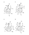
- FIG. 2 It is a schematic block diagram of the compressor which concerns on embodiment in this invention. It is a top view which shows the structure and operation
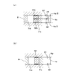
- 4A and 4B are cross-sectional views taken along the line IV-IV in FIG. 2, in which FIG. 2A shows the embodiment, and FIG. FIG. 5 is a cross-sectional view taken along the line VV of FIG. 2, in which (a) shows the embodiment and (b) shows the conventional one.
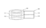
- FIG. 10 is a diagram corresponding to FIG.
- FIG. 10 is a diagram corresponding to FIG.
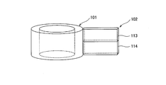
- FIG. 10 is a diagram corresponding to FIG.
- FIG. 10 is a diagram corresponding to FIG.
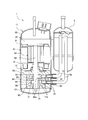
- FIG. 1 is a schematic configuration diagram of a compressor according to the present embodiment.
- the compressor 1 is, for example, a compressor used in an air conditioner such as an air conditioner.
- the compressor 1 compresses the refrigerant from which moisture has been removed and is introduced from the accumulator 2, and is discharged from a discharge passage 25 disposed at the upper end portion thereof. Discharge the compressed refrigerant.
- the compressor 1 includes a casing 11, a motor 12, and a compression mechanism 13.
- the casing 11 includes a body 21, a top 22, and a bottom 23.
- drum 21 is a substantially cylindrical member extended in the up-down direction, The upper and lower ends are opening.
- two connection ports 24 are formed on the side surface of the body 21 along the vertical direction to which the discharge pipe 2a for discharging the refrigerant of the accumulator 2 is connected at the lower right end.
- the top 22 is a member that closes the opening at the upper end of the body 21.
- the top 22 is provided with the discharge channel 25 described above.
- the bottom 23 is a member that closes the opening at the lower end of the body 21.
- a sealed space 26 surrounded by the body 21, the top 22, and the bottom 23 is formed.
- the motor 12 is disposed in the sealed space 26 and has a stator 31 and a rotor 32.
- the stator 31 is fixed to the inner wall surface of the body 21.
- the rotor 32 is disposed on the radially inner side of the stator 31, and an upper end portion of a shaft 60 extending in the vertical direction is fixed to a substantially central portion thereof.
- the rotor rotates together with the shaft 60 by the magnetic force generated between the stator 31 and the rotor 32.
- the configuration of the stator 31 and the rotor 32 is the same as that of a conventional motor, and thus detailed description thereof is omitted here.
- the compression mechanism 13 is disposed in the sealed space 26 and is located below the motor 12.
- the compression mechanism 13 is a so-called rotary type compression mechanism in which a roller and a blade are integrally formed.
- the compression mechanism 13 includes a cylinder 61, a piston 62, a front head 63, a middle plate 64, and a rear head 65. is doing.
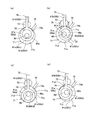
- FIG. 2 is a plan view showing the configuration of the cylinder 61 and the piston 62 of FIG. 1 and their operations.
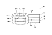
- FIG. 3 is a perspective view of the piston 62 of FIG. 4 is a cross-sectional view taken along line IV-IV in FIG.
- FIG. 5 is a cross-sectional view taken along line VV in FIG.
- the two cylinders 61 are arranged along the vertical direction of FIG. 1, and a substantially circular cylinder chamber in a plan view penetrating the cylinder 61 in the vertical direction at a substantially central portion thereof. 71 is formed.
- the upper and lower openings of the cylinder chamber 71 of the cylinder 61 disposed above are closed by the front head 63 and the middle plate 64, respectively.
- the openings at the upper and lower ends of the cylinder chamber 71 of the cylinder 61 disposed below are closed by the middle plate 64 and the rear head 65, respectively.
- the cylinder 61 accommodates blade constituent portions 81b and 82b, which will be described later, of the piston 62, which communicate with the cylinder chamber 71 and extend in the vertical direction of FIG. 2 above the cylinder chamber 71 in FIG.
- a blade storage chamber 75 is formed.
- the cylinder 61 is formed with an introduction flow path 72 extending rightward in FIG. 1 from the introduction port 71b formed in the right side portion of the side wall surface 71a of the cylinder chamber 71 in FIG.
- the discharge pipe 2 a of the accumulator 2 connected to is connected to the introduction flow path 72.
- the refrigerant introduced into the compressor 1 from the accumulator 2 flows into the cylinder chamber 71 (more specifically, a low-pressure chamber 71c described later) from the introduction port 71b via the introduction flow path 72.
- the piston 62 is configured by stacking two piston constituent members 81 and 82 in the vertical direction (the axial direction of the cylinder 61), and is disposed inside the two cylinder chambers 71, respectively.
- the piston component 81 includes a roller component 81a and a blade component 81b.
- the piston component 82 includes a roller component 82a and a blade component 82b.
- the piston component 81 and the piston component 82 are the same. It has the shape of
- the roller constituting portions 81 a and 82 a are both formed in an annular shape in a plan view, and are stacked inside each other and disposed inside the cylinder chamber 71.
- the blade constituting portions 81b and 82b are integrally formed with the roller constituting portions 81a and 82a, respectively, and extend upward in the drawing from the upper end portions in FIG. 2 of the outer peripheral surfaces 81c and 82c of the roller constituting portions 81a and 82a. Yes.
- the blade constituting portions 81b and 82b are stacked on each other, and the lower end portion in FIG. 2 connected to the roller constituting portions 81a and 82a is disposed in the cylinder chamber 71 together with the roller constituting portions 81a and 82a.
- the upper end portion is disposed in the blade storage chamber 75 and is slidably supported by a bush 73 disposed in the blade storage chamber 75.
- roller component 81a and the roller component 82a stacked on each other correspond to the roller according to the present invention
- the blade component 81b and the blade component 82b stacked on each other in the present invention corresponds to such a blade. That is, in the present embodiment, the roller and the blade are integrally formed. Therefore, as will be described later, when the piston 62 moves, the roller and the blade do not slide and burn-in does not occur.
- the shaft 60 described above penetrates the roller constituent portions 81 a and 82 a in the vertical direction, and an eccentric portion 60 a provided in the middle of the shaft 60 and whose center axis is deviated from the center axis of the shaft 60 is a roller configuration. It is fitted in the space inside the portions 81a and 82a.
- the roller constituting portions 81a and 82a are arranged so that the outer peripheral surfaces 81c and 82c thereof are located on the side of the cylinder chamber 71 as shown in FIGS. It moves to the clockwise direction of FIG. 2 along the side wall surface 71a so that it may contact
- the cylinder chamber 71 is divided into the low pressure chamber 71c and the high pressure chamber 71d by the piston 62, and the volumes of the low pressure chamber 71c and the high pressure chamber 71d change, and FIG.
- the outer peripheral surfaces 81c and 82c of the roller constituent portions 81a and 82a abut against the portion adjacent to the downstream side of the inlet port 71b on the side wall surface 71a of the cylinder chamber 71 with respect to the moving direction of the roller constituent portions 81a and 82a.
- the volume of the high pressure chamber 71d is reduced and the refrigerant in the high pressure chamber 71d is compressed.
- the refrigerant compressed to a predetermined pressure or higher in the high pressure chamber 71 d is discharged from the discharge port 74 to the sealed space 26.
- the refrigerant to be compressed next is introduced into the low pressure chamber 71c from the introduction port 71b.
- the height Hp / 2 of the piston constituent members 81 and 82 is such that the inner peripheral surfaces 81d and 82d of the roller constituent portions 81a and 82a and the shaft 60 ( The height is such that an oil film of the lubricating oil L is formed between the side surfaces of the eccentric portion 60a), so that the roller constituent portions 81a and 82a and the eccentric portion 60a are not in direct contact with each other. The occurrence of seizure due to contact between the two is prevented.
- the height Hp of the piston 62 is lower than the height Hs of the cylinder chamber 71, the gap between the upper surface of the roller component 81a and the upper wall surface of the cylinder chamber 71, and the roller component Lubricating oil L flows into the low-pressure chamber 71c from the inside of the roller constituting portions 81a and 82a through a gap between the lower surface of 82a and the lower wall surface of the cylinder chamber 71.
- the amount of the lubricating oil L flowing into the low pressure chamber 71c from the inside of the roller constituting portions 81a and 82a increases, the temperature of the refrigerant in the low pressure chamber 71c increases due to the lubricating oil L, and the performance of the compressor 1 decreases. There is a risk that.
- the gap between the upper surface of the blade component 81b and the upper wall surface of the cylinder chamber 71 and the gap between the lower surface of the blade component 82b and the lower wall surface of the cylinder chamber 71 are set in the high pressure chamber 71d.
- Lubricating oil L flows. Since the refrigerant is compressed in the high pressure chamber 71d as described above, the temperature of the refrigerant in the high pressure chamber 71d is high, and the amount of the lubricating oil L flowing from the high pressure chamber 71d into the low pressure chamber 71c increases. The lubricating oil L may increase the temperature of the refrigerant in the low pressure chamber 71c and reduce the performance of the compressor 1.
- the piston 62 is configured by stacking two piston constituent members 81 and 82 in the vertical direction, the upper surface of the piston constituent member 81 and the upper wall surface of the cylinder chamber 71 In addition to the gap between the lower surface of the piston component member 82 and the lower wall surface of the cylinder chamber 71, the lubricating oil L also flows between the piston component member 81 and the piston component member 82 to form an oil film. There is a gap.
- the height of the piston 62 ′ is Assuming that Hp is the same as the total height of the piston constituting members 81 and 82, the size B1 of the gap between the upper surface of the piston 62 'and the upper wall surface of the cylinder chamber 71 in this case, and the lower surface of the piston 62'
- the sum B1 + B2 of the size B2 of the gap between the cylinder chamber 71 and the wall surface of the cylinder chamber 71 is the size of the gap between the upper surface of the piston component 81 and the upper wall surface of the cylinder chamber 71 in this embodiment.
- the sizes A1, A2, and A3 of the gaps in the case of the present embodiment are substantially equal (that is, a size of about one third of the total of these gaps).
- the sizes B1 and B2 of the gaps in the conventional case are also substantially equal (that is, about a half of the total of these gaps). Therefore, in the case of the present embodiment, the sizes A1, A2, and A3 of the gaps in the present embodiment are as much as the gap between the piston component member 81 and the piston component member 82. 4 (b) and the size of each gap shown in FIG. 5 (b) is smaller than B1 and B2.
- the flow rate Q of the liquid flowing through the gap between the two flat plates is It is known that
- h is the size of the gap
- ⁇ is the viscosity of the lubricating oil L
- dp / dx is the pressure gradient. From this equation, since the flow rate Q of the liquid flowing through the gap between the flat plates is proportional to the cube of the gap size h, when there are a plurality of gaps and the total size of the gaps is the same, It can be seen that the larger the number and the smaller the size of each gap, the smaller the total liquid flow rate Q.
- the piston 62 when the piston 62 is configured by two piston constituent members 81 and 82 stacked in the vertical direction as in the present embodiment, the upper surface of the piston constituent member 81 and the upper wall surface of the cylinder chamber 71 The sizes A1, A2, and A3 of the gaps between the piston component member 82 and the lower wall surface of the cylinder chamber 71 and the gaps between the piston component member 81 and the piston component member 82 are reduced. Through these gaps, the amount of the lubricating oil L flowing into the roller constituting portions 81a and 82a and the low pressure chamber 71c from the high pressure chamber 71d can be reduced. Thereby, it can prevent that the temperature of the refrigerant
- the total size of the gaps A1 + A2 + A3 should be larger than the conventional total size of the gaps B1 + B2. That is, since the sum of the height of the piston component 81 and the height of the piston component 82 can be made lower than the height of the piston 62 ′, the piston 62 comes into contact with the upper and lower wall surfaces of the cylinder chamber 71 and the piston It is possible to reliably prevent the movement of 62 from being hindered.
- the upper surface of the piston component 81 and the cylinder chamber 71 are arranged.
- the upper wall surface, the lower surface of the piston component member 82 and the lower wall surface of the cylinder chamber 71 are arranged closer to each other, and the piston component members 81 and 82 come into contact with the upper and lower wall surfaces of the cylinder chamber 71. It is thought that it is easy to end up.
- FIG. 6A shows an oil film reaction force generated between the piston 62 and the eccentric portion 60a of the shaft 60 in the state where there is no gap between the two piston components 81 and 82, and the magnitude thereof.
- FIG. 6A shows an oil film reaction force generated between the piston 62 and the eccentric portion 60a of the shaft 60 in the state where there is no gap between the two piston components 81 and 82, and the magnitude thereof.
- the magnitude of this oil film reaction force is the central portion of the piston constituent members 81, 82 in the vertical direction, that is, between the piston constituent member 81 and the piston constituent member 82. Because the oil film reaction force causes the lubricating oil L to flow between the piston component member 81 and the piston component member 82, a gap is formed between them. Therefore, during the operation of the compressor 1, a gap is surely formed between the piston component member 81 and the piston component member 82.
- size of the said oil film reaction force after the clearance gap was made between the piston structural member 81 and the piston structural member 82 is the up-down direction of the piston structural members 81 and 82, as shown in FIG.6 (b).
- FIG. 6B shows an oil film reaction force generated between the piston 62 and the eccentric portion 60a of the shaft 60 in a state where a gap is formed between the two piston constituent members 81 and 82, and its magnitude. It is a figure which shows distribution of thickness.
- the piston 62 is constituted by two piston constituent members 81 and 82 stacked in the vertical direction, and the lubricating oil L flows between the blade constituent portion 81b and the blade constituent portion 82b. In addition, no heat is trapped between the blade constituent portion 81b and the blade constituent portion 82b, so that the above-described burn-in can be prevented.
- the compressor 1 can be used CO 2 as a refrigerant.
- CO 2 is used as the refrigerant, the pressure difference between the low pressure chamber and the high pressure chamber becomes particularly large, and the lubricating oil L tends to flow from the high pressure chamber 71d into the low pressure chamber 71c.
- the temperature of the refrigerant discharged from the compressor 1 becomes high when used in a hot water supply device, and therefore the temperature is lowered from the high pressure chamber 71d having a high temperature.
- the lubricating oil L flows into the low pressure chamber 71c, the temperature of the refrigerant in the low pressure chamber rises, and the compression efficiency of the refrigerant in the compressor 1 may decrease.
- HFO-1234yf 2,3,3,3-tetrafluoro-1-propene
- HFO-1225ye 1, 2, 3, 3-penta Fluoro-1-propene
- chemical formula is represented by CF 3 —CF ⁇ CHF
- 1, 3, 3, 3-tetrafluoro-1-propene referred to as “HFO-1234ze”.
- CHF 2 —CF ⁇ CHF 1, 2, 3, 3-tetrafluoro-1-propene
- HFO-1234ye 1, 2, 3, 3-tetrafluoro-1-propene
- CHF 2 —CF ⁇ CHF 1, 2, 3, 3-tetrafluoro-1-propene
- HFO-1234zf 3,3,3-trifluoro-1-propene
- the chemical formula is represented by CF 3 —CH ⁇ CH 2
- the above-mentioned refrigerants include HFC-32 (difluoroethane), HFC-125 (pentafluoroethane), HFC-134 (1, 1, 2, 2-tetrafluoroethane), HFC-134a (1, 1, 1, 1).
- HFC-143a (1,1,1-trifluoroethane)
- HFC-152a (1,1-difluoroethane)
- HFC-161 HFC-227ea
- HFC-236ea HFC-236fa
- the refrigerant as described above (C 3 H m F n) is the coefficient of performance of the theoretical (COP) is relatively high, the coefficient of performance of the apparatus using the compressor 1 (COP) is improved. Further, it is known that such a refrigerant does not contain chlorine atoms, bromine atoms, or the like and has a small influence on the destruction of the ozone layer (low global warming potential (GWP)).
- GWP global warming potential
- the refrigerant as described above has a relatively low refrigeration capacity per unit volume, it is necessary to increase the volume of the cylinder chamber 71 as compared with the case where other refrigerants are used. At this time, it is conceivable to increase the height of the cylinder chamber 71 in order to increase the volume of the cylinder chamber 71. However, when the height of the cylinder chamber 71 is increased, the cylinder chamber 71 is disposed in the cylinder chamber 71. The piston height also increases. Therefore, when the piston is constituted by a single member as in the prior art (for example, like the piston 62 ′ shown in FIG. 4B and FIG. 5B), it is particularly at the center of the blade portion of the piston. Heat tends to be trapped, and baking tends to occur.
- the piston 62 is configured by stacking the piston component member 81 and the piston component member 82, and therefore, between the blade component part 81b and the blade component part 82b. It is possible to reliably prevent the occurrence of burn-in as described above without heat accumulation.
- the above-described refrigerant is preferably used in a situation where it is difficult to reach a high temperature because the refrigerant is likely to be decomposed at a high temperature, but in this embodiment, as described above, the piston that is likely to have a high temperature. Since the portion between the piston component 81 and the piston component 82 of the piston 62 corresponding to the substantially central portion in the vertical direction of 62 ′ is cooled by the lubricating oil L, the refrigerant is prevented from being decomposed. can do.
- the piston 62 is configured by the two piston constituent members 81 and 82 that are stacked in the vertical direction, the upper surface of the piston constituent member 18 and the cylinder chamber 71.
- the size of each gap Since the sizes A1, A2 and A3 are smaller than the sizes B1 and B2 of the respective gaps in the conventional case, the inner side of the roller constituting portions 81a and 82a and the high pressure chamber 71d. It is possible to reduce the amount of lubricant L which flows in Luo low-pressure chamber 71c. Thereby, it becomes difficult for the temperature of the refrigerant
- the sum total of the height of the piston structural members 81 and 82 can be made small, and piston structural members 81 and 82 are cylinders. Contact with the upper and lower wall surfaces of the chamber 71 can be reliably prevented.
- piston constituent members 81 and 82 are formed integrally with the roller constituent portion 81a and the blade constituent portion 81b, and the roller constituent portion 82a and the blade constituent portion 82b, respectively, It is possible to prevent seizure from occurring due to sliding of the 81a and the blade constituting portion 81b and the roller constituting portion 82a and the blade constituting portion 82b.
- the piston 62 is configured by the two piston constituent members 81 and 82 stacked in the vertical direction, but is not limited thereto.
- the piston 90 is configured by three piston constituent members 91, 92, 93 having a height of about Hp / 3, which are stacked in the vertical direction (Modified Example 1). .
- the lubricating oil L flows between the piston component 91 and the piston component 92 and between the piston component 92 and the piston component 93 to form an oil film. Since there is a gap, a gap between the upper surface of the piston component member 91 and the upper wall surface of the cylinder chamber 71 (see FIG. 4), a gap between the lower surface of the piston component member 93 and the lower wall surface of the cylinder chamber 71, and The size of the gap between the piston constituent members 91 to 93 is smaller than the conventional one (specifically, the above-described B1 and B2).
- lubrication flows into the low-pressure chamber 71c (see FIG. 4) from the high-pressure chamber 71d (see FIG. 4) and the roller constituent portions 91a, 92a, and 93a through these gaps.
- the amount of oil L can be reduced.
- the lubricating oil L flows between the blade constituent portions 91b, 92b, and 93b, it is possible to prevent heat from being burned and burnt in the portion between the blade constituent portions 91b, 92b, and 93b. .
- the height Hp / 3 of each of the piston constituent members 91 to 93 is between the inner peripheral surfaces 91d, 92d, 93d of the roller constituent portions 91a, 92a, 93a and the eccentric portion 60a.
- the height is such that an oil film of the lubricating oil L can be formed.
- the piston may be configured by stacking four or more piston constituent members in the vertical direction.
- the height of each piston component decreases, so the number of piston components depends on the inner peripheral surface of the roller component. It is necessary to make the number more than the minimum height at which an oil film is formed between the first and second eccentric portions 60a.
- the piston component members 81 and 82 are integrally formed with the roller component portion 81a and the blade component portion 81b, and the roller component portion 82a and the blade component portion 82b, respectively.
- the roller and the blade are integrally formed, but the present invention is not limited to this.
- a substantially annular roller 101 in a plan view is disposed in the cylinder chamber 71, and the blade 102 includes a cylinder chamber 71 and a blade storage chamber 105. It is arranged across.
- a spring 103 that presses the blade 102 toward the roller 101 downward in FIG. 8 is disposed at the upper end of the blade storage chamber 105 in FIG.
- the roller 101 is composed of two roller constituent members 111 and 112 stacked in the vertical direction, and the blade 102 is configured of two blade constituent members 113 and 114 stacked in the vertical direction ( Modification 2).
- the upper surface of the roller component member 111, the lower surface of the blade component member 113, and the upper surface of the cylinder chamber 71 are the same as in the above-described embodiment.
- a gap between the wall surface, a lower surface of the roller component member 112, a gap between the lower surface of the roller component member 112 and the lower wall surface of the cylinder chamber 71, a gap between the roller component member 111 and the roller component member 112, and The gap between the blade constituent member 113 and the blade constituent member 114 is reduced, and the amount of lubricating oil L flowing into the low pressure chamber 71c from the inside of the roller constituent members 111 and 112 and the high pressure chamber 71d is reduced.
- the lubricating oil L also flows between the blade constituent member 113 and the blade constituent member 114, heat is burnt into the portion between the blade constituent member 113 and the blade constituent member 114 as in the above-described embodiment. The occurrence of sticking is prevented.
- the refrigerant when a refrigerant containing C 3 H m F n as described in the above embodiment is used as the refrigerant, the refrigerant is easily decomposed when the temperature is high, and thus is used in a situation where the temperature is difficult to rise. It is desirable.
- the compressor in which the roller and the blade are separated as in the second modification heat is generated by sliding between the roller and the blade, and this portion of the compressor is likely to become high temperature.
- the roller 101 is configured by the two roller constituent members 111 and 112 stacked in the vertical direction
- the blade 102 is configured by the two blades stacked in the vertical direction. Since the members 113 and 114 are configured, the lubricating oil L flows between the roller constituent member 111 and the roller constituent member 112 and between the blade constituent member 113 and the blade constituent member 114. This part of the compressor is cooled. Therefore, it is possible to prevent the refrigerant from being decomposed due to the temperature rise of the compressor.
- the roller 101 is configured by the two roller constituent members 111 and 112 and the blade 102 is configured by the two blade constituent members 113 and 114.
- the present invention is not limited thereto. Absent.
- the roller 101 includes two roller constituent members 111 and 112 as in the second modification, but the blade 102 includes one member. (Modification 3). Even in this case, the amount of the lubricating oil L flowing into the low-pressure chamber 71c from the inside of the roller constituent members 111 and 112 can be reduced as in the above-described embodiment.
- the blade 102 is configured by two blade constituent members 113 and 114 as in the modified example 2, but the roller 101 is configured by one member. (Modification 4). Even in this case, the amount of the lubricating oil L flowing from the high pressure chamber 71d into the low pressure chamber 71c can be reduced, and the portion between the blade component member 113 and the blade component member 114 can be heated as in the above-described embodiment. It is possible to prevent the occurrence of burning burning.
- roller 101 is composed of a plurality of roller constituent members and the blade 102 is composed of a plurality of blade constituent members
- the number of roller constituent members and the number of blade constituent members are different from each other. Also good. Even in this case, the same effects as those of the above-described modification 2 can be obtained.
- the shaft 60 extends in the vertical direction (the axial direction of the cylinder 61 is the vertical direction), and the piston components 81 and 82 are stacked in the vertical direction.
- the shaft extends in the horizontal direction (when the axial direction of the cylinder is the horizontal direction)
- a plurality of piston constituent members may be stacked in the extending direction of the shaft (axial direction of the cylinder). Good.
- the amount of lubricating oil flowing into the low pressure chamber can be reduced, and the lubricant can prevent the temperature of the refrigerant in the low pressure chamber from rising and the performance of the compressor from being deteriorated. it can.
Landscapes
- Engineering & Computer Science (AREA)
- Mechanical Engineering (AREA)
- General Engineering & Computer Science (AREA)
- Applications Or Details Of Rotary Compressors (AREA)
Abstract
圧縮機において高温の潤滑油が低圧室に流れ込んで性能が低下してしまうのを防止する。
シリンダ室には、ピストン62が配置されており、ピストン62がシリンダ室71内を移動することにより、シリンダ室流れ込んだ冷媒が圧縮される。ピストン62は、上下方向(シリンダの軸方向)に積層された2つのピストン構成部材81、82によって構成されている。ピストン構成部材81、82は、それぞれ、シリンダ室の側壁面に当接するように、シリンダ室の側壁面に沿って移動することによって、シリンダ室を高圧室と低圧室とに分断するとともに高圧室及び低圧室の容積を変化させる円環状のローラ構成部81a、82a、及び、ローラ構成部81a、81bと一体的に形成されており、ローラ構成部81a、82aとともに、シリンダ室を高圧室と低圧室とに分断するブレード構成部81b、82bを有している。
Description
本発明は、冷媒を圧縮する圧縮機に関する。
特許文献1に記載の圧縮機においては、シリンダの内部に形成されたシリンダ室の内部にローラとブレードとが一体的に形成されたピストンが配置されており、ピストンによってシリンダ室が吸入室(低圧室)と吐出室(高圧室)とに分断されている。そして、ローラがシリンダ室の側壁面に当接しながらこの側壁面に沿って移動することにより、吐出室の容積が変化して吐出室内の冷媒が圧縮される。
特開2004-124948号公報
ここで、特許文献1に記載の圧縮機では、シリンダ室の上下壁面との接触することによってピストンの移動が妨げられてしまうのを防止するため、ピストン(ローラ及びブレード)は、シリンダ室よりも高さが低くなっている。そして、ローラがシリンダ室よりも高さが低くなっているため、ローラとシリンダ室の上下壁面との隙間を介して、ローラの内側を流れる潤滑油が低圧室に流れ込む。しかしながら、ローラの内側から低圧室に流れ込む潤滑油の量が多くなると、この潤滑油によって低圧室内の冷媒の温度が上昇してしまい、圧縮機の性能が低下してしまう。
また、ブレードがシリンダ室よりも高さが低くなっているため、ブレードとシリンダ室の上下壁面との隙間を介して、高圧室から低圧室に潤滑油が流れ込む。ここで、高圧室においては冷媒の圧縮が行われるため、高圧室の温度は高くなっており、これにより高圧室内の潤滑油の温度も高くなっている。したがって、高圧室から低圧室に流れ込む潤滑油の量が多くなると、低圧室内の冷媒の温度が上昇してしまい、圧縮機の性能が低下してしまう。
本発明の目的は、低圧室に流れ込む上記潤滑油の量が少なく、性能が低下しない圧縮機を提供することである。
第1の発明に係る圧縮機は、密閉空間内に配置されており、内部にシリンダ室が設けられたシリンダと、前記シリンダ室の内部に配置されており、その外周面が前記シリンダ室の側壁面に当接するように当該側壁面に沿って移動して、前記シリンダ室を、冷媒の圧縮が行われるとともに圧縮された冷媒を前記密閉空間に排出する高圧室と、外部から冷媒が導入される低圧室とに分断するとともに、前記高圧室及び前記低圧室の容積を変化させる環状のローラと、前記シリンダ室の内部に配置されており、前記ローラとともに前記シリンダ室を前記高圧室と前記低圧室とに分断するブレードとを備えており、前記ローラは、前記シリンダの軸方向に積層された複数のローラ構成部材によって構成されていることを特徴としている。
この圧縮機では、シリンダの軸方向に積層された複数のローラ構成部材によってローラが構成されているため、圧縮機の駆動中にはローラ構成部材の間に潤滑油の油膜が形成され、ローラ構成部材の間に隙間ができることになり、ローラ構成部材とシリンダ室におけるシリンダの軸方向に関する両側の壁面との間の隙間の大きさ、及び、ローラ構成部材間の隙間の大きさが、従来のようにローラが1つの部材によりできている場合のローラとシリンダ室におけるシリンダの軸方向に関する両側の壁面との間の隙間の大きさよりも小さくなる。一方、流体力学の観点から、隙間に流れる液体の量は、隙間の大きさの合計が同じ場合には、隙間の数が多く1つの隙間の大きさが小さいほど少なくなることが知られている。
したがって、ローラ構成部材とシリンダ室におけるシリンダの軸方向に関する両側の壁面との間の隙間の大きさ、及び、ローラ構成部材間の隙間の大きさの合計が、従来のようにローラを1つの部材によって構成した場合のローラとシリンダ室におけるシリンダの軸方向に関する両側の壁面との隙間の大きさの合計と同じであっても、低圧室に流れる潤滑油の量を低減することができる。
あるいは、低圧室内に流れ込む潤滑油の量を従来と同程度にする場合には、ローラ構成部材とシリンダ室におけるシリンダの軸方向に関する両側の壁面との間の隙間の大きさ、及び、ローラ構成部材間の隙間の大きさの合計を、従来のようにローラを1つの部材によって構成した場合のローラとシリンダ室におけるシリンダの軸方向に関する両側の壁面との隙間の大きさの合計よりも大きくすることができ、ローラ構成部材がシリンダ室におけるシリンダの軸方向に関する両側の壁面に接触してしまうのを確実に防止することができる。
なお、この圧縮機においては、ローラ構成部材の間に隙間ができた分だけ、ローラ構成部材とシリンダ室におけるシリンダの軸方向に関する両側の壁面との距離が短くなっているが、シリンダ及びピストンの線膨張変形量の違いによりシリンダ室におけるシリンダの軸方向に関する両側の壁面がローラ構成部材に近づいたときには、油膜が押しつぶされることによってローラ構成部材間の隙間が小さくなるため、従来の場合と比較してローラがシリンダ室におけるシリンダの軸方向に関する両側の壁面に接触してしまいやすいということもない。
第2の発明に係る圧縮機は、第1の発明に係る圧縮機であって、前記ブレードが前記シリンダの軸方向に積層された複数のブレード構成部材によって構成されていることを特徴としている。
この圧縮機では、積層された複数のブレード構成部材によってブレードが構成されているため、ブレード構成部材との間に潤滑油の油膜ができてブレード構成部材の間に隙間ができ、ブレード構成部材とシリンダ室におけるシリンダの軸方向に関する両側の壁面との間の隙間の大きさ、及び、ブレード構成部材の間の隙間の大きさが、従来のようにブレードが1つの部材によって構成されている場合のブレードとシリンダ室におけるシリンダの軸方向に関する両側の壁面との間の隙間の大きさよりも小さくなる。
したがって、ブレード構成部材とシリンダ室におけるシリンダの軸方向に関する両側の壁面との間の隙間の大きさ、及び、ブレード構成部材間の隙間の大きさの合計が、従来のようにブレードを1つの部材によって構成した場合のブレードとシリンダ室におけるシリンダの軸方向に関する両側の壁面との隙間の大きさの合計と同じであっても、高圧室から低圧室に流れる潤滑油の量を低減することができる。
あるいは、高圧室から低圧室に流れ込む潤滑油の量を従来と同程度にする場合には、ブレード構成部材とシリンダ室の上下壁面との間の隙間の大きさ、及び、ブレード構成部材間の隙間の大きさの合計を、従来のようにブレードを1つの部材によって構成した場合のブレードとシリンダ室におけるシリンダの軸方向に関する両側の壁面との隙間の大きさの合計よりも大きくすることができ、ブレード構成部材がシリンダ室におけるシリンダの軸方向に関する両側の壁面に接触してしまうのを確実に防止することができる。
さらに、ブレードが1つの部材によって構成されている場合には、ブレードの高さ方向に関する中央部に熱がこもってしまい焼きつきが発生してしまう虞があるが、この圧縮機では、複数のブレード構成部材が積層されることによってブレードが形成されているため、ブレード構成部材の間の隙間に潤滑油が流れ、上述したような焼きつきが生じにくい。
なお、この圧縮機においては、ブレード構成部材の間に隙間ができた分だけ、ブレード構成部材とシリンダ室におけるシリンダの軸方向に関する両側の壁面との距離が短くなっているが、シリンダ及びピストンの線膨張変形量の違いによりシリンダ室におけるシリンダの軸方向に関する両側の壁面がブレード構成部材に近づいたときには、油膜が押しつぶされることによってブレード構成部材間の隙間が小さくなるため、従来の場合と比較してブレードがシリンダ室におけるシリンダの軸方向に関する両側の壁面に接触してしまいやすいということもない。
第3の発明に係る圧縮機は、密閉空間内に配置されており、内部にシリンダ室が設けられたシリンダと、前記シリンダ室の内部に配置されており、その外周面が前記シリンダ室の側壁面に当接するように当該側壁面に沿って移動して、前記シリンダ室を、冷媒の圧縮が行われるとともに圧縮された冷媒を前記密閉空間に排出する高圧室と、外部から冷媒が導入される低圧室とに分断するとともに、前記高圧室及び前記低圧室の容積を変化させる環状のローラと、前記シリンダ室の内部に配置されており、前記ローラとともに前記シリンダ室を前記高圧室と前記低圧室とに分断するブレードとを備えており、前記ブレードは、前記シリンダの軸方向に積層された複数のブレード構成部材によって構成されていることを特徴としている。
この圧縮機では、第2の発明に係る圧縮機と同様の効果を得ることができる。
第4の発明に係る圧縮機は、密閉空間内に配置されており、内部にシリンダ室が設けられたシリンダと、前記シリンダ室の内部に配置されたピストンとを備えており、前記ピストンは、その外周面が前記シリンダ室の側壁面に当接するように当該側壁面に沿って移動して、前記シリンダ室を、冷媒の圧縮が行われるとともに圧縮された冷媒を前記密閉空間に排出する高圧室と、外部から冷媒が導入される低圧室とに分断するとともに、前記高圧室及び前記低圧室の容積を変化させる環状のローラと、前記ローラと一体的に形成されており、前記ローラとともに前記シリンダ室を前記高圧室と前記低圧室とに分断するブレードとを有しているとともに、前記シリンダの軸方向に積層された複数のピストン構成部材によって構成されていることを特徴としている。
この圧縮機では、ローラとブレードとが一体的に形成されたピストンが、シリンダの軸方向に積層された複数のピストン構成部材によって構成されているため、第1~第3の発明に係る圧縮機と同様の効果を得ることができるとともに、ローラとブレードとが一体的に形成されているので、両者が摺動して焼きつきが生じてしまうのを防止することができる。
以上の説明に述べたように、本発明によれば、以下の効果が得られる。
第1の発明では、ローラ構成部材とシリンダ室におけるシリンダの軸方向に関する両側の壁面との間の隙間の大きさ、及び、ローラ構成部材間の隙間の大きさの合計が、従来のようにローラを1つの部材によって構成した場合のローラとシリンダ室におけるシリンダの軸方向に関する両側の壁面との隙間の大きさの合計と同じであっても、低圧室に流れる潤滑油の量を低減することができる。
あるいは、第1の発明では、低圧室内に流れ込む潤滑油の量を従来と同程度にする場合には、ローラ構成部材とシリンダ室におけるシリンダの軸方向に関する両側の壁面との間の隙間の大きさ、及び、ローラ構成部材間の隙間の大きさの合計を、従来のようにローラを1つの部材によって構成した場合のローラとシリンダ室におけるシリンダの軸方向に関する両側の壁面との隙間の大きさの合計よりも大きくすることができ、ローラ構成部材がシリンダ室におけるシリンダの軸方向に関する両側の壁面に接触してしまうのを確実に防止することができる。
第2の発明では、ブレード構成部材とシリンダ室におけるシリンダの軸方向に関する両側の壁面との間の隙間の大きさ、及び、ブレード構成部材間の隙間の大きさの合計が、従来のようにブレードを1つの部材によって構成した場合のブレードとシリンダ室におけるシリンダの軸方向に関する両側の壁面との隙間の大きさの合計と同じであっても、高圧室から低圧室に流れる潤滑油の量を低減することができる。
あるいは、第2の発明では、高圧室から低圧室に流れ込む潤滑油の量を従来と同程度にする場合には、ブレード構成部材とシリンダ室におけるシリンダの軸方向に関する両側の壁面との間の隙間の大きさ、及び、ブレード構成部材間の隙間の大きさの合計を、従来のようにブレードを1つの部材によって構成した場合のブレードとシリンダ室におけるシリンダの軸方向に関する両側の壁面との隙間の大きさの合計よりも大きくすることができ、ブレード構成部材がシリンダ室におけるシリンダの軸方向に関する両側の壁面に接触してしまうのを確実に防止することができる。
さらに、ブレードが1つの部材によって構成されている場合には、ブレードの高さ方向に関する中央部に熱がこもってしまい焼きつきが発生してしまう虞があるが、第2の発明では、複数のブレード構成部材が積層されることによってブレードが形成されているため、ブレード構成部材の間の隙間に潤滑油が流れ、上述したような焼きつきが生じにくい。
第3の発明では、第2の発明と同様の効果を得ることができる。
第4の発明では、ローラとブレードとが一体的に形成されたピストンが、シリンダの軸方向に積層された複数のピストン構成部材によって構成されているため、第1~第3の発明と同様の効果を得ることができるとともに、ローラとブレードとが一体的に形成されているので、両者が摺動して焼きつきが生じてしまうのを防止することができる。
1 圧縮機
12 モータ
13 圧縮機構
24 導入口
26 密閉空間
61 シリンダ
62 ピストン
71 シリンダ室
71a 側壁面
71c 低圧室
71d 高圧室
81、82 ピストン構成部材
81a、82a ローラ構成部
81b、82b ブレード構成部
81c、82c 外周面
91、92、93 ピストン構成部材
101 ローラ
102 ブレード
111、112 ローラ構成部材
113、114 ブレード構成部材
12 モータ
13 圧縮機構
24 導入口
26 密閉空間
61 シリンダ
62 ピストン
71 シリンダ室
71a 側壁面
71c 低圧室
71d 高圧室
81、82 ピストン構成部材
81a、82a ローラ構成部
81b、82b ブレード構成部
81c、82c 外周面
91、92、93 ピストン構成部材
101 ローラ
102 ブレード
111、112 ローラ構成部材
113、114 ブレード構成部材
以下、本発明に係る圧縮機の実施の形態について図面を参照しつつ説明する。
図1は、本実施の形態に係る圧縮機の概略構成図である。圧縮機1は、例えば、エアコンなどの空調装置に用いられる圧縮機であり、アキュムレータ2から導入される、水分が除去された冷媒を圧縮して、その上端部に配置された排出流路25から圧縮した冷媒を排出する。図1に示すように、圧縮機1は、ケーシング11、モータ12及び圧縮機構13を備えている。
ケーシング11は、胴体21、トップ22及びボトム23によって構成されている。胴体21は、上下方向に延びた略円筒状の部材であり、その上下端が開口している。また、胴体21の側面には右下端部にアキュムレータ2の、冷媒を排出する排出管2aが接続される接続口24が上下方向に沿って2つ形成されている。トップ22は、胴体21の上端の開口を塞ぐ部材である。また、トップ22には、前述した排出流路25が設けられている。ボトム23は胴体21の下端の開口を塞ぐ部材である。そして、ケーシング11には、胴体21、トップ22及びボトム23によって囲まれた密閉空間26が形成されている。
モータ12は、密閉空間26内に配置されており、固定子31と回転子32とを有している。固定子31は、胴体21の内壁面に固定されている。回転子32は、固定子31の径方向内側に配置されており、その略中央部には、上下方向に延びたシャフト60の上端部が固定されている。そして、モータ12においては、固定子31と回転子32との間に発生する磁力によって回転子がシャフト60とともに回転する。なお、固定子31及び回転子32の構成は、従来のモータのものと同様であるので、ここではその詳細な説明を省略する。
圧縮機構13は、密閉空間26内に配置されており、モータ12の下方に位置している。圧縮機構13は、ローラとブレードとが一体的に形成されたいわゆるロータリー型の圧縮機構であり、図1に示すように、シリンダ61、ピストン62、フロントヘッド63、ミドルプレート64及びリアヘッド65を有している。図2は図1のシリンダ61及びピストン62の構成及びこれらの動作を示す平面図である。図3は図2のピストン62の斜視図である。図4は図2のIV-IV線断面図である。図5は図2のV-V線断面図である。
図1~図5に示すように、2つのシリンダ61は、図1の上下方向に沿って配置されており、その略中央部にシリンダ61を上下方向に貫通する平面視で略円形のシリンダ室71が形成されている。そして、上方に配置されたシリンダ61のシリンダ室71の上下の開口が、それぞれ、フロントヘッド63及びミドルプレート64によって塞がれている。一方、下方に配置されたシリンダ61のシリンダ室71の上下端の開口が、それぞれ、ミドルプレート64及びリアヘッド65によって塞がれている。
また、シリンダ61には、シリンダ室71の図2における上方に、シリンダ室71に連通しているとともに図2の上下方向に延びた、ピストン62の後述するブレード構成部81b、82bが収納されるブレード収納室75が形成されている。
さらに、シリンダ61には、シリンダ室71の側壁面71aの図1における右側の部分に形成された導入口71bから図1の右方に延びた導入流路72が形成されており、接続口24に接続されたアキュムレータ2の排出管2aが導入流路72に接続される。これにより、アキュムレータ2から圧縮機1に導入された冷媒は、導入流路72を介して導入口71bからシリンダ室71(より詳細には、後述する低圧室71c)に流れ込むことになる。
ピストン62は、2つのピストン構成部材81、82が上下方向(シリンダ61の軸方向)に積層されることによって構成されており、2つのシリンダ室71の内部にそれぞれ配置されている。ピストン構成部材81は、ローラ構成部81aとブレード構成部81bとからなり、ピストン構成部材82は、ローラ構成部82aとブレード構成部82bとからなり、ピストン構成部材81とピストン構成部材82とは同様の形状を有している。
ローラ構成部81a、82aは、ともに平面視で円環状に構成されており、互いに積層されてシリンダ室71の内部に配置されている。ブレード構成部81b、82bは、それぞれ、ローラ構成部81a、82aと一体的に構成されており、ローラ構成部81a、82aの外周面81c、82cの図2における上端部から図中上方に延びている。
また、ブレード構成部81b、82bは、互いに積層されており、ローラ構成部81a、82aに接続された図2における下端部がローラ構成部81a、82aとともにシリンダ室71内に配置されているとともに、その上端部がブレード収納室75内に配置されており、同じくブレード収納室75内に配置されたブッシュ73に摺動可能に支持されている。
なお、ローラ構成部81aとローラ構成部82aとが互いに積層されたものが、本発明に係るローラに相当し、ブレード構成部81bとブレード構成部82bとが互いに積層されたものが、本発明に係るブレードに相当する。すなわち、本実施の形態においては、ローラとブレードとが一体的に形成されている。したがって、後述するように、ピストン62が移動したときに、ローラとブレードとが摺動して焼きつきが発生してしまうことがない。
そして、上述したシャフト60がローラ構成部81a、82aを上下方向に貫通しており、シャフト60の途中に設けられた、その中心軸がシャフト60の中心軸からずれた偏心部60aが、ローラ構成部81a、82aの内側の空間にはめ込まれている。これにより、ピストン62においては、シャフト60が回転すると、ローラ構成部81a、82aが、図2(a)~図2(d)に示すように、その外周面81c、82cがシリンダ室71の側壁面71aに当接するように、側壁面71aに沿って図2の時計回り方向に移動する。
このようにピストン62が移動することにより、シリンダ室71はピストン62によって低圧室71cと高圧室71dとに分断されるとともに、低圧室71c及び高圧室71dの容積が変化し、図2(b)に示すように、ローラ構成部81a、82aの外周面81c、82cが、ローラ構成部81a、82aの移動方向に関してシリンダ室71の側壁面71aにおける導入口71b下流側に隣接する部分に当接した状態となった後、図2(d)に示す状態となるまでの間、高圧室71dの容積が低下して高圧室71d内の冷媒が圧縮される。そして、図2(d)の状態になったときに、高圧室71d内の所定の圧力以上に圧縮された冷媒が排出口74から密閉空間26に排出される。この間、低圧室71cには、次に圧縮される冷媒が、導入口71bから導入されている。上述したような動作が繰り返されることにより、密閉空間26には圧縮された冷媒が溜まり、密閉空間26内に溜まった冷媒が、排出流路25から外部に排出される。
このとき、ピストン62がシリンダ室71の上下壁面(シリンダ室71におけるシリンダ61の軸方向に関する両側の壁面)、すなわち、フロントヘッド63、ミドルプレート64及びリアヘッド65に接触してピストン62の移動が妨げられてしまうのを防止するため、図4、5に示すように、ピストン62の高さ、すなわち、2つのピストン構成部材81、82の高さの合計Hp(=[Hp/2]+[Hp/2])が、シリンダ室71の高さHsよりも低くなっている。
ただし、ピストン構成部材81、82の高さが低すぎると、ローラ構成部81a、82aの内周面81d、82dと偏心部60aの側面との間に潤滑油Lの油膜が形成されず、ピストン構成部材81、82と偏心部60aとが直接接触して焼きつきが発生してしまう虞がある。しかしながら、本実施の形態においては、ピストン構成部材81、82の高さHp/2が、図4(a)に示すように、ローラ構成部81a、82aの内周面81d、82dとシャフト60(偏心部60a)の側面との間に潤滑油Lの油膜が形成される程度の高さとなっており、これにより、ローラ構成部81a、82aと偏心部60aとが直接接触してしまうことがなく、両者が接触して焼きつきが発生してしまうのが防止されている。
このように、ピストン62の高さHpがシリンダ室71の高さHsよりも低くなっているため、ローラ構成部81aの上面とシリンダ室71の上壁面との間の隙間、及び、ローラ構成部82aの下面とシリンダ室71の下壁面との間の隙間を介して、ローラ構成部81a、82aの内側から低圧室71cに潤滑油Lが流れ込む。そして、ローラ構成部81a、82aの内側から低圧室71cに流れ込む潤滑油Lの量が多くなると、この潤滑油Lによって低圧室71c内の冷媒の温度が上昇し、圧縮機1の性能が低下してしまう虞がある。
さらに、ブレード構成部81bの上面とシリンダ室71の上壁面との間の隙間、及び、ブレード構成部82bの下面とシリンダ室71の下壁面との間の隙間を介して、高圧室71d内の潤滑油Lが流れ込む。高圧室71dにおいては、上述したように冷媒の圧縮が行われるため、高圧室71d内の冷媒の温度は高くなっており、高圧室71dから低圧室71cに流れ込む潤滑油Lの量が多くなると、この潤滑油Lによって低圧室71c内の冷媒の温度が上昇し、圧縮機1の性能が低下してしまう虞がある。
しかしながら、本実施の形態では、ピストン62が2つのピストン構成部材81、82が上下方向に互いに積層されることによって構成されているため、ピストン構成部材81の上面とシリンダ室71の上壁面との間、及び、ピストン構成部材82の下面とシリンダ室71の下壁面との間に加え、ピストン構成部材81とピストン構成部材82との間にも潤滑油Lが流れ込んで油膜が形成されることにより隙間ができる。
したがって、図4(b)、図5(b)に示すように、ピストン62’が、従来のように1つの部材によって構成されている場合と比較した場合、ピストン62’の高さを2つのピストン構成部材81、82の高さの合計と同じHpとすると、この場合の、ピストン62’の上面とシリンダ室71の上壁面との間の隙間の大きさB1、及び、ピストン62’の下面とシリンダ室71のした壁面との間の隙間の大きさB2の合計B1+B2が、本実施の形態の場合の、ピストン構成部材81の上面とシリンダ室71の上壁面との間の隙間の大きさA1、ピストン構成部材82の下面とシリンダ室71の下壁面との間の隙間の大きさA2、及び、ピストン構成部材81とピストン構成部材82との間の隙間の大きさA3の合計A1+A2+A3と同じになる。
また、本実施の形態の場合の上記隙間の大きさA1、A2、A3はほぼ均等(すなわち、これらの隙間の合計の3分の1程度の大きさ)になっている。一方、従来の場合の上記隙間の大きさB1、B2もほぼ均等(すなわち、これらの隙間の合計の2分の1程度の大きさ)になっている。したがって、本実施の形態の場合には、ピストン構成部材81とピストン構成部材82との間に隙間ができている分だけ、本実施の形態における各隙間の大きさA1、A2、A3は、図4(b)、図5(b)に示す各隙間の大きさB1、B2よりも小さくなっている。
ここで、流体力学の観点から、2枚の平板間の隙間を流れる液体の流量Qは、

であることが知られている。ここで、hは隙間の大きさ、μは潤滑油Lの粘度、dp/dxは圧力勾配である。そして、この式から、平板間の隙間を流れる液体の流量Qは、隙間の大きさhの3乗に比例するため、隙間が複数あり、隙間の大きさの合計が同じ場合には、隙間の数が多く各隙間の大きさが小さいほうが、液体の流量Qの合計が少なくなることが分かる。
したがって、本実施の形態のように、ピストン62が上下方向に積層された2つのピストン構成部材81、82によって構成されている場合には、ピストン構成部材81の上面とシリンダ室71の上壁面との間の隙間、ピストン構成部材82の下面とシリンダ室71の下壁面との隙間、及び、ピストン構成部材81とピストン構成部材82との間の隙間の大きさA1、A2、A3を小さくすることができ、これらの隙間を介して、ローラ構成部81a、82aの内部、及び、高圧室71dから低圧室71cに流れ込む潤滑油Lの量を低減することができる。これにより、高温の潤滑油Lによって低圧室71c内の冷媒の温度が上昇してしまうのが防止され、圧縮機1の性能が低下してしまうのを防止することができる。
あるいは、低圧室71cに流れ込む上記潤滑油Lの量が従来と同じであってもよい場合には、上記隙間の大きさの合計A1+A2+A3を、従来の隙間の大きさの合計B1+B2よりも大きくすることができ、すなわち、ピストン構成部材81の高さとピストン構成部材82の高さの合計をピストン62’の高さよりも低くすることができるので、ピストン62がシリンダ室71の上下壁面に接触してピストン62の移動が妨げられてしまうのを確実に防止することができる。
ここで、本実施の形態の場合には、上記隙間の大きさA1、A2が、従来の隙間の大きさB1、B2よりも小さくなっていることから、ピストン構成部材81の上面とシリンダ室71の上壁面、及び、ピストン構成部材82の下面とシリンダ室71の下壁面とが、それぞれより近接して配置されることになり、ピストン構成部材81、82がシリンダ室71の上下壁面に接触してしまいやすいとも考えられる。
しかしながら、シリンダ61とピストン62の線膨張変形量の違いなどにより、ピストン構成部材81、82とシリンダ室71の上下壁面とが近づいたときには、ピストン構成部材81、82とシリンダ室71の上下壁面との間、及び、ピストン構成部材81とピストン構成部材82と間の潤滑油Lによって形成される油膜が押しつぶされることによってピストン構成部材81とピストン構成部材82とが互いに近づく方向に移動し(つまり、隙間の大きさA3が小さくなり)、ピストン構成部材81及びピストン構成部材82が、両者の間の隙間がなくなるまで移動すれば、ピストン構成部材81の上面とシリンダ室71の上壁面との間、及び、ピストン構成部材82の下面とシリンダ室71の下壁面との間に、従来のピストン62’の場合と同じだけの隙間ができることになるので、従来と比較して、ピストン62がシリンダ室71の上下壁面に接触してしまいやすいということはない。
また、ここで、ピストン構成部材81とピストン構成部材82とが上下方向に積層されていたとしても、上述したのとは異なり、ピストン構成部材81とピストン構成部材82との間に隙間ができなければ(図4(a)、図5(a)のA3=0であれば)、ピストン構成部材81、82とシリンダ室71の上下壁面との距離A1、A2が、それぞれ、図4(b)、図5(b)に示す距離B1、B2と同程度になってしまう、つまり、距離A1、A2が、距離B1、B2と比較して小さくならないとも考えられる。
しかしながら、本実施の形態では、図6(a)に示すように、ピストン構成部材81とピストン構成部材82との間に隙間がない状態で、シャフト60が回転してピストン構成部材81、82が移動すると、偏心部60aの外周面と、ローラ構成部81a、82aの内周面81d、82dとの間に互いに押し合う力が働き、この力によってこれらの間に位置する潤滑油Lが押しつぶされるため、内周面81d、82dには、潤滑油Lから押し返す力(油膜反力)が作用することになる。ここで、図6(a)は、2つのピストン構成部材81、82の間に隙間がない状態での、ピストン62とシャフト60の偏心部60aとの間に発生する油膜反力及びその大きさの分布を示す図である。
図6(a)に示すように、この油膜反力の大きさは、一体となったピストン構成部材81、82の上下方向に関する中央部、つまり、ピストン構成部材81とピストン構成部材82との間の部分が最も大きいため、油膜反力により、ピストン構成部材81とピストン構成部材82との間に潤滑油Lが流れ込み、両者の間に隙間ができる。したがって、圧縮機1の動作中には、確実に、ピストン構成部材81とピストン構成部材82との間に隙間ができる。
なお、ピストン構成部材81とピストン構成部材82との間に隙間ができた後の、上記油膜反力の大きさは、図6(b)に示すように、ピストン構成部材81、82の上下方向に関する中央部ほど大きく、上下端部ほど小さくなる。ここで、図6(b)は、2つのピストン構成部材81、82の間に隙間ができた状態での、ピストン62とシャフト60の偏心部60aとの間に発生する油膜反力及びその大きさの分布を示す図である。
さらに、図4(b)、図5(b)のように、ピストン62’が1つの部材によって構成されている場合には、ピストン62’のブレード部分(図5(b)に示すブレード構成部81b、82bに対応する部分)の上下方向における略中央部に熱がこもり、焼きつきが発生してしまう虞がある。
しかしながら、本実施の形態では、ピストン62が上下方向に積層された2つのピストン構成部材81、82によって構成されており、ブレード構成部81bとブレード構成部82bとの間に潤滑油Lが流れるため、ブレード構成部81bとブレード構成部82bとの間に熱がこもることがなく、上述したような焼きつきが発生してしまうのを防止することができる。
また、圧縮機1においては、冷媒としてCO2を用いることが可能である。そして、冷媒としてCO2を用いた場合には、低圧室と高圧室との間の圧力差は特に大きなものとなり、高圧室71dから低圧室71cに潤滑油Lが流れ込みやすい。しかしながら、このような場合でも、上述したように、ピストン構成部材81の上面とシリンダ室71の上壁面との間、ピストン構成部材82の下面とシリンダ室71の下壁面との間、及び、ピストン構成部材81とピストン構成部材82との間の隙間を介して、ローラ構成部81a、82aの内部、及び、高圧室71dから低圧室71cに流れ込む潤滑油Lの量を低減することができる。
また、冷媒としてCO2を用いた圧縮機1においては、給湯装置に用いた場合などには、圧縮機1から吐出される冷媒の温度が高くなるため、温度の高い高圧室71dから温度の低い低圧室71cに潤滑油Lが流れ込むと、低圧室内の冷媒の温度が上昇し、圧縮機1における冷媒の圧縮効率が低下してしまう虞がある。
しかしながら、本実施の形態では、上述したように、ピストン構成部材81の上面とシリンダ室71の上壁面との間、ピストン構成部材82の下面とシリンダ室71の下壁面との間、及び、ピストン構成部材81とピストン構成部材82との間の隙間を介して、ローラ構成部81a、82aの内部、及び、高圧室71dから低圧室71cに流れ込む潤滑油Lの量を低減することができるため、このような冷媒の圧縮効率の低下を低減することができる。
また、圧縮機1においては、冷媒として、C3HmFn(ただし、m=1~5、n=1~5、且つ、m+n=6)の分子式で表され、且つ、分子構造中に二重結合を1つ有する冷媒から成る単一冷媒又は該冷媒を含む混合冷媒を用いることも可能である。
具体的には、2,3,3,3-テトラフルオロ-1-プロペン(「HFO-1234yf」といい、化学式はCF3-CF=CH2で表される)、1、2、3、3-ペンタフルオロ-1-プロペン(「HFO-1225ye」といい、化学式はCF3-CF=CHFで表される)、1、3、3、3-テトラフルオロ-1-プロペン(「HFO-1234ze」といい、化学式はCHF2-CF=CHFで表される)、1、2、3、3-テトラフルオロ-1-プロペン(「HFO-1234ye」といい、化学式はCHF2-CF=CHFで表される)、3、3、3-トリフルオロ-1-プロペン(「HFO-1234zf」といい、化学式はCF3-CH=CH2で表される)、1、2、2-トリフルオロ-1-プロペン(化学式はCH3-CF=CF2で表される)、2-フルオロ-1-プロペン(化学式はCH3-CF=CH2で表される)などを用いることが可能である。
さらには、上述した冷媒に、HFC-32(ジフルオロエタン)、HFC-125(ペンタフルオロエタン)、HFC-134(1、1、2、2-テトラフルオロエタン)、HFC-134a(1、1、1、2-テトラフルオロエタン)、HFC-143a(1、1、1-トリフルオロエタン)、HFC-152a(1、1-ジフルオロエタン)、HFC-161、HFC-227ea、HFC-236ea、HFC-236fa、HFC-365mfc、メタン、エタン、プロパン、プロペン、ブタン、イソブタン、ペンタン、2-メチルブタン、シクロペンタン、ジメチルエーテル、ビス-トリフルオロメチル-サルファイド、二酸化炭素、ヘリウムのうち少なくとも1つを加えた混合冷媒を用いることも可能である。
そして、上述したような冷媒(C3HmFn)は、理論上の成績係数(COP)が比較的高く、圧縮機1を用いた装置の成績係数(COP)が向上する。また、このような冷媒は、塩素原子や臭素原子などを含まず、オゾン層の破壊への影響が小さい(地球温暖化係数(GWP)が小さい)ことが知られている。
しかしながら、上述したような冷媒は単位体積あたりの冷凍能力が比較的低いため、他の冷媒を用いた場合と比較してシリンダ室71の容積を大きくする必要がある。このとき、シリンダ室71の容積を大きくするために、シリンダ室71の高さを高くすることが考えられるが、シリンダ室71の高さを高くした場合には、シリンダ室71内に配置されるピストンの高さも高くなる。そのため、従来のように(例えば、図4(b)、図5(b)に示すピストン62’のように)ピストンが1つの部材によって構成されていると、ピストンのブレード部分の中央部に特に熱がこもりやすくなり、焼付けが発生してしまいやすくなる。
これに対して、本実施の形態では、ピストン62が、ピストン構成部材81とピストン構成部材82とが積層されることによって構成されているため、ブレード構成部81bとブレード構成部82bとの間に熱がこもることがなく、上述したような焼きつきが発生してしまうのを確実に防止することができる。
また、上述したような冷媒は、高温になると冷媒が分解しやすいため、高温になりにくい状況で使用されることが望ましいが、本実施の形態では、上述のように、温度が高くなりやすいピストン62’の上下方向に関する略中央部に対応する、ピストン62のピストン構成部材81とピストン構成部材82との間の部分が、潤滑油Lにより冷却されるため、冷媒が分解されてしまうことを防止することができる。
以上説明したように、本実施の形態の圧縮機1では、ピストン62が上下方向に積層された2つのピストン構成部材81、82によって構成されているため、ピストン構成部材18の上面とシリンダ室71の上壁面との間の隙間の大きさA1、ピストン構成部材82の下面とシリンダ室71の下壁面との間の隙間の大きさA2、及び、ピストン構成部材81とピストン構成部材82との間隙間の大きさA3の合計A1+A2+A3が、従来のように1つの部材によって構成されたピストン62’とシリンダ室の上下壁面との隙間の大きさB1+B2の合計と同じであっても、各隙間の大きさA1、A2、A3の大きさが、従来の場合の各隙間の大きさB1、B2よりも小さくなるため、ローラ構成部81a、82aの内側及び高圧室71dから低圧室71cに流れ込む潤滑油Lの量を低減することができる。これにより、潤滑油Lによって低圧室71c内の冷媒の温度が上昇しにくくなり、圧縮機1の性能が低下してしまうのを防止することができる。
あるいは、低圧室71cに流れ込む上記潤滑油Lの量を従来と同程度にする場合には、ピストン構成部材81、82の高さの合計を小さくすることができ、ピストン構成部材81、82がシリンダ室71の上下壁面に接触してしまうのを確実に防止することができる。
また、ブレード構成部81bとブレード構成部82bとの間を潤滑油Lが流れるため、ブレード構成部81bとブレード構成部82bとの間に熱がこもって焼きつきが発生してしまうのを防止することができる。
また、ピストン構成部材81、82は、それぞれ、ローラ構成部81aとブレード構成部81b、及び、ローラ構成部82aとブレード構成部82bとが一体的に形成されたものであることから、ローラ構成部81aとブレード構成部81b、及び、ローラ構成部82aとブレード構成部82bとが摺動して焼きつきが発生してしまうのを防止することができる。
以上、本発明の実施の形態について図面に基づいて説明したが、具体的な構成は、これらの実施の形態に限られるものではなく、発明の要旨を逸脱しない範囲で変更可能である。
上述の実施の形態では、ピストン62が、上下方向に積層された2つのピストン構成部材81、82によって構成されていたが、これには限られない。一変形例では、図7に示すように、ピストン90が上下方向に積層された、高さがHp/3程度の3つのピストン構成部材91、92、93によって構成されている(変形例1)。
この場合でも、ピストン構成部材91とピストン構成部材92との間、及び、ピストン構成部材92とピストン構成部材93との間に潤滑油L(図4参照)が流れ込んで油膜が形成されることにより隙間ができるため、ピストン構成部材91の上面とシリンダ室71(図4参照)の上壁面との間の隙間、ピストン構成部材93の下面とシリンダ室71の下壁面との間の隙間、及び、ピストン構成部材91~93の間の隙間の大きさが従来(具体的には、上述のB1、B2)よりも小さくなる。これにより、上述の実施の形態と同様、これらの隙間を介してローラ構成部91a、92a、93aの内部、及び、高圧室71d(図4参照)から低圧室71c(図4参照)に流れ込む潤滑油Lの量を低減することができる。
また、ブレード構成部91b、92b、93bの間に潤滑油Lが流れるため、ブレード構成部91b、92b、93bの間の部分に熱がこもり焼きつきが発生してしまうのを防止することができる。
ただし、変形例1の場合にも、各ピストン構成部材91~93の高さHp/3は、ローラ構成部91a、92a、93aの内周面91d、92d、93dと偏心部60aとの間に潤滑油Lの油膜ができる程度の高さとなっている。
さらに、ピストンが4つ以上のピストン構成部材が上下方向に積層されて構成されていてもよい。ただし、ピストン構成部材の数が増加するのにともなって、各ピストン構成部材の高さが小さくなるため、ピストン構成部材の数は、各ピストン構成部材の高さが、ローラ構成部の内周面と偏心部60aとの間に油膜が形成される最低限の高さ以上となるような数にする必要がある。
また、上述の実施の形態では、ピストン構成部材81、82において、それぞれ、ローラ構成部81aとブレード構成部81b、及び、ローラ構成部82aとブレード構成部82bとが一体的に形成されることにより、ローラとブレードとが一体的に形成されていたがこれには限られない。別の一変形例では、図8、図9に示すように、平面視で略円環状のローラ101がシリンダ室71内に配置されているとともに、ブレード102が、シリンダ室71とブレード収納室105とにまたがって配置されている。さらに、ブレード収納室105の図8における上端部には、ブレード102をローラ101に向かって図8の下方に押圧するバネ103が配置されている。また、ローラ101は、上下方向に積層された2つのローラ構成部材111、112によって構成されており、ブレード102は、上下方向に積層された2つのブレード構成部材113、114によって構成されている(変形例2)。
このように、ローラ101とブレード102とが別々に形成されている場合であっても、上述の実施の形態と同様、ローラ構成部材111の上面及びブレード構成部材113の下面とシリンダ室71の上壁面との間の隙間、ローラ構成部材112の下面及びローラ構成部材112の下面とシリンダ室71の下壁面との間の隙間、ローラ構成部材111とローラ構成部材112との間の隙間、及び、ブレード構成部材113とブレード構成部材114との間の隙間が小さくなり、ローラ構成部材111、112の内側及び高圧室71dから低圧室71cに流れ込む潤滑油Lの量が低減される。
さらに、ブレード構成部材113とブレード構成部材114との間にも潤滑油Lが流れるため、上述の実施の形態と同様、ブレード構成部材113とブレード構成部材114との間の部分に熱がこもり焼きつきが発生してしまうのが防止される。
また、冷媒として、上述の実施の形態において説明したようなC3HmFnを含む冷媒を用いた場合には、高温になると冷媒が分解しやすいため、高温になりにくい状況で使用されることが望ましい。これに対して、変形例2のようなローラとブレードとが別々になっている圧縮機では、ローラとブレードとの摺動により熱が発生して、圧縮機のこの部分が高温になりやすい。
しかしながら、変形例2では、上述したように、ローラ101が、上下方向に積層された2つのローラ構成部材111、112によって構成されており、ブレード102が、上下方向に積層された2つのブレード構成部材113、114によって構成されているため、ローラ構成部材111とローラ構成部材112との間、及び、ブレード構成部材113とブレード構成部材114との間に潤滑油Lが流れ、潤滑油Lによって、圧縮機のこの部分が冷却される。したがって、圧縮機の温度上昇によって冷媒が分解されてしまうのを防止することができる。
また、上述の変形例2では、ローラ101が2つのローラ構成部材111、112によって構成されているとともに、ブレード102が2つのブレード構成部材113、114によって構成されていたが、これには限られない。
別の一変形例では、図10に示すように、ローラ101が、変形例2と同様、2つのローラ構成部材111、112とによって構成されているが、ブレード102は1つの部材によって構成されている(変形例3)。この場合でも、上述の実施の形態と同様、ローラ構成部材111、112の内側から低圧室71cに流れ込む潤滑油Lの量を低減することができる。
さらに、別の一変形例では、図11に示すように、ブレード102が、変形例2と同様、2つのブレード構成部材113、114によって構成されているが、ローラ101は1つの部材によって構成されている(変形例4)。この場合でも、上述の実施の形態と同様、高圧室71dから低圧室71cに流れ込む潤滑油Lの量を低減することができるとともに、ブレード構成部材113とブレード構成部材114との間の部分に熱がこもり焼きつきが発生してしまうのを防止することができる。
また、ローラ101が複数のローラ構成部材によって構成されているとともに、ブレード102が複数のブレード構成部材によって構成されている場合に、ローラ構成部材の数とブレード構成部材の数とが互いに異なっていてもよい。この場合でも、上述の変形例2と同様の効果を得ることができる。
また、上述の実施の形態では、シャフト60が上下方向に延びており(シリンダ61の軸方向が上下方向であり)、ピストン構成部材81、82が上下方向に積層されていたが、これには限られず、シャフトが水平方向に延びている場合(シリンダの軸方向が水平方向である場合)には、複数のピストン構成部材がシャフトの延在方向(シリンダの軸方向)に積層されていてもよい。
なお、以上の実施形態は、本質的に好ましい例示であって、本発明、その適用物、あるいはその用途の範囲を制限することを意図するものではない。
本発明を利用すれば、低圧室に流れ込む潤滑油の量を低減することができ、潤滑油によって低圧室内の冷媒の温度が上昇して圧縮機の性能が低下してしまうのを防止することができる。
Claims (4)
- 密閉空間(26)内に配置されており、内部にシリンダ室(71)が設けられたシリンダ(61)と、
前記シリンダ室(71)の内部に配置されており、その外周面(81c、82c)が前記シリンダ室(71)の側壁面(71a)に当接するように当該側壁面(71a)に沿って移動して、前記シリンダ室(71)を、冷媒の圧縮が行われるとともに圧縮された冷媒を前記密閉空間(26)に排出する高圧室(71d)と、外部から冷媒が導入される低圧室(71c)とに分断するとともに、前記高圧室(71d)及び前記低圧室(71c)の容積を変化させる環状のローラ(81a、82a、91a、92a、93a、101)と、
前記シリンダ室(71)の内部に配置されており、前記ローラ(81a、82a、91a、92a、93a、101)とともに前記シリンダ室(71)を前記高圧室(71d)と前記低圧室(71c)とに分断するブレード(81b、82b、91b、92b、93b、102)とを備えており、
前記ローラ(81a、82a、91a、92a、93a、101)は、前記シリンダの軸方向に積層された複数のローラ構成部材(81a、82a、91a、92a、93a、111、112)によって構成されていることを特徴とする圧縮機(1)。 - 前記ブレード(81b、82b、91b、92b、93b、102)が前記シリンダの軸方向に積層された複数のブレード構成部材(81b、82b、91b、92b、93b、113、114)によって構成されていることを特徴とする請求項1に記載の圧縮機(1)。
- 密閉空間(26)内に配置されており、内部にシリンダ室(71)が設けられたシリンダ(61)と、
前記シリンダ室(71)の内部に配置されており、その外周面(81c、82c)が前記シリンダ室(71)の側壁面(71a)に当接するように当該側壁面(71a)に沿って移動して、前記シリンダ室(71)を、冷媒の圧縮が行われるとともに圧縮された冷媒を前記密閉空間(26)に排出する高圧室(71d)と、外部から冷媒が導入される低圧室(71c)とに分断するとともに、前記高圧室(71d)及び前記低圧室(71c)の容積を変化させる環状のローラ(81a、82a、91a、92a、93a、101)と、
前記シリンダ室(71)の内部に配置されており、前記ローラ(81a、82a、91a、92a、93a、101)とともに前記シリンダ室(71)を前記高圧室(71d)と前記低圧室(71c)とに分断するブレード(81b、82b、91b、92b、93b、102)とを備えており、
前記ブレード(81b、82b、91b、92b、93b、102)は、前記シリンダの軸方向に積層された複数のブレード構成部材(81b、82b、91b、92b、93b、113、114)によって構成されていることを特徴とする圧縮機(1)。 - 密閉空間(26)内に配置されており、内部にシリンダ室(71)が設けられたシリンダ(61)と、
前記シリンダ室(71)の内部に配置されたピストン(62)とを備えており、
前記ピストン(62)は、
その外周面(81c、82c)が前記シリンダ室(71)の側壁面(71a)に当接するように当該側壁面(71a)に沿って移動して、前記シリンダ室(71)を、冷媒の圧縮が行われるとともに圧縮された冷媒を前記密閉空間(26)に排出する高圧室(71d)と、外部から冷媒が導入される低圧室(71c)とに分断するとともに、前記高圧室(71d)及び前記低圧室(71c)の容積を変化させる環状のローラ(81a、82a、91a,92a、93a)と、
前記ローラ(81a、82a、91a,92a、93a)と一体的に形成されており、前記ローラ(81a、82a、91a,92a、93a)とともに前記シリンダ室(71)を前記高圧室(71d)と前記低圧室(71c)とに分断するブレード(81b、82b、91b,92b、93b)とを有しているとともに、
前記シリンダの軸方向に積層された複数のピストン構成部材(81、82、91、92、93)によって構成されていることを特徴とする圧縮機(1)。
Priority Applications (1)
| Application Number | Priority Date | Filing Date | Title |
|---|---|---|---|
| CN200980103011.XA CN101925743B (zh) | 2008-01-23 | 2009-01-23 | 压缩机 |
Applications Claiming Priority (2)
| Application Number | Priority Date | Filing Date | Title |
|---|---|---|---|
| JP2008012343 | 2008-01-23 | ||
| JP2008-012343 | 2008-01-23 |
Publications (1)
| Publication Number | Publication Date |
|---|---|
| WO2009093701A1 true WO2009093701A1 (ja) | 2009-07-30 |
Family
ID=40901204
Family Applications (1)
| Application Number | Title | Priority Date | Filing Date |
|---|---|---|---|
| PCT/JP2009/051096 Ceased WO2009093701A1 (ja) | 2008-01-23 | 2009-01-23 | 圧縮機 |
Country Status (3)
| Country | Link |
|---|---|
| JP (2) | JP4488104B2 (ja) |
| CN (1) | CN101925743B (ja) |
| WO (1) | WO2009093701A1 (ja) |
Cited By (11)
| Publication number | Priority date | Publication date | Assignee | Title |
|---|---|---|---|---|
| JP2011047329A (ja) * | 2009-08-27 | 2011-03-10 | Panasonic Corp | ロータリ圧縮機 |
| JP2011052592A (ja) * | 2009-09-02 | 2011-03-17 | Panasonic Corp | 回転式圧縮機 |
| JP2011127430A (ja) * | 2009-12-15 | 2011-06-30 | Panasonic Corp | 回転式圧縮機 |
| JP2011157911A (ja) * | 2010-02-03 | 2011-08-18 | Panasonic Corp | ロータリ圧縮機 |
| CN102444581A (zh) * | 2010-09-30 | 2012-05-09 | 广东美芝制冷设备有限公司 | 一种旋转式压缩机 |
| CN103097733A (zh) * | 2010-09-07 | 2013-05-08 | 松下电器产业株式会社 | 压缩机和使用该压缩机的制冷循环装置 |
| CN104884807A (zh) * | 2013-03-27 | 2015-09-02 | 东芝开利株式会社 | 旋转式压缩机及制冷循环装置 |
| CN104929940A (zh) * | 2015-06-16 | 2015-09-23 | 广东美芝制冷设备有限公司 | 旋转压缩机的活塞及具有其的旋转压缩机、多级压缩机 |
| CN105201783A (zh) * | 2015-10-22 | 2015-12-30 | 安徽美芝精密制造有限公司 | 压缩机、压缩机的活塞及其制备方法 |
| US9879675B2 (en) | 2012-08-09 | 2018-01-30 | Toshiba Carrier Corporation | Rotary compressor and refrigerating cycle apparatus |
| CN114607606A (zh) * | 2022-03-24 | 2022-06-10 | 珠海格力电器股份有限公司 | 泵体组件、压缩机、空调器 |
Families Citing this family (6)
| Publication number | Priority date | Publication date | Assignee | Title |
|---|---|---|---|---|
| JP6078393B2 (ja) * | 2013-03-27 | 2017-02-08 | 東芝キヤリア株式会社 | 回転式圧縮機、冷凍サイクル装置 |
| JP6976780B2 (ja) * | 2017-09-12 | 2021-12-08 | 株式会社東芝 | ローラユニットとロータリーコンプレッサ |
| JP7063699B2 (ja) * | 2018-04-17 | 2022-05-09 | 三菱重工サーマルシステムズ株式会社 | クランクシャフト、ロータリー圧縮機、及びクランクシャフトの組立方法 |
| JP7232914B2 (ja) * | 2019-07-31 | 2023-03-03 | 東芝キヤリア株式会社 | 多段回転式圧縮機及び冷凍サイクル装置 |
| CN113513477B (zh) * | 2021-08-25 | 2025-08-01 | 珠海凌达压缩机有限公司 | 滚子、泵体组件、压缩机 |
| KR20260044451A (ko) * | 2024-09-26 | 2026-04-02 | 삼성전자주식회사 | 압축기 |
Citations (4)
| Publication number | Priority date | Publication date | Assignee | Title |
|---|---|---|---|---|
| JPS6134378A (ja) * | 1984-07-26 | 1986-02-18 | Matsushita Electric Ind Co Ltd | 回転式圧縮機のピストン装置 |
| JPS643290A (en) * | 1987-06-23 | 1989-01-09 | Sanyo Electric Co | Closed type compressor |
| JP2007077977A (ja) * | 2005-09-12 | 2007-03-29 | Samsung Electronics Co Ltd | 容量可変回転圧縮機 |
| JP2007309146A (ja) * | 2006-05-17 | 2007-11-29 | Daikin Ind Ltd | 圧縮機 |
Family Cites Families (1)
| Publication number | Priority date | Publication date | Assignee | Title |
|---|---|---|---|---|
| GB274036A (en) * | 1926-07-10 | 1927-12-22 | Victor Eloy | Improvements in rotary motors or compressors |
-
2009
- 2009-01-22 JP JP2009011962A patent/JP4488104B2/ja not_active Expired - Fee Related
- 2009-01-23 CN CN200980103011.XA patent/CN101925743B/zh not_active Expired - Fee Related
- 2009-01-23 WO PCT/JP2009/051096 patent/WO2009093701A1/ja not_active Ceased
- 2009-06-03 JP JP2009134367A patent/JP5018829B2/ja not_active Expired - Fee Related
Patent Citations (4)
| Publication number | Priority date | Publication date | Assignee | Title |
|---|---|---|---|---|
| JPS6134378A (ja) * | 1984-07-26 | 1986-02-18 | Matsushita Electric Ind Co Ltd | 回転式圧縮機のピストン装置 |
| JPS643290A (en) * | 1987-06-23 | 1989-01-09 | Sanyo Electric Co | Closed type compressor |
| JP2007077977A (ja) * | 2005-09-12 | 2007-03-29 | Samsung Electronics Co Ltd | 容量可変回転圧縮機 |
| JP2007309146A (ja) * | 2006-05-17 | 2007-11-29 | Daikin Ind Ltd | 圧縮機 |
Cited By (15)
| Publication number | Priority date | Publication date | Assignee | Title |
|---|---|---|---|---|
| JP2011047329A (ja) * | 2009-08-27 | 2011-03-10 | Panasonic Corp | ロータリ圧縮機 |
| JP2011052592A (ja) * | 2009-09-02 | 2011-03-17 | Panasonic Corp | 回転式圧縮機 |
| JP2011127430A (ja) * | 2009-12-15 | 2011-06-30 | Panasonic Corp | 回転式圧縮機 |
| JP2011157911A (ja) * | 2010-02-03 | 2011-08-18 | Panasonic Corp | ロータリ圧縮機 |
| CN103097733A (zh) * | 2010-09-07 | 2013-05-08 | 松下电器产业株式会社 | 压缩机和使用该压缩机的制冷循环装置 |
| CN102444581A (zh) * | 2010-09-30 | 2012-05-09 | 广东美芝制冷设备有限公司 | 一种旋转式压缩机 |
| US9879675B2 (en) | 2012-08-09 | 2018-01-30 | Toshiba Carrier Corporation | Rotary compressor and refrigerating cycle apparatus |
| CN104884807A (zh) * | 2013-03-27 | 2015-09-02 | 东芝开利株式会社 | 旋转式压缩机及制冷循环装置 |
| EP2980410A4 (en) * | 2013-03-27 | 2016-11-02 | Toshiba Carrier Corp | TURNING COMPRESSOR AND COOLING CIRCUIT DEVICE THEREWITH |
| CN104884807B (zh) * | 2013-03-27 | 2016-11-09 | 东芝开利株式会社 | 旋转式压缩机及制冷循环装置 |
| US9664192B2 (en) | 2013-03-27 | 2017-05-30 | Toshiba Carrier Corporation | Rotary compressor and refrigeration cycle device |
| CN104929940A (zh) * | 2015-06-16 | 2015-09-23 | 广东美芝制冷设备有限公司 | 旋转压缩机的活塞及具有其的旋转压缩机、多级压缩机 |
| CN105201783A (zh) * | 2015-10-22 | 2015-12-30 | 安徽美芝精密制造有限公司 | 压缩机、压缩机的活塞及其制备方法 |
| CN114607606A (zh) * | 2022-03-24 | 2022-06-10 | 珠海格力电器股份有限公司 | 泵体组件、压缩机、空调器 |
| CN114607606B (zh) * | 2022-03-24 | 2024-09-13 | 珠海格力电器股份有限公司 | 泵体组件、压缩机、空调器 |
Also Published As
| Publication number | Publication date |
|---|---|
| JP2009197793A (ja) | 2009-09-03 |
| CN101925743B (zh) | 2014-05-07 |
| JP4488104B2 (ja) | 2010-06-23 |
| JP2009197806A (ja) | 2009-09-03 |
| JP5018829B2 (ja) | 2012-09-05 |
| CN101925743A (zh) | 2010-12-22 |
Similar Documents
| Publication | Publication Date | Title |
|---|---|---|
| JP5018829B2 (ja) | 圧縮機 | |
| WO2009116237A1 (ja) | 冷凍装置 | |
| EP3421798A1 (en) | Compressor and heat cycle system | |
| EP3399189A1 (en) | Refrigeration cycle device | |
| EP2592274B1 (en) | Scroll compressor | |
| US20220381245A1 (en) | Compressor | |
| EP2565460B1 (en) | Rotary compressor | |
| US10227984B2 (en) | Scroll compressor | |
| JP2009228476A (ja) | スクロール圧縮機 | |
| US10465959B2 (en) | Refrigerant circulation device, method for circulating refrigerant and method for suppressing isomerization | |
| CN103032328A (zh) | 多气缸的旋转式压缩机 | |
| JPWO2020049844A1 (ja) | 圧縮機、及び、これを備える冷凍サイクル装置 | |
| JP5540557B2 (ja) | ロータリ圧縮機 | |
| JP2010024984A (ja) | スクリュー圧縮機 | |
| CN110199121B (zh) | 压缩机 | |
| JPWO2011155176A1 (ja) | 圧縮機 | |
| EP2565459A1 (en) | Rotary compressor | |
| EP2589810B1 (en) | Rotary compressor | |
| JP2009222006A (ja) | 冷凍装置 | |
| JPWO2012042825A1 (ja) | 回転式圧縮機 | |
| CN109072923B (zh) | 压缩机及制冷循环装置 | |
| JP5879474B2 (ja) | ロータリ圧縮機 | |
| JP2012017690A (ja) | 回転式圧縮機 | |
| JP6899360B2 (ja) | 冷凍サイクル装置 | |
| CZ2019522A3 (cs) | Kompresor |
Legal Events
| Date | Code | Title | Description |
|---|---|---|---|
| WWE | Wipo information: entry into national phase |
Ref document number: 200980103011.X Country of ref document: CN |
|
| 121 | Ep: the epo has been informed by wipo that ep was designated in this application |
Ref document number: 09704631 Country of ref document: EP Kind code of ref document: A1 |
|
| NENP | Non-entry into the national phase |
Ref country code: DE |
|
| 122 | Ep: pct application non-entry in european phase |
Ref document number: 09704631 Country of ref document: EP Kind code of ref document: A1 |