WO2009093439A1 - Laser à conversion de longueur d'onde, dispositif d'affichage d'image et appareil de traitement laser - Google Patents
Laser à conversion de longueur d'onde, dispositif d'affichage d'image et appareil de traitement laser Download PDFInfo
- Publication number
- WO2009093439A1 WO2009093439A1 PCT/JP2009/000176 JP2009000176W WO2009093439A1 WO 2009093439 A1 WO2009093439 A1 WO 2009093439A1 JP 2009000176 W JP2009000176 W JP 2009000176W WO 2009093439 A1 WO2009093439 A1 WO 2009093439A1
- Authority
- WO
- WIPO (PCT)
- Prior art keywords
- wavelength conversion
- fundamental wave
- light
- converted
- wave
- Prior art date
Links
Images


Classifications
-
- G—PHYSICS
- G02—OPTICS
- G02F—OPTICAL DEVICES OR ARRANGEMENTS FOR THE CONTROL OF LIGHT BY MODIFICATION OF THE OPTICAL PROPERTIES OF THE MEDIA OF THE ELEMENTS INVOLVED THEREIN; NON-LINEAR OPTICS; FREQUENCY-CHANGING OF LIGHT; OPTICAL LOGIC ELEMENTS; OPTICAL ANALOGUE/DIGITAL CONVERTERS
- G02F1/00—Devices or arrangements for the control of the intensity, colour, phase, polarisation or direction of light arriving from an independent light source, e.g. switching, gating or modulating; Non-linear optics
- G02F1/35—Non-linear optics
- G02F1/37—Non-linear optics for second-harmonic generation
-
- H—ELECTRICITY
- H04—ELECTRIC COMMUNICATION TECHNIQUE
- H04N—PICTORIAL COMMUNICATION, e.g. TELEVISION
- H04N9/00—Details of colour television systems
- H04N9/12—Picture reproducers
- H04N9/31—Projection devices for colour picture display, e.g. using electronic spatial light modulators [ESLM]
- H04N9/3141—Constructional details thereof
- H04N9/315—Modulator illumination systems
- H04N9/3161—Modulator illumination systems using laser light sources
-
- G—PHYSICS
- G02—OPTICS
- G02B—OPTICAL ELEMENTS, SYSTEMS OR APPARATUS
- G02B6/00—Light guides; Structural details of arrangements comprising light guides and other optical elements, e.g. couplings
- G02B6/0001—Light guides; Structural details of arrangements comprising light guides and other optical elements, e.g. couplings specially adapted for lighting devices or systems
- G02B6/0011—Light guides; Structural details of arrangements comprising light guides and other optical elements, e.g. couplings specially adapted for lighting devices or systems the light guides being planar or of plate-like form
- G02B6/0013—Means for improving the coupling-in of light from the light source into the light guide
- G02B6/0023—Means for improving the coupling-in of light from the light source into the light guide provided by one optical element, or plurality thereof, placed between the light guide and the light source, or around the light source
- G02B6/0028—Light guide, e.g. taper
-
- G—PHYSICS
- G02—OPTICS
- G02B—OPTICAL ELEMENTS, SYSTEMS OR APPARATUS
- G02B6/00—Light guides; Structural details of arrangements comprising light guides and other optical elements, e.g. couplings
- G02B6/0001—Light guides; Structural details of arrangements comprising light guides and other optical elements, e.g. couplings specially adapted for lighting devices or systems
- G02B6/0011—Light guides; Structural details of arrangements comprising light guides and other optical elements, e.g. couplings specially adapted for lighting devices or systems the light guides being planar or of plate-like form
- G02B6/0075—Arrangements of multiple light guides
- G02B6/0078—Side-by-side arrangements, e.g. for large area displays
-
- G—PHYSICS
- G02—OPTICS
- G02F—OPTICAL DEVICES OR ARRANGEMENTS FOR THE CONTROL OF LIGHT BY MODIFICATION OF THE OPTICAL PROPERTIES OF THE MEDIA OF THE ELEMENTS INVOLVED THEREIN; NON-LINEAR OPTICS; FREQUENCY-CHANGING OF LIGHT; OPTICAL LOGIC ELEMENTS; OPTICAL ANALOGUE/DIGITAL CONVERTERS
- G02F1/00—Devices or arrangements for the control of the intensity, colour, phase, polarisation or direction of light arriving from an independent light source, e.g. switching, gating or modulating; Non-linear optics
- G02F1/01—Devices or arrangements for the control of the intensity, colour, phase, polarisation or direction of light arriving from an independent light source, e.g. switching, gating or modulating; Non-linear optics for the control of the intensity, phase, polarisation or colour
- G02F1/0147—Devices or arrangements for the control of the intensity, colour, phase, polarisation or direction of light arriving from an independent light source, e.g. switching, gating or modulating; Non-linear optics for the control of the intensity, phase, polarisation or colour based on thermo-optic effects
-
- G—PHYSICS
- G02—OPTICS
- G02F—OPTICAL DEVICES OR ARRANGEMENTS FOR THE CONTROL OF LIGHT BY MODIFICATION OF THE OPTICAL PROPERTIES OF THE MEDIA OF THE ELEMENTS INVOLVED THEREIN; NON-LINEAR OPTICS; FREQUENCY-CHANGING OF LIGHT; OPTICAL LOGIC ELEMENTS; OPTICAL ANALOGUE/DIGITAL CONVERTERS
- G02F1/00—Devices or arrangements for the control of the intensity, colour, phase, polarisation or direction of light arriving from an independent light source, e.g. switching, gating or modulating; Non-linear optics
- G02F1/29—Devices or arrangements for the control of the intensity, colour, phase, polarisation or direction of light arriving from an independent light source, e.g. switching, gating or modulating; Non-linear optics for the control of the position or the direction of light beams, i.e. deflection
-
- G—PHYSICS
- G02—OPTICS
- G02F—OPTICAL DEVICES OR ARRANGEMENTS FOR THE CONTROL OF LIGHT BY MODIFICATION OF THE OPTICAL PROPERTIES OF THE MEDIA OF THE ELEMENTS INVOLVED THEREIN; NON-LINEAR OPTICS; FREQUENCY-CHANGING OF LIGHT; OPTICAL LOGIC ELEMENTS; OPTICAL ANALOGUE/DIGITAL CONVERTERS
- G02F1/00—Devices or arrangements for the control of the intensity, colour, phase, polarisation or direction of light arriving from an independent light source, e.g. switching, gating or modulating; Non-linear optics
- G02F1/35—Non-linear optics
- G02F1/3501—Constructional details or arrangements of non-linear optical devices, e.g. shape of non-linear crystals
- G02F1/3503—Structural association of optical elements, e.g. lenses, with the non-linear optical device
-
- G—PHYSICS
- G02—OPTICS
- G02F—OPTICAL DEVICES OR ARRANGEMENTS FOR THE CONTROL OF LIGHT BY MODIFICATION OF THE OPTICAL PROPERTIES OF THE MEDIA OF THE ELEMENTS INVOLVED THEREIN; NON-LINEAR OPTICS; FREQUENCY-CHANGING OF LIGHT; OPTICAL LOGIC ELEMENTS; OPTICAL ANALOGUE/DIGITAL CONVERTERS
- G02F1/00—Devices or arrangements for the control of the intensity, colour, phase, polarisation or direction of light arriving from an independent light source, e.g. switching, gating or modulating; Non-linear optics
- G02F1/35—Non-linear optics
- G02F1/353—Frequency conversion, i.e. wherein a light beam is generated with frequency components different from those of the incident light beams
- G02F1/3544—Particular phase matching techniques
- G02F1/3546—Active phase matching, e.g. by electro- or thermo-optic tuning
-
- G—PHYSICS
- G02—OPTICS
- G02F—OPTICAL DEVICES OR ARRANGEMENTS FOR THE CONTROL OF LIGHT BY MODIFICATION OF THE OPTICAL PROPERTIES OF THE MEDIA OF THE ELEMENTS INVOLVED THEREIN; NON-LINEAR OPTICS; FREQUENCY-CHANGING OF LIGHT; OPTICAL LOGIC ELEMENTS; OPTICAL ANALOGUE/DIGITAL CONVERTERS
- G02F1/00—Devices or arrangements for the control of the intensity, colour, phase, polarisation or direction of light arriving from an independent light source, e.g. switching, gating or modulating; Non-linear optics
- G02F1/35—Non-linear optics
- G02F1/37—Non-linear optics for second-harmonic generation
- G02F1/372—Means for homogenizing the output beam
-
- G—PHYSICS
- G02—OPTICS
- G02F—OPTICAL DEVICES OR ARRANGEMENTS FOR THE CONTROL OF LIGHT BY MODIFICATION OF THE OPTICAL PROPERTIES OF THE MEDIA OF THE ELEMENTS INVOLVED THEREIN; NON-LINEAR OPTICS; FREQUENCY-CHANGING OF LIGHT; OPTICAL LOGIC ELEMENTS; OPTICAL ANALOGUE/DIGITAL CONVERTERS
- G02F2201/00—Constructional arrangements not provided for in groups G02F1/00 - G02F7/00
- G02F2201/17—Multi-pass arrangements, i.e. arrangements to pass light a plurality of times through the same element, e.g. by using an enhancement cavity
-
- G—PHYSICS
- G02—OPTICS
- G02F—OPTICAL DEVICES OR ARRANGEMENTS FOR THE CONTROL OF LIGHT BY MODIFICATION OF THE OPTICAL PROPERTIES OF THE MEDIA OF THE ELEMENTS INVOLVED THEREIN; NON-LINEAR OPTICS; FREQUENCY-CHANGING OF LIGHT; OPTICAL LOGIC ELEMENTS; OPTICAL ANALOGUE/DIGITAL CONVERTERS
- G02F2201/00—Constructional arrangements not provided for in groups G02F1/00 - G02F7/00
- G02F2201/34—Constructional arrangements not provided for in groups G02F1/00 - G02F7/00 reflector
-
- G—PHYSICS
- G02—OPTICS
- G02F—OPTICAL DEVICES OR ARRANGEMENTS FOR THE CONTROL OF LIGHT BY MODIFICATION OF THE OPTICAL PROPERTIES OF THE MEDIA OF THE ELEMENTS INVOLVED THEREIN; NON-LINEAR OPTICS; FREQUENCY-CHANGING OF LIGHT; OPTICAL LOGIC ELEMENTS; OPTICAL ANALOGUE/DIGITAL CONVERTERS
- G02F2203/00—Function characteristic
- G02F2203/05—Function characteristic wavelength dependent
-
- H—ELECTRICITY
- H01—ELECTRIC ELEMENTS
- H01S—DEVICES USING THE PROCESS OF LIGHT AMPLIFICATION BY STIMULATED EMISSION OF RADIATION [LASER] TO AMPLIFY OR GENERATE LIGHT; DEVICES USING STIMULATED EMISSION OF ELECTROMAGNETIC RADIATION IN WAVE RANGES OTHER THAN OPTICAL
- H01S5/00—Semiconductor lasers
- H01S5/005—Optical components external to the laser cavity, specially adapted therefor, e.g. for homogenisation or merging of the beams or for manipulating laser pulses, e.g. pulse shaping
- H01S5/0092—Optical components external to the laser cavity, specially adapted therefor, e.g. for homogenisation or merging of the beams or for manipulating laser pulses, e.g. pulse shaping for nonlinear frequency conversion, e.g. second harmonic generation [SHG] or sum- or difference-frequency generation outside the laser cavity
-
- H—ELECTRICITY
- H01—ELECTRIC ELEMENTS
- H01S—DEVICES USING THE PROCESS OF LIGHT AMPLIFICATION BY STIMULATED EMISSION OF RADIATION [LASER] TO AMPLIFY OR GENERATE LIGHT; DEVICES USING STIMULATED EMISSION OF ELECTROMAGNETIC RADIATION IN WAVE RANGES OTHER THAN OPTICAL
- H01S5/00—Semiconductor lasers
- H01S5/06—Arrangements for controlling the laser output parameters, e.g. by operating on the active medium
- H01S5/068—Stabilisation of laser output parameters
- H01S5/0683—Stabilisation of laser output parameters by monitoring the optical output parameters
- H01S5/0687—Stabilising the frequency of the laser
Definitions
- the present invention relates to a wavelength conversion laser that performs wavelength conversion of a fundamental wave and outputs a laser beam.
- the wavelength of the fundamental laser is converted to the wavelength of the second harmonic (Second Harmonic Generation: SHG), sum frequency, difference frequency, etc., and output wavelength There is a conversion laser.
- SHG Signal Harmonic Generation
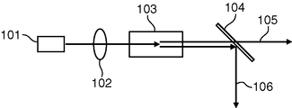
- the wavelength conversion laser includes a fundamental wave laser light source 101, a lens 102 that condenses the fundamental laser beam emitted from the laser light source 101, and a focused fundamental wave laser beam. It comprises a wavelength conversion element 103 that converts to a second harmonic, and a dichroic mirror 104 that separates the fundamental laser beam and the harmonic laser beam.
- the wavelength conversion element 103 is made of a nonlinear optical crystal and performs wavelength conversion of the fundamental wave.
- the wavelength conversion element 103 has a crystal orientation, a polarization inversion structure, and the like appropriately adjusted so that the phases of the fundamental wave and the converted wave are matched.
- a wavelength conversion element having a polarization inversion structure can perform wavelength conversion with high efficiency even at low power by quasi phase matching, and can perform various wavelength conversions by design.
- the polarization inversion structure is a structure in which a region where the spontaneous polarization of the wavelength conversion element 103 is periodically inverted is provided.
- the conversion efficiency ⁇ for converting from the fundamental wave to the second harmonic is L for the interaction length of the wavelength conversion element, P for the fundamental wave power, A for the beam cross-sectional area at the wavelength conversion element, and deviation from the phase matching condition. Assuming ⁇ k, it can be expressed as follows.
- the temperature adjusting unit is driven so that the light intensity of the converted wave converges to a target value using a detecting unit that detects the light intensity of the converted wave and a temperature adjusting unit of a nonlinear crystal. It has been proposed to control.
- Patent Document 1 does not propose controlling the intensity distribution of the converted wave light emitted from the wavelength conversion laser by controlling the wavelength conversion efficiency.
- JP-A-4-318528 JP-A-4-318528
- An object of the present invention is to provide a wavelength conversion laser capable of controlling the intensity distribution of emitted converted wave light by controlling the wavelength conversion efficiency, and an image display apparatus and a laser processing apparatus using the wavelength conversion laser. Yes.
- a wavelength conversion laser includes a fundamental wave light source that emits a fundamental wave, a wavelength conversion element that converts a fundamental wave from the fundamental wave light source into converted wave light, and the wavelength conversion element at different angles.
- a pair of fundamental wave reflecting surfaces that reflect the fundamental wave so as to define a plurality of fundamental wave optical paths that pass through the plurality of fundamental wave optical paths that are directed in different directions between the pair of fundamental wave reflecting surfaces
- a control device that controls the wavelength conversion efficiency so that the wavelength conversion efficiency in a specific fundamental wave path is the highest, and at least one of the pair of fundamental wave reflection surfaces is the converted wave light. Is an output surface that passes through.
- An image display device includes the wavelength conversion laser and a modulation element that modulates the converted wave light emitted from the wavelength conversion laser in order to display a predetermined image.
- a laser processing apparatus includes the wavelength conversion laser and a condensing optical system that condenses the converted wave light emitted from the wavelength conversion laser, and converts the converted wave light among the fundamental wave paths.
- the spot shape of the converted wave light is changed by increasing / decreasing the number of optical paths that emit light.
- the present invention it is possible to control the intensity distribution of the emitted converted wave light by controlling the wavelength conversion efficiency.
- FIG. 1 is a schematic configuration diagram of a wavelength conversion laser according to Embodiment 1 of the present invention.
- FIG. 2 is a schematic configuration diagram showing a state in which the fundamental wave path for emitting the converted wave light with priority is changed in the wavelength conversion laser of FIG.
- FIG. 3 is a schematic configuration diagram of a wavelength conversion laser according to a modification of the first embodiment of the present invention.
- FIG. 4 is a schematic configuration diagram of a wavelength conversion laser and an image display device including the wavelength conversion laser according to a modification of the first embodiment.
- FIG. 5 is a schematic configuration diagram of a wavelength conversion laser according to Embodiment 2 of the present invention.
- FIG. 6 is a schematic configuration diagram showing a state in which the fundamental wave path for emitting the converted wave light with priority is changed in the wavelength conversion laser of FIG.
- FIG. 7 is a schematic configuration diagram of a wavelength conversion laser according to the third embodiment of the present invention.
- FIG. 8 is a schematic perspective view showing the wavelength conversion element and the electrode of FIG. 7 in an enlarged manner.
- FIG. 9 is a schematic configuration diagram showing a state in which the fundamental wave optical path for emitting the converted wave light with priority is changed in the wavelength conversion laser of FIG.
- FIG. 10 is a schematic configuration diagram of a laser processing apparatus including the wavelength conversion laser according to Embodiment 3 of the present invention.
- FIG. 11 is a schematic configuration diagram of a conventional wavelength conversion laser.
- FIG. 1 and 2 are schematic configuration diagrams of a wavelength conversion laser 100 according to Embodiment 1 of the present invention.
- FIG. 1 and FIG. 2 differ from each other in that the fundamental wave optical path for emitting the converted wave light with priority is different.
- the wavelength conversion laser 100 includes a distributed feedback (hereinafter abbreviated as DFB) laser 1 as a laser light source that emits a fundamental wave, a collimator 2 that collimates the fundamental wave emitted from the DFB laser 1, and a collimated fundamental wave.
- DFB distributed feedback
- Wavelength conversion element 10 to be operated a pair of dichroic mirrors (fundamental wave reflection surfaces, output surfaces) 3 and 4 disposed so as to sandwich the wavelength conversion element 10, a beam diffuser 5 for absorbing the fundamental wave, and wavelength conversion And a control device 6 for controlling the efficiency.
- the DFB laser 1 has a grating provided in the active layer region of the LD so that a longitudinal single mode output can be easily obtained.
- the DFB laser 1 can modulate the oscillation wavelength by tuning the grating that determines the oscillation wavelength with an electric field or temperature.
- the oscillation wavelength of the DFB laser 1 can be selected from a range of 1064 to 1066 nm, and the DFB laser 1 outputs a longitudinal single mode at each wavelength.
- the wavelength conversion element 10 is made of MgO: LiTaO 3 crystal having a polarization period inversion structure, and has a rectangular parallelepiped shape. Specifically, the wavelength conversion element 10 has a polarization period reversal structure arranged in the left-right direction in FIG. 1, and generates a second harmonic as converted wave light from the fundamental wave by quasi-phase matching of the reversal period.
- the wavelength conversion element 10 has a uniform polarization inversion period within the wavelength conversion element 10 and is maintained at a constant temperature by a constant temperature holding mechanism. Further, the end face (left and right end faces in FIG. 1) where the fundamental wave of the wavelength conversion element 10 enters or exits is provided with a coat that transmits the fundamental wave and the second harmonic.
- the dichroic mirrors 3 and 4 are provided on both sides of the wavelength conversion element 10 so as to define a plurality of fundamental wave paths that pass through the wavelength conversion element 10 at different angles.
- the dichroic mirrors 3 and 4 will be described in detail.
- the dichroic mirror 3 has a coat that reflects the fundamental wave and transmits the second harmonic.
- the dichroic mirror 3 is disposed so as to be inclined in the length direction of the wavelength conversion element 10 (left-right direction in FIG. 1) from a posture perpendicular to the optical axis of the fundamental wave emitted from the DFB laser 1. Therefore, the fundamental wave reflected by the dichroic mirror 3 is incident on the wavelength conversion element 10 again along the optical axis inclined in the length direction of the wavelength conversion element 10.
- the dichroic mirror 4 also has a coat that reflects the fundamental wave and transmits the second harmonic. Further, the dichroic mirror 4 is inclined with respect to the dichroic mirror 3 at an angle that is symmetric in FIG. Therefore, the fundamental wave reflected by the dichroic mirror 4 enters the wavelength conversion element 10 again along the optical axis inclined in the length direction of the wavelength conversion element 10.
- the dichroic mirrors 3 and 4 are arranged so as to be inclined with respect to each other in this way, the fundamental wave paths A1 to A5 that gradually go upward in FIG. 1 are defined between the dichroic mirrors 3 and 4.
- the fundamental wave paths A1 to A5 are directed in different directions between the dichroic mirrors 3 and 4, respectively.
- the inclination angle with respect to the polarization inversion period of the wavelength conversion element 10 increases in the order of A1 to A5, and accordingly, the period of polarization inversion through which the fundamental wave passes increases.
- the dichroic mirrors 3 and 4 constitute an output surface for wavelength-converted light.
- the control device 6 includes an oscillation wavelength control unit 7 for controlling the wavelength of the fundamental wave oscillated from the DFB laser 1.
- the oscillation wavelength controller 7 controls the wavelength of the fundamental wave so that the wavelength conversion efficiency in a specific optical path among the fundamental wave paths A1 to A5 is maximized.
- the oscillation wavelength control unit 7 adjusts the oscillation wavelength by generating a desired electric field in the grating unit of the DFB laser 1.
- the fundamental wave emitted from the DFB laser 1 is collimated by the collimator 2 and enters the wavelength conversion element 10.
- the oscillation wavelength of the DFB laser 1 is set to 1064 nm by the oscillation wavelength control unit 7, whereby phase matching is performed in the fundamental wave path A ⁇ b> 1 that is incident perpendicular to the polarization inversion period.
- converted wave light (second harmonic) a1 is generated with the highest conversion efficiency.
- a deviation from the phase matching condition occurs due to tilting with respect to the polarization inversion structure of the wavelength conversion element 10 due to reflection of the dichroic mirrors 3 and 4, and conversion efficiency is improved.
- the converted light (second harmonics) a2 to a5 is generated only slightly. For this reason, the converted wave light a1 generated in the fundamental wave path A1 is preferentially emitted from the dichroic mirrors 3 and 4 serving as the output surface of the converted wave light. The remaining fundamental wave that has not been wavelength-converted reaches the beam diffuser 5 and is absorbed.
- the oscillation wavelength of the DFB laser 1 is set to 1066 nm by the oscillation wavelength control unit 7, so that phase matching is performed in the fundamental wave path A 5 that is most inclined with respect to the polarization inversion period.
- the second harmonic is generated with the highest conversion efficiency in the fundamental wave path A5.
- the converted wave light a5 generated in the fundamental wave path A5 is preferentially output from the dichroic mirrors 3 and 4 serving as the output surface of the converted wave light.
- a fundamental wave optical path for phase matching is selected from the fundamental wave optical paths A2, A3, A4, and is generated in each of the optical paths A2 to A4.
- the converted wave lights a2 to a4 can be emitted with priority.
- Scanning light can also be emitted using the wavelength conversion laser 100.
- the control device 6 of the wavelength conversion laser 100 modulates the oscillation wavelength of the DFB laser 1 at a constant period within a range of 1064 to 1066 nm, so that the fundamental wave path to be selected is A1 ⁇ A2 ⁇ A3 ⁇ A4 ⁇ A5 ⁇ A4 ⁇ A3 ⁇ A2 ⁇ A1 ⁇ A2... Since the emission angle of the converted wave light emitted at this time differs depending on the selected fundamental wave optical path, the converted wave light is emitted at different angles in order, and the wavelength converted light is repeatedly scanned. This scanning speed can be controlled by the modulation speed of the oscillation wavelength.
- the above-described configuration is a preferable mode in which the wavelength conversion light emitted is scanned by sequentially selecting the fundamental wave path by the control device 6. In this way, beam scanning can be performed using only the wavelength conversion laser without using a movable mirror or the like, so that the number of components and loss can be reduced.
- the converted wave light is scanned by modulating the oscillation wavelength of the fundamental wave as in the above configuration, the wavelength of the converted wave light at each scanning position is different. It can be carried out.
- various laser light sources such as a semiconductor laser, a fiber laser, and a solid-state laser can be used as the fundamental laser light source of the present invention.
- the collimator 2 used for beam shaping of the fundamental wave is used, but various optical components can be used for beam shaping of the fundamental wave to the wavelength conversion element and control of the divergence angle.
- Various nonlinear materials can be used as the wavelength conversion element. For example, LBO, KTP, LiNbO 3 or LiTaO 3 having a polarization inversion periodic structure can be used.
- two plane mirrors are used as the dichroic mirrors 3 and 4, and both of these plane mirrors are arranged to be inclined, but only one sheet may be arranged to be inclined.
- the angle at which the plane mirror is tilted is preferably at least 1 degree or more so that the optical path of the fundamental wave has a certain degree of angle change.
- both of the pair of dichroic mirrors 3 and 4 are used as output surfaces for converted wave light.
- at least one of the dichroic mirrors 3 and 4 is a surface for outputting wavelength converted light. .
- this embodiment is a preferred mode in which the oscillation wavelength control unit 7 modulates the oscillation wavelength of the fundamental wave and selects the preferred fundamental wave optical paths A1 to A5.
- the oscillation wavelength control unit 7 modulates the oscillation wavelength of the fundamental wave and selects the preferred fundamental wave optical paths A1 to A5.
- the modulation wavelength of the fundamental wave not only the angle and intensity distribution of the wavelength-converted light but also the wavelength of the emitted converted-wave light can be modulated.
- the angle change of the converted wave light to be emitted can be speeded up.
- the DFB laser 1 it is preferable to use the DFB laser 1 as in this embodiment and to use electric field modulation of the grating section. In this way, it is possible to control the oscillation wavelength at a very high speed.
- FIG. 3 is a schematic diagram of a wavelength conversion laser 100a according to a modification of the first embodiment.
- the same components as those of the wavelength conversion laser 100 are denoted by the same reference numerals and description thereof is omitted.
- the wavelength conversion laser 100a includes light receiving elements 8a, 8b, and 8c that receive a part of the converted wave lights a1, a2, and a3 emitted from the fundamental wave paths A1, A3, and A5. And a sampler 65.
- the light receiving elements 8a to 8c detect the light amount of the received converted wave light and detect which light receiving element 8a to 8c has the largest amount of incident light based on the difference between the detection values.
- the sampler 65 is an optical component that reflects part of the converted wave light emitted from the wavelength conversion element 10 and guides it to the light receiving elements 8a to 8c.
- the sampler 65 is a glass plate with a low reflection coating.
- the fundamental wave paths A1 to A5 that preferentially emit the converted wave light can be selected.
- the fundamental wave optical path from which the converted wave light is emitted with priority is detected among the fundamental wave paths A1, A3, and A5.
- the control device 6 performs feedback control so that the fundamental wave optical path detected based on the detection results of the light receiving elements 8a to 8c matches the fundamental wave optical path selected by the oscillation wavelength control unit 7. Therefore, the converted wave light is always output with priority from the selected fundamental wave optical path.
- the wavelength conversion laser 100a has a plurality of light receiving elements 8a to 8c for receiving the converted wave lights a1, a3, a5 from the fundamental wave paths A1, A3, A5, and is selected from the fundamental wave paths A1, A3, A5. This is a preferred mode capable of performing feedback control to the fundamental optical path.
- the wavelength conversion laser 100a has a plurality of fundamental wave paths A1 to A5 having different phase matching conditions, and selects an optical path using the difference in the phase matching conditions.
- the phase matching condition is affected by the surrounding environment and the elapsed time, and may change from the initial condition.
- the wavelength conversion laser 100a by performing feedback control based on the detection results of the plurality of light receiving elements 8a to 8c that detect outputs from the plurality of fundamental wave paths, the intended fundamental wave light can be obtained regardless of changes in the phase matching conditions.
- the output from the road can be prioritized.
- the configuration including the three light receiving elements 8a to 8c for receiving the converted wave lights a1, a3, and a5 from the fundamental wave paths A1, A3, and A5 has been described. However, all the fundamental wave paths A1 to A5 are provided. Five light receiving elements corresponding to A5 may be provided so that feedback control can be performed for all the fundamental wave paths A1 to A5.
- the plurality of light receiving elements includes a form in which one light receiving element is divided and used.
- Si-PD or the like can be used.
- FIG. 4 is a schematic diagram of a wavelength conversion laser 100b according to a modification of the first embodiment and an image display device 18 including the wavelength conversion laser 100b.
- the same components as those described above are denoted by the same reference numerals and description thereof is omitted.
- the wavelength conversion laser 100 b includes a DFB laser 1, a lens 2, a control device 6, and a wavelength conversion element 14.
- the DFB laser 1 outputs a fundamental wave (near 1064 nm) in a state where the oscillation wavelength can be changed by the oscillation wavelength control unit 7.
- the wavelength conversion element 14 has a trapezoidal shape (a trapezoid in which the left side in FIG. 4 is perpendicular to the upper and lower bases), and this side shape is orthogonal to the paper surface of FIG. It has a columnar outer shape extending in the direction of the movement.
- This wavelength conversion element 14 is formed with a domain-inverted structure arranged in the left-right direction in FIG.
- the wavelength conversion element 14 includes an end surface (left end surface in FIG. 4) 12 perpendicular to the fundamental wave emitted from the DFB laser 1 and an inclined end surface (right end surface in FIG. 4) 11.
- the end surface 12 has an antireflection (Anti-Reflection: AR) coat for the fundamental wave only at the incident part of the fundamental wave, and a reflection of a fundamental wave and a converted wave light (High-Reflection: HR) coat at the other part.
- the end face 11 has an HR coat for the fundamental wave and an AR coat for the converted wave light, and is an output surface for wavelength converted light. Further, the end surface 11 is inclined with respect to the end surface 12.
- the wavelength conversion element 14 is made of MgO: LiNbO 3 having a domain-inverted periodic structure, and the domain-inverted period is formed in the direction of the incident fundamental wave (left-right direction in FIG. 4).
- the fundamental wave is converted into green converted wave light (near 532 nm) by the wavelength conversion element 14. Since the end face 11 is inclined with respect to the end face 12, the optical path of the fundamental wave reflected by the end face 12 is inclined with respect to the polarization inversion period. Therefore, as the number of reflections at the end face 12 increases, the angle at which the fundamental wave path intersects the polarization inversion period increases.
- the intersection angle with the polarization inversion period increases in the order of B1 to B5. Accordingly, the phase matching conditions in the fundamental wave paths B1 to B5 differ depending on the number of reflections on the end face 12. For this reason, by modulating the wavelength of the fundamental wave by the control device 6 including the oscillation wavelength controller 7, the converted wave light can be output with priority from any one of the fundamental wave paths B1 to B5. .
- the image display device 18 includes the wavelength conversion laser 100b, the lens 15 that deflects the converted wave light from the wavelength conversion laser 100b, the light guide plate 16 that allows the converted wave light from the lens 15 to enter, and the conversion emitted from the light guide plate 16. And a liquid crystal panel 17 for displaying an image by wave light.
- the wavelength-converted light emitted from the wavelength conversion laser 100b is guided to the light guide plate 16 through the lens 15.
- the light guide plate 16 makes the beam incident from the side surface uniform, and illuminates the liquid crystal panel 17 from the back by raising the beam and emitting it from the main surface.
- the liquid crystal panel 17 displays an image by modulating the converted wave light according to the image signal.
- the liquid crystal panel 17 is a general transmissive liquid crystal panel including a polarizing plate, a liquid crystal, a TFT, and the like.
- the light guide plate 16 includes sub light guide plates 16a, 16b, and 16c. The sub light guide plates 16a, 16b, and 16c make the incident converted wave light uniform and rise to the liquid crystal panel 17 side (main surface side).
- the converted wave light b1 emitted from the fundamental wave path B1 in the wavelength conversion laser 100b is deflected by the lens 15 and enters the sub light guide plate 16a.
- the converted wave lights b3 and b5 emitted from the fundamental wave path B3 and the fundamental wave path B5 are incident on the sub light guide plate 16b and the sub light guide plate 16c, respectively. Therefore, in the wavelength conversion laser 100b, it is possible to control which part of the sub light guide plates 16a to 16c is made to emit light according to which of the fundamental wave paths B1, B3, and B5 is selected.
- the luminance distribution in the screen can be controlled by selecting the sub light guide plate to be lit among the sub light guide plates 16a to 16c. For example, when displaying a completely dark image, black is expressed without illuminating all of the sub light guide plates 16a to 16c. Further, when the number of fundamental wave optical paths that can be selected in the wavelength conversion laser 100b is large, the number of sub light guide plates can be increased accordingly.
- the image display device 18 preferably includes a modulation element that emits the converted wave light generated in the optical path selected from the fundamental wave paths B1, B3, and B5 with priority from the wavelength conversion laser 100b and modulates the converted wave light. It is a form. As described above, in the wavelength conversion laser 100b, the fundamental wave optical path for emitting the converted wave light can be selected, so that the luminance distribution of the image displayed on the image display device can be controlled.
- the portion of the liquid crystal panel 17 to be illuminated can be selected corresponding to the position of the sub light guide plates 16a to 16c.
- the sub light guide plate arranged at the position corresponding to the bright portion is used without shining the sub light guide plate arranged at the position corresponding to the black portion of the image to be displayed.
- the contrast of the image can be increased by making it shine strongly.
- power consumption can be reduced by not illuminating unnecessary areas of the light guide plate 16.
- red and blue laser light sources are used in combination with the wavelength conversion laser 100b.
- the luminance distribution of the image display device can be set for each sub light guide plate.
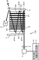
- FIG. 5 and 6 are schematic configuration diagrams of the wavelength conversion laser 200 according to Embodiment 2 of the present invention.
- FIG. 5 differs from FIG. 6 in that the fundamental wave optical path for emitting the converted wave light with priority is different.
- the wavelength conversion laser 200 includes a fiber laser 21 as a laser light source that emits a fundamental wave, a condensing lens 22 that collects the fundamental wave from the fiber laser 21, and a wavelength conversion element 20 on which the collected fundamental wave is incident. And a pair of concave mirrors 23 and 24 arranged so as to sandwich the wavelength conversion element 20, and a control device 25 for controlling the temperature of the wavelength conversion element 20.
- the fiber laser 21 emits fundamental light of linear polarization with a single mode and an output of 10 W or more. Since the conversion efficiency of the wavelength conversion element 20 is proportional to the power of the fundamental wave, a high conversion efficiency can be obtained by using the fiber laser 21, and a highly efficient wavelength conversion laser 200 can be obtained. . That is, the fiber laser 21 is a suitable fundamental wave laser light source that can make the wavelength conversion laser 200 highly efficient.
- the wavelength conversion element 20 is made of MgO: LiNbO 3 crystal having a polarization period inversion structure, and has a rectangular parallelepiped shape with a length of 25 mm, a width of 5 mm, and a thickness of 1 mm.
- the wavelength conversion element 20 has a polarization period inversion structure arranged in the left-right direction of FIG. 5 (the length direction of the wavelength conversion element 20), and is a second harmonic wave that is converted wave light by quasi-phase matching of the inversion period. Is generated.
- the stripe pattern shown in FIGS. 5 and 6 is an outline of the periodic structure, the inversion period is about 7 ⁇ m, and is substantially uniform in the wavelength conversion element 20.
- the end face (left and right end faces in FIG. 5) where the fundamental wave of the wavelength conversion element 20 enters and exits is provided with a coating that transmits the fundamental wave and the second harmonic wave (converted wave light).
- the temperature of the wavelength conversion element 20 is controlled by the temperature control unit 26 of the control device 25.
- the temperature of the wavelength conversion element 20 can be controlled by attaching a Peltier element to the bottom surface of the wavelength conversion element 20 and applying a voltage to the Peltier element by the temperature control unit 26.
- the temperature control may be performed on the entire wavelength conversion element 20 or may be performed on a part of the wavelength conversion element 20.
- the concave mirror 23 has a coat that reflects the fundamental wave and transmits the second harmonic wave, and is an output surface for emitting the second harmonic wave that is the converted wave light.
- the concave mirror 24 has a coat that reflects the fundamental wave and the second harmonic.
- the radius of curvature of the concave mirror 23 is 22 mm
- the radius of curvature of the concave mirror 24 is 20 mm
- the distance between the concave mirrors is about 21 mm in terms of air.
- the fundamental wave is reflected between the two concave mirrors 23 and 24 to reciprocate the wavelength conversion element 20 a plurality of times at different angles.
- the two concave mirrors 23 and 24 play a role of condensing the fundamental wave on the fundamental wave path in the wavelength conversion element 20. Thereby, conversion efficiency improves.
- the fundamental wave emitted from the fiber laser 21 is condensed by the condenser lens 22 so as to have a beam waist in the wavelength conversion element 20.
- the fundamental wave from the condenser lens 22 enters the wavelength conversion element 20 from the end face of the wavelength conversion element 20 that is not covered by the concave mirror 24.
- the fundamental wave emitted from the wavelength conversion element 20 is reflected by the concave mirror 23 and re-enters the wavelength conversion element 20 at a different incident angle.
- the fundamental wave radiate
- the fundamental wave reciprocates between the concave mirrors 23 and 24 and passes through the wavelength conversion element a plurality of times at different angles. That is, between the concave mirrors 23 and 24, there are a plurality of fundamental wave paths that are directed in different directions (only E1 to E7 are illustrated in FIG. 5 but more optical paths are actually defined). It is prescribed.
- the fundamental wave is condensed at a plurality of locations in the wavelength conversion element 20 in the process of reciprocation between the concave mirrors 23 and 24.
- Fundamental light is condensed and conversion efficiency is high.
- the wavelength converted light generated when the fundamental wave passes through the wavelength conversion element 20 is output from the concave mirror 23.
- the concave mirror 23 prevents the fundamental wave light from passing through the beam waist from diverging. In the collected state, the fundamental wave light is returned again to the concave mirror 24 side.
- the temperature of the wavelength conversion element 20 is controlled by the temperature control unit 26 so as to be phase-matched in the fundamental wave path that passes orthogonally to the polarization inversion periodic structure of the wavelength conversion element 20, and the temperature is maintained. Yes.
- the fundamental wave path E1 located at the bottom of FIG. 5 and the fundamental wave path E3 located above are substantially orthogonal to the polarization inversion periodic structure of the wavelength conversion element 20, these fundamental wave lights. In the paths E1 and E3, the deviation from the phase matching condition is small, the conversion efficiency is increased, and a large amount of wavelength converted light is generated.
- the wavelength conversion efficiency in the fundamental wave path E1 is the largest.
- the fundamental wave paths E2, E4, and E6 that pass through the wavelength conversion element 20 with an inclination the deviation from the phase matching condition is large, so that the conversion efficiency is low, and the generated wavelength conversion light is small. Therefore, the converted wave light generated in the fundamental wave path E1 located at the bottom of FIG. 5 and the fundamental wave path E3 located above is preferentially emitted.
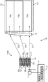
- FIG. 6 shows a state in which the temperature control unit 26 controls the temperature of the wavelength conversion element 20 to a temperature one degree lower than the example shown in FIG. 5 and this temperature is maintained.
- the deviation from the phase matching condition is small in the fundamental wave paths E5 and E7 that obliquely cross the polarization inversion periodic structure of the wavelength conversion element 20, and the conversion efficiency is high.
- the fundamental wave paths E1 and E3 substantially orthogonal to the polarization inversion periodic structure the deviation from the phase matching condition is large and the conversion efficiency is low. That is, in the example shown in FIG. 6, the converted wave light generated in the fundamental wave optical paths E5 and E7 (optical paths located in the middle stage in FIG. 6) that pass through the polarization inversion structure of the wavelength conversion element 20 is preferentially emitted. Yes. More specifically, in this embodiment, the wavelength conversion efficiency in the fundamental wave path E7 is set to be the highest.
- the temperature control unit 26 changes the temperature of the wavelength conversion element 20 so that the deviation from the phase matching condition in each of the fundamental wave paths E1 to E7 passing through the wavelength conversion element 20 at different angles. And the converted wave light generated in the specific fundamental wave path is preferentially emitted.
- the intensity distribution of the converted wave light emitted from the wavelength conversion laser 200 can be controlled by performing control so that the converted wave light generated in a specific fundamental wave path is emitted with priority.
- Embodiment 2 is a preferred embodiment in which the temperature control unit 26 controls the temperature of the wavelength conversion element 20 to generate converted wave light with priority from a specific fundamental wave path. Therefore, according to the second embodiment, it is possible to control the angle and intensity distribution of the emitted converted wave light and the number of emitted beams while keeping the wavelength emitted from the wavelength conversion laser 200 constant. Further, by performing temperature control on a part of the wavelength conversion element 20, it is possible to control the angle, the intensity distribution, and the number of beams by providing a temperature distribution in the wavelength conversion element 20.
- the converted wave light is emitted as a plurality of beams from the concave mirror 23 serving as an output surface.
- the concave mirror 23 and the concave mirror 24 are arranged to face each other so as to be coaxial, the fundamental wave incident on the wavelength conversion element 20 is reflected by the concave mirror 23 and the concave mirror. 24 is expanded in the width direction of the wavelength conversion element 20 (vertical direction in FIGS. 5 and 6) and reaches the concave mirror 23. That is, the fundamental wave travels along a plurality of fundamental wave paths (E1 to E7) existing in the width direction of the wavelength conversion element 20, and reaches the concave mirror 23 as a plurality of beams arranged in the width direction.
- the fundamental wave optical paths E 1 to E 7 that reciprocate between the concave mirrors 23 and 24 are at different angles in the width direction of the wavelength conversion element 20. Accordingly, the converted wave light emitted from the concave mirror 23 is the sum of the converted wave lights (e1, e3, e5, e7) generated in the respective fundamental wave paths (E1, E3, E5, E7). It is emitted as a horizontal multi-beam that is multi-directional in the width direction.
- the converted wave light generated in a plurality of fundamental wave paths in the fundamental wave paths (E1, E3, E5, E7) is emitted and generated in any of the fundamental wave paths.
- Preferentially emitting the converted wave light means controlling the power balance between the converted wave lights generated in the fundamental wave paths E1, E3, E5, and E7. That is, the wavelength conversion laser 200 can control the intensity distribution of the emitted lateral multi-beams by controlling the temperature of the wavelength conversion element 20.
- This embodiment is a preferred mode for controlling the intensity distribution of the converted wave light emitted by the transverse multi-beam. Since the wavelength conversion laser 200 according to the present embodiment has a plurality of fundamental wave paths, the converted wave light can be output as a plurality of beams. These multiple beams can be handled as a single light beam by forming a linear transverse multi-beam.
- being able to control the intensity distribution of the transverse multi-beam is an advantage of applying the wavelength conversion laser 200 to various application products. This is particularly effective in the field of video and lighting because it is necessary to make the intensity uniform.
- the conversion efficiency is controlled.
- the intensity of each beam included in the multi-beam can be easily controlled.
- the intensity distribution of the transverse multi-beam can be temporally changed, so that interference noise can be reduced. it can.
- the converted wave light generated in the fundamental wave paths E2 to E7 that pass through the wavelength conversion element thereafter increases more than the fundamental wave path E1 where the fundamental wave first enters the wavelength conversion element.
- the temperature of the wavelength conversion element 20 is controlled by the temperature control unit 26. In this way, the destruction of the wavelength conversion element 20 due to heat generation can be suppressed. The reason is as follows.
- the wavelength conversion laser 200 is configured to reciprocate the fundamental wave between the concave mirrors 23 and 24. Therefore, the fundamental wave has a loss during reflection at the concave mirrors 23 and 24, and Due to the consumption when the converted wave light is generated, it attenuates as the number of round trips increases. For this reason, in the fundamental wave optical path E1 which first enters the wavelength conversion element 20, the risk of heat generation and destruction of the wavelength conversion element 20 is highest. On the other hand, as shown in FIG.
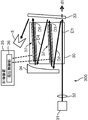
- FIG. 7 to 9 are schematic configuration diagrams of the wavelength conversion laser 300 according to Embodiment 3 of the present invention.
- FIG. 7 and FIG. 9 are different from each other in that the fundamental wave path for emitting the converted wave light with priority is different.
- the wavelength conversion laser 300 includes a mode-locked laser 31 as a laser light source that pulsates a fundamental wave, a condensing lens 32 that condenses the fundamental wave from the mode-locked laser 31, and a wavelength at which the collected fundamental wave is incident.
- Conversion element 30, dichroic mirror 33 and concave mirror 34 disposed so as to sandwich wavelength conversion element 30, electrode 37 attached to wavelength conversion element 30, and voltage applied to wavelength conversion element 30 are controlled. And a control device 35.
- the mode-locked laser 31 performs laser oscillation with a pulse width of 40 psec.
- the wavelength conversion element 30 is made of MgO: LiNbO 3 crystal having a polarization period inversion structure, and has a length of 20 mm. Further, the wavelength conversion element 30 has a polarization period reversal structure arranged in the left-right direction (the length direction of the wavelength conversion element) in FIG. 7, and generates a second harmonic that is converted wave light by quasi-phase matching of the reversal period. .
- the inversion period of the polarization period inversion structure is uniform in the wavelength conversion element 30. Further, the end face (the left and right end faces in FIG. 7) where the fundamental wave of the wavelength conversion element 30 enters and exits is provided with a coat that transmits the fundamental wave and the second harmonic.
- the temperature of the wavelength conversion element 30 is kept constant by a constant temperature holding unit (not shown).
- the dichroic mirror 33 has a coat that reflects the fundamental wave and transmits the second harmonic wave, and serves as an output surface for emitting the second harmonic wave that is the converted wave light.
- the dichroic mirror 33 is inclined from the posture perpendicular to the optical axis of the fundamental wave emitted from the mode-locked laser 31 in the length direction of the wavelength conversion element 30 (left-right direction in FIG. 7). Therefore, the fundamental wave reflected by the dichroic mirror 33 enters the wavelength conversion element 30 again along the optical axis inclined in the length direction of the wavelength conversion element 30.
- the concave mirror 34 has a coat that reflects the fundamental wave and the second harmonic.
- the concave mirror 34 plays a role of collecting the fundamental wave. Therefore, a plurality of fundamental optical paths D1 to D5 that are directed in different directions are defined between the concave mirror 34 and the dichroic mirror 33.
- the concave mirror 34 narrows the beam diameter of the fundamental wave propagating along the optical paths D3 and D5 among these fundamental wave optical paths D1 to D5.
- the fundamental wave optical path D3 and the fundamental wave optical path D5 pass through the wavelength conversion element 30 at an angle different from that of the optical path D1.
- the electrodes 37 are comb-shaped (ladder type) electrodes provided on the front and back surfaces (the top surface and the bottom surface in FIG. 8) of the wavelength conversion element 30.
- the electrode 37 is provided on each of the + z-axis plane and the ⁇ z-axis plane in the z-axis direction of the MgO: LiNbO 3 crystal. More specifically, the electrodes 37 are provided at a total of four locations so as to sandwich the two regions where the fundamental wave path D3 and the fundamental wave path D5 are defined.
- a plurality of portions extending in the width direction (the vertical direction in FIG. 7) of the wavelength conversion element 30 in each electrode 37 is formed corresponding to the period of polarization inversion of the wavelength conversion element 30.
- the control device 35 includes a voltage control unit 36 for controlling the voltage applied between the electrodes 37.
- the voltage control unit 36 applies a voltage between the pair of electrodes 37 disposed so as to sandwich the fundamental wave optical path D3 or between the pair of electrodes 37 disposed so as to sandwich the fundamental wave optical path D5.
- An electric field is generated in a partial region of the wavelength conversion element 30 in which the wave optical path D3 or the fundamental wave optical path D5 is defined.
- the electric field generated in the region of the wavelength conversion element 30 in which the fundamental wave path D3 or the fundamental wave path D5 is defined can be switched. .
- the refractive index of the wavelength conversion element 30 changes in the region where the fundamental wave path D3 and the fundamental wave path D5 are defined.
- the pulse light of the fundamental wave emitted from the mode-locked laser 31 is condensed by the condenser lens 32 and enters the wavelength conversion element 30.
- phase matching is performed in the fundamental wave optical path D1 incident perpendicularly to the polarization inversion period, and the second harmonic is generated in the fundamental wave optical path D1 with high conversion efficiency.
- the fundamental wave is incident on the wavelength conversion element 30 with an inclination, and passes through the wavelength conversion element 30 with an inclination with respect to the domain-inverted periodic structure.
- difference from phase matching conditions arises, conversion efficiency becomes low, and a 2nd harmonic is hardly generated. Therefore, only the converted wave light d1 generated in the fundamental wave path D1 is output from the dichroic mirror 33.
- the pulse width of the converted wave light d1 is about 40 psec.
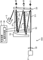
- an electric field is generated in the region of the wavelength conversion element 30 in which the fundamental wave path D3 and the fundamental wave path D5 are defined by applying a voltage to each electrode 37 by the voltage controller 36.
- the difference in refractive index between the second harmonic and the fundamental wave in the fundamental wave path of the wavelength conversion element 30 is reduced, and even if the optical path is inclined with respect to the domain-inverted periodic structure, the deviation from the phase matching condition is reduced. Get smaller. Therefore, the conversion efficiency also increases in the fundamental wave path D3 and the fundamental wave path D5 of the fundamental wave path.
- the second harmonic is generated not only in the fundamental wave path D 1 but also in the fundamental wave path D 3 and the fundamental wave path D 5, and is output from the dichroic mirror 33.
- the pulse time width of the total output of the fundamental wave optical path D1, the fundamental wave optical path D3, and the fundamental wave optical path D5 is about 100 psec.
- the output light in the fundamental wave path D3 is temporally delayed with respect to the output light in the fundamental wave path D1
- the output light in the fundamental wave path D5 is temporally delayed with respect to the output light in the fundamental wave path D3. Therefore, the pulse width of the total output light is expanded more than twice with respect to the fundamental wave from the mode-locked laser 31. Note that the pulse width of the total output light can be increased five times or more by further increasing the number of optical paths.
- the voltage controller 36 controls the amount of deviation from the phase matching condition by generating an electric field in the wavelength conversion element 30, and the fundamental of the fundamental wave path in which the converted wave light is generated. This is a preferred mode for selecting the wave paths D1, D3, and D5.
- the amount of deviation from the phase matching condition can be controlled by the fundamental wave paths D1, D3, D5 passing through the wavelength conversion element 30 at different angles and the electric field generated in the wavelength conversion element 30.
- Switching of the fundamental wave path can be performed at high speed by switching with an electric field.
- the selection of the fundamental optical path can be switched within the repetition period of the pulsed light.
- the wavelength conversion laser 300 preferably uses a mode-locked laser 31 that pulse-oscillates the fundamental wave, and controls the number of fundamental wave optical paths from which the converted wave light is emitted by the control device 35, thereby controlling the pulse width and interval of the emitted light.
- the pulse width of the emitted light can be increased from 40 psec to 100 psec by switching the number of fundamental wave light paths for emitting the converted wave light from 1 to 3.
- the pulse width can be increased several times.
- the fundamental wave path D1 and the fundamental wave path D5 are selected (in the case of FIG. 9)
- this embodiment mode it is possible to emit with a pulse width and a pulse interval that are difficult to achieve with other lasers.
- FIG. 10 shows a schematic diagram of a laser processing apparatus 39 according to a modification of the third embodiment.
- the laser processing apparatus 39 includes the wavelength conversion laser 300 and a lens 38 that condenses the converted wave light from the wavelength conversion laser 300.
- the control device 36 selects only the fundamental wave path D1 and outputs the converted wave light d1, and the wavelength conversion laser 300 outputs the converted wave lights d1, d3, and d5 from the fundamental wave paths D1 to D3. Switching is possible.
- the lens 38 condenses the converted wave light from the wavelength conversion laser 300.
- the surface of the processing object T is disposed near the condensing position of the lens 38.
- the laser processing device 39 can switch between a state in which only the converted wave light d1 is output and a state in which the converted wave lights d1 to d3 are output. A case where the beam is irradiated at one spot and a case where the beam is irradiated at three spots arranged in a line can be selected.
- the laser processing apparatus 39 can change the irradiation range (spot shape) of the beam to the workpiece T by selecting the fundamental wave path of the wavelength conversion laser 300.
- the beam irradiation range can be set in accordance with the type of processing, and the processing time can be shortened and the processing accuracy can be improved.
- the laser processing apparatus 39 according to the present embodiment can change the beam irradiation range without using a mechanical mechanism, and thus has high reliability.
- the fundamental wave optical paths D1 to D3 for preferentially emitting the converted wave light can be continuously changed in time, so that the spot shape change during beam emission or intermediate A spot shape can be created. For this reason, complicated processing can be performed quickly.
- the above-described embodiment is not limited to the above-described embodiment, and can be appropriately changed without departing from the gist of the present invention.
- the embodiments of the present invention may be used in combination.
- a plurality of fundamental wave light sources may be used, or a converted wave such as a difference frequency or a sum frequency may be output in addition to the second harmonic.
- the polarization inversion period in the wavelength conversion element may have several kinds of periods.
- the fundamental wave is reflected between a pair of fundamental wave reflection surfaces, passes through the wavelength conversion element a plurality of times at different angles, and at least one reflection surface serves as an output surface that transmits the wavelength-converted light,
- the control apparatus has a control device that performs control so that the converted wave light of a specific fundamental wave path is preferentially emitted.
- a plurality of phase matching conditions are provided by having fundamental wave paths having different angles in one wavelength conversion element.
- the conversion efficiency in the particular fundamental wave optical path is increased.
- the fundamental wave optical path other than the specific fundamental wave optical path is out of the phase matching condition, the conversion efficiency is lowered.
- the converted wave light of the specific fundamental wave optical path is emitted with priority.
- a wavelength conversion laser includes a fundamental wave light source that emits a fundamental wave, a wavelength conversion element that converts a fundamental wave from the fundamental wave light source into converted wave light, and the wavelength conversion element at different angles.
- a pair of fundamental wave reflecting surfaces that reflect the fundamental wave so as to define a plurality of fundamental wave optical paths that pass through the plurality of fundamental wave optical paths that are directed in different directions between the pair of fundamental wave reflecting surfaces
- a control device that controls the wavelength conversion efficiency so that the wavelength conversion efficiency in a specific fundamental wave path is the highest, and at least one of the pair of fundamental wave reflection surfaces is the converted wave light. Is an output surface that passes through.
- the wavelength conversion efficiency can be controlled by the control device so that the wavelength conversion efficiency in the specific optical path among the fundamental wave paths is the highest, the direction (angle) corresponding to the fundamental wave path The converted wave light can be emitted with priority.
- the present invention it is possible to provide a wavelength conversion laser capable of controlling the angle, intensity distribution, and pulse time width of the outgoing converted wave light.
- the pair of fundamental wave reflecting surfaces according to the present invention may reflect the fundamental light and at least one of the pair of fundamental wave reflecting surfaces may be a surface that causes an angle change in the optical path of the fundamental light.
- the fundamental wave reflection surface may be a convex or concave shape instead of a flat surface, and the end face of the wavelength conversion element may be the fundamental wave reflection surface.
- the shape of the reflecting surface may be a spherical surface, an aspherical surface, or a cylindrical surface.
- control device includes a temperature control unit that controls the temperature of the wavelength conversion element, and the temperature control unit selects the specific fundamental wave path by controlling the temperature of the wavelength conversion element. It can be.
- the wavelength conversion efficiency in each fundamental wave optical path can be controlled by changing the phase matching condition of the wavelength conversion element by controlling the temperature of the wavelength conversion element.
- control device includes an oscillation wavelength control unit that controls an oscillation wavelength of the fundamental wave by the fundamental wave light source, and the oscillation wavelength control unit controls the specific fundamental wave by controlling the oscillation wavelength of the fundamental wave. It can also be set as the structure which selects a wave optical path.
- the wavelength conversion efficiency in a plurality of fundamental wave paths can be controlled by changing the oscillation wavelength of the fundamental wave from the fundamental wave light source.
- control device includes a voltage control unit that applies a voltage to the wavelength conversion element in order to generate an electric field in the wavelength conversion element, and the voltage control unit generates an electric field in the wavelength conversion element.
- the specific fundamental wave path may be selected.
- the wavelength conversion efficiency in a plurality of fundamental wave paths can be controlled.
- the wavelength conversion laser further includes a light receiving element capable of detecting a light amount of the converted wave light emitted from at least one of the fundamental wave optical paths, and the control device is configured to perform the control based on the light amount detected by the light receiving element. It is preferable to control the wavelength conversion efficiency so that the wavelength conversion efficiency in the specific fundamental wave path is maximized.
- control device simultaneously emits the converted wave light generated in at least two or more of the fundamental wave paths as a multi-beam and controls the intensity distribution of the multi-beam.
- the intensity distribution of the multi-beam can be controlled by controlling the wavelength conversion efficiency in each optical path.
- the fundamental wave light source pulse-oscillates the fundamental wave
- the control device increases or decreases the number of optical paths for emitting the converted wave light among the fundamental wave optical paths. It is preferable to control at least one of the pulse width and interval of the converted wave light emitted from.
- the pulse width and interval of the converted wave light emitted from the output surface can be controlled by increasing or decreasing the number of fundamental wave light paths for emitting the converted wave light using the difference in optical path length.
- the control unit controls the wavelength conversion efficiency so that the wavelength conversion efficiency in the optical path through which the fundamental wave passes is higher than the optical path through which the fundamental wave first passes among the fundamental wave optical paths. Is preferred.
- the reason is as follows.
- the fundamental wave path where the fundamental wave first passes the power of the fundamental wave is large. Therefore, if the wavelength conversion efficiency in this fundamental wave path is increased, the power of the converted wave light also increases, and the wavelength conversion associated with the absorption of this converted wave light. The amount of heat generated by the element is large.
- the fundamental wave power after passing through the first fundamental wave path becomes small as much as the wavelength conversion is performed as in the above configuration, the wavelength conversion efficiency in the subsequent fundamental wave path is reduced. Even if it is increased, the power of the converted wave light generated thereby is small, and the heat generation amount of the wavelength conversion element is also small. Therefore, destruction of the wavelength conversion element can be suppressed.
- control device sequentially switches a fundamental wave optical path for emitting the converted wave light so that the converted wave light emitted from the output surface scans a predetermined range.
- An image display device includes the wavelength conversion laser and a modulation element that modulates the converted wave light emitted from the wavelength conversion laser in order to display a predetermined image.
- the converted wave light emitted in a specific direction from the wavelength conversion laser can be used to guide the converted wave light to an appropriate position of the modulation element according to the displayed image, so that the contrast of the image is improved.
- power consumption can be reduced.
- a laser processing apparatus includes the wavelength conversion laser and a condensing optical system that condenses the converted wave light emitted from the wavelength conversion laser, and converts the converted wave light among the fundamental wave paths.
- the spot shape of the converted wave light is changed by increasing / decreasing the number of optical paths that emit light.
- the machining time can be shortened and the machining accuracy can be improved by changing the spot shape of the converted wave light according to the type of machining.
- the present invention can be used for a wavelength conversion laser that performs wavelength conversion of a fundamental wave from a fundamental wave light source.
Landscapes
- Physics & Mathematics (AREA)
- Nonlinear Science (AREA)
- Optics & Photonics (AREA)
- General Physics & Mathematics (AREA)
- Engineering & Computer Science (AREA)
- Multimedia (AREA)
- Signal Processing (AREA)
- Optical Modulation, Optical Deflection, Nonlinear Optics, Optical Demodulation, Optical Logic Elements (AREA)
- Lasers (AREA)
Abstract
Priority Applications (4)
| Application Number | Priority Date | Filing Date | Title |
|---|---|---|---|
| CN200980000182XA CN101689007B (zh) | 2008-01-21 | 2009-01-20 | 波长转换激光器、图像显示装置以及激光加工装置 |
| EP09704279.0A EP2246735B1 (fr) | 2008-01-21 | 2009-01-20 | Laser à conversion de longueur d'onde, dispositif d'affichage d'image et appareil de traitement laser |
| US12/532,213 US8014429B2 (en) | 2008-01-21 | 2009-01-20 | Wavelength conversion laser, image display device and laser processing device |
| JP2009550462A JP5450101B2 (ja) | 2008-01-21 | 2009-01-20 | 波長変換レーザ、画像表示装置、及びレーザ加工装置 |
Applications Claiming Priority (2)
| Application Number | Priority Date | Filing Date | Title |
|---|---|---|---|
| JP2008-010876 | 2008-01-21 | ||
| JP2008010876 | 2008-01-21 |
Publications (2)
| Publication Number | Publication Date |
|---|---|
| WO2009093439A1 true WO2009093439A1 (fr) | 2009-07-30 |
| WO2009093439A9 WO2009093439A9 (fr) | 2009-12-03 |
Family
ID=40900951
Family Applications (1)
| Application Number | Title | Priority Date | Filing Date |
|---|---|---|---|
| PCT/JP2009/000176 WO2009093439A1 (fr) | 2008-01-21 | 2009-01-20 | Laser à conversion de longueur d'onde, dispositif d'affichage d'image et appareil de traitement laser |
Country Status (5)
| Country | Link |
|---|---|
| US (1) | US8014429B2 (fr) |
| EP (1) | EP2246735B1 (fr) |
| JP (1) | JP5450101B2 (fr) |
| CN (1) | CN101689007B (fr) |
| WO (1) | WO2009093439A1 (fr) |
Cited By (3)
| Publication number | Priority date | Publication date | Assignee | Title |
|---|---|---|---|---|
| JP2011059341A (ja) * | 2009-09-09 | 2011-03-24 | Nippon Telegr & Teleph Corp <Ntt> | 光偏向器 |
| JP2013161024A (ja) * | 2012-02-08 | 2013-08-19 | Advantest Corp | 波長変換装置、光源装置、および波長変換方法 |
| JPWO2019012806A1 (ja) * | 2017-07-12 | 2020-05-07 | ソニー株式会社 | 画像表示装置 |
Families Citing this family (7)
| Publication number | Priority date | Publication date | Assignee | Title |
|---|---|---|---|---|
| JP4991834B2 (ja) * | 2009-12-17 | 2012-08-01 | シャープ株式会社 | 車両用前照灯 |
| JP5232815B2 (ja) * | 2010-02-10 | 2013-07-10 | シャープ株式会社 | 車両用前照灯 |
| CN102313166B (zh) * | 2010-05-17 | 2015-01-14 | 夏普株式会社 | 发光体、发光装置、照明装置以及车辆用前照灯 |
| US8733996B2 (en) | 2010-05-17 | 2014-05-27 | Sharp Kabushiki Kaisha | Light emitting device, illuminating device, and vehicle headlamp |
| US9816677B2 (en) | 2010-10-29 | 2017-11-14 | Sharp Kabushiki Kaisha | Light emitting device, vehicle headlamp, illumination device, and laser element |
| CN103684579A (zh) * | 2013-12-04 | 2014-03-26 | 国网安徽省电力公司信息通信分公司 | 带有波段转换功能的光路保护仪及控制方法 |
| JP6698453B2 (ja) * | 2016-07-13 | 2020-05-27 | 株式会社ディスコ | 波長変換装置 |
Citations (2)
| Publication number | Priority date | Publication date | Assignee | Title |
|---|---|---|---|---|
| JPH04318528A (ja) | 1991-04-17 | 1992-11-10 | Fuji Photo Film Co Ltd | 光波長変換装置 |
| JPH05314334A (ja) * | 1992-05-08 | 1993-11-26 | Railway Technical Res Inst | 非接触式自動改札装置 |
Family Cites Families (18)
| Publication number | Priority date | Publication date | Assignee | Title |
|---|---|---|---|---|
| US5377291A (en) * | 1989-01-13 | 1994-12-27 | Kabushiki Kaisha Toshiba | Wavelength converting optical device |
| JPH03148888A (ja) * | 1989-11-06 | 1991-06-25 | Toshiba Corp | 高調波発生装置 |
| US5047668A (en) * | 1990-06-26 | 1991-09-10 | Cornell Research Foundation, Inc. | Optical walkoff compensation in critically phase-matched three-wave frequency conversion systems |
| JPH05341334A (ja) | 1992-04-10 | 1993-12-24 | Mitsubishi Electric Corp | 波長変換装置 |
| JP3052651B2 (ja) * | 1992-06-17 | 2000-06-19 | 松下電器産業株式会社 | 短波長光源 |
| US5321718A (en) * | 1993-01-28 | 1994-06-14 | Sdl, Inc. | Frequency converted laser diode and lens system therefor |
| JP2892938B2 (ja) * | 1994-06-20 | 1999-05-17 | インターナショナル・ビジネス・マシーンズ・コーポレイション | 波長変換装置 |
| JP2000357833A (ja) * | 1999-06-16 | 2000-12-26 | Shimadzu Corp | 波長変換レーザ装置 |
| DE10063977A1 (de) * | 2000-12-14 | 2002-07-25 | Eckhard Zanger | Optischer resonanter Frequenzwandler |
| US6671297B2 (en) * | 2001-04-26 | 2003-12-30 | Matsushita Electric Industrial Co., Ltd. | Wavelength conversion device |
| JP2003121895A (ja) * | 2001-10-10 | 2003-04-23 | Sumitomo Heavy Ind Ltd | 高調波発生装置、レーザアニール装置及び高調波発生方法 |
| CN1886696A (zh) * | 2003-12-22 | 2006-12-27 | 松下电器产业株式会社 | 二维图像显示装置 |
| US7356056B2 (en) * | 2004-02-27 | 2008-04-08 | Matsushita Electric Industrial Co., Ltd. | Coherent light source and control method thereof, and display unit and laser display using them |
| JP2006145584A (ja) * | 2004-11-16 | 2006-06-08 | Hitachi Via Mechanics Ltd | 波長が紫外域の複数のレーザの形成方法および形成装置並びにレーザ加工装置 |
| US7301981B2 (en) * | 2004-12-09 | 2007-11-27 | Electro Scientific Industries, Inc. | Methods for synchronized pulse shape tailoring |
| JP4883503B2 (ja) * | 2005-06-21 | 2012-02-22 | 独立行政法人情報通信研究機構 | 多重光路の固体スラブレーザロッドまたは非線形光学結晶を用いたレーザ装置 |
| JP4910643B2 (ja) * | 2005-11-11 | 2012-04-04 | パナソニック株式会社 | 表示装置 |
| US7612934B2 (en) * | 2007-12-13 | 2009-11-03 | Photodigm Inc. | Nonresonant multiple pass nonlinear structure |
-
2009
- 2009-01-20 JP JP2009550462A patent/JP5450101B2/ja not_active Expired - Fee Related
- 2009-01-20 EP EP09704279.0A patent/EP2246735B1/fr not_active Not-in-force
- 2009-01-20 US US12/532,213 patent/US8014429B2/en not_active Expired - Fee Related
- 2009-01-20 WO PCT/JP2009/000176 patent/WO2009093439A1/fr active Application Filing
- 2009-01-20 CN CN200980000182XA patent/CN101689007B/zh not_active Expired - Fee Related
Patent Citations (2)
| Publication number | Priority date | Publication date | Assignee | Title |
|---|---|---|---|---|
| JPH04318528A (ja) | 1991-04-17 | 1992-11-10 | Fuji Photo Film Co Ltd | 光波長変換装置 |
| JPH05314334A (ja) * | 1992-05-08 | 1993-11-26 | Railway Technical Res Inst | 非接触式自動改札装置 |
Cited By (5)
| Publication number | Priority date | Publication date | Assignee | Title |
|---|---|---|---|---|
| JP2011059341A (ja) * | 2009-09-09 | 2011-03-24 | Nippon Telegr & Teleph Corp <Ntt> | 光偏向器 |
| JP2013161024A (ja) * | 2012-02-08 | 2013-08-19 | Advantest Corp | 波長変換装置、光源装置、および波長変換方法 |
| JPWO2019012806A1 (ja) * | 2017-07-12 | 2020-05-07 | ソニー株式会社 | 画像表示装置 |
| JP7302472B2 (ja) | 2017-07-12 | 2023-07-04 | ソニーグループ株式会社 | 画像表示装置 |
| US11693305B2 (en) | 2017-07-12 | 2023-07-04 | Sony Corporation | Image display apparatus |
Also Published As
| Publication number | Publication date |
|---|---|
| US20100103966A1 (en) | 2010-04-29 |
| EP2246735A1 (fr) | 2010-11-03 |
| CN101689007B (zh) | 2012-11-28 |
| EP2246735B1 (fr) | 2017-11-08 |
| JP5450101B2 (ja) | 2014-03-26 |
| CN101689007A (zh) | 2010-03-31 |
| EP2246735A4 (fr) | 2012-05-16 |
| WO2009093439A9 (fr) | 2009-12-03 |
| US8014429B2 (en) | 2011-09-06 |
| JPWO2009093439A1 (ja) | 2011-05-26 |
Similar Documents
| Publication | Publication Date | Title |
|---|---|---|
| JP5450101B2 (ja) | 波長変換レーザ、画像表示装置、及びレーザ加工装置 | |
| JP5904502B2 (ja) | スペックルおよび画像フリッカを低減する走査型レーザプロジェクタの動作方法 | |
| US8270440B2 (en) | Laser light source and optical device | |
| JP4636315B2 (ja) | 1次元照明装置及び画像生成装置 | |
| JP5295969B2 (ja) | 波長変換レーザ装置およびこれを用いた画像表示装置 | |
| US7296897B2 (en) | Projection display apparatus, system, and method | |
| US7970028B2 (en) | System and methods for speckle reduction | |
| JP5096379B2 (ja) | 固体レーザー装置、表示装置及び波長変換素子 | |
| JP4729269B2 (ja) | レーザ走査型顕微鏡 | |
| JP5113668B2 (ja) | レーザ装置 | |
| JP2013533502A (ja) | 拡散性表面を用いてスペックルを低減するためのシステム及び方法 | |
| US8199396B2 (en) | Laser light source, and image display apparatus and processing apparatus using the same | |
| WO2006137326A1 (fr) | Dispositif d’affichage d’image en deux dimensions, source lumineuse d’éclairage, et dispositif d’éclairage d’exposition | |
| JP2008109083A (ja) | レーザ光源装置、照明装置、モニタ装置およびプロジェクタ | |
| KR101206031B1 (ko) | 변조 가능한 외부 공진기형 면발광 레이저 및 이를 채용한디스플레이 장치 | |
| US20140063808A1 (en) | Laser lighting device | |
| US8294979B2 (en) | Wavelength conversion device and image display apparatus using the same | |
| US8259385B2 (en) | Methods for controlling wavelength-converted light sources to reduce speckle | |
| JP5262231B2 (ja) | 光源装置及び画像表示装置 | |
| US7375868B2 (en) | Image scanning apparatus | |
| JP2009259854A (ja) | 固体レーザー装置およびこれを用いた画像表示装置 | |
| JP2008191441A (ja) | 波長変換素子、光源装置、画像表示装置、モニタ装置 | |
| WO2009081913A1 (fr) | Dispositif de sources de lumière | |
| JP2008175868A (ja) | 光源装置、照明装置、モニタ装置、画像表示装置及びプロジェクタ |
Legal Events
| Date | Code | Title | Description |
|---|---|---|---|
| WWE | Wipo information: entry into national phase |
Ref document number: 200980000182.X Country of ref document: CN |
|
| WWE | Wipo information: entry into national phase |
Ref document number: 2009550462 Country of ref document: JP |
|
| REEP | Request for entry into the european phase |
Ref document number: 2009704279 Country of ref document: EP |
|
| WWE | Wipo information: entry into national phase |
Ref document number: 12532213 Country of ref document: US Ref document number: 2009704279 Country of ref document: EP |
|
| 121 | Ep: the epo has been informed by wipo that ep was designated in this application |
Ref document number: 09704279 Country of ref document: EP Kind code of ref document: A1 |
|
| NENP | Non-entry into the national phase |
Ref country code: DE |