WO2009093300A1 - Dispositif médical et endoscope - Google Patents
Dispositif médical et endoscope Download PDFInfo
- Publication number
- WO2009093300A1 WO2009093300A1 PCT/JP2008/050701 JP2008050701W WO2009093300A1 WO 2009093300 A1 WO2009093300 A1 WO 2009093300A1 JP 2008050701 W JP2008050701 W JP 2008050701W WO 2009093300 A1 WO2009093300 A1 WO 2009093300A1
- Authority
- WO
- WIPO (PCT)
- Prior art keywords
- endoscope
- connector
- wire
- locking
- connector receiving
- Prior art date
Links
Images


Classifications
-
- A—HUMAN NECESSITIES
- A61—MEDICAL OR VETERINARY SCIENCE; HYGIENE
- A61B—DIAGNOSIS; SURGERY; IDENTIFICATION
- A61B1/00—Instruments for performing medical examinations of the interior of cavities or tubes of the body by visual or photographical inspection, e.g. endoscopes; Illuminating arrangements therefor
- A61B1/06—Instruments for performing medical examinations of the interior of cavities or tubes of the body by visual or photographical inspection, e.g. endoscopes; Illuminating arrangements therefor with illuminating arrangements
- A61B1/07—Instruments for performing medical examinations of the interior of cavities or tubes of the body by visual or photographical inspection, e.g. endoscopes; Illuminating arrangements therefor with illuminating arrangements using light-conductive means, e.g. optical fibres
-
- A—HUMAN NECESSITIES
- A61—MEDICAL OR VETERINARY SCIENCE; HYGIENE
- A61B—DIAGNOSIS; SURGERY; IDENTIFICATION
- A61B1/00—Instruments for performing medical examinations of the interior of cavities or tubes of the body by visual or photographical inspection, e.g. endoscopes; Illuminating arrangements therefor
- A61B1/00002—Operational features of endoscopes
- A61B1/00062—Operational features of endoscopes provided with means for preventing overuse
-
- A—HUMAN NECESSITIES
- A61—MEDICAL OR VETERINARY SCIENCE; HYGIENE
- A61B—DIAGNOSIS; SURGERY; IDENTIFICATION
- A61B1/00—Instruments for performing medical examinations of the interior of cavities or tubes of the body by visual or photographical inspection, e.g. endoscopes; Illuminating arrangements therefor
- A61B1/00064—Constructional details of the endoscope body
- A61B1/00103—Constructional details of the endoscope body designed for single use
-
- A—HUMAN NECESSITIES
- A61—MEDICAL OR VETERINARY SCIENCE; HYGIENE
- A61B—DIAGNOSIS; SURGERY; IDENTIFICATION
- A61B1/00—Instruments for performing medical examinations of the interior of cavities or tubes of the body by visual or photographical inspection, e.g. endoscopes; Illuminating arrangements therefor
- A61B1/00064—Constructional details of the endoscope body
- A61B1/00105—Constructional details of the endoscope body characterised by modular construction
-
- A—HUMAN NECESSITIES
- A61—MEDICAL OR VETERINARY SCIENCE; HYGIENE
- A61B—DIAGNOSIS; SURGERY; IDENTIFICATION
- A61B1/00—Instruments for performing medical examinations of the interior of cavities or tubes of the body by visual or photographical inspection, e.g. endoscopes; Illuminating arrangements therefor
- A61B1/00112—Connection or coupling means
- A61B1/00117—Optical cables in or with an endoscope
-
- A—HUMAN NECESSITIES
- A61—MEDICAL OR VETERINARY SCIENCE; HYGIENE
- A61B—DIAGNOSIS; SURGERY; IDENTIFICATION
- A61B1/00—Instruments for performing medical examinations of the interior of cavities or tubes of the body by visual or photographical inspection, e.g. endoscopes; Illuminating arrangements therefor
- A61B1/00112—Connection or coupling means
- A61B1/00121—Connectors, fasteners and adapters, e.g. on the endoscope handle
- A61B1/00126—Connectors, fasteners and adapters, e.g. on the endoscope handle optical, e.g. for light supply cables
-
- A—HUMAN NECESSITIES
- A61—MEDICAL OR VETERINARY SCIENCE; HYGIENE
- A61B—DIAGNOSIS; SURGERY; IDENTIFICATION
- A61B1/00—Instruments for performing medical examinations of the interior of cavities or tubes of the body by visual or photographical inspection, e.g. endoscopes; Illuminating arrangements therefor
- A61B1/00112—Connection or coupling means
- A61B1/00121—Connectors, fasteners and adapters, e.g. on the endoscope handle
- A61B1/00128—Connectors, fasteners and adapters, e.g. on the endoscope handle mechanical, e.g. for tubes or pipes
-
- A—HUMAN NECESSITIES
- A61—MEDICAL OR VETERINARY SCIENCE; HYGIENE
- A61B—DIAGNOSIS; SURGERY; IDENTIFICATION
- A61B1/00—Instruments for performing medical examinations of the interior of cavities or tubes of the body by visual or photographical inspection, e.g. endoscopes; Illuminating arrangements therefor
- A61B1/00064—Constructional details of the endoscope body
- A61B1/00071—Insertion part of the endoscope body
- A61B1/00078—Insertion part of the endoscope body with stiffening means
Definitions
- This invention relates to a medical device and a disposable endoscope.
- a disposable pipe unit can be attached to and detached from an insertion portion and an operation portion that are reused. And when removing the disposable pipe unit from the operation part to be reused, the front wall of the fitting groove of the pipe unit is broken by the annular convex part of the suction pipe on the operation part side. In this endoscope, the disposable pipe line unit is prevented from being reused in this way.
- An object of the present invention is to provide a medical device and a disposable endoscope that can more effectively prevent the reuse of a disposable medical device.
- a medical device in a first medical device, a second medical device that can be attached to and detached from the first medical device, and the first medical device.
- a locking means having a locking portion that is provided, a locked portion that is provided in the second medical device and is locked to the locking portion, and the first medical device and the second medical device.
- the connection state release means having an external force input portion to which an external force for releasing the connection state is applied, and the locking portion or the locked portion is irreversible from the second medical device.
- a desorbing means having a desorbing section that desorbs automatically.
- an endoscope according to the present invention is inserted into an endoscope main body having an insertion portion and the endoscope main body, and gives a predetermined hardness to the insertion portion.
- the locking means having a locking means and a maintaining part for maintaining the locked state with the connector receiving part after releasing the connection state between the endoscope main body and the connector receiving part. And a locking maintenance means.
- an endoscope according to the present invention includes an endoscope main body having an insertion portion, a wire that is inserted into the endoscope main body and can be removed from the endoscope main body, A locking means provided at a proximal end portion of the wire and having a locking portion that can be locked to a connector receiving portion that can be attached to and detached from the endoscope main body; and the endoscope main body and the connector receiving portion.
- a locking maintaining means provided in the locking means, having a maintaining portion for maintaining a locked state with the connector receiving portion after the connection state between the two is connected to the tip of the wire,
- an endoscope according to the present invention is provided with respect to an endoscope main body having an insertion portion, and a connector receiving portion that is provided in the endoscope main body and is detachable from the endoscope main body.
- a locking means having a locking part that can be locked and a locking means provided on the locking means, and when the connection state between the endoscope main body and the connector receiving part is released, the engagement from the endoscope main body.
- a detaching means having a detaching part for irreversibly detaching the stop part.
- FIG. 1A is a schematic diagram showing an endoscope system according to first to fourth embodiments.
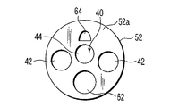
- FIG. 1B is a schematic diagram illustrating the configuration of the distal end surface of the distal end portion of the insertion portion of the endoscope of the endoscope system according to the first to fourth embodiments.
- FIG. 2A is a schematic diagram illustrating a state in which the connector of the endoscope of the endoscope system according to the first embodiment and the connector receiver of the light source device are connected.
- FIG. 2B is a schematic perspective view showing the connector of the endoscope of the endoscope system according to the first embodiment.
- FIG. 3 is a schematic longitudinal sectional view showing the structure of the flexible tube portion of the insertion portion of the endoscope of the endoscope system according to the first embodiment.
- FIG. 4A shows a claw member disposed in the connector of the endoscope of the endoscope system according to the first embodiment, and a connector, a universal cable, an operation unit, and an insertion unit fixed to the claw member. It is a schematic perspective view which shows the provided wire.
- FIG. 4B shows a claw member disposed in the connector of the endoscope of the endoscope system according to the first embodiment, and a connector, a universal cable, an operation unit, and an insertion unit fixed to the claw member. It is a schematic perspective view which shows the provided wire.
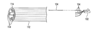
- FIG. 5 is a tube used for a flexible tube or a universal cable of an insertion portion of an endoscope of the endoscope system according to the first embodiment, and a wire fixed to a claw member is a tube of the tube. It is a schematic perspective view which shows the state inserted in a wire penetration hole.
- FIG. 6 is a schematic diagram illustrating a state in which the imaging cable side connector and the imaging cable side connector of the observation optical system of the endoscope of the endoscope system according to the second embodiment are connected.
- FIG. 7A is a schematic cross-sectional view showing a flexible tube portion of an insertion portion of an endoscope of an endoscope system according to a third embodiment.
- FIG. 7B shows an operation portion side operation wire and a distal end side operation wire of the insertion portion among the operation wires inside the endoscope insertion portion or operation portion of the endoscope system according to the third embodiment. It is the schematic which shows the state connected.
- FIG. 8A is a schematic diagram illustrating a state in which the connector of the endoscope of the endoscope system according to the fourth embodiment is connected to the connector receiving portion of the light source device.
- FIG. 8B is a schematic diagram illustrating a state immediately before the connector of the endoscope of the endoscope system according to the fourth embodiment is connected to the connector receiving portion of the light source device.
- FIG. 8C shows a state immediately before the connector of the endoscope of the endoscope system according to the fourth embodiment and the connector receiving portion of the light source device are connected, and FIG. 8B shows the endoscope shown in FIG. 8B. It is the schematic which shows the modification of a connector.
- an endoscope system (medical device) 10 includes a disposable type endoscope (first medical device) 12 and a light source device (first device) that is reused. 2 medical devices) 14, a processor 16, a solenoid valve 18, and a monitor 20.
- the light source device 14 supplies illumination light for illuminating the subject to a light guide bundle of an illumination optical system described later.
- the light source device 14 is formed with a light source device connector receiving portion 22 in which a light guide connector 92 is disposed in a connector 38 (described later) of the endoscope (endoscope main body) 12.
- the light source device connector receiving portion 22 is formed with a recess (locked portion, locking means) 22a with which a claw member 102 described later is engaged.
- the light source device connector receiving portion 22 is formed with a rod guide 22b in which a light guide rod 92a (to be described later) of the light guide connector 92 is disposed.
- a light source (not shown) is disposed behind the rod guide 22b.
- An endoscope 12, a light source device 14, an electromagnetic valve 18, and a monitor 20 are detachably connected to the processor 16 shown in FIG. 1A, and these are controlled to a desired state. That is, the processor 16 is formed with a processor connector receiving portion 24 in which an electrical connector 94 is disposed in a connector 38 to be described later of the endoscope 12. The processor 16 receives an operation of a switch 86 of the operation unit 34 (to be described later) of the endoscope 12 or automatically controls the light source device 14, the electromagnetic valve 18, the monitor 20, and the like based on the setting.
- the electromagnetic valve 18 is used for a gas such as air flowing in an air / water supply tube (not shown) or a liquid such as physiological saline. Control the flow rate. Further, the electromagnetic valve 18 controls the flow rate (suction force) at which the gas or liquid sucked through the inside of the suction tube (not shown) is sucked based on the operation of the switch 86 of the operation unit 34.
- the monitor 20 displays an image observed by an observation optical system 40 (to be described later) of the endoscope 12 and displays the state of the endoscope 12 and the like.
- the endoscope (endoscope main body) 12 includes an insertion portion 32 that is inserted into a body cavity of a subject, an operation portion 34 that is connected to a proximal end portion of the insertion portion 32, and an extension from the operation portion 34.
- the taken-out universal cable 36 and a connector (external force input part, connection state releasing means) 38 disposed distal to the operation part 34 of the universal cable 36 are provided.
- An illumination optical system and an observation optical system 40 are inserted through the insertion section 32, the operation section 34, the universal cable 36, and the connector 38.
- the illumination optical system includes an illumination lens 42 (see FIG. 1B) and a light guide bundle (not shown) disposed on the base end side of the illumination lens 42.
- the observation optical system 40 includes an objective lens unit 44 (see FIG. 1B), a solid-state imaging device (imaging unit) (not shown), and an imaging cable (not shown).
- the objective lens unit 44 forms an image of light incident on the objective lens unit 44.
- the solid-state imaging device is disposed on the proximal end side of the objective lens unit 44.
- the solid-state imaging device is, for example, a CCD or a CMOS, and captures an image formed by the objective lens unit 44 and photoelectrically converts the image into an electrical signal.
- the imaging cable transmits an electrical signal photoelectrically converted by the solid-state imaging device to the connector 38 via the universal cable 36.
- the observation optical system 40 has an eyepiece in the operation unit 34 and a structure that allows the subject to be observed with the eyepiece (the presence or absence of the monitor 20 may be either) or the objective lens unit 44 (see FIG. 1B).
- various structures such as a structure having an image guide fiber and an eyepiece (the presence or absence of the monitor 20 may be used) are allowed.
- the insertion portion 32 includes a distal end hard portion 52, a bending portion 54, and a flexible tube portion 56 from the distal end side toward the proximal end side.
- the distal end portion such as the illumination optical system, the observation optical system 40, the air / water feeding tube, and the suction tube is fixed to the distal end hard portion 52.
- the distal end surface 52a of the distal end hard portion 52 has two illumination lenses 42 of the illumination optical system, an objective lens unit 44 of the observation optical system 40, and a distal end opening 62 of the suction tube.
- An air / water nozzle 64 is disposed.
- the distal end portion of the light guide bundle (not shown) is fixed to the distal end hard portion 52 behind the illumination lens 42.
- a solid-state imaging device is fixed behind the objective lens unit 44.
- the proximal end portions of the air / water feeding tube and the suction tube are connected to the connector 38 through the bending portion 54 and the flexible tube portion 56 of the insertion portion 32, and further through the operation portion 34 and the universal cable 36. Further, the suction tube is branched to a treatment instrument insertion port 88a disposed in a bend stopper 88 (to be described later) of the operation unit 34.
- the bending portion 54 is connected to the bending operation knob 84 of the operation portion 34 with an operation wire (not shown) so as to be bent by an operation of a bending operation knob 84 (to be described later) of the operation portion 34, and is a bending tube having a plurality of bending pieces.
- the outer tube is coated on the outside.
- the flexible tube portion 56 includes a flex 72, a blade 74 disposed outside the flex 72, and an outer skin 76 disposed outside the blade 74.
- the flex 72 has a strip-shaped metal thin plate formed in a spiral shape.
- the blade 74 is knitted in a net shape and formed into a tubular shape.
- the outer skin 76 is formed of a resin material in a tube shape.
- the blade 74 is not necessarily arranged (see FIG. 7A of a third embodiment described later).
- the flexible tube portion 56 is formed so as to have moderate flexibility, but the flexible tube portion 56 of this embodiment is more flexible than the flexible tube portion normally used in an endoscope.
- the one having a high (softly formed) is used.
- the degree of flexibility can be adjusted by appropriately setting the flexibility of the flex 72, the blade 74, and the outer skin 76. Such flexibility of the flexible tube portion 56 is determined by the balance with the wire 104 described later.
- the degree of flexibility of the flexible tube portion 56 itself is, for example, the extent that the flexible tube portion 56 is easily bent into a free shape (so-called “funyafunya”). It is preferable that it is in a state where it cannot be used.
- wires are inserted into the inside of the flex 72 through which wires (detachment portions and detachment means) 104 for adjusting the flexibility of the flexible tube portion 56 are respectively inserted.
- the hole 78 is fixed.
- These wire insertion holes 78 are fixed to the inner peripheral surface of the flex 72 at intervals of about 90 degrees with respect to the central axis of the flex 72.
- the shape of the wire insertion hole 78 can be set as appropriate, and various shapes such as a straight line shape and a spiral shape are allowed with respect to the inner peripheral surface of the flex 72.
- FIG. 3 shows an example in which the wire insertion holes 78 are fixed to the inner peripheral surface of the flex 72 in a straight line.
- the operation unit 34 includes an operation unit main body 82, a bending operation knob 84 having a stopper 84a, a switch 86, and a bend stopper 88.
- the operation section main body 82 is formed with a treatment instrument insertion port 88a connected to a suction tube disposed in the insertion section 32.
- the endoscope treatment instrument ⁇ is inserted into the suction tube from the treatment instrument insertion port 88a of the endoscope 12 and pushed into the distal end hard portion 52 side, and then is externally connected to the distal end opening 62 of the suction tube. Protruding.
- the operation section main body 82 is provided with a bending operation knob 84 and a switch 86.
- the bending operation knob 84 is operated when the bending portion 54 of the insertion portion 32 is bent.
- the switch 86 is operated when air or water is supplied to the subject or when blood or physiological saline near the subject is aspirated.
- the switch 86 is provided with a signal line (not shown) in the universal cable 36 so as to be electrically connected to the processor 16, and a distal end thereof is provided on an electrical connector 94 described later of the connector 38. Has been.
- the operation portion main body 82 is provided with a bend stop 88 of the flexible tube portion 56.
- the anti-folding 88 constitutes a grip portion that is held by the user of the endoscope 12 in cooperation with the operation portion main body 82.
- the universal cable 36 is extended from the operation unit main body 82.
- the universal cable 36 has the same structure as the flexible tube portion 56 of the insertion portion 32 shown in FIG. 3, for example.
- the universal cable 36 is also formed so as to have an appropriate flexibility like the flexible tube portion 56.
- the universal cable 36 of this embodiment is a universal cable usually used for an endoscope. Those having higher flexibility (softly formed) are used. For this reason, the degree of flexibility of the universal cable 36 itself is used as the universal cable 36 of the endoscope 12 as it is, for example, the degree that the universal cable 36 can be easily bent into a free shape (so-called Funyafunya). It is preferable that the state is not possible.
- a connector 38 is disposed at an end of the universal cable 36 on the distal side with respect to the operation unit main body 82.
- the connector 38 includes a main body 38a, a light guide connector (locking portion, locking means) 92, an electrical connector 94 disposed at an end of the cable 94a, and an air / water supply port.
- a gold 96 and a suction base 98 are provided.
- the main body 38a is formed in a substantially cylindrical shape or a substantially columnar shape.
- a light guide connector 92 is disposed at the distal end portion of the main body 38a of the connector 38 (the end portion on the side connected to the light source device connector receiving portion 22 of the light source device 14). As shown in FIGS. 2A and 2B, the light guide connector 92 includes a light guide rod 92a and a recess 92b. The light guide rod 92a is disposed to allow illumination light to enter the light guide bundle from the light source device 14. On the other hand, a claw member 102 (see FIG. 4A) to which a wire 104 described later is connected is disposed in the recess 92b.
- the cable 94a is extended from the side of the main body 38a of the connector 38.
- An electrical connector 94 is disposed at the end of the cable 94a.
- the electrical connector 94 is detachably engaged with the processor connector receiving portion 24 of the processor 16.
- an air / water supply base 96 and a suction base 98 are disposed on the side of the main body 38a of the connector 38.
- An air supply pump and a water supply pump (not shown) are detachably connected to the air supply / water supply base 96.
- a suction pump and a suction bottle (not shown) are detachably connected to the suction base 98.
- the claw member (locking portion, locking means, maintaining portion, locking maintaining means) 102 disposed in the recess 92b of the light guide connector 92 is formed in a substantially L shape.
- the claw member 102 includes a substantially rectangular parallelepiped accommodation portion 102a accommodated inside the recess 92b, and a claw portion 102b extending laterally from the accommodation portion 102a.
- the tip of the claw portion 102 b is in a state of protruding outward from the outer periphery of the light guide connector 92 when the claw member 102 is disposed in the recess 92 b of the light guide connector 92. Therefore, the claw portion 102 b of the claw member 102 is engaged with the recess 22 a of the light source device connector receiving portion 22 when the light guide connector 92 is connected to the light source device connector receiving portion 22 of the light source device 14. .
- the base end of the wire 104 having an appropriate stiffness is fixed to the accommodated portion 102a of the claw member 102.
- the wire 104 is disposed across the connector 38, the universal cable 36, the operation unit 34, and the insertion unit 32.
- the distal end of the wire 104 is disposed so as to freely move, for example, inside the distal end hard portion 52 of the insertion portion 32 or inside the bending portion 54.
- the wire 104 gives an appropriate stiffness to the universal cable 36 and the flexible tube portion 56 of the insertion portion 32. That is, the wire 104 serves to reinforce the flexible tube portion 56 and the universal cable 36.
- the flexible tube portion 56 and the universal cable 36 in this embodiment are too flexible compared to the commonly used flexible tube portion and universal cable.
- the flexibility of the flexible tube portion 56 and the universal cable 36 in a state where the wire 104 is not inserted is greatly separated from a desired level.
- the flexible tube portion 56 and the universal cable 36 into which the wire 104 is inserted are adjusted so that the flexibility is lowered due to the stiffness of the wire 104 and has a desired degree of flexibility.
- the wire 104 is made of carbon steel, stainless steel, glass fiber, plastic material, or the like, and various types such as a single wire or a stranded wire are used.
- the light guide connector 92 of the connector 38 is attached to the light source device connector receiving portion 22 of the light source device 14.
- the electrical connector 94 of the connector 38 is attached to the processor connector receiving portion 24 of the processor 16.
- an air supply pump and a water supply pump are attached to the air supply / water supply base 96, and a suction pump and a suction bottle (not shown) are attached to the suction base 98.
- the claw member 102 is engaged with the recess 22 a of the light source device connector receiving portion 22.
- the wire 104 is inserted through the universal cable 36, the operation unit 34, and the insertion unit 32. Therefore, the flexible tube portion 56 and the universal cable 36 of the insertion portion 32 of the endoscope 12 have flexibility that is easy to use.
- the insertion portion 32 of the endoscope 12 is inserted into the body cavity, and the endoscope treatment instrument ⁇ and the like are inserted from the treatment instrument insertion port 88a so as to protrude from the distal end opening 62, and the subject is thus removed. Take appropriate measures while observing.
- the light guide connector 92 of the connector 38 is removed from the light source device connector receiving portion 22 of the light source device 14.
- the light guide connector 92 of the connector 38 is separated from the light source device connector receiving portion 22 of the light source device 14, but the claw member 102 fixed to the proximal end of the wire 104 has a claw portion 102 b of the light source of the light source device 14. It continues to engage with the recess 22a of the device connector receiving portion 22 (acts as a maintaining portion or a locking maintaining means that keeps the engaged state). For this reason, the claw member 102 is left in the recess 22 a of the light source device connector receiving portion 22 of the light source device 14.
- the distal end of the wire 104 is not fixed with respect to the inside of the distal end hard portion 52 or the operation portion 34 of the endoscope 12 and is in a free state, the wire 104 fixed to the claw member 102 is not visible. Gradually removed from the mirror 12. That is, the distal end of the wire 104 reaches the flexible tube portion 56 from the distal end hard portion 52 or the operation portion 34 of the insertion portion 32.
- the tip of the wire 104 is pulled out to the operation unit 34 of the endoscope 12. Then, the elasticity 104 is given to the flexible tube portion 56 itself by inserting the wire 104 having the stiffness into the flexible tube portion 56, but as the wire 104 is pulled out, the tip of the flexible tube portion 56 is provided. The stiffness is lost from the side toward the base end. Then, once the tip of the wire 104 is pulled out to the operation portion 34, the wire 104 cannot be inserted into the wire insertion hole 78 of the flexible tube portion 56 of the insertion portion 32.
- the flexible tube portion 56 of the insertion portion 32 of the endoscope 12 becomes too soft and can be easily bent. That is, when the insertion portion 32 is to be inserted into the body cavity or the like from the distal rigid portion 52, if the distal rigid portion 52 comes into contact with the body wall or the like, the flexible tube portion 56 is easily bent and allowed. Depending on the degree of flexibility of the flexible tube portion 56 itself, the shape of the conduit inside the flexible tube portion 56 cannot be maintained.
- the endoscope 12 having the insertion portion 32 in which the flexibility of the flexible tube portion 56 is too high is poor in insertability of the insertion portion 32 into the body cavity, and the rotation of the insertion portion 32 around the axis. It is difficult to transmit the rotational force in For this reason, after the light guide connector 92 of the connector 38 of the disposable endoscope 12 is temporarily attached to and removed from the light source device 14, the light guide connector 92 of the endoscope 12 is attached to the connector receiving portion 22 of the light source device 14. Even if it is attached again, the endoscope 12 can be very difficult to use. Therefore, reuse of the endoscope 12 can be effectively prevented.
- the following can be said. After the light guide connector 92 of the connector 38 of the endoscope 12 is once attached to the light source device connector receiving portion 22 of the light source device 14, the light guide connector 92 of the connector 38 of the endoscope 12 is used for the light source device of the light source device 14.
- the wire 104 that gives stiffness to the flexible tube portion 56 and the universal cable 36 of the insertion portion 32 is also removed from the endoscope 12. For this reason, in particular, the stiffness (flexibility) of the flexible tube portion 56 of the insertion portion 32 can be weakened so as not to be suitable for use of the endoscope 12.
- the light guide connector 92 is formed with a recess 92b where one claw member 102 is disposed, and the light source device connector receiving portion 22 of the light source device 14 is engaged with the same claw member 102.
- the formation of 22a has been described.
- about two to four concave portions 92b are formed in the light guide connector 92, the same number of concave portions 22a are formed in the light source device connector receiving portion 22 of the light source device 14, and the claw member 102 shown in FIG. It is also preferable that the concave portions 92b and 22a are disposed. That is, it is also preferable that the claw member 102 is arranged in a state where one wire 104 is fixed and the distal end of the wire 104 reaches the bending portion 54 of the insertion portion 32 of the endoscope 12.
- the number of the wires 104 fixed to the claw member 102 is two or three.
- the two wires insertion holes 78 are provided on the inner peripheral surface of the flex 72, it is preferable that the two wires insertion holes 78 are provided at symmetrical positions (opposing positions), and three wire insertion holes 78 are provided. In this case, it is preferable to be arranged at intervals of 120 degrees with respect to the central axis of the flex 72, for example. It is also preferable that the number of wire insertion holes 78 is appropriately set depending on the strength of the wire 104.
- the flexible tube 56 and the universal cable 36 of the insertion portion 32 of the endoscope 12 are described as having a flex 72 (and a blade 74) and an outer skin 76 as shown in FIG. did.
- a tube 112 in which a wire insertion hole 114 is formed as shown in FIG. 5 instead of the flexible tube portion 56 and the universal cable 36.
- the tube 112 is not particularly limited as long as it has flexibility (flexibility).
- a plastic material polyethylene (PE), polypropylene (PP), polyvinyl alcohol (PVA), or the like is appropriately used. It is formed by the thing laminated
- the structure of the concave portion 92 b of the light guide connector 92 of the endoscope 12 is applied to the electric connector 94 of the endoscope 12, and the structure of the concave portion 22 a of the connector receiving portion 22 of the light source device 14 is applied to the connector connector for the processor of the processor 16. It is also preferable to apply to the part 24. It is also preferable to dispose the claw member 102 on the electric connector 94 and dispose the wire 104 on the electric connector 94, the cable 94 a, the universal cable 36, the operation unit 34, and the insertion unit 32.
- the observation optical system 40 includes an objective lens unit 44 (see FIG. 1B), a solid-state imaging device (imaging unit) 44a, and an imaging cable 44b.
- the outer peripheral surface on the distal end side of the objective lens unit 44 is disposed on the distal end hard portion 52, and the proximal end of the objective lens unit 44 is fixed to the solid-state imaging device 44a.
- An image sensor side connector (connecting portion) 46a is formed on the surface of the solid-state image sensor 44a opposite to the surface on which the objective lens unit 44 is disposed, and the image sensor side is formed at the tip of the image sensor cable 44b.
- An imaging cable side connector (connection portion) 46b that can be attached to and detached from the connector 46a is formed. In other words, detachable connectors (connection portions) 46a and 46b are disposed between the solid-state imaging device 44a and the imaging cable 44b.
- the tip of the wire (detachment section, detachment means) 104a of this embodiment instead of the wire 104 described in the first embodiment is fixed (connected) to the imaging cable side connector 46b.
- the connection between the image sensor side connector 46a and the image sensor cable side connector 46b is such that when the image sensor side connector 46a is fixed in a certain space, for example, the wire 104a is pulled out so as to be pulled out, the wire 104a is cut.
- the adjustment is made so that the connection between the image sensor side connector 46a and the image sensor cable side connector 46b is released.
- the proximal end of the wire 104a described in this embodiment is fixed to the accommodated portion 102a of the claw member 102, similarly to the wire 104 described in the first embodiment. That is, the wire 104a is disposed inside the endoscope 12 like the wire 104 described in the first embodiment.
- the wire 104a is for adjusting the flexibility of the flexible tube portion 56 and the universal cable 36 as described in the first embodiment (having an adjustment force for adjusting the flexibility). Alternatively, it may be one that does not have such an adjusting force and is simply used to connect the claw member 102 and the imaging cable side connector 46b of the observation optical system 40. Since the former has been described in the first embodiment, this embodiment will be described as being the latter.
- the operation of the endoscope system 10 will be described.
- the insertion portion 32 of the endoscope 12 is inserted into the body cavity, and the treatment instrument ⁇ for endoscope is inserted into the treatment instrument.
- An appropriate treatment is performed while observing the subject by inserting from the mouth 88a and projecting from the distal end opening 62.
- the light guide connector 92 of the connector 38 is removed from the light source device connector receiving portion 22 of the light source device 14.
- the light guide connector 92 of the connector 38 is separated from the light source device connector receiving portion 22 of the light source device 14, but the claw member 102 fixed to the proximal end of the wire 104 has a claw portion 102 b of the light source of the light source device 14.
- the claw member 102 is left in the recess 22 a of the light source device connector receiving portion 22 of the light source device 14.
- the distal end of the wire 104 is fixed to the imaging cable side connector 46b, and the imaging element side connector 46a is formed on the solid-state imaging element 44a to which the objective lens unit 44 disposed in the distal end hard portion 52 is fixed. That is, the solid-state imaging device 44 a is fixed in the vicinity of the distal end portion of the insertion portion 32 of the endoscope 12. For this reason, the farther the connector 38 of the endoscope 12 is away from the connector receiving portion 22 of the light source device 14, the more tension is applied to the wire 104a, that is, between the imaging element side connector 46a and the imaging cable side connector 46b. A force to disconnect is applied.
- the connection between the image sensor side connector 46a and the image pickup cable side connector 46b is finally released.
- the image sensor side connector 46a and the image sensor cable side connector 46b once disconnected are located inside the endoscope 12. For this reason, the imaging element side connector 46a and the imaging cable side connector 46b are not connected without disassembling the endoscope 12.
- the objective lens unit 44 is described as being fixed to the solid-state imaging device 44a.
- the objective lens unit 44 and the solid-state imaging device 44a can be attached or detached, or the imaging cable 44b itself can be attached. It is also preferable that the two can be separated in the axial direction. That is, in this embodiment, the solid-state imaging device 44a is described as having the imaging device-side connector 46a and the imaging cable 44b is formed with the imaging cable-side connector 46b. It is also preferable that it is disposed on the imaging cable 44b.
- the connectors 46a and 46b do not need to be disposed in the insertion portion 32, and are preferably disposed in the operation portion 34, the universal cable 36, or the connector 38.
- the wire 104a is more preferable because it only requires a shorter length than the case where it is disposed inside the insertion portion 32.
- similar connectors 46a and 46b are provided on signal lines and / or power supply lines (both not shown) disposed in the imaging cable 44b. That is, it is also preferable that the connectors 46a and 46b are disposed at any position of the imaging cable 44b.
- FIGS. 7A and 7B a third embodiment will be described with reference to FIGS. 7A and 7B.
- This embodiment is a modification of the first and second embodiments, and the same members or members having the same functions as those described in the first and second embodiments have the same reference numerals. The detailed description is omitted.
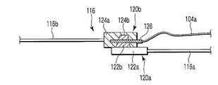
- connection portions 120 a and 120 b connect the operation portion side operation wire 116 a close to the operation portion 34 and the distal end side operation wire 116 b close to the distal end portion of the insertion portion 32 among the operation wires 116.
- a first connection portion 120a having a base portion 122a and a convex portion 122b is disposed at the distal end of the operation portion side operation wire 116a (the side close to the distal end of the insertion portion 32).
- the base 122a is fixed to the tip of the operation unit side operation wire 116a.
- the convex part 122b is formed integrally with the base part 122a.
- a second connection portion 120b having a base portion 124a and a concave portion 124b is disposed at the proximal end (the side close to the operation portion 34) of the distal end side operation wire 116b.
- the base part 124a is fixed to the base end of the distal end side operation wire 116b.
- the concave portion 124b is formed integrally with the base portion 124a and is formed so as to receive the convex portion 122b of the first connecting portion 120a.
- the cross section of the part put into the recessed part 124b of the 2nd connection part 120b among the 1st connection parts 120a is formed in the substantially trapezoid shape (the whole is a substantially truncated cone shape).
- the axial direction (center axis) of the convex portion 122 b of the first connecting portion 120 a and the concave portion 124 b of the second connecting portion 120 b is a direction orthogonal to the axial direction of the operation wire 116. For this reason, in the state which the convex part 122b of the 1st connection part 120a and the recessed part 124b of the 2nd connection part 120b were fitted, it pulls out easily.
- the pin is pinned in an appropriate direction such as parallel or substantially parallel to the axial direction of the operation wire 116, for example.
- 126 is inserted and the convex part 122b of the 1st connection part 120a and the recessed part 124b of the 2nd connection part 120b are fitted in the state penetrated.
- the pin 126 is formed in a wedge shape, and when the first connection portion 120a and the second connection portion 120b are fitted to each other so as to pass through the first connection portion 120a, the pin 126 is wedged to cause the first connection portion 120a.
- the tip of the wire 104a described in the second embodiment is connected to the pin 126.
- the proximal end of the wire 104 a is fixed to the accommodated portion 102 a of the claw member 102. Since other structures are the same as those described in the second embodiment, a detailed description thereof will be omitted.
- the insertion portion 32 of the endoscope 12 is inserted into the body cavity, and the treatment instrument ⁇ for endoscope is inserted into the treatment instrument.
- An appropriate treatment is performed while observing the subject by inserting from the mouth 88a and projecting from the distal end opening 62.
- the light guide connector 92 of the connector 38 is removed from the light source device connector receiving portion 22 of the light source device 14.
- the light guide connector 92 of the connector 38 is separated from the light source device connector receiving portion 22 of the light source device 14, but the claw member 102 fixed to the proximal end of the wire 104 a has the claw portion 102 b of the light source of the light source device 14.
- the claw member 102 is left in the recess 22 a of the light source device connector receiving portion 22 of the light source device 14.
- the tip of the wire 104a is connected to the protrusion 122b of the first connection part 120a and the second of the connection parts 120a and 120b that connect the operation part side operation wire 116a and the tip side operation wire 116b of the insertion part 32. It is fixed to the base end of the pin 126 that penetrates the recess 124b of the connecting portion 120b. For this reason, the farther the connector 38 of the endoscope 12 is from the connector receiving portion 22 of the light source device 14, the more tension is applied to the wire 104a, that is, the pin 126 has a convex portion 122b of the first connecting portion 120a. And the force extracted from the state which penetrates the recessed part 124b of the 2nd connection part 120b is applied.
- the pin 126 is removed from a state of penetrating the convex portion 122b of the first connecting portion 120a and the concave portion 124b of the second connecting portion 120b.
- the tension applied to the operation wire 116 at the time of manufacturing the endoscope 12 the operation unit 34 is operated, and the operation wire 116 is moved back and forth along the axial direction thereof.
- these forces are transmitted to the concave portion 124b and the base portion 124a of the second connection portion 120b through the base portion 122a and the convex portion 122b of the first connection portion 120a.
- the substantially frustoconical convex portion 122b of the first connecting portion 120a applies a force in a direction away from the axial direction of the operation wire 116 from the slope of the substantially frustoconical concave portion 124b of the second connecting portion 120b. receive. Accordingly, the substantially frustoconical convex portion 122b of the first connecting portion 120a slides along the slope of the substantially frustoconical concave portion 124b of the second connecting portion 120b, and the first and second connecting portions 120a. , 120b is released.
- the endoscope 12 since the space between the convex portion 122b of the first connecting portion 120a once disconnected and the concave portion 124b of the second connecting portion 120b is inside the endoscope 12, the endoscope 12 is not disassembled.
- the pin 126 cannot be disposed so as to penetrate the convex portion 122b of the first connecting portion 120a and the concave portion 124b of the second connecting portion 120b.
- the operation force operated by the operation wire 116 is not normally transmitted to the bending portion 54 through the operation wire 116. . Therefore, the bending portion 54 cannot be bent normally. That is, since the bending operation of the endoscope 12 cannot be normally used, the bending function of the endoscope 12 cannot be used. Therefore, reuse of the endoscope 12 can be effectively prevented.
- the first and second connection portions 120a and 120b may be disposed at any position as long as the operation wire 116 is disposed from the operation portion 34 to the distal end side of the insertion portion 32. Although it is good, it is preferable from the viewpoint of preventing the insertion portion 32 from being enlarged in diameter, provided in the operation portion 34 or at a position in the insertion portion 32 close to the operation portion 34.
- FIGS. 8A to 8C a fourth embodiment will be described with reference to FIGS. 8A to 8C.
- This embodiment is a modification of the first embodiment, and the same members as those described in the first embodiment or members having the same action are denoted by the same reference numerals, and detailed description will be given. Is omitted.
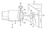
- the connector receiving portion 22 of the light source device 14 of this embodiment is different from the connector receiving portion 22 of the light source device 14 described in the first embodiment.
- a projection 132 having a locking portion 132a is provided. That is, the convex portion 132 and the flange portion 132 a form the connector receiving portion 22 that protrudes outside the light source device 14.
- the light guide connector 92 of the connector 38 of the endoscope 12 has a substantially disc-shaped recess 142 formed at the tip thereof (the end connected to the connector receiving portion 22 of the light source device 14).
- the concave portion 92b (see FIGS. 2A and 2B) described in the first embodiment of the light guide connector 92 is not formed in the light guide connector 92, and the claw member 102 and the wire 104 are not provided. Absent.
- an annular engagement portion 144 is formed at the tip of the light guide connector 92 by a substantially disc-shaped recess 142.
- the engaging portion 144 includes an inclined portion 146 that is inclined from the outside to the inside of the light guide connector 92.
- the inclination direction of the inclined portion 146 is higher toward the outer side and lower toward the inner side.
- the engaging portion 144 of the concave portion 142 is formed of a resin material only in an area of the annular engaging portion 144 that slightly exceeds 180 degrees, for example, and the remaining portion (area) is made of a hard material (for example, stainless steel). Steel).
- the engaging portion 144 includes a soft portion (locking portion, locking means, detaching portion, detaching means) 144a and a hard portion 144b.
- the inclined portion 146 of the light guide connector 92 is connected to the flange portion 132 a of the connector receiving portion 22 of the light source device 14. Make contact. Then, the soft part 144a of the engaging part 144 of the concave part 142 of the light guide connector 92 is elastically deformed and gets over the flange part 132a of the connector receiving part 22 of the light source device 14. For this reason, the light guide connector 92 of the endoscope 12 and the convex portion 132 of the connector receiving portion 22 of the light source device 14 are engaged.
- a finger hook part (external force input part, connection state releasing means, detaching part, detaching means) 152 is formed on the outside of the soft part 144a of the concave part 142.
- the finger hook portion 152 is formed in a ring shape such as by hooking a finger, and is disposed to separate the soft portion 144a from the hard portion 144b.
- FIG. 8B shows an example in which the finger hook portion 152 is arranged near the center of the soft portion 144a, but it is also a weak force that the finger hook portion 152 is arranged at a position closer to the end portion.
- the soft part 144a is easily separated from the hard part 144b, which is preferable.
- the following can be said.
- the soft portion 144a of the engaging portion 144 of the light guide connector 92 is broken with respect to the hard portion 144b. There must be. For this reason, even if it tries to attach light guide connector 92 to convex part 132 of connector receiving part 22 of light source device 14 again, since flexible part 144a which occupies more than half of engaging parts 144 is destroyed, when it attaches Lack of stability. Therefore, it is possible to effectively prevent reuse of the endoscope 12 after the light guide connector 92 of the disposable endoscope 12 is attached to the connector receiving portion 22 of the light source device 14 and then removed. .
- the area where the flexible portion 144a of the engaging portion 144 of the light guide connector 92 is disposed is described as being over 180 degrees (half circumference), but as shown in FIG. It is also preferable that the engaging portion 144 is a soft portion 144a over the entire circumference (the hard portion 144b shown in FIG. 8B is not provided).
Landscapes
- Health & Medical Sciences (AREA)
- Life Sciences & Earth Sciences (AREA)
- Surgery (AREA)
- Engineering & Computer Science (AREA)
- Biomedical Technology (AREA)
- Heart & Thoracic Surgery (AREA)
- Pathology (AREA)
- Radiology & Medical Imaging (AREA)
- Nuclear Medicine, Radiotherapy & Molecular Imaging (AREA)
- Biophysics (AREA)
- Physics & Mathematics (AREA)
- Optics & Photonics (AREA)
- Medical Informatics (AREA)
- Molecular Biology (AREA)
- Animal Behavior & Ethology (AREA)
- General Health & Medical Sciences (AREA)
- Public Health (AREA)
- Veterinary Medicine (AREA)
- Mechanical Engineering (AREA)
- Endoscopes (AREA)
Abstract
La présente invention concerne un dispositif médical qui inclut un premier instrument médical et un second instrument médical prévu de manière amovible sur le premier instrument médical. Ledit dispositif médical comprend en outre un moyen de verrouillage, un moyen de déblocage de l'état de raccordement, et un moyen de détachement. Le moyen de verrouillage inclut une partie de verrouillage prévue sur le premier instrument et une partie verrouillée prévue sur le second instrument et verrouillée sur la partie de verrouillage. Le moyen de déblocage de l'état de raccordement inclut une partie d'entrée de force externe sur laquelle on exerce une force externe pour débloquer l'état de raccordement du premier instrument médical et du second instrument médical. Le moyen de détachement inclut une partie de détachement destinée à permettre de détacher de manière irréversible la partie de verrouillage ou la partie verrouillée du second instrument médical lorsque la force externe est exercée sur la partie d'entrée de force externe.
Priority Applications (2)
| Application Number | Priority Date | Filing Date | Title |
|---|---|---|---|
| PCT/JP2008/050701 WO2009093300A1 (fr) | 2008-01-21 | 2008-01-21 | Dispositif médical et endoscope |
| US12/826,112 US20100305400A1 (en) | 2008-01-21 | 2010-06-29 | Medical device and endoscope |
Applications Claiming Priority (1)
| Application Number | Priority Date | Filing Date | Title |
|---|---|---|---|
| PCT/JP2008/050701 WO2009093300A1 (fr) | 2008-01-21 | 2008-01-21 | Dispositif médical et endoscope |
Related Child Applications (1)
| Application Number | Title | Priority Date | Filing Date |
|---|---|---|---|
| US12/826,112 Continuation US20100305400A1 (en) | 2008-01-21 | 2010-06-29 | Medical device and endoscope |
Publications (1)
| Publication Number | Publication Date |
|---|---|
| WO2009093300A1 true WO2009093300A1 (fr) | 2009-07-30 |
Family
ID=40900819
Family Applications (1)
| Application Number | Title | Priority Date | Filing Date |
|---|---|---|---|
| PCT/JP2008/050701 WO2009093300A1 (fr) | 2008-01-21 | 2008-01-21 | Dispositif médical et endoscope |
Country Status (2)
| Country | Link |
|---|---|
| US (1) | US20100305400A1 (fr) |
| WO (1) | WO2009093300A1 (fr) |
Cited By (1)
| Publication number | Priority date | Publication date | Assignee | Title |
|---|---|---|---|---|
| CN107049205A (zh) * | 2016-01-20 | 2017-08-18 | 富士胶片株式会社 | 内窥镜用连接器、内窥镜和内窥镜系统 |
Families Citing this family (10)
| Publication number | Priority date | Publication date | Assignee | Title |
|---|---|---|---|---|
| JP5572141B2 (ja) * | 2011-09-30 | 2014-08-13 | 富士フイルム株式会社 | 内視鏡 |
| US9538952B2 (en) | 2012-10-30 | 2017-01-10 | Medicametrix, Inc. | Controller for measuring prostate volume |
| US8838214B2 (en) | 2012-10-30 | 2014-09-16 | Medicametrix, Inc. | Finger clip for prostate glove |
| US9402547B2 (en) | 2012-10-30 | 2016-08-02 | Medicametrix, Inc. | Prostate glove with receiver fibers |
| US8694079B1 (en) | 2012-10-30 | 2014-04-08 | Medicametrix, Inc. | Double membrane prostate glove |
| US9402564B2 (en) | 2012-10-30 | 2016-08-02 | Medicametrix, Inc. | Prostate glove with measurement grid |
| JP6340343B2 (ja) * | 2015-06-17 | 2018-06-06 | 富士フイルム株式会社 | コネクタ |
| JP2017006217A (ja) * | 2015-06-17 | 2017-01-12 | 富士フイルム株式会社 | コネクタ |
| WO2017112782A1 (fr) | 2015-12-22 | 2017-06-29 | Medicametrix, Inc. | Gant pour prostate, codeur optique de doigtier, système de connecteur et procédés associés |
| US11717143B2 (en) * | 2017-07-31 | 2023-08-08 | Sony Olympus Medical Solutions Inc. | Endoscope camera head |
Citations (3)
| Publication number | Priority date | Publication date | Assignee | Title |
|---|---|---|---|---|
| JPH09154807A (ja) * | 1995-12-08 | 1997-06-17 | Olympus Optical Co Ltd | 内視鏡 |
| JPH10258028A (ja) * | 1997-03-17 | 1998-09-29 | Fuji Photo Optical Co Ltd | 管路分離型内視鏡装置 |
| JP2006055446A (ja) * | 2004-08-20 | 2006-03-02 | Pentax Corp | 内視鏡用鉗子栓 |
Family Cites Families (2)
| Publication number | Priority date | Publication date | Assignee | Title |
|---|---|---|---|---|
| JP2005279253A (ja) * | 2004-03-02 | 2005-10-13 | Olympus Corp | 内視鏡 |
| US7922650B2 (en) * | 2004-03-23 | 2011-04-12 | Boston Scientific Scimed, Inc. | Medical visualization system with endoscope and mounted catheter |
-
2008
- 2008-01-21 WO PCT/JP2008/050701 patent/WO2009093300A1/fr active Application Filing
-
2010
- 2010-06-29 US US12/826,112 patent/US20100305400A1/en not_active Abandoned
Patent Citations (3)
| Publication number | Priority date | Publication date | Assignee | Title |
|---|---|---|---|---|
| JPH09154807A (ja) * | 1995-12-08 | 1997-06-17 | Olympus Optical Co Ltd | 内視鏡 |
| JPH10258028A (ja) * | 1997-03-17 | 1998-09-29 | Fuji Photo Optical Co Ltd | 管路分離型内視鏡装置 |
| JP2006055446A (ja) * | 2004-08-20 | 2006-03-02 | Pentax Corp | 内視鏡用鉗子栓 |
Cited By (1)
| Publication number | Priority date | Publication date | Assignee | Title |
|---|---|---|---|---|
| CN107049205A (zh) * | 2016-01-20 | 2017-08-18 | 富士胶片株式会社 | 内窥镜用连接器、内窥镜和内窥镜系统 |
Also Published As
| Publication number | Publication date |
|---|---|
| US20100305400A1 (en) | 2010-12-02 |
Similar Documents
| Publication | Publication Date | Title |
|---|---|---|
| WO2009093300A1 (fr) | Dispositif médical et endoscope | |
| JP5052553B2 (ja) | 処置内視鏡 | |
| US8475359B2 (en) | Medical apparatus | |
| KR101644842B1 (ko) | 내시경 시스템, 그 사용 방법, 보조구, 및 어댑터 | |
| JP3721882B2 (ja) | 内視鏡の挿入部 | |
| JP5087035B2 (ja) | カバー式処置内視鏡及び内視鏡カバー | |
| JP6258433B2 (ja) | 体内撮像装置および補助具セット | |
| JP2008307226A (ja) | 内視鏡システム | |
| JPH0442930B2 (fr) | ||
| JP2008029527A (ja) | 内視鏡システム | |
| JP2022050567A (ja) | レーザビデオ内視鏡 | |
| US11647898B2 (en) | Endoscope apparatus, medical device, and belt-like body | |
| JP2008006227A (ja) | ラパロポート | |
| JP5390146B2 (ja) | 補助具及びそれを用いる内視鏡システム | |
| JP2010063484A (ja) | 補助具及びそれを用いる内視鏡システム | |
| KR20200048692A (ko) | 내시경 일체형의 일회용 경막외 수술 장치 | |
| JP2010119580A (ja) | 内視鏡システム | |
| JP2002200034A (ja) | 内視鏡、処置具又は留置チューブの保持固定方法及び内視鏡装置 | |
| KR102220558B1 (ko) | 교차 감염 방지를 위한 일회용 내시경 구조 | |
| JP5242515B2 (ja) | 内視鏡用アダプタと内視鏡システム | |
| JP5384894B2 (ja) | アダプタ及びそれを用いる内視鏡システム | |
| JP5547325B2 (ja) | 補助具及びそれを用いる内視鏡システム | |
| CN110446450A (zh) | 软性内窥镜和具有该软性内窥镜的内窥镜系统 | |
| JP2001037708A (ja) | 内視鏡挿入補助具 | |
| JP2012200524A (ja) | 栓体及び内視鏡 |
Legal Events
| Date | Code | Title | Description |
|---|---|---|---|
| 121 | Ep: the epo has been informed by wipo that ep was designated in this application |
Ref document number: 08703551 Country of ref document: EP Kind code of ref document: A1 |
|
| NENP | Non-entry into the national phase |
Ref country code: DE |
|
| NENP | Non-entry into the national phase |
Ref country code: JP |
|
| 122 | Ep: pct application non-entry in european phase |
Ref document number: 08703551 Country of ref document: EP Kind code of ref document: A1 |