WO2009087983A1 - 低摩擦性被膜被覆物品およびその製造方法 - Google Patents
低摩擦性被膜被覆物品およびその製造方法 Download PDFInfo
- Publication number
- WO2009087983A1 WO2009087983A1 PCT/JP2009/050006 JP2009050006W WO2009087983A1 WO 2009087983 A1 WO2009087983 A1 WO 2009087983A1 JP 2009050006 W JP2009050006 W JP 2009050006W WO 2009087983 A1 WO2009087983 A1 WO 2009087983A1
- Authority
- WO
- WIPO (PCT)
- Prior art keywords
- coating
- low
- friction
- group
- water
- Prior art date
- Legal status (The legal status is an assumption and is not a legal conclusion. Google has not performed a legal analysis and makes no representation as to the accuracy of the status listed.)
- Ceased
Links
Images


Classifications
-
- C—CHEMISTRY; METALLURGY
- C03—GLASS; MINERAL OR SLAG WOOL
- C03C—CHEMICAL COMPOSITION OF GLASSES, GLAZES OR VITREOUS ENAMELS; SURFACE TREATMENT OF GLASS; SURFACE TREATMENT OF FIBRES OR FILAMENTS MADE FROM GLASS, MINERALS OR SLAGS; JOINING GLASS TO GLASS OR OTHER MATERIALS
- C03C17/00—Surface treatment of glass, not in the form of fibres or filaments, by coating
- C03C17/006—Surface treatment of glass, not in the form of fibres or filaments, by coating with materials of composite character
- C03C17/008—Surface treatment of glass, not in the form of fibres or filaments, by coating with materials of composite character comprising a mixture of materials covered by two or more of the groups C03C17/02, C03C17/06, C03C17/22 and C03C17/28
- C03C17/009—Mixtures of organic and inorganic materials, e.g. ormosils and ormocers
-
- C—CHEMISTRY; METALLURGY
- C03—GLASS; MINERAL OR SLAG WOOL
- C03C—CHEMICAL COMPOSITION OF GLASSES, GLAZES OR VITREOUS ENAMELS; SURFACE TREATMENT OF GLASS; SURFACE TREATMENT OF FIBRES OR FILAMENTS MADE FROM GLASS, MINERALS OR SLAGS; JOINING GLASS TO GLASS OR OTHER MATERIALS
- C03C17/00—Surface treatment of glass, not in the form of fibres or filaments, by coating
- C03C17/006—Surface treatment of glass, not in the form of fibres or filaments, by coating with materials of composite character
- C03C17/007—Surface treatment of glass, not in the form of fibres or filaments, by coating with materials of composite character containing a dispersed phase, e.g. particles, fibres or flakes, in a continuous phase
-
- C—CHEMISTRY; METALLURGY
- C03—GLASS; MINERAL OR SLAG WOOL
- C03C—CHEMICAL COMPOSITION OF GLASSES, GLAZES OR VITREOUS ENAMELS; SURFACE TREATMENT OF GLASS; SURFACE TREATMENT OF FIBRES OR FILAMENTS MADE FROM GLASS, MINERALS OR SLAGS; JOINING GLASS TO GLASS OR OTHER MATERIALS
- C03C17/00—Surface treatment of glass, not in the form of fibres or filaments, by coating
- C03C17/28—Surface treatment of glass, not in the form of fibres or filaments, by coating with organic material
- C03C17/30—Surface treatment of glass, not in the form of fibres or filaments, by coating with organic material with silicon-containing compounds
-
- B—PERFORMING OPERATIONS; TRANSPORTING
- B60—VEHICLES IN GENERAL
- B60S—SERVICING, CLEANING, REPAIRING, SUPPORTING, LIFTING, OR MANOEUVRING OF VEHICLES, NOT OTHERWISE PROVIDED FOR
- B60S1/00—Cleaning of vehicles
- B60S1/02—Cleaning windscreens, windows or optical devices
-
- C—CHEMISTRY; METALLURGY
- C03—GLASS; MINERAL OR SLAG WOOL
- C03C—CHEMICAL COMPOSITION OF GLASSES, GLAZES OR VITREOUS ENAMELS; SURFACE TREATMENT OF GLASS; SURFACE TREATMENT OF FIBRES OR FILAMENTS MADE FROM GLASS, MINERALS OR SLAGS; JOINING GLASS TO GLASS OR OTHER MATERIALS
- C03C2217/00—Coatings on glass
- C03C2217/40—Coatings comprising at least one inhomogeneous layer
- C03C2217/43—Coatings comprising at least one inhomogeneous layer consisting of a dispersed phase in a continuous phase
- C03C2217/46—Coatings comprising at least one inhomogeneous layer consisting of a dispersed phase in a continuous phase characterized by the dispersed phase
- C03C2217/47—Coatings comprising at least one inhomogeneous layer consisting of a dispersed phase in a continuous phase characterized by the dispersed phase consisting of a specific material
- C03C2217/475—Inorganic materials
- C03C2217/478—Silica
-
- C—CHEMISTRY; METALLURGY
- C03—GLASS; MINERAL OR SLAG WOOL
- C03C—CHEMICAL COMPOSITION OF GLASSES, GLAZES OR VITREOUS ENAMELS; SURFACE TREATMENT OF GLASS; SURFACE TREATMENT OF FIBRES OR FILAMENTS MADE FROM GLASS, MINERALS OR SLAGS; JOINING GLASS TO GLASS OR OTHER MATERIALS
- C03C2217/00—Coatings on glass
- C03C2217/70—Properties of coatings
- C03C2217/76—Hydrophobic and oleophobic coatings
-
- C—CHEMISTRY; METALLURGY
- C03—GLASS; MINERAL OR SLAG WOOL
- C03C—CHEMICAL COMPOSITION OF GLASSES, GLAZES OR VITREOUS ENAMELS; SURFACE TREATMENT OF GLASS; SURFACE TREATMENT OF FIBRES OR FILAMENTS MADE FROM GLASS, MINERALS OR SLAGS; JOINING GLASS TO GLASS OR OTHER MATERIALS
- C03C2217/00—Coatings on glass
- C03C2217/70—Properties of coatings
- C03C2217/78—Coatings specially designed to be durable, e.g. scratch-resistant
Definitions
- the present invention relates to a low-friction coating-coated article formed by forming a low-friction coating on the surface of a substrate such as glass and a method for producing the same.
- an object of the present invention is to provide a low-friction coating-coated article that has excellent wiper operability, such as generation of judder. It is another object of the present invention to provide a method for producing a low-friction coating-coated article that can efficiently produce the low-friction coating-coated article of the present invention.
- the present invention (1) It has a base material and a low-friction film formed on the base material, and the low-friction film is formed on the side in contact with the wiping member, and the low-friction film is silicon oxide
- the speed at which the wiping member moves on the surface of the low friction coating is 50 cm / min.
- a low-friction coated article having a coefficient of dynamic friction in a wet state of 0.30 or less (2) The low-friction coating-coated article according to (1), wherein a contact angle of water on the surface of the low-friction coating is 80 ° or less, (3) The low-friction coated article according to (1) or (2), wherein the absolute value of the difference in dynamic friction coefficient between the dry state and the wet state is 0.30 or less, (4) The contact angle of water is 20 ° or less, (2) or (3) according to the low friction film-coated article, (5) The low-friction coated article according to any one of (1) to (4), wherein organic matter is removed from the surface of the low-friction coating by surface treatment, (6) The low-friction coating-coated article according to (5), wherein the water contact angle is 10 ° or less, (7) The low-friction coating-coated article according to (5) or (6), wherein the surface treatment is a plasma jet treatment, (8) (A) (B) chloros
- a replacement coating solution is prepared, and the coating solution is applied to the substrate under conditions of a temperature of 10 to 40 ° C. and an absolute humidity of 1 ⁇ 10 ⁇ 3 to 18 ⁇ 10 ⁇ 3 kg / kg (DA).
- a method for producing a low-friction coating-coated article which is dried under conditions of 40 ° C. and absolute humidity of 1 ⁇ 10 ⁇ 3 to 18 ⁇ 10 ⁇ 3 kg / kg (DA), (9)
- An undercoat coating solution in which (B) a chlorosilyl group-containing compound is dissolved in a solvent containing (A) alcohol and / or water, and (B) the chloro group of the chlorosilyl group-containing compound is replaced with an alkoxyl group or a hydroxyl group.
- an upper layer coating solution is prepared by dissolving (B) a chlorosilyl group-containing compound in a silicone solvent, and the temperature is 10 to 40 ° C. and the absolute humidity is 1 ⁇ 10 ⁇ 3 to 18 ⁇ 10 ⁇ 3 kg /
- the base layer coating solution is applied to the substrate under the conditions of kg (DA) and dried under the conditions of a temperature of 10 to 40 ° C. and an absolute humidity of 1 ⁇ 10 ⁇ 3 to 18 ⁇ 10 ⁇ 3 kg / kg (DA).
- DA absolute humidity
- the present invention it is possible to provide a low-friction coating-coated article having excellent wiper operability, such as generation of judder being suppressed. Moreover, the manufacturing method of the low-friction coating-coated article which can manufacture the low-friction coating-coated article of this invention efficiently can be provided.
- the low-friction coating-coated article of the present invention has a substrate and a low-friction coating formed on the substrate.
- the low-friction film is formed on the side in contact with the wiping member (for example, a wiper) and contains silicon oxide as a main component.
- the wiping member include a windshield wiper, a weather strip of an openable / closable window (for example, a door window and a roof) of a vehicle, and a wiper used for cleaning a building window.
- rubber, sponge-like resin, and cloth-like material can be used for the contact portion of the wiping member with the low friction coating.
- rubber used for a wiper (simply referred to as wiper rubber) is used.
- the low-friction coating according to the present invention preferably has a water contact angle of 80 ° or less. By setting it to 80 ° or less, it has hydrophilicity or intermediate wettability between hydrophilicity and water repellency. Since hydrophilicity and water repellency largely depend on the user's preference, if the contact angle is 80 ° or less, the user's choice can be met.
- the glass plate used for the window is installed vertically or at an angle that allows it to be mounted on a car.
- water droplets adhering to the surface of the glass plate due to rain or the like are connected to surrounding water droplets while flowing and flow down when the glass plate surface is hydrophilic.
- the water droplets do not spread and tend to stop in place, and as rain falls, they overlap with other water droplets and flow down.
- the water repellency increases, it slides down with its own weight and wind force leaving the shape of the water droplets.
- Such a contact angle is more preferably 20 ° or less, further preferably 10 ° or less, and particularly preferably 5 ° or less.
- the contact angle of water when the organic substance is removed from the surface of the low friction coating by surface treatment is preferably 10 ° or less.
- the dynamic friction coefficient in the wet state is required to be 0.30 when the speed at which the wiper rubber moves on the surface of the glass plate coating is 50 cm / min, and is preferably 0.20 or less.
- Water droplets adhering to the coating on the glass plate with low hydrophilicity do not spread in the form of a film and tend to stop in place, so that the wiper stretches the droplet between the coating and the wiper rubber in the early rainy season. There are parts with and without water droplets. Therefore, the period in which there is a portion with and without water droplets is longer than when the hydrophilicity is high, and in the state where the attachment of water droplets proceeds to the extent that the user operates the wiper, in the initial stage of the wiper operation, The surface of the coating is considered to be in a state where a wet state and a dry state (or a state close thereto) are mixed.
- the absolute value of the difference in the dynamic friction coefficient between the wet state and the dry state is small in addition to the low dynamic friction coefficient in the wet state, a better wiper operation can be obtained even at the initial stage of the wiper operation.
- the absolute value of the difference between the dynamic friction coefficients is preferably 0.30 or less, more preferably 0.20 or less, and still more preferably 0.10 or less.
- the base material used in the low-friction coating-coated article of the present invention is not particularly limited, but a transparent glass plate, resin plate, resin film, or the like can be suitably used.
- the thickness of the substrate is appropriately selected depending on the application and is not particularly limited, but is usually about 0.01 to 10 mm.
- the coated article in a dry state also referred to as a Dry state
- a wet state also referred to as a Wet state
- the dynamic friction coefficient between the coating and the wiper rubber can be measured.
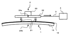
- FIG. 3 shows a schematic diagram for explaining a measurement method when a flat glass plate is used as a substrate.
- FIG. 3 shows a case where the dynamic friction coefficient of the surface of the flat glass plate (11) is measured.
- the measurement method will be specifically described in the case of the coated article (1) in which the film (12) is formed on the glass plate (11).
- a wiper rubber specimen (2) to which the wiper rubber (21) is attached is manufactured as follows.
- Two wiper rubbers for example, “Part No. 85214-22420”, which is cut into a length of 10 cm in the vicinity of the center of the lower surface side of the 15 ⁇ 15 cm plate-like body (22), 10 cm in length, Affix the replacement parts with double-sided tape so that they are parallel.
- the reason why the two wiper rubbers are used in parallel is to stabilize the wiper rubber specimen (2).
- a weight (23) is placed on the central portion on the upper surface side of the plate-like body (22) such as a glass plate so that the total load including the plate-like body and the wiper rubber is 400 g (20 gf / cm). .
- the tip of the wiper rubber has a triangular shape and is flexible, it is difficult to accurately measure the contact area between the wiper rubber (21) and the coating (12). In such a case, it is effective to express the force applied to the wiper rubber by the weight applied per unit length by using the length instead of the area of the wiper rubber contacting the low friction coating.
- the wiper rubber specimen (2) produced as described above is placed on the coating (12) on the surface of the coated article (1) having a size of 30 ⁇ 30 cm, and pulled. Connect to the measuring device (4) by means of the tool (3).
- the wiper rubber (21) is pulled horizontally in a direction perpendicular to the length direction of the wiper rubber (21) at a speed of 50 cm / min.
- the tensile force is measured with an autograph (“DSS-10T”, manufactured by Shimadzu Corporation) as the measuring device (4). From the measured value when the tensile force is stabilized, the dynamic friction coefficient (total load / tensile force) in a dry state is obtained.
- a curved glass plate (curved glass plate) is used as a window glass of an automobile.
- the shape and hardness of the wiper rubber are devised so that the wiper rubber can contact the surface of the curved glass plate without any gap.
- FIG. 4 shows a schematic diagram in the case of measuring the dynamic friction coefficient of the coated article (1) in which the coating (12) is formed on such a curved glass plate (13).
- the mark (1) is marked on the place where the vertex of the coated article (1) is known (for example, the side surface of the cradle) and the wiper rubber specimen (2) (for example, the side surface of the plate-like body (22)) corresponding to this vertex.
- a center mark (24) is added. As shown in FIG.
- the low-friction coating-coated article of the present invention as described above can be used for, for example, an automobile or a windshield of a train that uses a wiper as a wiping member.
- the low-friction coating of the low-friction coating-coated article is provided on the side in contact with the wiper.
- the (B) chlorosilyl group-containing compound is a compound having at least one chlorosilyl group in the molecule, and the chlorosilyl group is a group represented by —SiCl n X 3-n , and n is 1 2, or 3, X is hydrogen or an alkyl group, alkoxyl group, or acyloxy group each having 1 to 10 carbon atoms.
- a compound having at least two chlorines is preferable, and at least two hydrogens in silane Si n H 2n + 2 (where n is an integer of 1 to 5) are substituted with chlorine to obtain other hydrogens.
- tetrachlorosilane (SiCl 4 ) trichlorosilane (SiHCl 3 ), trichloromonomethylsilane (Si (CH 3 ) Cl 3 ), dichlorosilane (SiH 2 Cl 2 ), and Cl— (SiCl 2 O) n -SiCl 3 (n is an integer of 1 to 10).
- n is an integer of 1 to 10
- the most preferred chlorosilyl group-containing compound is tetrachlorosilane.
- the solvent containing alcohol and / or water is used to cause the dehydrochlorination reaction by substituting the chloro group of the (B) chlorosilyl group-containing compound with an alkoxyl group or a hydroxyl group.
- an alcohol-based hydrophilic solvent and a ketone-based hydrophilic solvent are preferably used.
- alcohols are preferred, and chain saturated monohydric alcohols having 3 or less carbon atoms such as methanol, ethanol, 1-propanol and 2-propanol are particularly preferred because of their high evaporation rate at room temperature.
- Examples of ketone-based hydrophilic solvents include acetone and methyl ethyl ketone.
- the solvent does not necessarily include alcohol as long as the solvent includes water necessary to cause the dehydrochlorination reaction. Furthermore, the solvent does not need to be composed of only a hydrophilic solvent, and may contain a non-aqueous solvent such as hydrocarbon or fluorine.
- Colloidal silica is a sol in which ultrafine particles of silica with a particle size of 1 to 100 ⁇ m are dispersed in water or an alcohol-based dispersion medium, or a dry powder from which a dispersed group has been removed, but commercially available products can be used. It is.
- the sol include water-dispersed silica gels such as Nissan Chemical's Snowtex OL, Snowtex O, and Snowtex OUP, as well as organic solvent-dispersed silica gels such as MIBK-ST and XBA-ST manufactured by Nissan Chemical Co., Ltd. Examples thereof include Catalid SI-80P (silica gel) manufactured by Catalyst Kasei.
- this coating solution was applied to the substrate under conditions of a temperature of 10 to 40 ° C. and an absolute humidity of 1 ⁇ 10 ⁇ 3 to 18 ⁇ 10 ⁇ 3 kg / kg (DA), and the temperature was 10 to 40 ° C. and the absolute humidity.
- a low friction coating film is formed on the surface of the substrate by drying under conditions of 1 ⁇ 10 ⁇ 3 to 18 ⁇ 10 ⁇ 3 kg / kg (DA), and the low friction coating coated article of the present invention is manufactured. To do.
- the amount of (C) colloidal silica can be adjusted in order to adjust the surface roughness of the low friction coating.
- it is highly hydrophilic (for example, the contact angle is 10 ° or less) by applying a surface treatment to remove organic components on the surface. Articles can be manufactured.
- a coating having a two-layer structure is coated on the surface of the substrate by two coatings (hereinafter referred to as a two-coat type).
- a coating liquid that is directly applied to the substrate is used as a base layer coating liquid, and a film coated thereby is used as a base layer.
- the coating liquid applied on the base layer is used as the upper layer coating liquid, and the film coated thereby is used as the upper layer.
- the underlayer and the upper layer may have different surface states and properties. For example, when the underlayer is hydrophilic, a film having water repellency or an intermediate wettability between hydrophilicity and water repellency can be formed on the hydrophilic film.
- a chlorosilyl group-containing compound is dissolved in a solvent containing alcohol and / or water, and (B) the chloro group of the chlorosilyl group-containing compound is replaced with an alkoxyl group or a hydroxyl group to prepare an undercoat coating solution To do.
- This undercoat layer coating liquid is a coating liquid when (C) colloidal silica is not added to the coating liquid of the first production method.
- (D) Dissolve the (B) chlorosilyl group-containing compound in a silicone-based solvent to prepare an upper layer coating solution.
- examples of the (D) silicone solvent include decamethylcyclopentasiloxane, hexamethyldisiloxane, and octamethyltrisiloxane.
- these solvents those having high volatility are preferable, and specifically, those having a vapor pressure at 25 ° C. of 500 Pa or more, and more preferably 1000 Pa or more are preferable.
- the base layer coating solution was applied to the substrate under conditions of a temperature of 10 to 40 ° C. and an absolute humidity of 1 ⁇ 10 ⁇ 3 to 18 ⁇ 10 ⁇ 3 kg / kg (DA), and the temperature was 10 to 40 ° C.
- DA absolute humidity
- an upper layer coating solution is applied on the base layer of the base material under conditions of a temperature of 10 to 40 ° C. and an absolute humidity of 1 ⁇ 10 ⁇ 3 to 18 ⁇ 10 ⁇ 3 kg / kg (DA). Wash off the excess upper layer coating solution on the substrate surface using the solvent used for the preparation of the coating solution, and maintain a temperature of 10 to 40 ° C. and an absolute humidity of 1 ⁇ 10 ⁇ 3 to 18 ⁇ 10 ⁇ 3 kg / kg (DA). Under the condition, the substrate surface is left wet with this solvent for 1 second or longer. Thereafter, the silicone-based solvent on the substrate surface is washed away with an alcohol such as ethanol, and dried under conditions of a temperature of 10 to 40 ° C. and an absolute humidity of 1 ⁇ 10 ⁇ 3 to 18 ⁇ 10 ⁇ 3 kg / kg (DA). A low-friction coating film is formed on the surface of the substrate to produce the low-friction coating-coated article of the present invention.
- (C) colloidal silica can be added as necessary to adjust the surface roughness of the low friction coating.
- it is highly hydrophilic for example, the contact angle is 10 ° or less
- a coating liquid is prepared by dissolving (B) a chlorosilyl group-containing compound in (E) a hydrocarbon solvent. Then, this coating solution was applied to the substrate under conditions of a temperature of 10 to 40 ° C. and an absolute humidity of 1 ⁇ 10 ⁇ 3 to 18 ⁇ 10 ⁇ 3 kg / kg (DA), and immediately used for preparation of the coating solution ( E) Rinse excess coating solution on the substrate surface with a hydrocarbon solvent, 1 second under conditions of temperature 10 to 40 ° C.
- the hydrocarbon solvent includes normal paraffins such as n-butane, n-heptane, n-octane and n-nonane; isoparaffins such as isobutane and isopentane.
- normal paraffins such as n-butane, n-heptane, n-octane and n-nonane
- isoparaffins such as isobutane and isopentane.
- those having high volatility are preferable, and specifically, those having a vapor pressure at 25 ° C. of 500 Pa or more, and more preferably 1000 Pa or more are preferable.
- (C) colloidal silica can be added as necessary to adjust the surface roughness of the low friction coating.
- surface treatment is performed to remove organic components on the surface, resulting in a low-friction coating with a surface contact angle of 10 ° or less, and excellent hydrophilicity.
- a low-friction coated article can be produced.
- the preferred temperature range for coating, standing and drying is 15 to 35 ° C.
- the preferred absolute humidity range is 2 ⁇ 10 ⁇ 3 to 12 ⁇ 10 ⁇ 3. kg / kg (DA).
- any one of the above coating solutions is applied to the substrate under conditions of a temperature of 10 to 40 ° C. and an absolute humidity of 4.5 ⁇ 10 ⁇ 3 to 18 ⁇ 10 ⁇ 3 kg / kg (DA), and the temperature is 10 to 40 Dry under the conditions of ° C. and absolute humidity of 4.5 ⁇ 10 ⁇ 3 to 18 ⁇ 10 ⁇ 3 kg / kg (DA) to form a water repellent coating on the surface of the substrate.
- the formed water-repellent coating is divided into a base layer on the substrate surface and a water-repellent component on the base layer.
- the formed water-repellent coating is subjected to a surface treatment for removing the water-repellent component on the surface to form a low-friction coating, and the low-friction coating-coated article of the present invention can be produced.
- the fourth production method is characterized in that when a low-friction film is formed on a substrate, a water-repellent film is once formed under specific conditions and a surface treatment is performed to remove the water-repellent component on the surface. .
- a surface treatment is performed to remove the water-repellent component on the surface.
- the material of the coating when the water-repellent coating has a fluoroalkyl group will be described in detail.
- Various materials can be used as the material for forming the water-repellent coating, but in the present invention, the following materials can be preferably used.
- Examples of the silicon alkoxide that is the component (F) include tetramethoxysilane, tetraethoxysilane, tetrapropoxysilane, and tetrabutoxysilane.
- those having a relatively small molecular weight for example, tetraalkoxysilane composed of an alkoxyl group having 3 or less carbon atoms are preferably used because they easily form a dense film.
- These tetraalkoxysilane polymers may have an average degree of polymerization of 5 or less.
- the content of the component (F) in the coating liquid is preferably 0.01 to 2% by mass, more preferably 0.01 to 0.6% by mass in terms of silica, as will be described in detail later.
- a silane compound containing a fluoroalkyl group and containing a hydrolyzable group such as an alkoxyl group, an acyloxy group, or a chlorine group is preferably used.
- examples thereof include compounds represented by the following chemical formula (I).
- n is an integer of 0 to 12, preferably an integer of 3 to 12
- R is a divalent organic group having 2 to 10 carbon atoms (for example, a methylene group, an ethylene group, etc.), or a silicon atom and an oxygen atom.
- a group containing, X is a hydrogen atom or a monovalent hydrocarbon group having 1 to 4 carbon atoms (for example, an alkyl group, a cycloalkyl group, an allyl group) or a derivative thereof; p is 0, 1 or 2, Y is an alkoxyl group having 1 to 4 carbon atoms, an acyloxy group, or a halogen atom.
- C 8 F 17 CH 2 CH 2 Si (OCH 3) 3 Heputadekafuru B decyltrimethoxysilane
- C 8 F 17 CH 2 CH 2 Si (CH 3) (OCH 3) 2 heptadecafluorodecyl methyldimethoxysilane
- C 8 F 17 CH 2 CH 2 SiCl 3 heptadecafluorodecyl Trichlorosilane
- C 8 F 17 CH 2 CH 2 Si (CH 3 ) Cl 2 heptadecafluorodecylmethyldichlorosilane
- heptadecafluorodecyltrimethoxysilane and heptadecafluorodecyltrichlorosilane are particularly preferably used.
- the content of the component (B) in the coating liquid is preferably 0.00001 to 0.15 mass%, more preferably 0.0001 to 0.03 mass% in terms of silica, as will be described in detail later.
- the acid as component (H) volatile acids such as hydrochloric acid, hydrofluoric acid, nitric acid, and acetic acid are preferable from the viewpoint that they are volatilized by drying at room temperature and do not remain in the film. Among them, hydrochloric acid is highly volatile.
- the water-repellent film thus obtained has a relatively good appearance, exhibits high durability, and is relatively safe when handled.
- the concentration (acid concentration) of the component (H) in the coating liquid is preferably 0.001 to 3 N, more preferably 0.01 to 1 N, as will be described in detail later.
- dissolves an acid it is contained as needed and refined water is usually used.
- the content of the component (I) in the coating liquid is preferably in the range of 0 to 20% by mass, more preferably 0 to 10% by mass, and particularly preferably 0 to 5% by mass, as will be described in detail later.
- the above component (F) and component (G) are convenient for handling when dissolved in a solvent when preparing a coating composition.
- various solvents can be used, for example, hydrocarbons such as hexane, toluene, and cyclohexane; halogenated hydrocarbons such as methyl chloride, carbon tetrachloride, and trichloroethylene; acetone, methyl ethyl ketone, and the like.
- Organic solvents such as ketones; nitrogen-containing compounds such as diethylamine; alcohols; esters such as ethyl acetate can be used.
- alcohol solvents that easily dissolve acids are preferably used, and examples thereof include methanol, ethanol, 1-propanol, 2-propanol, butyl alcohol, amyl alcohol, and the like.
- a chain saturated monohydric alcohol having 3 or less carbon atoms such as methanol, ethanol, 1-propanol, and 2-propanol is more preferably used because of its high evaporation rate at room temperature.
- the coating liquid in the present invention includes, for example, a small amount of methyltrialkoxysilane (methyltrimethoxysilane, methyltriethoxysilane). , Methyltripropoxysilane, methyltributoxysilane, etc.) can be contained in an amount of 50% by mass or less of the silicon alkoxide content in terms of silica.
- the inside of the coating solution containing silicon alkoxide, fluoroalkyl group-containing silane compound, acid, solvent and water including those for dissolving the acid, impurities in the solvent, and those entering from the humidity of the atmosphere.
- hydrolysis reaction represented by the following formula (II) occurs between the silicon alkoxide and water using the acid as a catalyst.
- R is an alkyl group.
- silanol groups (—Si—OH) generated by the hydrolysis reaction undergo a dehydration condensation reaction as shown in the following formula (III) to form a siloxane bond (—Si—O—Si—).
- (-Si-OH) + (-Si-OH) ⁇ (-Si-O-Si-) + (H 2 O) (III) Whether or not the alkoxyl group of the silicon alkoxide undergoes a hydrolysis reaction in the coating liquid containing silicon alkoxide, fluoroalkyl group-containing silane compound, acid, solvent and water, as well as the same.
- silanol groups (—Si—OH) decomposed to each other undergo a dehydration condensation reaction as shown in the above formula (III) in the coating solution depends on the acid concentration of the solution, the silicon alkoxide or its hydrolyzate. It depends greatly on the concentration and water content. Specifically, when the acid concentration of the solution is in the range of 0.001 N to 3 N, the above reaction hardly occurs and the lower the concentration and moisture content of silicon alkoxide or its hydrolyzate, the less likely the above reaction occurs.
- the silicon alkoxide in the coating liquid suppresses the dehydration condensation reaction and keeps the monomer as much as possible, and when the coating liquid is applied to the substrate surface and dried, the above formula (II), formula Since the reaction (III) is caused to form a siloxane bond, a dense film can be formed at room temperature.
- silicon alkoxide is hydrolyzed and polycondensed in a solution as in the prior art, polymer bonds occur when the solution is applied to the surface of the substrate and dried, which makes it easy to create gaps. It was necessary to perform baking and curing in order to obtain a dense film instead of a film.
- the silicon alkoxide or its hydrolyzate in a coating liquid is a monomer or a polymer less than a 20-mer.
- the total of the monomer, the hydrolyzate, and the polymer less than 20 mer accounts for 80% by mass or more based on the entire silicon alkoxide, the polymer including 20 mer or more may be contained. There is no problem.
- the concentration of the acid catalyst in the coating solution is maintained at 0.001 to 3 N, preferably 0.01 to 1 N.
- the hydrolysis reaction of the remaining alkoxyl group of the above formula (II) and the dehydration condensation reaction of the above formula (III) are less likely to occur in the coating liquid before coating, and abruptly immediately after the coating liquid is applied. These reactions proceed.
- the concentration of the silicon alkoxide or the hydrolyzate thereof in the coating solution is as low as possible, coupled with the acid concentration of the coating solution, and the hydrolysis reaction of the remaining alkoxyl groups of the above formula (II), and The dehydration condensation reaction of formula (III) is preferable because it hardly occurs in the coating solution before coating.
- this concentration is too low, the thickness of the water-repellent film becomes too small, for example, the film thickness becomes less than 5 nm, and the ability to prevent the diffusion of the alkali component when the substrate contains an alkali component is reduced.
- the durability performance tends to be inferior.
- a preferable range of the concentration of the silicon alkoxide or its hydrolyzate in the coating solution is 0.01 to 2% by mass in terms of silica, and a more preferable range is 0.01 to 0.6% by mass.
- the thickness of the water repellent coating is preferably 5 to 200 nm, more preferably 5 to 100 nm, and still more preferably 5 to 50 nm.
- the concentration of the fluoroalkyl group-containing silane compound in the coating solution is too low, the water repellency is reduced. If the concentration is too high, the hardness of the film decreases. Therefore, the preferred concentration range of the fluoroalkyl group-containing silane compound in the coating solution is silica. It is 0.00001 to 0.15% by mass, more preferably 0.0001 to 0.03% by mass in terms of.
- the ratio of the content (mass converted to silica) of the fluoroalkyl group-containing silane compound to the silicon alkoxide content (mass converted to silica) in the coating solution is the silica in the coated and dried water-repellent film. Almost corresponds to the content of the fluoroalkyl group.
- the value of [fluoroalkyl group-containing silane compound amount (silica conversion)] / [silicon alkoxide or its hydrolyzate amount (silica conversion)] in terms of mass in the coating solution is 0.0005 to 0.5. It is preferably 0.0005 to 0.3, more preferably 0.0005 to 0.05.
- the concentration of water in the coating solution is preferably as small as possible. Accordingly, the concentration of water in the coating liquid is preferably 0 to 20% by mass, more preferably 0 to 10% by mass, and most preferably 0 to 5% by mass.
- the above formula in combination with the maintenance of the acid concentration of the coating solution and the concentration of the silicon alkoxide (or its hydrolyzate) in the coating solution
- the hydrolysis reaction of the remaining alkoxyl group of II) and the dehydration condensation reaction of the above formula (III) are less likely to occur in the coating solution before coating. Even if the concentration of water in the coating liquid is zero, the hydrolysis reaction is not hindered because moisture in the air is absorbed by the coating film after being applied to the substrate.
- the concentration of water in the coating solution is usually It becomes 0.1 mass% or more.
- the coating liquid according to the present invention contains acid and water so that the mass ratio of acid / water is preferably 0.002 or more, more preferably 0.02 or more. This is because the hydrolysis reaction of the remaining alkoxyl group of the above formula (II) and the dehydration condensation reaction of the formula (III) are less likely to occur in the coating solution before coating.
- a solution in which a silicon alkoxide, a fluoroalkyl group-containing silane compound, and an acid are dissolved in the above-described solvent is stirred, in the solution, the silicon alkoxide mainly forms a hydrolyzate by the reaction of the above formula (II), and A part of the hydrolyzate undergoes a dehydration condensation reaction by the reaction of the formula (III).
- a coating solution is prepared, and in this coating solution, silicon alkoxide is present in the form of a monomer (including a hydrolyzate) or a polymer of less than 20 mer.
- silicon alkoxide is present in the form of a monomer (including a hydrolyzate) or a polymer of less than 20 mer.
- the coating film is generated in the coating film, and as a result, the bond between the base material and the underlying layer constituting the water-repellent coating is strengthened, and the main component is silica having a film thickness of 5 to 200 nm. A highly dense film is formed.
- the reactivity at the time of film formation is high, and the reaction is performed at room temperature to form a very dense film, and subsequent baking is not necessary.
- the resulting water-repellent film contains siloxane.
- the prior art requires firing at a higher temperature.
- a chlorosilyl group-containing compound and (G) a fluoroalkyl group-containing silane compound are dissolved in a solvent containing (A) alcohol and / or moisture, and (B) It is also possible to use a solution in which the chloro group of the chlorosilyl group-containing compound is substituted with an alkoxyl group or a hydroxyl group and the silicon alkoxide or a hydrolyzate thereof is a monomer or a polymer of 19-mer or less.
- a chlorosilyl group reacts in solution, during its preparation, during storage and during film formation, and changes to a siloxane bond (—Si—O—Si—). Part of the changed siloxane bond forms a siloxane bond with the fluoroalkyl group-containing silane compound, and the other part forms a siloxane bond with the substrate surface.
- the chlorosilyl group-containing compound in the solution forms an alkoxide by a dehydrochlorination reaction with the alcohol solvent as shown in the following formula (IV).
- the chlorosilyl group-containing compound undergoes a hydrolysis reaction with moisture contained in a trace amount in an alcohol solvent or atmosphere, and hydrogen chloride is removed as shown in Formula (V) (dehydrochlorination reaction).
- silanol ..Si-OH
- R is an alkyl group. (..Si-Cl) + (ROH) ⁇ (..
- the reactivity of the chloro group of the chlorosilyl group-containing compound is extremely high. For this reason, the chlorosilyl group-containing compound in the alcohol solvent reacts with most of the chloro groups, and (..Si-OR), (..Si-OH), (..Si-O-Si ..), It has changed to (HCl). That is, in the above-mentioned solution, hydrochloric acid is also contained in the alcohol solvent in addition to the silicon alkoxide or a hydrolyzate thereof and the fluoroalkyl group-containing silane compound.
- the coating and drying conditions are specified. Specifically, the coating and drying temperatures are 10 to 40 ° C., respectively, and the absolute humidity is 4.5 ⁇ 10 ⁇ 3 to 18 ⁇ 10 ⁇ 3 kg / kg (DA), respectively. Preferably, the coating and drying temperatures are each 15 to 35 ° C., and the absolute humidity is 5 ⁇ 10 ⁇ 3 to 12 ⁇ 10 ⁇ 3 kg / kg (DA), respectively.
- absolute humidity means the humidity which represented the quantity of the water vapor
- a surface treatment for selectively removing the water-repellent component constituting the water-repellent coating and the fluoroalkyl group of the underlayer is performed.
- the surface treatment method include plasma jet treatment, UV treatment, ozone treatment, and baking treatment. In consideration of workability, plasma jet treatment is preferable. If the contact angle is 10 ° or less, some fluoroalkyl groups may remain.
- the plasma jet treatment can decompose the bond between the alkyl group and Si in the perfluoroalkylsilane that exhibits the water repellency function, and the water repellency function can be lost.
- the plasma jet treatment can be realized by relatively moving the plasma jet irradiation gun along the surface of the water repellent coating. Since the movement of the plasma jet irradiation gun can be realized without difficulty, the intended treatment can be easily performed even if the water repellent coating has a curved surface.
- Plasma jet processing is performed by using a plasma jet irradiation gun.
- the plasma jet irradiation gun is set to operate with an output power of about 0.5 kw, for example, and is placed 5 to 15 mm away from the object to be processed. It is preferable to do.
- a plasma jet flow having a stable output can be generated.
- the “converted speed” is a speed obtained by dividing the speed of the plasma jet irradiation gun that moves parallel to the surface of the object to be processed by the number of times of processing with the plasma jet of the object to be processed.
- the lower limit value of the conversion speed is more preferably 10 mm / sec or more, and further preferably 20 mm / sec or more.
- the upper limit value is more preferably 50 mm / sec or less, and further preferably 40 mm / sec or less.
- (C) colloidal silica can be added as necessary to adjust the surface roughness of the low friction coating.
- the fourth production method of the present invention can be used as a method for producing a low-friction film-coated article having water repellency, except for a surface treatment for removing a water-repellent component.
- the surface treatment does not have to be performed immediately after the production of the low-friction coating-coated article having water repellency, and can be performed on what has been used or stored as the low-friction coating-coated article having water repellency.
- water repellency or hydrophilicity is selected according to the user's preference.
- a window glass having such different characteristics is firstly prepared by using a common coating liquid and a low friction coating film-coated glass plate having water repellency by a common facility (hereinafter referred to as “glass pane”). Manufactured simply as a water-repellent glass plate). Thereafter, a surface treatment is performed on the water-repellent glass plate to obtain a hydrophilic low-friction coating-coated glass plate (hereinafter simply referred to as a hydrophilic glass plate). Many vehicle users tend to select a water-repellent glass plate that does not require the wiper to operate during high-speed running. Therefore, manufacturing the window glass as a water-repellent glass plate and manufacturing the hydrophilic glass plate by surface treatment as necessary is effective in terms of manufacturing cost and inventory management.
- Example 1 and Example 6 As a base material, a glass plate whose surface to be coated was washed with celico was prepared. 98.9 g of ethanol (manufactured by Kanto Chemical) as an alcohol solvent, 0.4 g of tetrachlorosilane (manufactured by Shin-Etsu Silicone) as a chlorosilyl group-containing compound and colloidal silica having a particle diameter of 40 to 50 mm (Snowtex OL: manufactured by Nissan Chemical Co., Ltd.) 0 0.7 g was added and stirred for 30 minutes to prepare a coating solution.
- ethanol manufactured by Kanto Chemical
- tetrachlorosilane manufactured by Shin-Etsu Silicone
- colloidal silica having a particle diameter of 40 to 50 mm Snowtex OL: manufactured by Nissan Chemical Co., Ltd.
- This coating solution was applied to the surface of a glass plate that had been cleaned with celico using a flow coating method at a temperature of 20 ° C. and a relative humidity of 30% RH (absolute humidity 4.3 ⁇ 10 ⁇ 3 kg / kg (DA)).
- the glass plate was coated with the low friction coating film of Example 6 by drying for about 30 minutes under the same conditions.
- the contact angle and the dynamic friction coefficient were measured for the coating of the low friction coating coated glass plate of Example 6, and the results are shown in Table 1 below.
- the low-friction coating-coated glass plate of Example 1 was obtained by subjecting the coating of the low-friction coating-coated glass plate of Example 6 to plasma jet treatment, which will be described later, which is a surface treatment for removing organic components on the surface. .
- the surface roughness, contact angle, and dynamic friction coefficient of the coating on the side of the low-friction coating-coated glass of Example 1 were measured, and the results are shown in Table 1.
- a plasma treatment apparatus (PJ-1: manufactured by Corotech) was used under the following conditions.
- PJ-1 manufactured by Corotech
- ⁇ Output 0.5kW
- ⁇ Distance between head and workpiece 8mm
- Conversion head feed speed 20mm / sec
- Flow velocity of plasma jet about 7m / sec
- Example 2 and Example 7 As a base material, a glass plate whose surface to be coated was washed with celico was prepared. Tetrachlorosilane 0.5g was added to ethanol 99.5g, and it stirred for 30 minutes, and produced the base layer coating liquid. 0.5 g of tetrachlorosilane was added to 99.5 g of decamethylcyclopentasiloxane (KF-995: manufactured by Shin-Etsu Silicone), which is a silicone solvent, and stirred for 30 minutes to prepare an upper layer coating solution. Apply the flow coating method to the surface of a glass plate that has been washed with a ground layer coating solution under the conditions of a temperature of 20 ° C.
- KF-995 decamethylcyclopentasiloxane
- the upper layer coating solution is applied on the underlayer of the underlayer-coated glass plate by a flow coat method under the conditions of a temperature of 20 ° C. and a relative humidity of 30% RH (absolute humidity 4,3 ⁇ 10 ⁇ 3 kg / kg (DA)). Immediately after application, the excess upper layer coating solution on the surface of the glass plate was washed away using the solvent used in the production of the upper layer coating solution, and the glass plate surface was left wet with this solvent for 1 minute under the same conditions. .
- Example 7 The low-friction coating-coated glass plate of Example 2 was obtained by subjecting the coating of the low-friction coating-coated glass plate of Example 7 to plasma jet treatment described below under the same conditions as in Example 1. The surface roughness, contact angle, and dynamic friction coefficient were measured for the coating of the low friction coating coated glass plate of Example 2 and the results are shown in Table 1.
- Example 3 and Example 8 As a base material, a glass plate whose surface to be coated was washed with celico was prepared. 0.5 g of tetrachlorosilane (made by Shin-Etsu Silicone), which is a chlorosilyl group-containing compound, was added to 99.5 g of an isoparaffin-based hydrocarbon solvent (Isosol 300: manufactured by Shin Nippon Petrochemical Co., Ltd.) and stirred for 30 minutes to prepare a coating solution. . This coating solution was applied to the surface of a glass plate that had been cleaned with celico under the conditions of a temperature of 20 ° C.
- the low-friction coating-coated glass plate of Example 3 was obtained by subjecting the coating of the low-friction coating-coated glass plate of Example 8 to plasma jet treatment described below under the same conditions as in Example 1.
- the surface roughness, the contact angle, and the dynamic friction coefficient were measured for the coating of the low-friction coating-coated glass plate of Example 3, and the results are shown in Table 1.
- Example 4 and Reference Example 1 97.38 g of ethanol (water content 0.35 mass%), 0.6 g of tetraethoxysilane (manufactured by Shin-Etsu Silicone) as silicon alkoxide and heptadecafluorodecyltrimethoxysilane (CF as organosilane containing a fluoroalkyl group) 3 (CF 2 ) 7 (CH 2 ) 2 Si (OCH 3 ) 3 , manufactured by Shin-Etsu Silicone Co., Ltd.
- tetraethoxysilane manufactured by Shin-Etsu Silicone
- CF heptadecafluorodecyltrimethoxysilane
- this water-repellent coating solution is applied to the surface of a cleaned glass substrate by a flow coating method under conditions of room temperature (20 ° C.) and relative humidity of 40% RH (5.9 ⁇ 10 ⁇ 3 kg / kg (DA)). And applied.
- the glass plate was coated with the low friction coating film of Reference Example 1 by drying for about 30 minutes under the same conditions.
- This low-friction coating-coated glass plate corresponds to the water-repellent coating-coated glass plate of Example 2 of Patent Document 4.
- the surface roughness, the contact angle, and the dynamic friction coefficient were measured for the coating of the low friction coating coated glass plate of Reference Example 1, and the results are shown in Table 1.
- the low-friction coating-coated glass plate of Reference Example 1 was subjected to plasma jet treatment under the same conditions as in Example 1 to obtain the low-friction coating-coated glass plate of Example 4.
- the surface roughness, the contact angle, and the dynamic friction coefficient were measured for the coating of the low friction coating coated glass plate of Example 4, and the results are shown in Table 1.
- Example 5 and Reference Example 2 The same conditions as in Reference Example 1 except that the relative humidity was changed to 55% RH (absolute humidity: 8.1 ⁇ 10 ⁇ 3 kg / kg (DA)) as a condition for applying and drying the water repellent coating solution.
- RH absolute humidity: 8.1 ⁇ 10 ⁇ 3 kg / kg (DA)
- DA absolute humidity: 8.1 ⁇ 10 ⁇ 3 kg / kg (DA)
- a low friction coating-coated glass plate of Reference Example 2 was obtained.
- This low-friction coating-coated glass plate corresponds to the water-repellent coating-coated glass plate of Example 3 of Patent Document 4.
- the surface roughness, the contact angle, and the dynamic friction coefficient were measured for the coating of the low friction coating coated glass plate of Reference Example 2, and the results are shown in Table 1.
- the low-friction coating-coated glass plate of Example 5 was obtained by subjecting the coating of the low-friction coating-coated glass plate of Reference Example 2 to plasma jet treatment under the same conditions as in Example 1.
- the contact angle and the dynamic friction coefficient were measured for the coating of the low friction coating coated glass plate of Example 5, and the results are shown in Table 1.
- a glass plate was prepared and used as an uncoated glass plate of Comparative Example 4 (hereinafter referred to as a normal glass plate).
- the contact angle and dynamic friction coefficient were measured on the surface of the normal glass plate of Comparative Example 4, and the results are shown in Table 1.
- Plasma jet treatment was performed on the surface of the normal glass plate of Comparative Example 4 under the same conditions as in Example 1 to obtain a normal glass plate after the plasma jet treatment of Comparative Example 2.
- Surface roughness, contact angle, and dynamic friction coefficient were measured on the treated surface of the normal glass plate of Comparative Example 2, and the results are shown in Table 1.
- the dynamic friction coefficient in the wet state of the coated glass plate having hydrophilicity or intermediate wettability between hydrophilicity and water repellency is 0.30 or less, judder improvement can be expected.
- the dynamic friction coefficients in the wet state of the coated glass plates in Examples 6 to 8 before the plasma jet treatment were 0.26, 0.19, and 0.19, respectively, which were smaller than 0.28 in Comparative Example 4. I understand that.
- the dynamic friction coefficients in the wet state of the coated glass plates in Examples 1 to 5 after the plasma jet treatment were 0.27, 0.26, 0.25, 0.15, and 0.15, respectively. It can be seen that the coefficient of dynamic friction in the wet state is smaller than 0.31.
- the dynamic friction coefficient in the wet state in Examples 4 and 5 is 0.20 or less, which is about half the value of the dynamic friction coefficient 0.31 in the wet state in Comparative Example 2, and is low in the wet state. It can be seen that the friction is improved.
- the difference in the dynamic friction coefficient of the film-coated glass plate in Example 4 is 0.43, which is larger than that of the normal glass plate in Comparative Example 4, but this film-coated glass plate has high hydrophilicity, Since water easily spreads in the form of a film, a large difference in the dynamic friction coefficient during sufficient rain does not hinder good wiper operation.
- the difference in dynamic friction coefficient in Examples other than Example 4 is 0.30 or less, the difference in dynamic friction coefficient in Examples 1 to 3, 6 to 8 is 0.20 or less, and It can be seen that the difference in the dynamic friction coefficient between 2, 6, and 7 is 0.10 or less.
- the coating-coated glass plate of Comparative Example 3 has improved hydrophilicity than that of the normal glass plate of Comparative Example 4, but the wet dynamic friction coefficient is higher than that of the normal glass plate of Comparative Example 4.
- the difference in the dynamic friction coefficient is effective in improving judder, and the difference in the dynamic friction coefficient between Reference Examples 1 and 2 is 0.00 and 0.03, which are 0.10 or less, respectively. Therefore, the judder improvement effect was high.
- the surface of the film-coated glass plate of Reference Examples 1 and 2 has a high water repellency because the value of the contact angle exceeds 100 °.
- the surface of the normal glass plate of Comparative Example 4 had a contact angle value of 53.3 ° and was slightly higher in hydrophilicity, but this was completely removed by wiping in step 2 of the measurement method described above. This is thought to be due to the influence of residues such as organic matter that did not exist.
- the contact angle of each glass plate after the plasma jet treatment was as follows.
- the surfaces of the coating-coated glass plates of Examples 1 to 5 have contact angles of 0.7 °, 2.7 °, 2.9 °, 6.7 °, and 7.2 ° (10 ° or less), respectively.
- the contact angles of Examples 1 to 3 are 5 ° or less, which indicates that excellent hydrophilicity is exhibited.
- the surface of the film-coated glass plate of Comparative Example 1 also has excellent hydrophilicity with a contact angle of 4.7 °.
- the surface of the normal glass plate of Comparative Example 2 also has excellent hydrophilicity with a contact angle of 3.8 °. This is hydrophilic because the organic residue and water repellent components (Reference Examples 1 and 2) contained in the coating liquid remaining on the coating surface and in the coating were removed by the plasma jet treatment. It is considered that the properties of the film mainly composed of silicon oxide appear. And it turns out that the surface of a normal glass plate originally has the outstanding hydrophilicity.
- the graph of the wet state after the plasma jet treatment has a tendency of a straight line, unlike the graph before the plasma jet treatment, and the slope thereof is small. Therefore, the surface roughness Ra where no measurement value exists is wide even in the range exceeding 15.2 nm.
- the wet dynamic friction coefficient is expected to be 0.30 or less in the range.
- the surface roughness Ra after the plasma jet treatment is 0.2 nm (Comparative Example 1)
- the dynamic friction coefficient in the wet state is approximately the same as that of the normal glass plate (Comparative Example 2), but the surface roughness Ra is 0.9 nm.
- the dynamic friction coefficient in the wet state is usually about half that of the glass plate (Comparative Example 2). Therefore, if the surface roughness Ra is 0.5 or more, the dynamic friction coefficient in the wet state is 0.00. Expected to be 30 or less.
- the upper limit value of the surface roughness Ra after the plasma jet treatment is not particularly limited. From the graph of the approximate curve in the wet state shown in FIG. 1 (linear (Wet)), it is expected that the dynamic friction coefficient in the wet state will be 0.30 or less even if the surface roughness Ra is about 20 nm. From the graphs of the two approximate curves shown in FIG. 1 (secondary curve (Dry) and linear (Wet)), if the surface roughness Ra after the plasma jet treatment is about 2 nm to about 18 nm, the dynamic friction coefficient The difference is expected to be 0.30 or less.
- the lower limit of the surface roughness Ra after the surface treatment such as plasma jet treatment is preferably 0.5 nm, and the upper limit is not particularly limited, but 20 nm is preferable.
- the range of the surface roughness Ra after the surface treatment is more preferably 2 to 18 nm. From the measured value (Dry) of the wet state and the graph of the approximate curve (secondary curve (Wet)) shown in FIG. 2, if the surface roughness Ra before the plasma jet treatment is about 2 nm to 16 nm, the wet state It can be seen that the dynamic friction coefficient is about 0.30. From the graphs of the two approximate curves shown in FIG.
- the difference in the dynamic friction coefficient in this range is 0.20 or less, particularly 0.10 or less. . Therefore, the lower limit of the surface roughness Ra before the surface treatment is preferably 2 nm, and the upper limit is preferably 16 nm.
Landscapes
- Chemical & Material Sciences (AREA)
- Materials Engineering (AREA)
- Engineering & Computer Science (AREA)
- Chemical Kinetics & Catalysis (AREA)
- General Chemical & Material Sciences (AREA)
- Geochemistry & Mineralogy (AREA)
- Life Sciences & Earth Sciences (AREA)
- Organic Chemistry (AREA)
- Composite Materials (AREA)
- Inorganic Chemistry (AREA)
- Dispersion Chemistry (AREA)
- Application Of Or Painting With Fluid Materials (AREA)
- Surface Treatment Of Glass (AREA)
Abstract
基材と、該基材上に形成された低摩擦性被膜とを有し、前記低摩擦性被膜が払拭部材と接触する側に形成されてなり、前記低摩擦性被膜が酸化珪素を主成分とし、前記低摩擦性被膜の表面と前記払拭部材との間の動摩擦係数の測定条件として、前記低摩擦性被膜の表面を前記払拭部材が移動する速度を50cm/minとしたとき、湿潤状態の動摩擦係数が、0.30以下である低摩擦性被膜被覆物品、および当該低摩擦性被膜被覆物品を製造する方法である。
Description
本発明は、ガラスなどの基材表面に低摩擦性被膜を形成してなる低摩擦性被膜被覆物品およびその製造方法に関する。
従来、自動車用ガラスにおけるワイパー動作の改善は、主にワイパーの改善によるものであり(例えば、特許文献1(特開平6-262943号公報)および特許文献2(特開平8-268234号公報)参照)、窓ガラスを改善するようなことはほとんどなかった。
一方で、自動車用ガラスに撥水性を付与する技術が普及したことに伴い、撥水性ガラス板が通常のガラス板(親水性ガラス板)と比べてワイパー動作が低下し、ひどい場合にはワイパーのジャダー(ビビリともいう)が発生する問題から、ワイパー動作を向上させる撥水性ガラス板が提案されている(例えば、特許文献3(特開2004-306010号公報)および特許文献4(WO2007/018184)参照)。
撥水性ガラス板に関する改善は多くなされているが、ワイパー動作を改善するための親水性や、親水性と撥水性との中間の濡れ性を有するガラス板の改善例は殆どなかった。これは、通常親水性のガラス板に親水性を高める処理を行っても、撥水性処理ほどの効果が使用者に実感されにくいためと考えられる。
一方で、自動車用ガラスに撥水性を付与する技術が普及したことに伴い、撥水性ガラス板が通常のガラス板(親水性ガラス板)と比べてワイパー動作が低下し、ひどい場合にはワイパーのジャダー(ビビリともいう)が発生する問題から、ワイパー動作を向上させる撥水性ガラス板が提案されている(例えば、特許文献3(特開2004-306010号公報)および特許文献4(WO2007/018184)参照)。
撥水性ガラス板に関する改善は多くなされているが、ワイパー動作を改善するための親水性や、親水性と撥水性との中間の濡れ性を有するガラス板の改善例は殆どなかった。これは、通常親水性のガラス板に親水性を高める処理を行っても、撥水性処理ほどの効果が使用者に実感されにくいためと考えられる。
特許文献1,2のようなワイパーが提案される中、近年、ワイパーのデザイン性向上からフラットワイパーが使用され始めている。このフラットワイパーは中央部の点のみで窓ガラスに押し付ける構造が採用されることが多く、従来品に比べてワイパー動作が低下しやすい。従って、フラットワイパーの場合、親水性ガラス板であっても、従来のワイパーに比べるとワイパー動作性が低くなることがある。
このように、ワイパーの形態が変わってもジャダーの発生が抑制されたワイパー動作性の高いガラス板が望まれているが、現時点で有効なガラス板は見出されていない。
本発明は、上記課題を解決することを目的とする。すなわち、本発明は、ジャダーの発生が抑制される等、ワイパーの動作性に優れる低摩擦性被膜被覆物品を提供することを目的とする。また、本発明の低摩擦性被膜被覆物品を効率よく製造することができる低摩擦性被膜被覆物品の製造方法を提供することを目的とする。
本発明者は、前記目的を達成するために鋭意研究を重ねた結果、下記本発明に想到し、上記課題を解決し得ることを見出した。
すなわち、本発明は、
(1)基材と、該基材上に形成された低摩擦性被膜とを有し、前記低摩擦性被膜が払拭部材と接触する側に形成されてなり、前記低摩擦性被膜が酸化珪素を主成分とし、前記低摩擦性被膜の表面と前記払拭部材との間の動摩擦係数の測定条件として、前記低摩擦性被膜の表面を前記払拭部材が移動する速度を50cm/minとしたとき、湿潤状態の動摩擦係数が、0.30以下である低摩擦性被膜被覆物品、
(2)前記低摩擦性被膜の表面における水の接触角が、80°以下である(1)に記載の低摩擦性被膜被覆物品、
(3)乾燥状態と前記湿潤状態との間における動摩擦係数の差の絶対値が、0.30以下である(1)または(2)に記載の低摩擦性被膜被覆物品、
(4)前記水の接触角が、20°以下である(2)または(3)に記載の低摩擦性被膜被覆物品、
(5)前記低摩擦性被膜の表面から表面処理により有機物が除去されている(1)~(4)のいずれかに記載の低摩擦性被覆物品、
(6)前記水の接触角が、10°以下である(5)に記載の低摩擦性被膜被覆物品、
(7)前記表面処理が、プラズマジェット処理である(5)または(6)に記載の低摩擦性被膜被覆物品、
(8)(A)アルコールおよび/または水を含む溶媒に(B)クロロシリル基含有化合物と(C)コロイダルシリカとを溶解し、(B)クロロシリル基含有化合物のクロロ基を、アルコキシル基または水酸基に置換したコーティング液を作製し、温度10~40℃、絶対湿度1×10-3~18×10-3kg/kg(DA)の条件で、前記コーティング液を基材に塗布し、温度10~40℃、絶対湿度1×10-3~18×10-3kg/kg(DA)の条件で乾燥する低摩擦性被膜被覆物品の製造方法、
(9)(A)アルコールおよび/または水を含む溶媒に(B)クロロシリル基含有化合物を溶解し、(B)クロロシリル基含有化合物のクロロ基を、アルコキシル基または水酸基に置換した下地層コーティング液を作製し、(D)シリコーン系溶媒に(B)クロロシリル基含有化合物を溶解して上地層コーティング液を作製し、温度10~40℃、絶対湿度1×10-3~18×10-3kg/kg(DA)の条件で、前記下地層コーティング液を基材に塗布し、温度10~40℃、絶対湿度1×10-3~18×10-3kg/kg(DA)の条件で乾燥することにより、前記基材の表面に下地層を形成し、温度10~40℃、絶対湿度1×10-3~18×10-3kg/kg(DA)の条件で、前記基材の前記下地層上に前記上地層コーティング液を塗布し、前記上地層コーティング液の作製に用いた溶媒を用いて前記基材表面の余剰の前記上地層コーティング液を洗い流し、温度10~40℃、絶対湿度1×10-3~18×10-3kg/kg(DA)の条件で1秒以上静置し、その後、アルコールで前記基材表面のシリコーン系溶媒を洗い流し、温度10~40℃、絶対湿度1×10-3~18×10-3kg/kg(DA)の条件で乾燥する低摩擦性被膜被覆物品の製造方法、
(10)(E)炭化水素系溶媒に(B)クロロシリル基含有化合物を溶解してコーティング液を作製し、温度10~40℃、絶対湿度1×10⁻³~18×10-3kg/kg(DA)の条件で、前記コーティング液を基材に塗布し、コーティング液の作製に用いた前記(E)炭化水素系溶媒を用いて前記基材表面の余剰のコーティング液を洗い流し、温度10~40℃、絶対湿度1×10-3~18×10-3kg/kg(DA)の条件で1秒以上静置し、アルコールで前記基材表面の前記(E)炭化水素系溶媒を洗い流し、温度10~40℃、絶対湿度1×l0-3~18×10-3kg/kg(DA)の条件で乾燥する低摩擦性被膜被覆物品の製造方法、
(11)(F)シリコンアルコキシドおよび/またはその加水分解物0.01~2質量%(シリカ換算)、(G)フルオロアルキル基含有シラン化合物0.00001~0.15質量%(シリカ換算)、(H)酸、および(I)水0~20質量%を含有し、酸濃度が0.001~3規定であるコーティング液、または、(B)クロロシリル基含有化合物と(G)フルオロアルキル基含有シラン化合物とを、(A)アルコールおよび/または水分を含む溶媒に溶解し、前記(B)クロロシリル基含有化合物のクロロ基を、アルコキシル基または水酸基に置換したコーティング液を、温度10~40℃、絶対湿度4.5×10-3~18×10-3kg/kg(DA)の条件で基材に塗布し、温度10~40℃、絶対湿度4.5×10-3~18×10-3kg/kg(DA)の条件で乾燥した後、表面の撥水成分を除去する表面処理を施して親水性皮膜を形成する低摩擦性被膜被覆物品の製造方法、
(12)前記表面処理がプラズマジェット処理である(11)に記載の低摩擦性被膜被覆物品の製造方法、を提供するものである。
(1)基材と、該基材上に形成された低摩擦性被膜とを有し、前記低摩擦性被膜が払拭部材と接触する側に形成されてなり、前記低摩擦性被膜が酸化珪素を主成分とし、前記低摩擦性被膜の表面と前記払拭部材との間の動摩擦係数の測定条件として、前記低摩擦性被膜の表面を前記払拭部材が移動する速度を50cm/minとしたとき、湿潤状態の動摩擦係数が、0.30以下である低摩擦性被膜被覆物品、
(2)前記低摩擦性被膜の表面における水の接触角が、80°以下である(1)に記載の低摩擦性被膜被覆物品、
(3)乾燥状態と前記湿潤状態との間における動摩擦係数の差の絶対値が、0.30以下である(1)または(2)に記載の低摩擦性被膜被覆物品、
(4)前記水の接触角が、20°以下である(2)または(3)に記載の低摩擦性被膜被覆物品、
(5)前記低摩擦性被膜の表面から表面処理により有機物が除去されている(1)~(4)のいずれかに記載の低摩擦性被覆物品、
(6)前記水の接触角が、10°以下である(5)に記載の低摩擦性被膜被覆物品、
(7)前記表面処理が、プラズマジェット処理である(5)または(6)に記載の低摩擦性被膜被覆物品、
(8)(A)アルコールおよび/または水を含む溶媒に(B)クロロシリル基含有化合物と(C)コロイダルシリカとを溶解し、(B)クロロシリル基含有化合物のクロロ基を、アルコキシル基または水酸基に置換したコーティング液を作製し、温度10~40℃、絶対湿度1×10-3~18×10-3kg/kg(DA)の条件で、前記コーティング液を基材に塗布し、温度10~40℃、絶対湿度1×10-3~18×10-3kg/kg(DA)の条件で乾燥する低摩擦性被膜被覆物品の製造方法、
(9)(A)アルコールおよび/または水を含む溶媒に(B)クロロシリル基含有化合物を溶解し、(B)クロロシリル基含有化合物のクロロ基を、アルコキシル基または水酸基に置換した下地層コーティング液を作製し、(D)シリコーン系溶媒に(B)クロロシリル基含有化合物を溶解して上地層コーティング液を作製し、温度10~40℃、絶対湿度1×10-3~18×10-3kg/kg(DA)の条件で、前記下地層コーティング液を基材に塗布し、温度10~40℃、絶対湿度1×10-3~18×10-3kg/kg(DA)の条件で乾燥することにより、前記基材の表面に下地層を形成し、温度10~40℃、絶対湿度1×10-3~18×10-3kg/kg(DA)の条件で、前記基材の前記下地層上に前記上地層コーティング液を塗布し、前記上地層コーティング液の作製に用いた溶媒を用いて前記基材表面の余剰の前記上地層コーティング液を洗い流し、温度10~40℃、絶対湿度1×10-3~18×10-3kg/kg(DA)の条件で1秒以上静置し、その後、アルコールで前記基材表面のシリコーン系溶媒を洗い流し、温度10~40℃、絶対湿度1×10-3~18×10-3kg/kg(DA)の条件で乾燥する低摩擦性被膜被覆物品の製造方法、
(10)(E)炭化水素系溶媒に(B)クロロシリル基含有化合物を溶解してコーティング液を作製し、温度10~40℃、絶対湿度1×10⁻³~18×10-3kg/kg(DA)の条件で、前記コーティング液を基材に塗布し、コーティング液の作製に用いた前記(E)炭化水素系溶媒を用いて前記基材表面の余剰のコーティング液を洗い流し、温度10~40℃、絶対湿度1×10-3~18×10-3kg/kg(DA)の条件で1秒以上静置し、アルコールで前記基材表面の前記(E)炭化水素系溶媒を洗い流し、温度10~40℃、絶対湿度1×l0-3~18×10-3kg/kg(DA)の条件で乾燥する低摩擦性被膜被覆物品の製造方法、
(11)(F)シリコンアルコキシドおよび/またはその加水分解物0.01~2質量%(シリカ換算)、(G)フルオロアルキル基含有シラン化合物0.00001~0.15質量%(シリカ換算)、(H)酸、および(I)水0~20質量%を含有し、酸濃度が0.001~3規定であるコーティング液、または、(B)クロロシリル基含有化合物と(G)フルオロアルキル基含有シラン化合物とを、(A)アルコールおよび/または水分を含む溶媒に溶解し、前記(B)クロロシリル基含有化合物のクロロ基を、アルコキシル基または水酸基に置換したコーティング液を、温度10~40℃、絶対湿度4.5×10-3~18×10-3kg/kg(DA)の条件で基材に塗布し、温度10~40℃、絶対湿度4.5×10-3~18×10-3kg/kg(DA)の条件で乾燥した後、表面の撥水成分を除去する表面処理を施して親水性皮膜を形成する低摩擦性被膜被覆物品の製造方法、
(12)前記表面処理がプラズマジェット処理である(11)に記載の低摩擦性被膜被覆物品の製造方法、を提供するものである。
本発明によれば、ジャダーの発生が抑制される等、ワイパーの動作性に優れる低摩擦性被膜被覆物品を提供することができる。また、本発明の低摩擦性被膜被覆物品を効率よく製造することができる低摩擦性被膜被覆物品の製造方法を提供することができる。
[低摩擦性被膜被覆物品]
本発明の低摩擦性被膜被覆物品は、基材と、該基材上に形成された低摩擦性被膜とを有する。低摩擦性被膜は、払拭部材(例えば、ワイパー等)と接触する側に形成されてなり、酸化珪素を主成分としている。
払拭部材としては、車両のワイパーや自動車の開閉可能な窓(例えばドアの窓やルーフ)のウェザーストリップ、建物の窓の清掃に用いられるワイパーなどがある。払拭部材の低摩擦性被膜との接触部には、ラバー、スポンジ状の樹脂および布状のものを用いることができる。以下の説明においては、ワイパーに用いられるラバー(単に、ワイパーラバーという)を用いることとする。
本発明の低摩擦性被膜被覆物品は、基材と、該基材上に形成された低摩擦性被膜とを有する。低摩擦性被膜は、払拭部材(例えば、ワイパー等)と接触する側に形成されてなり、酸化珪素を主成分としている。
払拭部材としては、車両のワイパーや自動車の開閉可能な窓(例えばドアの窓やルーフ)のウェザーストリップ、建物の窓の清掃に用いられるワイパーなどがある。払拭部材の低摩擦性被膜との接触部には、ラバー、スポンジ状の樹脂および布状のものを用いることができる。以下の説明においては、ワイパーに用いられるラバー(単に、ワイパーラバーという)を用いることとする。
本発明に係る低摩擦性被膜は、水の接触角が80°以下であることが好ましい。80°以下とすることで、親水性または親水性と撥水性との中間の濡れ性を有する。親水性や撥水性は使用者の好みによるところが大きいので、接触角が80°以下であれば、使用者の選択に対応可能である。
窓に用いられるガラス板は、垂直または自動車に取り付けられる程度の角度に設置される。このような設置状態においては、降雨などによりガラス板表面に付着した水滴は、ガラス板表面が親水性の場合は広がりながら周辺の水滴とつながり合い膜状となり流れ落ちて行く。親水性から撥水性になるに従い、水滴は広がることなくその場に止まり易くなり、降雨が進むに従い、他の水滴と重なり合い流れ落ちて行く。撥水性が高くなると自重や風力により水滴の形状を残したまま滑落して行く。
親水性ガラス板の被膜上には水滴が膜状に広がるので、降雨の初期において被膜とワイパーラバーとの間に、ほぼ全体に水の膜が形成される。従って、水滴がある部分とない部分とが存在する期間はごく短くなり、使用者がワイパーを動作させる程度に水滴の付着が進む状態においては、ワイパー動作の初期において、被膜の表面は湿潤状態となると考えられる。この場合は、湿潤状態での動摩擦係数が低ければ、良好なワイパー動作が得られる。
このような接触角は、20°以下がより好ましく、10°以下がさらに好ましく、5°以下が特に好ましい。また、後述するように、低摩擦性被膜の表面から表面処理(例えば、プラズマジェット処理等)により有機物が除去された場合の水の接触角は、10°以下であることが好ましい。
このような接触角は、20°以下がより好ましく、10°以下がさらに好ましく、5°以下が特に好ましい。また、後述するように、低摩擦性被膜の表面から表面処理(例えば、プラズマジェット処理等)により有機物が除去された場合の水の接触角は、10°以下であることが好ましい。
また、湿潤状態の動摩擦係数は、ガラス板の被膜の表面をワイパーラバーが移動する速度を50cm/minとしたとき、0.30であることを必須とし、0.20以下であることが好ましい。
親水性が低いガラス板の被膜上に付着した水滴は、膜状に広がらずにその場に止まり易くなるので、降雨の初期において被膜とワイパーラバーとの間には、ワイパーが水滴を引き伸ばすまでに、水滴がある部分とない部分とが存在する。従って、水滴がある部分とない部分とが存在する期間は親水性が高い場合に比べて長くなり、使用者がワイパーを動作させる程度に水滴の付着が進む状態においては、ワイパー動作の初期において、被膜の表面は湿潤状態と乾燥状態(またはそれに近い状態)とが混在する状態になると考えられる。この場合は、湿潤状態の動摩擦係数が低いことに加え、湿潤状態と乾燥状態との間における動摩擦係数の差の絶対値が小さければ、ワイパー動作の初期においてもより良好なワイパー動作が得られる。そのような動摩擦係数の差の絶対値は、0.30以下が好ましく、0.20以下がより好ましく、0.10以下が更に好ましい。
本発明の低摩擦性被膜被覆物品に用いる基材としては特に限定されないが、透明なガラス板、樹脂板または樹脂フィルム等を好適に用いることができる。基材の厚さは、用途に応じ適宜選定されるものであり、特に限定されないが、通常0.01~10mm程度である。
動摩擦係数の測定については、種々の方法があり、特に限定されないが、例えば下記の摩擦係数測定方法を用いて、乾燥状態(Dry状態ともいう)および湿潤状態(Wet状態ともいう)における被膜被覆物品の被膜とワイパーラバーとの間の動摩擦係数を測定することができる。
図3に、基材としての平らなガラス板を用いた場合の測定方法を説明する概略図を示す。図3は、平らなガラス板(11)の表面の動摩擦係数を測定する場合を示したものである。以下、ガラス板(11)上に被膜(12)が形成された被膜被覆物品(1)の場合について、測定方法を具体的に説明する。
まず、ワイパーラバー(21)を貼りつけたワイパーラバー試験体(2)を以下のようにして製作する。15×15cmの板状体(22)の下面側中央付近に、10cmの間をあけて、長さ10cmに切断した2本のワイパーラバー(例えば、「品番85214-22420」、トヨタ自動車製自動車の交換部品)を平行になるように、両面テープで貼りつける。ここで、2本のワイパーラバーを平行にして用いるのは、ワイパーラバー試験体(2)を安定させるためである。そして、例えばガラス板のような板状体(22)の上面側中央部に、板状体とワイパーラバーを含めて総荷重が400g(20gf/cm)となるように、重り(23)を乗せる。通常、ワイパーラバーの先端は、三角形状をしており、柔軟性を有しているので、ワイパーラバー(21)と被膜(12)との接触面積は、正確に測定することが難しい。このような場合には、低摩擦性被膜に接触するワイパーラバーの面積の代わりに長さを用いて、ワイパーラバーに加わる力を、単位長さ当たりに加わる重さにより表わすことが有効である。
乾燥状態の動摩擦係数の測定については、上記のように製作したワイパーラバー試験体(2)を30×30cmの大きさを有する被膜被覆物品(1)の表面の被膜(12)上に置き、牽引具(3)により測定装置(4)に接続する。ワイパーラバー(21)の長さ方向に垂直な方向に、50cm/minの速度で、水平に引っ張る。ワイパーラバー試験体(2)を引っ張りながら、引っ張り力を、測定装置(4)であるオートグラフ(「DSS-10T」、島津製作所製)により測定する。引っ張り力が安定したときの測定値から、乾燥状態の動摩擦係数(総荷重/引張り力)を求める。
次に、湿潤状態の動摩擦係数について説明する。この測定は、被膜(12)上に霧吹き(図示しない)で十分な水滴を散布し、ワイパーラバー試験体(2)を被膜(12)上に置き、各ワイパーラバー(21)の進行方向側に、水を散布して、ワイパーラバー(21)と被膜(12)との接触部に水が十分溜まった状態で行う。その他の条件は、乾燥状態の場合と同様である。
平らなガラス板上に被膜が形成された被膜被覆物品の動摩擦係数を測定する場合について上述したが、一般的に、自動車の窓ガラスには、湾曲したガラス板(湾曲ガラス板)が用いられる。そして、ワイパーラバーはこのような湾曲ガラス板の表面に隙間なく接触可能なように、その形状と堅さが工夫されている。
図4に、このような湾曲ガラス板(13)上に被膜(12)が形成された被膜被覆物品(1)の動摩擦係数を測定する場合の概略図を示す。
湾曲ガラス板(13)を測定したい場所(測定点)が頂点となるように、置き台(図示せず)の上に配置し、その引具が水平になるように測定装置(4)を配置する。被膜被覆物品(1)の頂点がわかる場所(例えば置き台の側面)と、この頂点に対応するワイパーラバー試験体(2)(例えば、板状体(22)の側面)とに、それぞれマーク(中心マーク)(24)を付しておく。図4に示すように中心マーク(24a)および(24b)として例えば三角形のものを、互いに頂点が向きあうように配置すると確認しやすくなる。
頂点位置よりも測定位置(4)に遠い位置から近い位置まで、ワイパーラバー試験体(2)を牽引し、測定を行う。ワイパーラバー試験体(2)が頂点位置に到達したときの判断は、2つの中心マークの一致により行うことができる。牽引の開始から頂点位置までの距離を測定し、測定装置(4)の結果と対比することにより、ワイパーラバー試験体(2)が頂点位置に到達したときの測定結果が得られ、動摩擦係数を計算することができる。
このように低摩擦性被膜被覆物品(1)の頂点位置における動摩擦係数を求めることにより、湾曲した低摩擦性被膜被覆物品であっても、動摩擦係数を測定することができる。
湾曲ガラス板(13)を測定したい場所(測定点)が頂点となるように、置き台(図示せず)の上に配置し、その引具が水平になるように測定装置(4)を配置する。被膜被覆物品(1)の頂点がわかる場所(例えば置き台の側面)と、この頂点に対応するワイパーラバー試験体(2)(例えば、板状体(22)の側面)とに、それぞれマーク(中心マーク)(24)を付しておく。図4に示すように中心マーク(24a)および(24b)として例えば三角形のものを、互いに頂点が向きあうように配置すると確認しやすくなる。
頂点位置よりも測定位置(4)に遠い位置から近い位置まで、ワイパーラバー試験体(2)を牽引し、測定を行う。ワイパーラバー試験体(2)が頂点位置に到達したときの判断は、2つの中心マークの一致により行うことができる。牽引の開始から頂点位置までの距離を測定し、測定装置(4)の結果と対比することにより、ワイパーラバー試験体(2)が頂点位置に到達したときの測定結果が得られ、動摩擦係数を計算することができる。
このように低摩擦性被膜被覆物品(1)の頂点位置における動摩擦係数を求めることにより、湾曲した低摩擦性被膜被覆物品であっても、動摩擦係数を測定することができる。
以上のような本発明の低摩擦性被膜被覆物品は、例えば、払拭部材としてワイパーを使用する自動車や列車のフロントガラスなどに使用することができる。この場合、低摩擦性被膜被覆物品の低摩擦性被膜は、ワイパーと接触する側に設けられている。
[低摩擦性被膜被覆物品の製造方法]
(第1の製造方法)
本発明の低摩擦性被膜被覆物品の第1の製造方法では、まず、(A)アルコールおよび/または水を含む溶媒に(B)クロロシリル基含有化合物と(C)コロイダルシリカとを溶解し、(B)クロロシリル基含有化合物のクロロ基を、アルコキシル基または水酸基に置換したコーティング液を作製する。
(第1の製造方法)
本発明の低摩擦性被膜被覆物品の第1の製造方法では、まず、(A)アルコールおよび/または水を含む溶媒に(B)クロロシリル基含有化合物と(C)コロイダルシリカとを溶解し、(B)クロロシリル基含有化合物のクロロ基を、アルコキシル基または水酸基に置換したコーティング液を作製する。
ここで、(B)クロロシリル基含有化合物とは、クロロシリル基を分子内に少なくとも1個有する化合物であり、クロロシリル基とは、-SiClnX3-nで示される基であって、nは1、2、または3、Xは水素、またはそれぞれ炭素数が1~10のアルキル基、アルコキシル基、またはアシロキシ基である。
そのなかでも、少なくとも2個の塩素を有する化合物が好ましく、シランSinH2n+2(ここでnは1~5の整数)のなかの少なくとも2個の水素を塩素で置換し、他の水素を必要に応じて前記アルキル基、アルコキシル基、またはアシロキシ基で置換したクロロシラン、およびその部分加水分解物、およびその縮重合物が好ましい。
具体的には、テトラクロロシラン(SiCl4)、トリクロロシラン(SiHCl3)、トリクロロモノメチルシラン(Si(CH3)Cl3)、ジクロロシラン(SiH2Cl2)、およびCl-(SiCl2O)n-SiCl3(nは1~10の整数)等を挙げることができる。これらのなかから、単独でまたは複数を組み合わせて使用することができる。最も好ましいクロロシリル基含有化合物は、テトラクロロシランである。
そのなかでも、少なくとも2個の塩素を有する化合物が好ましく、シランSinH2n+2(ここでnは1~5の整数)のなかの少なくとも2個の水素を塩素で置換し、他の水素を必要に応じて前記アルキル基、アルコキシル基、またはアシロキシ基で置換したクロロシラン、およびその部分加水分解物、およびその縮重合物が好ましい。
具体的には、テトラクロロシラン(SiCl4)、トリクロロシラン(SiHCl3)、トリクロロモノメチルシラン(Si(CH3)Cl3)、ジクロロシラン(SiH2Cl2)、およびCl-(SiCl2O)n-SiCl3(nは1~10の整数)等を挙げることができる。これらのなかから、単独でまたは複数を組み合わせて使用することができる。最も好ましいクロロシリル基含有化合物は、テトラクロロシランである。
(A)アルコールおよび/または水を含む溶媒は、(B)クロロシリル基含有化合物のクロロ基を、アルコキシル基または水酸基に置換し脱塩化水素反応を起こすために用いられる。例えば、アルコール系の親水性溶媒、ケトン系の親水性溶媒などが好ましく用いられる。
これらのうち、アルコール系が好ましく、特にメタノール、エタノール、1-プロパノール、2-プロパノールのような炭素数が3以下の鎖式飽和1価アルコールは、常温における蒸発速度が大きく好ましい。また、ケトン系の親水性溶媒として、アセトンやメチルエチルケトンなどを挙げることができる。
なお、溶媒には、前記脱塩化水素反応を起こしうるに必要な水分を含む溶媒であれば、必ずしもアルコールを含む必要はない。さらに溶媒は、親水性溶媒のみで構成される必要はなく、炭化水素系やフッ素系等の非水系溶媒を含んでいてもかまわない。
これらのうち、アルコール系が好ましく、特にメタノール、エタノール、1-プロパノール、2-プロパノールのような炭素数が3以下の鎖式飽和1価アルコールは、常温における蒸発速度が大きく好ましい。また、ケトン系の親水性溶媒として、アセトンやメチルエチルケトンなどを挙げることができる。
なお、溶媒には、前記脱塩化水素反応を起こしうるに必要な水分を含む溶媒であれば、必ずしもアルコールを含む必要はない。さらに溶媒は、親水性溶媒のみで構成される必要はなく、炭化水素系やフッ素系等の非水系溶媒を含んでいてもかまわない。
コロイダルシリカは、粒径1~100μmのシリカの超微粒子を水またはアルコール系分散媒に分散せしめたゾルまたはこのゾルから分散基を除去した乾燥粉末であるが、通常市販されているものが使用可能である。ゾルとしては、例えば、日産化学社製のスノーテックスOL、スノーテックスO、スノーテックスOUPなどの水分散シリカゲルの他、日産化学社製のMIBK-ST、XBA-STのような有機溶媒分散シリカゲル、触媒化成社製のCataloid SI-80P(シリカゲル)などが挙げられる。
次に、温度10~40℃、絶対湿度1×10⁻³~18×10-3kg/kg(DA)の条件で、このコーティング液を基材に塗布し、温度10~40℃、絶対湿度1×10-3~18×10-3kg/kg(DA)の条件で乾燥することにより、基材の表面に低摩擦性被膜を形成して、本発明の低摩擦性被膜被覆物品を製造する。
コーティング液の作製において、低摩擦性被膜の表面粗さを調整するために、(C)コロイダルシリカの量を調整することができる。
低摩擦性被膜の親水性を高める必要がある場合には、その表面の有機成分を除去する表面処理を施すことにより、親水性の高い(例えば、接触角が10°以下)低摩擦性被膜被覆物品を製造することができる。
低摩擦性被膜の親水性を高める必要がある場合には、その表面の有機成分を除去する表面処理を施すことにより、親水性の高い(例えば、接触角が10°以下)低摩擦性被膜被覆物品を製造することができる。
(第2の製造方法)
本発明の低摩擦性被膜被覆物品の第2の製造方法では、2回の塗布により、基材の表面に2層構造の被膜を被覆する(以下、2コートタイプという)。基材に直接塗布するコーティング液を下地層コーティング液とし、これによって被覆される被膜を下地層とする。下地層の上に塗布されるコーティング液を上地層コーティング液とし、これによって被覆される被膜を上地層とする。
下地層と上地層とは、異なる表面状態と性質を有してもよい。例えば、下地層が親水性である場合、その親水性の被膜上に撥水性、または親水性と撥水性との中間の濡れ性を有する被膜を形成することができる。
本発明の低摩擦性被膜被覆物品の第2の製造方法では、2回の塗布により、基材の表面に2層構造の被膜を被覆する(以下、2コートタイプという)。基材に直接塗布するコーティング液を下地層コーティング液とし、これによって被覆される被膜を下地層とする。下地層の上に塗布されるコーティング液を上地層コーティング液とし、これによって被覆される被膜を上地層とする。
下地層と上地層とは、異なる表面状態と性質を有してもよい。例えば、下地層が親水性である場合、その親水性の被膜上に撥水性、または親水性と撥水性との中間の濡れ性を有する被膜を形成することができる。
まず、(A)アルコールおよび/または水を含む溶媒に(B)クロロシリル基含有化合物を溶解し、(B)クロロシリル基含有化合物のクロロ基を、アルコキシル基または水酸基に置換した下地層コーティング液を作製する。この下地層コーティング液は、第1の製造方法のコーティング液に(C)コロイダルシリカを加えない場合のコーティング液である。
(D)シリコーン系溶媒に(B)クロロシリル基含有化合物を溶解して上地層コーティング液を作製する。
(D)シリコーン系溶媒に(B)クロロシリル基含有化合物を溶解して上地層コーティング液を作製する。
ここで、(D)シリコーン系溶媒としては、デカメチルシクロペンタシロキサン、ヘキサメチルジシロキサン、オクタメチルトリシロキサンなどが挙げられる。
特に、これらの溶媒のうち、揮発性の高いものが好ましく、具体的には、25℃における蒸気圧が500Pa以上であるもの、さらには1000Pa以上であるものが好ましい。
特に、これらの溶媒のうち、揮発性の高いものが好ましく、具体的には、25℃における蒸気圧が500Pa以上であるもの、さらには1000Pa以上であるものが好ましい。
次に、温度10~40℃、絶対湿度1×10⁻³~18×10-3kg/kg(DA)の条件で、下地層コーティング液を基材に塗布し、温度10~40℃、絶対湿度1×10-3~18×10-3kg/kg(DA)の条件で乾燥することにより、基材の表面に下地層を形成する。
次に、温度10~40℃、絶対湿度1×10⁻³~18×10-3kg/kg(DA)の条件で、基材の下地層上に上地層コーティング液を塗布し、直ぐに上地層コーティング液の作製に用いた溶媒を用いて基材表面の余剰の上地層コーティング液を洗い流し、温度10~40℃、絶対湿度1×10-3~18×10-3kg/kg(DA)の条件で1秒以上この溶媒で基材表面を濡らしたまま静置させる。その後、エタノールなどのアルコールで基材表面のシリコーン系溶媒を洗い流し、温度10~40℃、絶対湿度1×10-3~18×10-3kg/kg(DA)の条件で乾燥することにより、基材の表面に低摩擦性被膜を形成して、本発明の低摩擦性被膜被覆物品を製造する。
下地層コーティング液および/または上地層コーティング液の作製において、低摩擦性被膜の表面粗さを調整するために、必要に応じて(C)コロイダルシリカを加えることができる。
低摩擦性被膜の親水性を高める必要がある場合には、その表面の有機成分を除去する表面処理を施すことにより、親水性の高い(例えば、接触角が10°以下)低摩擦性被膜被覆物品を製造することができる。
低摩擦性被膜の親水性を高める必要がある場合には、その表面の有機成分を除去する表面処理を施すことにより、親水性の高い(例えば、接触角が10°以下)低摩擦性被膜被覆物品を製造することができる。
(第3の製造方法)
本発明の低摩擦性被膜被覆物品の第3の製造方法では、まず、(E)炭化水素系溶媒に(B)クロロシリル基含有化合物を溶解してコーティング液を作製する。そして、温度10~40℃、絶対湿度1×10⁻³~18×10-3kg/kg(DA)の条件で、このコーティング液を基材に塗布し、直ぐにコーティング液の作製に用いた(E)炭化水素系溶媒を用いて基材表面の余剰のコーティング液を洗い流し、温度10~40℃、絶対湿度1×10-3~18×10-3kg/kg(DA)の条件で1秒以上この溶媒で基材表面を濡らしたまま静置させる。その後、エタノールなどのアルコールで基材表面の(E)炭化水素系溶媒を洗い流し、温度10~40℃、絶対湿度1×l0-3~18×10-3kg/kg(DA)の条件で乾燥することにより、基材の表面に低摩擦性被膜を形成して、本発明の低摩擦性被膜被覆物品を製造する。
本発明の低摩擦性被膜被覆物品の第3の製造方法では、まず、(E)炭化水素系溶媒に(B)クロロシリル基含有化合物を溶解してコーティング液を作製する。そして、温度10~40℃、絶対湿度1×10⁻³~18×10-3kg/kg(DA)の条件で、このコーティング液を基材に塗布し、直ぐにコーティング液の作製に用いた(E)炭化水素系溶媒を用いて基材表面の余剰のコーティング液を洗い流し、温度10~40℃、絶対湿度1×10-3~18×10-3kg/kg(DA)の条件で1秒以上この溶媒で基材表面を濡らしたまま静置させる。その後、エタノールなどのアルコールで基材表面の(E)炭化水素系溶媒を洗い流し、温度10~40℃、絶対湿度1×l0-3~18×10-3kg/kg(DA)の条件で乾燥することにより、基材の表面に低摩擦性被膜を形成して、本発明の低摩擦性被膜被覆物品を製造する。
ここで、(E)炭化水素系溶媒としては、n-ブタン、n-ヘプタン、n-オクタン、n-ノナンなどのノルマルパラフィン;イソブタン、イソペンタンなどのイソパラフィンなどが挙げられる。特に、これらの溶媒のうち、揮発性の高いものが好ましく、具体的には、25℃における蒸気圧が500Pa以上であるもの、さらには1000Pa以上であるものが好ましい。
コーティング液の作製において、低摩擦性被膜の表面粗さを調整するために、必要に応じて(C)コロイダルシリカを加えることができる。
低摩擦性被膜の親水性を高める必要がある場合には、その表面の有機成分を除去する表面処理を施すことにより、表面の接触角が10°以下の低摩擦性被膜となり、親水性に優れた低摩擦性被膜被覆物品を製造することができる。
低摩擦性被膜の親水性を高める必要がある場合には、その表面の有機成分を除去する表面処理を施すことにより、表面の接触角が10°以下の低摩擦性被膜となり、親水性に優れた低摩擦性被膜被覆物品を製造することができる。
なお、第1~第3の製造方法において、塗布、静置、および乾燥における、温度の好ましい範囲は15~35℃であり、絶対湿度の好ましい範囲は2×l0-3~12×10-3kg/kg(DA)である。
(第4の製造方法)
本発明の低摩擦性被膜被覆物品の第4の製造方法では、まず、(F)シリコンアルコキシドおよび/またはその加水分解物0.01~2質量%(シリカ換算)、(G)フルオロアルキル基含有シラン化合物0.00001~0.15質量%(シリカ換算)、(H)酸、および(I)水0~20質量%を含有し、酸濃度が0.001~3規定であるコーティング液、または、(B)クロロシリル基含有化合物と(G)フルオロアルキル基含有シラン化合物を、(A)アルコールおよび/または水分を含む溶媒に溶解し、(B)クロロシリル基含有化合物のクロロ基を、アルコキシル基または水酸基に置換したコーティング液を作製する。その後、温度10~40℃、絶対湿度4.5×10-3~18×10-3kg/kg(DA)の条件で、上記いずれかのコーティング液を基材に塗布し、温度10~40℃、絶対湿度4.5×10-3~18×10-3kg/kg(DA)の条件で乾燥し、基材の表面に撥水性被膜を形成する。形成された撥水性被膜は、基材表面の下地層と、下地層上の撥水成分とに分かれる。形成した撥水性被膜に対し、表面の撥水成分を除去する表面処理を施して低摩擦性被膜を形成し、本発明の低摩擦性被膜被覆物品を製造することができる。
本発明の低摩擦性被膜被覆物品の第4の製造方法では、まず、(F)シリコンアルコキシドおよび/またはその加水分解物0.01~2質量%(シリカ換算)、(G)フルオロアルキル基含有シラン化合物0.00001~0.15質量%(シリカ換算)、(H)酸、および(I)水0~20質量%を含有し、酸濃度が0.001~3規定であるコーティング液、または、(B)クロロシリル基含有化合物と(G)フルオロアルキル基含有シラン化合物を、(A)アルコールおよび/または水分を含む溶媒に溶解し、(B)クロロシリル基含有化合物のクロロ基を、アルコキシル基または水酸基に置換したコーティング液を作製する。その後、温度10~40℃、絶対湿度4.5×10-3~18×10-3kg/kg(DA)の条件で、上記いずれかのコーティング液を基材に塗布し、温度10~40℃、絶対湿度4.5×10-3~18×10-3kg/kg(DA)の条件で乾燥し、基材の表面に撥水性被膜を形成する。形成された撥水性被膜は、基材表面の下地層と、下地層上の撥水成分とに分かれる。形成した撥水性被膜に対し、表面の撥水成分を除去する表面処理を施して低摩擦性被膜を形成し、本発明の低摩擦性被膜被覆物品を製造することができる。
第4の製造方法は、基材上へ低摩擦性被膜を形成する際に、一旦特定の条件で撥水性被膜を形成し、表面の撥水成分を除去する表面処理を施す点に特徴がある。上記のように形成された撥水性被膜の撥水成分を表面処理により除去することで、表面の接触角が10°以下の低摩擦性被膜となり、湿潤状態の動摩擦係数が0.30以下である本発明の低摩擦性被膜被覆物品を効率よく製造することができる。
次に、撥水性被膜がフルオロアルキル基を有する場合の、被膜の材料について詳述する。撥水性被膜を形成するための材料としては、種々の材料を用いることができるが、本発明においては、以下の材料を好適に用いることができる。
(F)成分であるシリコンアルコキシドとしては、テトラメトキシシラン、テトラエトキシシラン、テトラプロポキシシラン、テトラブトキシシラン等を挙げることができる。これらの中で、比較的分子量の小さいもの、例えば炭素数が3以下のアルコキシル基からなるテトラアルコキシシランが、緻密な膜となり易いので好ましく用いられる。またこれらテトラアルコキシシランの重合体で、平均重合度が5以下のものでもよい。なお、コーティング液中の(F)成分の含有量は、後に詳述するように、シリカ換算で0.01~2質量%が好ましく、0.01~0.6質量がさらに好ましい。
(G)成分であるフルオロアルキル基含有シラン化合物としては、フルオロアルキル基を含有し、かつ、アルコキシル基、アシロキシ基、または塩素基のような加水分解性基を含有するシラン化合物を好ましく使用することができ、例えば下記化学式(I)で示される化合物を挙げることができる。
CF3-(CF2)n-R-SiXpY3-p・・・(I)
ここで、nは0から12の整数、好ましくは3から12の整数、Rは炭素原子数2~10の二価の有機基(例えばメチレン基、エチレン基など)、またはケイ素原子および酸素原子を含む基、Xは水素原子または炭素原子数1~4の一価炭化水素基(例えばアルキル基、シクロアルキル基、アリル基)もしくはこれらの誘導体から選ばれる置換基、pは0、1または2、Yは炭素原子数が1~4のアルコキシル基、アシロキシ基、またはハロゲン原子である。
CF3-(CF2)n-R-SiXpY3-p・・・(I)
ここで、nは0から12の整数、好ましくは3から12の整数、Rは炭素原子数2~10の二価の有機基(例えばメチレン基、エチレン基など)、またはケイ素原子および酸素原子を含む基、Xは水素原子または炭素原子数1~4の一価炭化水素基(例えばアルキル基、シクロアルキル基、アリル基)もしくはこれらの誘導体から選ばれる置換基、pは0、1または2、Yは炭素原子数が1~4のアルコキシル基、アシロキシ基、またはハロゲン原子である。
より具体的には、C6F13CH2CH2Si(OCH3)3、C7F15CH2CH2Si(OCH3)3、C8F17CH2CH2Si(OCH3)3、C9F19CH2CH2Si(OCH3)3、C10F21CH2CH2Si(OCH3)3、C6F13CH2CH2SiCl3、C7F15CH2CH2SiCl3、C8F17CH2CH2SiCl3、C9F19CH2CH2SiCl3、C10F21CH2CH2SiCl3、C8F17CH2CH2Si(CH3)(OCH3)2、C8F17CH2CH2Si(OC2H5)3、C8F17CH2CH2Si(OCOCH3)3、(CF3)2CF(CF2)8CH2CH2Si(OCH3)3などが挙げられ、これらの中では、C8F17CH2CH2Si(OCH3)3(ヘプタデカフルオロデシルトリメトキシシラン)、C8F17CH2CH2Si(CH3)(OCH3)2(ヘプタデカフルオロデシルメチルジメトキシシラン)、C8F17CH2CH2SiCl3(ヘプタデカフルオロデシルトリクロロシラン)およびC8F17CH2CH2Si(CH3)Cl2(ヘプタデカフルオロデシルメチルジクロロシラン)が好ましく、ヘプタデカフルオロデシルトリメトキシシランおよびヘプタデカフルオロデシルトリクロロシランが特に好ましく用いられる。これらは単独でまたは複数の物質を組み合わせて使用することができる。
なお、コーティング液中の(B)成分の含有量は、後に詳述するように、シリカ換算で0.00001~0.15質量%が好ましく、0.0001~0.03質量%がさらに好ましい。
なお、コーティング液中の(B)成分の含有量は、後に詳述するように、シリカ換算で0.00001~0.15質量%が好ましく、0.0001~0.03質量%がさらに好ましい。
(H)成分である酸としては、常温の乾燥で揮発して膜中に残らないという観点から、塩酸、フッ酸、硝酸、酢酸等の揮発性の酸が好ましく、なかでも塩酸は、高い揮発性を有し、得られる撥水膜の外観も比較的良く、高耐久性を示し、さらに取り扱う際にも比較的安全であるので特に好ましい。なお、コーティング液中の(H)成分の濃度(酸濃度)は、後に詳述するように、0.001~3規定であることが好ましく、0.01~1規定であることがさらに好ましい。
また、(I)成分である水は、酸を溶解するため、必要に応じて含有されるものであり、通常精製水が用いられる。なお、コーティング液中の(I)成分の含有量は、後に詳述するように、0~20質量%の範囲が好ましく、0~10質量%がさらに好ましく、0~5質量%が特に好ましい。
また、(I)成分である水は、酸を溶解するため、必要に応じて含有されるものであり、通常精製水が用いられる。なお、コーティング液中の(I)成分の含有量は、後に詳述するように、0~20質量%の範囲が好ましく、0~10質量%がさらに好ましく、0~5質量%が特に好ましい。
上記(F)成分および(G)成分は、コーティング組成物を調製する際に、溶媒に溶解して使用することが取り扱い上便利である。該溶媒としては、種々のものを用いることができ、例えば、ヘキサン、トルエン、シクロヘキサンのような炭化水素;塩化メチル、四塩化炭素、トリクロルエチレンのようなハロゲン化炭化水素;アセトン、メチルエチルケトンのようなケトン;ジエチルアミンのような含窒素化合物;アルコール類;酢酸エチルのようなエステル等の有機溶媒を用いることができる。これらの中で、酸が溶解しやすいアルコール系溶媒が好ましく用いられ、例えば、メタノール、エタノール、1-プロパノール、2-プロパノール、ブチルアルコール、アミルアルコール等を挙げることができるが、それらの中で、メタノール、エタノール、1-プロパノール、2-プロパノールのような炭素数が3以下の鎖式飽和1価アルコールが、常温における蒸発速度が大きいので更に好ましく用いられる。
本発明における上記コーティング液は、(F)シリコンアルコキシド、(G)フルオロアルキル基含有シラン化合物および(H)酸の他に、例えば、少量のメチルトリアルコキシシラン(メチルトリメトキシシラン、メチルトリエトキシシラン、メチルトリプロポキシシラン、メチルトリブトキシシランなど)を、シリカに換算して、前記シリコンアルコキシド含有量の50質量%以下の量、含有することができる。
本発明において、シリコンアルコキシド、フルオロアルキル基含有のシラン化合物、酸、溶媒および水(酸を溶解するためのものの他、溶媒中の不純物、雰囲気の湿度から入るものを含む)を含有するコーティング液内部で、その調合中、貯蔵中および塗布後において、酸を触媒として、シリコンアルコキシドと水との間で、下記式(II)に示す加水分解反応が起こる。
(-Si-OR)+(H2O)→(-Si-OH)+(ROH)・・・(II)
式中、Rはアルキル基である。
(-Si-OR)+(H2O)→(-Si-OH)+(ROH)・・・(II)
式中、Rはアルキル基である。
また、この加水分解反応で生成したシラノール基(-Si-OH)同士が、下記式(III)に示すように脱水縮合反応してシロキサン結合(-Si-O-Si-)を形成する。
(-Si-OH)+(-Si-OH)→(-Si-O-Si-)+(H2O)・・・(III)
なお、シリコンアルコキシド、フルオロアルキル基含有シラン化合物、酸、溶媒および水を含むコーティング液中で、上記式(II)のようにシリコンアルコキシドのアルコキシル基が加水分解反応するかどうか、および同じように加水分解反応したシラノール基(-Si-OH)同士が、上記コーティング液中で上記式(III)に示すような脱水縮合反応をするかどうかは、溶液の酸濃度、シリコンアルコキシドまたはその加水分解物の濃度、水分量によって大きく左右される。具体的には、溶液の酸濃度が0.001規定~3規定の範囲にあるときは上記反応が起こり難く、シリコンアルコキシドまたはその加水分解物の濃度および水分量が低いほど上記反応が起こり難い。
(-Si-OH)+(-Si-OH)→(-Si-O-Si-)+(H2O)・・・(III)
なお、シリコンアルコキシド、フルオロアルキル基含有シラン化合物、酸、溶媒および水を含むコーティング液中で、上記式(II)のようにシリコンアルコキシドのアルコキシル基が加水分解反応するかどうか、および同じように加水分解反応したシラノール基(-Si-OH)同士が、上記コーティング液中で上記式(III)に示すような脱水縮合反応をするかどうかは、溶液の酸濃度、シリコンアルコキシドまたはその加水分解物の濃度、水分量によって大きく左右される。具体的には、溶液の酸濃度が0.001規定~3規定の範囲にあるときは上記反応が起こり難く、シリコンアルコキシドまたはその加水分解物の濃度および水分量が低いほど上記反応が起こり難い。
本発明において、コーティング液中のシリコンアルコキシドは上記脱水縮合反応を抑制し、極力単量体のまま保持し、このコーティング液を基材表面に塗布、乾燥する時に急激に上記式(II)、式(III)の反応を起こしてシロキサン結合を形成させるため、常温で緻密な被膜を形成することを可能にした。従来技術のように溶液中でシリコンアルコキシドを加水分解、縮重合反応させた場合、溶液を基材表面に塗布、乾燥する時に重合体同士の結合が起きるために、隙間があきやすくなり、緻密な被膜にならず、緻密な被膜にするための焼成硬化が必要であった。従って、本発明において、コーティング液中のシリコンアルコキシドまたはその加水分解物は、単量体または20量体未満の重合体であることが好ましい。しかし、単量体、加水分解物、および20量体未満の重合体の合計がシリコンアルコキシド全体に対して80質量%以上を占める場合には、20量体以上の重合体が含まれていても差し支えない。
本発明において、上記コーティング液中の酸触媒の濃度は0.001~3規定、好ましくは0.01~1規定に保たれる。それにより、上記式(II)の残りのアルコキシル基の加水分解反応、および上記式(III)の脱水縮合反応が塗布前のコーティング液中で起こりにくくなり、コーティング液が塗布された直後に急激にこれらの反応が進行する。
また、コーティング液中のシリコンアルコキシドまたはその加水分解物の濃度は、できるだけ低い方が、上記コーティング液の酸濃度と相俟って、上記式(II)の残りのアルコキシル基の加水分解反応、および式(III)の脱水縮合反応が塗布前のコーティング液中で起こりにくくなるので好ましい。しかしこの濃度があまり低すぎると撥水膜の厚みが小さくなり過ぎて、例えば膜厚が5nm未満になって、基材がアルカリ成分を含む場合にアルカリ成分の拡散を防止する能力が低下して、耐久性能が劣る傾向がある。またシリコンアルコキシドまたはその加水分解物の濃度が2質量%を超えると、得られる撥水膜の厚みが200nmを超え、撥水膜に傷がつき易く強固な膜とならない。従ってコーティング液中のシリコンアルコキシドまたはその加水分解物の濃度(20量体未満の重合体も含む)の好ましい範囲は、シリカに換算して0.01~2質量%であり、よりに好ましい範囲は、0.01~0.6質量%である。
撥水性被膜の厚みは、上記のようにあまり大きすぎると、膜硬度が低下しやすくなり、あまり小さすぎると膜の耐久性が低下しやすくなる。従って撥水性被膜の膜厚は好ましくは5~200nm、より好ましくは5~100nm、さらに好ましくは5~50nmである。
コーティング液中のフルオロアルキル基含有シラン化合物の濃度は低すぎると撥水性が低下し、多すぎると膜の硬度が小さくなるので、コーティング液中のフルオロアルキル基含有シラン化合物の好ましい濃度範囲は、シリカに換算して、0.00001~0.15質量%、更に好ましくは0.0001~0.03質量%である。また前記コーティング液中のシリコンアルコキシド含有量(シリカに換算した質量)に対するフルオロアルキル基含有シラン化合物の含有量(シリカに換算した質量)の比率は、塗布乾燥された撥水膜の中の、シリカに対するフルオロアルキル基の含有量にほぼ対応する。
コーティング液中で、質量で表して、[フルオロアルキル基含有シラン化合物量(シリカ換算)]/[シリコンアルコキシドまたはその加水分解物量(シリカ換算)]の値は、0.0005~0.5であることが好ましく、0.0005~0.3であることがより好ましく、0.0005~0.05であることがさらに好ましい。
コーティング液中に多量の水が存在すると、塗布前のコーティング液中で、シリコンアルコキシドの加水分解物の加水分解反応が促進され、かつ脱水縮合反応が起こりやすくなり、またコーティング液塗布後の乾燥の際に膜厚のムラが生じ易くなるので、コーティング溶液中の水の濃度はできるだけ小さい方が好ましい。従って、コーティング液中の水の濃度は0~20質量%であることが好ましく、0~10質量%であることがさらに好ましく、0~5質量%であることが最も好ましい。このようにコーティング溶液中の水の濃度を維持することにより、上記のコーティング液の酸濃度維持およびコーティング液中のシリコンアルコキシド(またはその加水分解物)の濃度維持と相俟って、上記式(II)の残りのアルコキシル基の加水分解反応、および上記式(III)の脱水縮合反応が塗布前のコーティング液中で起こりにくくなるので好ましい。コーティング液中の水の濃度がゼロであっても、基材に塗布された後の塗布膜には空気中の水分が吸収されるので加水分解反応が阻害されることはない。しかし、溶媒として、アルコールを使用する場合には、アルコール中には元々若干の水が含まれ、また、酸は水溶液の形で添加することが多いので、コーティング液中の水の濃度は通常は0.1質量%以上となる。
本発明にかかるコーティング液は、酸および水を、酸/水の質量比が好ましくは0.002以上、より好ましくは0.02以上であるように含有する。その理由は、上記式(II)の残りのアルコキシル基の加水分解反応、および式(III)の脱水縮合反応が塗布前のコーティング液中で起こりにくくなるからである。シリコンアルコキシド、フルオロアルキル基含有シラン化合物、および酸を上記の割合で溶媒に溶解した溶液を攪拌すると、溶液中では、上記式(II)の反応により主としてシリコンアルコキシドが加水分解物を形成し、かつ、前記式(III)の反応によりその加水分解物の一部が脱水縮合反応する。このようにしてコーティング液が調製され、このコーティング液中には、シリコンアルコキシドが単量体(加水分解物を含む)または20量体未満の重合体の形で存在する。上記コーティング液が基材に塗布されると、塗布されて膜状となった液の比表面積が増大するので、膜中の溶媒が急速に蒸発して、シリコンアルコキシドおよびその加水分解物の塗膜中濃度が急に高くなり、それまで抑制されていた加水分解反応および脱水縮合反応(上記20量体未満の重合体の更なる縮重合反応を含む)が急激に起こってシロキサン結合(‥Si-O-Si‥)が塗布膜内で多数生成され、その結果、基材と撥水性被膜を構成する下地層との間の結合が強固となり、膜厚が5~200nmのシリカを主成分とする緻密性の高い膜が形成される。このように、本発明においては、成膜時の反応性が高く、室温で反応して、非常に緻密な膜が形成され、その後の焼成は必要ではない。従来のように塗布前のコーティング液中に、すでに脱水縮合反応によるシロキサン結合が多数存在して、20以上の重合度の重合体が含有される場合には、得られた撥水膜中にシロキサン結合は存在するが、基材表面と撥水性被膜とをつなぐシロキサン結合はそれほど多く生成されないので、基材表面と撥水性被膜との間の結合はそれほど強固ではない。そしてこの結合を強固にするために、従来技術では、更に高温度の焼成を必要とする。
また、撥水性被膜を形成する他の材料として、(B)クロロシリル基含有化合物と(G)フルオロアルキル基含有シラン化合物を、(A)アルコールおよび/または水分を含む溶媒に溶解させ、(B)クロロシリル基含有化合物のクロロ基を、アルコキシル基または水酸基に置換させて、シリコンアルコキシドまたはその加水分解物が単量体または19量体以下の重合体で含有する溶液を用いることもできる。
(B)クロロシリル基含有化合物を用いて撥水性被膜を形成する場合においては、(B)クロロシリル基含有化合物、フルオロアルキル基含有シラン化合物を親水性溶媒に溶解した溶液を、基材、例えばガラス基板の表面に塗布する。そのときに、基材表面の-OH基と、塗布された膜中のフルオロアルキル基含有シラン化合物、(B)クロロシリル基含有化合物および親水性溶媒の間で、種々の化学反応が起こる。
すなわち、以下に詳述するように、クロロシリル基は溶液内において、その調合中、貯蔵中および成膜中に反応して、シロキサン結合(-Si-O-Si-)に変化する。その変化したシロキサン結合の一部がフルオロアルキル基含有のシラン化合物と、他の一部が基板表面とそれぞれシロキサン結合を形成する。
すなわち、以下に詳述するように、クロロシリル基は溶液内において、その調合中、貯蔵中および成膜中に反応して、シロキサン結合(-Si-O-Si-)に変化する。その変化したシロキサン結合の一部がフルオロアルキル基含有のシラン化合物と、他の一部が基板表面とそれぞれシロキサン結合を形成する。
例えば、溶媒としてアルコール系溶媒を使用した場合、溶液中のクロロシリル基含有化合物は、下記式(IV)に示すように、アルコール系溶媒と脱塩化水素反応により、アルコキシドを形成する。また、クロロシリル基含有化合物は、アルコール系溶媒中や雰囲気中に微量含まれる水分によって、加水分解反応を起こし、式(V)に示すように、塩化水素がとれる(脱塩化水素反応)。このときに、シラノール(・・Si-OH)が生成される。なお、式中のRはアルキル基である。
(・・Si-Cl)+(ROH)→(・・Si-OR)+(HCl)・・・(IV)
(・・Si-Cl)+(H2O)→(・・Si-OH)+(HCl)・・・(V)
アルコール溶媒中で、式(IV)、(V)により生成した塩酸は、上記式(II)の反応の触媒として作用し、(・・Si-OR)の一部はさらにシラノールを生成する。
そして、式(V)および上記式(II)で生成されたシラノールの一部は、下記式(VI)のように反応して、シロキサン結合(-Si-O-Si-)を形成する。また生成されたシラノールのある一部は、上記式(III)に示すように脱水縮合反応して、やはりシロキサン結合を形成する。
(・・Si-Cl)+(ROH)→(・・Si-OR)+(HCl)・・・(IV)
(・・Si-Cl)+(H2O)→(・・Si-OH)+(HCl)・・・(V)
アルコール溶媒中で、式(IV)、(V)により生成した塩酸は、上記式(II)の反応の触媒として作用し、(・・Si-OR)の一部はさらにシラノールを生成する。
そして、式(V)および上記式(II)で生成されたシラノールの一部は、下記式(VI)のように反応して、シロキサン結合(-Si-O-Si-)を形成する。また生成されたシラノールのある一部は、上記式(III)に示すように脱水縮合反応して、やはりシロキサン結合を形成する。
(・・Si-Cl)+(・・Si-OH)→(・・Si-O-Si・・)+(HCl)
・・・(VI)
・・・(VI)
クロロシリル基含有化合物のクロロ基の反応性は極めて高い。このため、アルコール溶媒中のクロロシリル基含有化合物は、クロロ基のほとんどが反応して、(・・Si-OR)、(・・Si-OH)、(・・Si-O-Si・・)、(HCl)に変化している。つまり、上述の溶液では、アルコール溶媒中にシリコンアルコキシドまたはその加水分解物、フルオロアルキル基含有シラン化合物のほかに、塩酸も含有していることになる。また、溶媒がアルコール系以外の親水性溶媒の場合でも、前記クロロ基は親水性溶媒中に不可避的に含まれる水分と反応して、式(V)、式(III)のように(・・Si-OH)、(・・Si-O-Si・・)、(HCl)に変化する。
したがって、反応性の極めて高いクロロ基は、ほとんど残存しないことになるので、溶液のポットライフを長くすることができる。さらにまた、作業中の雰囲気の湿度の影響も受けにくくなるので、その管理も容易となる。
したがって、反応性の極めて高いクロロ基は、ほとんど残存しないことになるので、溶液のポットライフを長くすることができる。さらにまた、作業中の雰囲気の湿度の影響も受けにくくなるので、その管理も容易となる。
表面粗さ(Ra)を0.5~3.0nmとするために、塗布および乾燥条件を特定の条件とする。具体的には、塗布および乾燥の温度をそれぞれ10~40℃とし、絶対湿度をそれぞれ4.5×10⁻³~18×10-3kg/kg(DA)とする。好ましくは、塗布および乾燥の温度がそれぞれ15~35℃であり、絶対湿度はそれぞれ5×10-3~12×10-3kg/kg(DA)である。
なお、ここで絶対湿度とは、空気中に含まれる水蒸気の量を乾き空気1kg当たりの質量割合で表した湿度をいう。この乾き空気1kgを基準としていることを示すために、単位として[kg/kg(DA)]が用いられる。
なお、ここで絶対湿度とは、空気中に含まれる水蒸気の量を乾き空気1kg当たりの質量割合で表した湿度をいう。この乾き空気1kgを基準としていることを示すために、単位として[kg/kg(DA)]が用いられる。
次に、表面の接触角が10°以下の親水性を付与するために、撥水性被膜を構成する撥水成分と下地層のフルオロアルキル基を選択的に除去するための表面処理を施す。表面処理の方法としては、プラズマジェット処理、UV処理、オゾン処理、焼成処理などが挙げられる。作業性を考慮すると、プラズマジェット処理が好ましい。また、接触角が10°以下となれば、フルオロアルキル基が多少残存していてもよい。
プラズマジェット処理により、撥水機能を発現させるパーフルオロアルキルシランなどにおけるアルキル基とSiとの結合を分解し、撥水機能を消失させることができる。
プラズマジェット処理は、プラズマジェット照射ガンを撥水性被膜の表面に沿って相対的に移動させることによって、実現できる。このプラズマジェット照射ガンの移動が難なく実現できるので、撥水性被膜が曲面を有していても、意図した処理を容易に行うことができる。
プラズマジェット処理は、プラズマジェット照射ガンを使用することによって行うが、プラズマジェット照射ガンは、例えば、0.5kw程度の出力電力で作動するように設定し、処理対象物から5~15mm離して配置することが好ましい。プラズマジェット照射ガンと処理対象物の表面との距離を5~15mmとすることで、出力の安定したプラズマジェット流を発生させることができる。
また、処理の各パスにおいて、処理対象物の表面に平行に1~60mm/secの換算速度で移動するように設定することが好ましい。ここで、「換算速度」とは、処理対象物の表面に平行に移動するプラズマジェット照射ガンの速度を処理対象物のプラズマジェットによる処理回数で割ることで得られる速度である。換算速度の下限値は、10mm/sec以上であることがより好ましく、20mm/sec以上であることがさらに好ましい。また、上限値は、50mm/sec以下であることがより好ましく、40mm/sec以下であることがさらに好ましい。
プラズマジェット処理を行う装置や方法の詳細については、例えば、特表2003-509321号公報の段落0034~0041および図1~図5Bや、特開2002-187740号公報の段落0033~0040および図1~図3を参照することができる。また、実際には、市販品を使用して当該処理を行なうことができる。
以上のような表面処理が施されて、本発明の低摩擦性被膜被覆物品が製造される。
コーティング液の作製において、低摩擦性被膜の表面粗さを調整するために、必要に応じて(C)コロイダルシリカを加えることができる。
コーティング液の作製において、低摩擦性被膜の表面粗さを調整するために、必要に応じて(C)コロイダルシリカを加えることができる。
本発明の第4の製造方法は、撥水成分を除去するための表面処理を除けば、撥水性を有する低摩擦性被膜被覆物品の製造方法として用いることができる。表面処理は、撥水性を有する低摩擦性被膜被覆物品を製造した直後に行う必要はなく、撥水性を有する低摩擦性被膜被覆物品として使用または保管していたものに対して行うことができる。
低摩擦性被膜被覆物品が、車両の窓ガラスの場合には、使用者の好みにより撥水性または親水性が選択される。本発明の第4の製造方法によれば、このような異なった特性の窓ガラスを、まず、共通の塗布液を用いて共通の設備により撥水性を有する低摩擦性被膜被覆ガラス板(以下、単に撥水性ガラス板という)として製造する。その後、この撥水性ガラス板に対して、表面処理を行うことにより親水性を有する低摩擦性被膜被覆ガラス板(以下、単に親水性ガラス板という)とすることができる。
車両の使用者の多くは、高速走行時にワイパーを動作させる必要のない撥水性ガラス板を選択する傾向がある。従って、窓ガラスを撥水性ガラス板として製造し、必要に応じて表面処理により親水性ガラス板を製造することは、製造コストや在庫の管理の点で有効である。
低摩擦性被膜被覆物品が、車両の窓ガラスの場合には、使用者の好みにより撥水性または親水性が選択される。本発明の第4の製造方法によれば、このような異なった特性の窓ガラスを、まず、共通の塗布液を用いて共通の設備により撥水性を有する低摩擦性被膜被覆ガラス板(以下、単に撥水性ガラス板という)として製造する。その後、この撥水性ガラス板に対して、表面処理を行うことにより親水性を有する低摩擦性被膜被覆ガラス板(以下、単に親水性ガラス板という)とすることができる。
車両の使用者の多くは、高速走行時にワイパーを動作させる必要のない撥水性ガラス板を選択する傾向がある。従って、窓ガラスを撥水性ガラス板として製造し、必要に応じて表面処理により親水性ガラス板を製造することは、製造コストや在庫の管理の点で有効である。
次に、本発明を実施例により、さらに詳細に説明するが、本発明は、この例によってなんら限定されるものではない。
以下に、各実施例および比較例における各物性値の測定方法を示す。
以下に、各実施例および比較例における各物性値の測定方法を示す。
[測定方法]
(手順1)下記(測定方法1)にしたがい、サンプルガラス表面の水の接触角を測定した。
(手順2)エタノール2mLをベンコット(「LINTFREE AZ-8」、旭化成社製)につけ、得られたサンプルガラスの表面を10回擦り、その後新しいベンコットで10回乾拭きした。そして、サンプルガラス表面の接触角と転落角を測定した。
(手順3)前回の測定結果と比較して、測定値が安定するまで、(手順2)を繰り返した。これは、サンプルガラス表面の汚れとサンプルガラスが撥水性の場合は余剰の撥水剤を除去することを目的としている。
(手順4)接触角と転落角が安定したら、下記の(測定方法3)および(測定方法4)にしたがい表面粗さと動摩擦係数の測定を行った。
上記の手順によって得られた各測定値を初期状態の測定値とした。
(手順1)下記(測定方法1)にしたがい、サンプルガラス表面の水の接触角を測定した。
(手順2)エタノール2mLをベンコット(「LINTFREE AZ-8」、旭化成社製)につけ、得られたサンプルガラスの表面を10回擦り、その後新しいベンコットで10回乾拭きした。そして、サンプルガラス表面の接触角と転落角を測定した。
(手順3)前回の測定結果と比較して、測定値が安定するまで、(手順2)を繰り返した。これは、サンプルガラス表面の汚れとサンプルガラスが撥水性の場合は余剰の撥水剤を除去することを目的としている。
(手順4)接触角と転落角が安定したら、下記の(測定方法3)および(測定方法4)にしたがい表面粗さと動摩擦係数の測定を行った。
上記の手順によって得られた各測定値を初期状態の測定値とした。
(測定方法1)接触角の測定
接触角測定機(「CA-V150型」、協和界面科学社製)を用いて、静滴法により、3μLの水滴の接触角を測定した。この接触角の値が大きいほど、静的な撥水性が優れていることを表している。
接触角測定機(「CA-V150型」、協和界面科学社製)を用いて、静滴法により、3μLの水滴の接触角を測定した。この接触角の値が大きいほど、静的な撥水性が優れていることを表している。
(測定方法2)表面粗さ(Ra)の測定
原子間力顕微鏡(「SPI3700」、エスアイアイ・ナノテクノロジー社製)を用いて、サイクリックコンタクトモードにて、表面形状を測定し、算術平均粗さRaの値として算出した。使用したカンチレバーは、シリコン製「SI-DF20」であり、試料の測定面積は1μm×1μmの正方形、測定点数は512×256点、スキャン速度1.02Hz、ローパスフィルターによる補正と、測定データのレベリング補正を行い、表面粗さ(Ra)を算出した。なお、測定データのレベリング補正は、最小二乗近似によって曲面を求めてフィッティングし、データの傾きを補正し、さらにZ軸方向の歪みを除去した。
原子間力顕微鏡(「SPI3700」、エスアイアイ・ナノテクノロジー社製)を用いて、サイクリックコンタクトモードにて、表面形状を測定し、算術平均粗さRaの値として算出した。使用したカンチレバーは、シリコン製「SI-DF20」であり、試料の測定面積は1μm×1μmの正方形、測定点数は512×256点、スキャン速度1.02Hz、ローパスフィルターによる補正と、測定データのレベリング補正を行い、表面粗さ(Ra)を算出した。なお、測定データのレベリング補正は、最小二乗近似によって曲面を求めてフィッティングし、データの傾きを補正し、さらにZ軸方向の歪みを除去した。
(測定方法3)動摩擦係数の測定
明細書本文中に記載する平らなガラス板上に撥水性被膜が形成された場合の方法により、動摩擦係数を測定した。なお、ワイパーラバーとしては、「品番85214-22420」(トヨタ自動車製自動車の交換部品)を用いた。
明細書本文中に記載する平らなガラス板上に撥水性被膜が形成された場合の方法により、動摩擦係数を測定した。なお、ワイパーラバーとしては、「品番85214-22420」(トヨタ自動車製自動車の交換部品)を用いた。
[実施例1および実施例6]
基材として、被覆する側の表面をセリコ洗浄したガラス板を用意した。
アルコール系溶媒であるエタノール(関東化学製)98.9gにクロロシリル基含有化合物であるテトラクロロシラン(信越シリコーン製)0.4gと粒子径40~50mmのコロイダルシリカ(スノーテックスOL:日産化学製)0.7gとを添加し、30分間撹拝してコーティング液を作製した。このコーティング液をセリコ洗浄したガラス板の表面に、温度20℃、相対湿度30%RH(絶対湿度4.3×10⁻³kg/kg(DA))の条件で、フローコート法にて塗布し、同条件下で約30分乾燥させて実施例6の低摩擦性被膜被覆ガラス板を得た。
この実施例6の低摩擦性被膜被覆ガラス板の被膜に対して、接触角および動摩擦係数の測定を行い、その結果を下記表1に示した。
実施例6の低摩擦性被膜被覆ガラス板の被膜に対して、表面の有機成分を除去する表面処理である後述するプラズマジェット処理を行い、実施例1の低摩擦性被膜被覆ガラス板を得た。この実施例1の低摩擦性被膜被覆ガラス横の被膜に対して、表面粗さ、接触角および動摩擦係数の測定を行い、その結果を表1に示した。
基材として、被覆する側の表面をセリコ洗浄したガラス板を用意した。
アルコール系溶媒であるエタノール(関東化学製)98.9gにクロロシリル基含有化合物であるテトラクロロシラン(信越シリコーン製)0.4gと粒子径40~50mmのコロイダルシリカ(スノーテックスOL:日産化学製)0.7gとを添加し、30分間撹拝してコーティング液を作製した。このコーティング液をセリコ洗浄したガラス板の表面に、温度20℃、相対湿度30%RH(絶対湿度4.3×10⁻³kg/kg(DA))の条件で、フローコート法にて塗布し、同条件下で約30分乾燥させて実施例6の低摩擦性被膜被覆ガラス板を得た。
この実施例6の低摩擦性被膜被覆ガラス板の被膜に対して、接触角および動摩擦係数の測定を行い、その結果を下記表1に示した。
実施例6の低摩擦性被膜被覆ガラス板の被膜に対して、表面の有機成分を除去する表面処理である後述するプラズマジェット処理を行い、実施例1の低摩擦性被膜被覆ガラス板を得た。この実施例1の低摩擦性被膜被覆ガラス横の被膜に対して、表面粗さ、接触角および動摩擦係数の測定を行い、その結果を表1に示した。
プラズマジェット処理には、プラズマ処理装置(PJ-1:コロテック社製)を以下の条件で用いた。
・出力:0.5kW
・ヘッドとワークとの距離:8mm
・換算ヘッド送り速度:20mm/sec
・プラズマジェットの流速:約7m/sec
・出力:0.5kW
・ヘッドとワークとの距離:8mm
・換算ヘッド送り速度:20mm/sec
・プラズマジェットの流速:約7m/sec
[実施例2および実施例7]
基材として、被覆する側の表面をセリコ洗浄したガラス板を用意した。
エタノール99.5gにテトラクロロシラン0.5gを添加し、30分間撹拌して下地層コーティング液を作製した。
シリコーン系溶媒であるデカメチルシクロペンタシロキサン(KF-995:信越シリコーン製)99.5gにテトラクロロシラン0.5gを添加し、30分間撹拌して上地層コーティング液を作製した。
下地層コーティング液をセリコ洗浄したガラス板の表面に、温度20℃、相対湿度30%RH(絶対湿度4.3×10⁻³kg/kg(DA))の条件で、フローコート法にて塗布し、同条件下で約30分乾燥させて下地層被覆ガラス板を得た。
上地層コーティング液を下地層被覆ガラス板の下地層上に、温度20℃、相対湿度30%RH(絶対湿度4,3×10⁻³kg/kg(DA))の条件でフローコート法にて塗布し、直ぐに上地層コーティング液の製造に用いた溶媒を用いてガラス板表面の余剰の上地層コーティング液を洗い流し、同条件下で1分間この溶媒でガラス板表面を濡らしたまま静置させた。その後、エタノールでガラス板表面のシリコーン系溶媒を洗い流し、同条件下で約30分乾燥させて実施例7の低摩擦性被膜被覆ガラス板を得た。
この実施例7の低摩擦性被膜被覆ガラス板の被膜に対して、接触角および動摩擦係数の測定を行い、その結果を表1に示した。
実施例7の低摩擦性被膜被覆ガラス板の被膜に対して、実施例1と同じ条件で後述するプラズマジェット処理を行い、実施例2の低摩擦性被膜被覆ガラス板を得た。この実施例2の低摩擦性被膜被覆ガラス板の被膜に対して、表面粗さ、接触角および動摩擦係数の測定を行い、その結果を表1に示した。
基材として、被覆する側の表面をセリコ洗浄したガラス板を用意した。
エタノール99.5gにテトラクロロシラン0.5gを添加し、30分間撹拌して下地層コーティング液を作製した。
シリコーン系溶媒であるデカメチルシクロペンタシロキサン(KF-995:信越シリコーン製)99.5gにテトラクロロシラン0.5gを添加し、30分間撹拌して上地層コーティング液を作製した。
下地層コーティング液をセリコ洗浄したガラス板の表面に、温度20℃、相対湿度30%RH(絶対湿度4.3×10⁻³kg/kg(DA))の条件で、フローコート法にて塗布し、同条件下で約30分乾燥させて下地層被覆ガラス板を得た。
上地層コーティング液を下地層被覆ガラス板の下地層上に、温度20℃、相対湿度30%RH(絶対湿度4,3×10⁻³kg/kg(DA))の条件でフローコート法にて塗布し、直ぐに上地層コーティング液の製造に用いた溶媒を用いてガラス板表面の余剰の上地層コーティング液を洗い流し、同条件下で1分間この溶媒でガラス板表面を濡らしたまま静置させた。その後、エタノールでガラス板表面のシリコーン系溶媒を洗い流し、同条件下で約30分乾燥させて実施例7の低摩擦性被膜被覆ガラス板を得た。
この実施例7の低摩擦性被膜被覆ガラス板の被膜に対して、接触角および動摩擦係数の測定を行い、その結果を表1に示した。
実施例7の低摩擦性被膜被覆ガラス板の被膜に対して、実施例1と同じ条件で後述するプラズマジェット処理を行い、実施例2の低摩擦性被膜被覆ガラス板を得た。この実施例2の低摩擦性被膜被覆ガラス板の被膜に対して、表面粗さ、接触角および動摩擦係数の測定を行い、その結果を表1に示した。
[実施例3および実施例8]
基材として、被覆する側の表面をセリコ洗浄したガラス板を用意した。
イソパラフィン系炭化水素系溶媒(アイソゾール300:新日本石油化学製)99.5gにクロロシリル基含有化合物であるテトラクロロシラン(信越シリコーン製)0.5gを添加し、30分間撹拌してコーティング液を作製した。このコーティング液をセリコ洗浄したガラス板の表面に、温度20℃、相対湿度30%RH(絶対湿度4.3×10⁻³kg/kg(DA))の条件で、フローコート法にて塗布した。そして、直ぐにコーティング液の製造に用いた溶媒を用いてガラス板表面の余剰のコーティング液を洗い流し、同条件下で1分間この溶媒でガラス板表面を濡らしたまま静置させた。その後、エタノールでガラス板表面のイソパラフィン系炭化水素溶媒を洗い流し、同条件下で約30分乾燥させて実施例8の低摩擦性被膜被覆ガラス板を得た。この低摩擦性被膜被覆ガラス板の被膜に対して、接触角および動摩擦係数の測定を行い、その結果を表1に示した。
実施例8の低摩擦性被膜被覆ガラス板の被膜に対して、実施例1と同じ条件で後述するプラズマジェット処理を行い、実施例3の低摩擦性被膜被覆ガラス板を得た。この実施例3の低摩擦性被膜被覆ガラス板の被膜に対して、表面粗さ、接触角および動摩擦係数の測定を行い、その結果を表1に示した。
基材として、被覆する側の表面をセリコ洗浄したガラス板を用意した。
イソパラフィン系炭化水素系溶媒(アイソゾール300:新日本石油化学製)99.5gにクロロシリル基含有化合物であるテトラクロロシラン(信越シリコーン製)0.5gを添加し、30分間撹拌してコーティング液を作製した。このコーティング液をセリコ洗浄したガラス板の表面に、温度20℃、相対湿度30%RH(絶対湿度4.3×10⁻³kg/kg(DA))の条件で、フローコート法にて塗布した。そして、直ぐにコーティング液の製造に用いた溶媒を用いてガラス板表面の余剰のコーティング液を洗い流し、同条件下で1分間この溶媒でガラス板表面を濡らしたまま静置させた。その後、エタノールでガラス板表面のイソパラフィン系炭化水素溶媒を洗い流し、同条件下で約30分乾燥させて実施例8の低摩擦性被膜被覆ガラス板を得た。この低摩擦性被膜被覆ガラス板の被膜に対して、接触角および動摩擦係数の測定を行い、その結果を表1に示した。
実施例8の低摩擦性被膜被覆ガラス板の被膜に対して、実施例1と同じ条件で後述するプラズマジェット処理を行い、実施例3の低摩擦性被膜被覆ガラス板を得た。この実施例3の低摩擦性被膜被覆ガラス板の被膜に対して、表面粗さ、接触角および動摩擦係数の測定を行い、その結果を表1に示した。
[実施例4および参考例1]
エタノール(水分含有率0.35質量%)97.38gに、シリコンアルコキシドとしてテトラエトキシシラン(信越シリコーン社製)0.6gとフルオロアルキル基を含有するオルガノシランとしてヘプタデカフルオロデシルトリメトキシシラン(CF3(CF2)7(CH2)2Si(OCH3)3、信越シリコーン社製)0.02gとを添加し、30分間攪拌し、次いで、攪拌しながら、濃塩酸(濃度35質量%、関東化学社製)2.0gを添加することにより、撥水性被覆用溶液(コーティング液)を得た。水は主にエタノールおよび濃塩酸に含まれており、合わせて1.64gであり、したがって、この撥水性被覆用溶液に含まれる水の含有率は、1.64質量%であった。そして、塩酸は、0.15規定に相当した。また、この撥水性被覆用溶液に含まれるテトラエトキシシランは、シリカ換算で、0.173質量%であり、ヘプタデカフルオロデシルトリメトキシシランは、シリカ換算で、0.0021質量%であった。
この撥水性被覆用溶液を、洗浄したガラス基板の表面に、室温(20℃)、相対湿度40%RH(5.9×10⁻³kg/kg(DA))の条件で、フローコート法にて塗布した。同条件下で約30分乾燥させて参考例1の低摩擦性被膜被覆ガラス板を得た。この低摩擦性被膜被覆ガラス板は、特許文献4の実施例2の撥水性被膜被覆ガラス板に相当する。
この参考例1の低摩擦性被膜被覆ガラス板の被膜に対して、表面粗さ、接触角および動摩擦係数の測定を行い、その結果を表1に示した。
参考例1の低摩擦性被膜被覆ガラス板の被膜に対して、実施例1と同じ条件でプラズマジェット処理を行い、実施例4の低摩擦性被膜被覆ガラス板を得た。この実施例4の低摩擦性被膜被覆ガラス板の被膜に対して、表面粗さ、接触角および動摩擦係数の測定を行い、その結果を表1に示した。
エタノール(水分含有率0.35質量%)97.38gに、シリコンアルコキシドとしてテトラエトキシシラン(信越シリコーン社製)0.6gとフルオロアルキル基を含有するオルガノシランとしてヘプタデカフルオロデシルトリメトキシシラン(CF3(CF2)7(CH2)2Si(OCH3)3、信越シリコーン社製)0.02gとを添加し、30分間攪拌し、次いで、攪拌しながら、濃塩酸(濃度35質量%、関東化学社製)2.0gを添加することにより、撥水性被覆用溶液(コーティング液)を得た。水は主にエタノールおよび濃塩酸に含まれており、合わせて1.64gであり、したがって、この撥水性被覆用溶液に含まれる水の含有率は、1.64質量%であった。そして、塩酸は、0.15規定に相当した。また、この撥水性被覆用溶液に含まれるテトラエトキシシランは、シリカ換算で、0.173質量%であり、ヘプタデカフルオロデシルトリメトキシシランは、シリカ換算で、0.0021質量%であった。
この撥水性被覆用溶液を、洗浄したガラス基板の表面に、室温(20℃)、相対湿度40%RH(5.9×10⁻³kg/kg(DA))の条件で、フローコート法にて塗布した。同条件下で約30分乾燥させて参考例1の低摩擦性被膜被覆ガラス板を得た。この低摩擦性被膜被覆ガラス板は、特許文献4の実施例2の撥水性被膜被覆ガラス板に相当する。
この参考例1の低摩擦性被膜被覆ガラス板の被膜に対して、表面粗さ、接触角および動摩擦係数の測定を行い、その結果を表1に示した。
参考例1の低摩擦性被膜被覆ガラス板の被膜に対して、実施例1と同じ条件でプラズマジェット処理を行い、実施例4の低摩擦性被膜被覆ガラス板を得た。この実施例4の低摩擦性被膜被覆ガラス板の被膜に対して、表面粗さ、接触角および動摩擦係数の測定を行い、その結果を表1に示した。
[実施例5および参考例2]
撥水性被膜用溶液を塗布および乾燥する際の条件として、相対湿度を55%RH(絶対湿度:8.1×10⁻³kg/kg(DA))に変えたこと以外は参考例1と同様にして参考例2の低摩擦性被膜被覆ガラス板を得た。この低摩擦性被膜被覆ガラス板は、特許文献4の実施例3の撥水性被膜被覆ガラス板に相当する。
この参考例2の低摩擦性被膜被覆ガラス板の被膜に対して、表面粗さ、接触角および動摩擦係数の測定を行い、その結果を表1に示した。
参考例2の低摩擦性被膜被覆ガラス板の被膜に対して、実施例1と同じ条件でプラズマジェット処理を行い、実施例5の低摩擦性被膜被覆ガラス板を得た。この実施例5の低摩擦性被膜被覆ガラス板の被膜に対して、接触角および動摩擦係数の測定を行い、その結果を表1に示した。
撥水性被膜用溶液を塗布および乾燥する際の条件として、相対湿度を55%RH(絶対湿度:8.1×10⁻³kg/kg(DA))に変えたこと以外は参考例1と同様にして参考例2の低摩擦性被膜被覆ガラス板を得た。この低摩擦性被膜被覆ガラス板は、特許文献4の実施例3の撥水性被膜被覆ガラス板に相当する。
この参考例2の低摩擦性被膜被覆ガラス板の被膜に対して、表面粗さ、接触角および動摩擦係数の測定を行い、その結果を表1に示した。
参考例2の低摩擦性被膜被覆ガラス板の被膜に対して、実施例1と同じ条件でプラズマジェット処理を行い、実施例5の低摩擦性被膜被覆ガラス板を得た。この実施例5の低摩擦性被膜被覆ガラス板の被膜に対して、接触角および動摩擦係数の測定を行い、その結果を表1に示した。
[比較例1および比較例3]
基材として、被覆する側の表面をセリコ洗浄したガラス板を用意した。
実施例2の下地コーティング液を用いて、実施例2の下地層と同様にして、ガラス板の表面に被膜を被覆し、比較例3の被膜被覆ガラス板を得た。
この比較例3の低摩擦性被膜被覆ガラス板の被膜に対して、接触角および動摩擦係数の測定を行い、その結果を表1に示した。
比較例3の被膜被覆ガラス板に対して、実施例1と同じ条件でプラズマジェット処理を行い、比較例1の被膜被覆ガラス板を得た。この比較例1の被膜被覆ガラス板の被膜に対して、表面粗さ、接触角および動摩擦係数の測定を行い、その結果を表1に示した。
基材として、被覆する側の表面をセリコ洗浄したガラス板を用意した。
実施例2の下地コーティング液を用いて、実施例2の下地層と同様にして、ガラス板の表面に被膜を被覆し、比較例3の被膜被覆ガラス板を得た。
この比較例3の低摩擦性被膜被覆ガラス板の被膜に対して、接触角および動摩擦係数の測定を行い、その結果を表1に示した。
比較例3の被膜被覆ガラス板に対して、実施例1と同じ条件でプラズマジェット処理を行い、比較例1の被膜被覆ガラス板を得た。この比較例1の被膜被覆ガラス板の被膜に対して、表面粗さ、接触角および動摩擦係数の測定を行い、その結果を表1に示した。
[比較例2および比較例4]
基材として、ガラス板を用意し、比較例4の被覆の無いガラス板(以下、通常ガ
ラス板という)とした。
この比較例4の通常ガラス板の表面に対して、接触角および動摩擦係数の測定を行い、その結果を表1に示した。
比較例4の通常ガラス板の前記表面に対して、実施例1と同じ条件でプラズマジェット処理を行い、比較例2のプラズマジェット処理後の通常ガラス板を得た。この比較例2の通常ガラス板の処理面に対して、表面粗さ、接触角および動摩擦係数の測定を行い、その結果を表1に示した。
基材として、ガラス板を用意し、比較例4の被覆の無いガラス板(以下、通常ガ
ラス板という)とした。
この比較例4の通常ガラス板の表面に対して、接触角および動摩擦係数の測定を行い、その結果を表1に示した。
比較例4の通常ガラス板の前記表面に対して、実施例1と同じ条件でプラズマジェット処理を行い、比較例2のプラズマジェット処理後の通常ガラス板を得た。この比較例2の通常ガラス板の処理面に対して、表面粗さ、接触角および動摩擦係数の測定を行い、その結果を表1に示した。

以下、表1に記載の測定値を参照して考察を行う。
[動摩擦係数]
比較例4の通常ガラス板の乾燥状態と湿潤状態の動摩擦係数は、それぞれ0.59と0.28であり、それらの差の絶対値(以下、単に差という)は、0.31であった。比較例2のプラズマジェット処理した通常ガラス板の乾燥状態と湿潤状態の動摩擦係数は、それぞれ0.65と0.31であり、それらの差は、0.36であった。本発明の低摩擦性被膜被覆物品の動摩擦係数を考えるとき、この通常ガラス板の動摩擦係数が基準となる。つまり、親水性や親水性と撥水性との中間の濡れ性を有する被膜被覆ガラス板の湿潤状態の動摩擦係数が0.30以下であれば、ジャダーの改善が期待できる。
プラズマジェット処理前の実施例6~8における被膜被覆ガラス板の湿潤状態の動摩擦係数は、それぞれ0.26、0.19、0.19であり、比較例4の0.28よりも小さくなっていることが分かる。プラズマジェット処理後の実施例1~5における被膜被覆ガラス板の湿潤状態の動摩擦係数は、それぞれ0.27、0.26、0.25、0.15、0.15であり、比較例2の湿潤状態の動摩擦係数0.31よりも小さくなっていることが分かる。特に、実施例4,5における湿潤状態の動摩擦係数は、0.20以下となっており、比較例2における湿潤状態の動摩擦係数0.31の約半分の値になっており、湿潤状態の低摩擦性が向上していることが分かる。
実施例4における被膜被覆ガラス板の動摩擦係数の差は0.43であり、比較例4における通常ガラス板のそれよりも大きくなっているが、この被膜被覆ガラス板は高い親水性を有し、水が膜状に広がり易いので、十分な降雨時において、動摩擦係数の差が大きいことは、良好なワイパー動作の妨げとはならない。
実施例4以外の実施例における動摩擦係数の差は、0.30以下であり、実施例1~3,6~8における動摩擦係数の差は、0.20以下であり、更に、実施例1,2,6,7における動摩擦係数の差は、0.10以下であることが分かる。このように動摩擦係数の差が小さくなると、実施例7のように親水性が低い場合や、親水性が高くても少量の降雨でワイパーを動作させた場合にも、ワイパーラバーのジャダーが起き難く、良好なワイパー動作が得られる。
比較例3の被膜被覆ガラス板は、親水性が比較例4の通常ガラス板のそれよりも向上しているが、湿潤状態の動摩擦係数が比較例4の通常ガラス板のそれよりも高くなっているので、ジャダーの改善効果は低くなっていた。
比較例1の被膜被覆ガラス板の乾燥状態と湿潤状態の動摩擦係数は、比較例2の通常ガラス板のそれらとほぼ同程度となっていることが分かる。これは、比較例1の表面粗さRaが、比較例2のそれと同じ0.2nmであることから、被膜の効果が発揮されなかったためと考えられる。
参考例1,2の撥水性を有する被膜被覆ガラス板の湿潤状態の動摩擦係数は、比較例4の通常ガラス板のそれと同程度以上となっていることが分かる。しかし、撥水性の被膜の場合、動摩擦係数の差が、ジャダーの改善に有効であり、参考例1,2の動摩擦係数の差は、それぞれ、0.00と0.03であり0.10以下となっているので、ジャダーの改善効果は高くなっていた。
[動摩擦係数]
比較例4の通常ガラス板の乾燥状態と湿潤状態の動摩擦係数は、それぞれ0.59と0.28であり、それらの差の絶対値(以下、単に差という)は、0.31であった。比較例2のプラズマジェット処理した通常ガラス板の乾燥状態と湿潤状態の動摩擦係数は、それぞれ0.65と0.31であり、それらの差は、0.36であった。本発明の低摩擦性被膜被覆物品の動摩擦係数を考えるとき、この通常ガラス板の動摩擦係数が基準となる。つまり、親水性や親水性と撥水性との中間の濡れ性を有する被膜被覆ガラス板の湿潤状態の動摩擦係数が0.30以下であれば、ジャダーの改善が期待できる。
プラズマジェット処理前の実施例6~8における被膜被覆ガラス板の湿潤状態の動摩擦係数は、それぞれ0.26、0.19、0.19であり、比較例4の0.28よりも小さくなっていることが分かる。プラズマジェット処理後の実施例1~5における被膜被覆ガラス板の湿潤状態の動摩擦係数は、それぞれ0.27、0.26、0.25、0.15、0.15であり、比較例2の湿潤状態の動摩擦係数0.31よりも小さくなっていることが分かる。特に、実施例4,5における湿潤状態の動摩擦係数は、0.20以下となっており、比較例2における湿潤状態の動摩擦係数0.31の約半分の値になっており、湿潤状態の低摩擦性が向上していることが分かる。
実施例4における被膜被覆ガラス板の動摩擦係数の差は0.43であり、比較例4における通常ガラス板のそれよりも大きくなっているが、この被膜被覆ガラス板は高い親水性を有し、水が膜状に広がり易いので、十分な降雨時において、動摩擦係数の差が大きいことは、良好なワイパー動作の妨げとはならない。
実施例4以外の実施例における動摩擦係数の差は、0.30以下であり、実施例1~3,6~8における動摩擦係数の差は、0.20以下であり、更に、実施例1,2,6,7における動摩擦係数の差は、0.10以下であることが分かる。このように動摩擦係数の差が小さくなると、実施例7のように親水性が低い場合や、親水性が高くても少量の降雨でワイパーを動作させた場合にも、ワイパーラバーのジャダーが起き難く、良好なワイパー動作が得られる。
比較例3の被膜被覆ガラス板は、親水性が比較例4の通常ガラス板のそれよりも向上しているが、湿潤状態の動摩擦係数が比較例4の通常ガラス板のそれよりも高くなっているので、ジャダーの改善効果は低くなっていた。
比較例1の被膜被覆ガラス板の乾燥状態と湿潤状態の動摩擦係数は、比較例2の通常ガラス板のそれらとほぼ同程度となっていることが分かる。これは、比較例1の表面粗さRaが、比較例2のそれと同じ0.2nmであることから、被膜の効果が発揮されなかったためと考えられる。
参考例1,2の撥水性を有する被膜被覆ガラス板の湿潤状態の動摩擦係数は、比較例4の通常ガラス板のそれと同程度以上となっていることが分かる。しかし、撥水性の被膜の場合、動摩擦係数の差が、ジャダーの改善に有効であり、参考例1,2の動摩擦係数の差は、それぞれ、0.00と0.03であり0.10以下となっているので、ジャダーの改善効果は高くなっていた。
[接触角]
プラズマジェット処理前の各ガラス板の接触角は、以下の通りであった。実施例6,8の被膜被覆ガラス板の表面は、接触角の値がそれぞれ、7.0°と17.4°(20°以下)であり、親水性を有していることが分かる。比較例3の被膜被覆ガラス板の表面も、接触角の値が23.6°であり、親水性を有していることが分かる。
実施例7の被膜被覆ガラス板の表面は、接触角の値が70.6°であり、親水性と撥水性との中間の濡れ性を示していることが分かる。
参考例1,2の被膜被覆ガラス板の表面は、接触角の値が100°を超えており、高い撥水性を有していることが分かる。
比較例4の通常ガラス板の表面は、接触角の値が53.3°であり親水性としては少し高めの値であったが、これは前述した測定方法の手順2の拭き取りで除去し切れなかった有機物等の残留物の影響があったためと考えられる。
プラズマジェット処理後の各ガラス板の接触角は、以下の通りであった。実施例1~5の被膜被覆ガラス板の表面は、接触角がそれぞれ、0.7°,2.7°,2.9°,6.7°,7.2°(10°以下)であり、親水性を有していることが分かる。特に、実施例1~3の接触角は5°以下であり、優れた親水性を示していることが分かる。比較例1の被膜被覆ガラス板の表面も、接触角が4.7°であり、優れた親水性を示していることが分かる。比較例2の通常ガラス板の表面も、接触角が3.8°であり、優れた親水性を示していることが分かる。
これは、プラズマジェット処理により、被膜表面や被膜中に残留していたコーティング液に含まれていた有機物の残留物や撥水剤成分(参考例1,2)が除去されたため、親水性である酸化珪素を主成分とする被膜の性質が表れたものと考えられる。そして、通常ガラス板の表面は、元々優れた親水性を有していることが分かる。
プラズマジェット処理前の各ガラス板の接触角は、以下の通りであった。実施例6,8の被膜被覆ガラス板の表面は、接触角の値がそれぞれ、7.0°と17.4°(20°以下)であり、親水性を有していることが分かる。比較例3の被膜被覆ガラス板の表面も、接触角の値が23.6°であり、親水性を有していることが分かる。
実施例7の被膜被覆ガラス板の表面は、接触角の値が70.6°であり、親水性と撥水性との中間の濡れ性を示していることが分かる。
参考例1,2の被膜被覆ガラス板の表面は、接触角の値が100°を超えており、高い撥水性を有していることが分かる。
比較例4の通常ガラス板の表面は、接触角の値が53.3°であり親水性としては少し高めの値であったが、これは前述した測定方法の手順2の拭き取りで除去し切れなかった有機物等の残留物の影響があったためと考えられる。
プラズマジェット処理後の各ガラス板の接触角は、以下の通りであった。実施例1~5の被膜被覆ガラス板の表面は、接触角がそれぞれ、0.7°,2.7°,2.9°,6.7°,7.2°(10°以下)であり、親水性を有していることが分かる。特に、実施例1~3の接触角は5°以下であり、優れた親水性を示していることが分かる。比較例1の被膜被覆ガラス板の表面も、接触角が4.7°であり、優れた親水性を示していることが分かる。比較例2の通常ガラス板の表面も、接触角が3.8°であり、優れた親水性を示していることが分かる。
これは、プラズマジェット処理により、被膜表面や被膜中に残留していたコーティング液に含まれていた有機物の残留物や撥水剤成分(参考例1,2)が除去されたため、親水性である酸化珪素を主成分とする被膜の性質が表れたものと考えられる。そして、通常ガラス板の表面は、元々優れた親水性を有していることが分かる。
[表面粗さRa]
表1に示した各測定結果の内、プラズマジェット処理後の表面粗さRaを測定した実施例1~4および比較例1の測定結果について、表面粗さRaと動摩擦係数(乾燥状態(Dry)および湿潤状態(Wet))との関係を示すグラフを図1に示した。比較例2は通常ガラス板表面の測定結果であるのでグラフから除外した。乾燥状態のグラフには、参考のために近似曲線を2次曲線として併せて示した。湿潤状態のグラフには、参考のために近似曲線を線形曲線(直線)として併せて示した。
図1のグラフに対応するプラズマジェット処理前の実施例6~8,参考例1および比較例1のグラフを図2に示した。表面粗さRaは、プラズマジェット処理後の表面粗さRaの値を用いた。参考例1と実施例4との表面粗さRaを比較すると、実施例4の表面粗さRaの方が小さくなっているので、他の実施例および比較例もプラズマジェット処理後に表面粗さが変化している可能性があるが、プラズマジェット処理前の動摩擦係数の傾向を知るために用いることとした。乾燥状態および湿潤状態のグラフには、参考のために近似曲線をそれぞれ2次曲線として併せて示した。
プラズマジェット処理前のグラフは、乾燥状態と湿潤状態共に下向きの2次曲線の傾向があることが分かる。
プラズマジェット処理後の湿潤状態のグラフは、プラズマジェット処理前のグラフと異なり直線の傾向があり、その傾きが小さいので、測定値の存在しない表面粗さRaが15.2nmを超える範囲においても広い範囲で湿潤状態の動摩擦係数が、0.30以下となることが予想される。プラズマジェット処理後の表面粗さRaが0.2nmの場合(比較例1)の湿潤状態の動摩擦係数は通常ガラス板(比較例2)と同程度であるが、表面粗さRaが0.9nmの場合(実施例4)の湿潤状態の動摩擦係数は通常ガラス板(比較例2)の半分程度であるので、表面粗さRaが0.5以上であれば、湿潤状態の動摩擦係数が0.30以下となることが予想される。
表1に示した各測定結果の内、プラズマジェット処理後の表面粗さRaを測定した実施例1~4および比較例1の測定結果について、表面粗さRaと動摩擦係数(乾燥状態(Dry)および湿潤状態(Wet))との関係を示すグラフを図1に示した。比較例2は通常ガラス板表面の測定結果であるのでグラフから除外した。乾燥状態のグラフには、参考のために近似曲線を2次曲線として併せて示した。湿潤状態のグラフには、参考のために近似曲線を線形曲線(直線)として併せて示した。
図1のグラフに対応するプラズマジェット処理前の実施例6~8,参考例1および比較例1のグラフを図2に示した。表面粗さRaは、プラズマジェット処理後の表面粗さRaの値を用いた。参考例1と実施例4との表面粗さRaを比較すると、実施例4の表面粗さRaの方が小さくなっているので、他の実施例および比較例もプラズマジェット処理後に表面粗さが変化している可能性があるが、プラズマジェット処理前の動摩擦係数の傾向を知るために用いることとした。乾燥状態および湿潤状態のグラフには、参考のために近似曲線をそれぞれ2次曲線として併せて示した。
プラズマジェット処理前のグラフは、乾燥状態と湿潤状態共に下向きの2次曲線の傾向があることが分かる。
プラズマジェット処理後の湿潤状態のグラフは、プラズマジェット処理前のグラフと異なり直線の傾向があり、その傾きが小さいので、測定値の存在しない表面粗さRaが15.2nmを超える範囲においても広い範囲で湿潤状態の動摩擦係数が、0.30以下となることが予想される。プラズマジェット処理後の表面粗さRaが0.2nmの場合(比較例1)の湿潤状態の動摩擦係数は通常ガラス板(比較例2)と同程度であるが、表面粗さRaが0.9nmの場合(実施例4)の湿潤状態の動摩擦係数は通常ガラス板(比較例2)の半分程度であるので、表面粗さRaが0.5以上であれば、湿潤状態の動摩擦係数が0.30以下となることが予想される。
湿潤状態の動摩擦係数が0.30以下であれば、プラズマジェット処理後の表面粗さRaの上限値に特に限定されるものではない。図1に示した湿潤状態の近似曲線のグラフ(線形(Wet))から、表面粗さRaが20nm程度であっても湿潤状態の動摩擦係数が0.30以下となることが予想される。そして、図1に示した2つの近似曲線のグラフ(2次曲線(Dry)および線形(Wet))から、プラズマジェット処理後の表面粗さRaが2nm程度から18nm程度であれば、動摩擦係数の差が0.30以下であることが予想される。
従って、プラズマジェット処理などの表面処理後における表面粗さRaの下限値は0.5nmが好ましく、上限値は特に限定されないが、20nmが好ましい。動摩擦係数の差を考慮すると、表面処理後における表面粗さRaの範囲は2~18nmがより好ましい。
図2に示した湿潤状態の測定値(Dry)および近似曲線のグラフ(2次曲線(Wet))から、プラズマジェット処理前の表面粗さRaが2nm程度から16nm程度であれば、湿潤状態の動摩擦係数が0.30程度であることが分かる。そして、図2に示した2つの近似曲線のグラフ(Dryおよび2次曲線(Wet))から、この範囲における動摩擦係数の差が0.20以下、特に0.10以下となっていることが分かる。
従って、表面処理前における表面粗さRaの下限値は2nmが好ましく、上限値は16nmが好ましい。
従って、プラズマジェット処理などの表面処理後における表面粗さRaの下限値は0.5nmが好ましく、上限値は特に限定されないが、20nmが好ましい。動摩擦係数の差を考慮すると、表面処理後における表面粗さRaの範囲は2~18nmがより好ましい。
図2に示した湿潤状態の測定値(Dry)および近似曲線のグラフ(2次曲線(Wet))から、プラズマジェット処理前の表面粗さRaが2nm程度から16nm程度であれば、湿潤状態の動摩擦係数が0.30程度であることが分かる。そして、図2に示した2つの近似曲線のグラフ(Dryおよび2次曲線(Wet))から、この範囲における動摩擦係数の差が0.20以下、特に0.10以下となっていることが分かる。
従って、表面処理前における表面粗さRaの下限値は2nmが好ましく、上限値は16nmが好ましい。
Claims (12)
- 基材と、該基材上に形成された低摩擦性被膜とを有し、
前記低摩擦性被膜が払拭部材と接触する側に形成されてなり、
前記低摩擦性被膜が酸化珪素を主成分とし、
前記低摩擦性被膜の表面と前記払拭部材との間の動摩擦係数の測定条件として、前記低摩擦性被膜の表面を前記払拭部材が移動する速度を50cm/minとしたとき、湿潤状態の動摩擦係数が、0.30以下である低摩擦性被膜被覆物品。 - 前記低摩擦性被膜の表面における水の接触角が、80°以下である請求項1に記載の低摩擦性被膜被覆物品。
- 乾燥状態と前記湿潤状態との間における動摩擦係数の差の絶対値が、0.30以下である請求項1に記載の低摩擦性被膜被覆物品。
- 前記水の接触角が、20°以下である請求項2に記載の低摩擦性被膜被覆物品。
- 前記低摩擦性被膜の表面から表面処理により有機物が除去されている請求項1に記載の低摩擦性被覆物品。
- 前記水の接触角が、10°以下である請求項5に記載の低摩擦性被膜被覆物品。
- 前記表面処理が、プラズマジェット処理である請求項5に記載の低摩擦性被膜被覆物品。
- (A)アルコールおよび/または水を含む溶媒に(B)クロロシリル基含有化合物と(C)コロイダルシリカとを溶解し、(B)クロロシリル基含有化合物のクロロ基を、アルコキシル基または水酸基に置換したコーティング液を作製し、温度10~40℃、絶対湿度1×10-3~18×10-3kg/kg(DA)の条件で、前記コーティング液を基材に塗布し、温度10~40℃、絶対湿度1×10-3~18×10-3kg/kg(DA)の条件で乾燥する低摩擦性被膜被覆物品の製造方法。
- (A)アルコールおよび/または水を含む溶媒に(B)クロロシリル基含有化合物を溶解し、(B)クロロシリル基含有化合物のクロロ基を、アルコキシル基または水酸基に置換した下地層コーティング液を作製し、
(D)シリコーン系溶媒に(B)クロロシリル基含有化合物を溶解して上地層コーティング液を作製し、
温度10~40℃、絶対湿度1×10⁻³~18×10-3kg/kg(DA)の条件で、前記下地層コーティング液を基材に塗布し、温度10~40℃、絶対湿度1×10-3~18×10-3kg/kg(DA)の条件で乾燥することにより、前記基材の表面に下地層を形成し、
温度10~40℃、絶対湿度1×10⁻³~18×10-3kg/kg(DA)の条件で、前記基材の前記下地層上に前記上地層コーティング液を塗布し、前記上地層コーティング液の作製に用いた溶媒を用いて前記基材表面の余剰の前記上地層コーティング液を洗い流し、温度10~40℃、絶対湿度1×10-3~18×10-3kg/kg(DA)の条件で1秒以上静置し、その後、アルコールで前記基材表面のシリコーン系溶媒を洗い流し、温度10~40℃、絶対湿度1×10-3~18×10-3kg/kg(DA)の条件で乾燥する低摩擦性被膜被覆物品の製造方法。 - (E)炭化水素系溶媒に(B)クロロシリル基含有化合物を溶解してコーティング液を作製し、温度10~40℃、絶対湿度1×10⁻³~18×10-3kg/kg(DA)の条件で、前記コーティング液を基材に塗布し、コーティング液の作製に用いた前記(E)炭化水素系溶媒を用いて前記基材表面の余剰のコーティング液を洗い流し、温度10~40℃、絶対湿度1×10-3~18×10-3kg/kg(DA)の条件で1秒以上静置し、アルコールで前記基材表面の前記(E)炭化水素系溶媒を洗い流し、温度10~40℃、絶対湿度1×l0-3~18×10-3kg/kg(DA)の条件で乾燥する低摩擦性被膜被覆物品の製造方法。
- (F)シリコンアルコキシドおよび/またはその加水分解物0.01~2質量%(シリカ換算)、(G)フルオロアルキル基含有シラン化合物0.00001~0.15質量%(シリカ換算)、(H)酸、および(I)水0~20質量%を含有し、酸濃度が0.001~3規定であるコーティング液、または、(B)クロロシリル基含有化合物と(G)フルオロアルキル基含有シラン化合物とを、(A)アルコールおよび/または水分を含む溶媒に溶解し、前記(B)クロロシリル基含有化合物のクロロ基を、アルコキシル基または水酸基に置換したコーティング液を、温度10~40℃、絶対湿度4.5×10-3~18×10-3kg/kg(DA)の条件で基材に塗布し、温度10~40℃、絶対湿度4.5×10-3~18×10-3kg/kg(DA)の条件で乾燥した後、表面の撥水成分を除去する表面処理を施して親水性皮膜を形成する低摩擦性被膜被覆物品の製造方法。
- 前記表面処理がプラズマジェット処理である請求項11に記載の低摩擦性被膜被覆物品の製造方法。
Applications Claiming Priority (2)
| Application Number | Priority Date | Filing Date | Title |
|---|---|---|---|
| JP2008-002149 | 2008-01-09 | ||
| JP2008002149A JP2009160550A (ja) | 2008-01-09 | 2008-01-09 | 低摩擦性被膜被覆物品およびその製造方法 |
Publications (1)
| Publication Number | Publication Date |
|---|---|
| WO2009087983A1 true WO2009087983A1 (ja) | 2009-07-16 |
Family
ID=40853097
Family Applications (1)
| Application Number | Title | Priority Date | Filing Date |
|---|---|---|---|
| PCT/JP2009/050006 Ceased WO2009087983A1 (ja) | 2008-01-09 | 2009-01-05 | 低摩擦性被膜被覆物品およびその製造方法 |
Country Status (2)
| Country | Link |
|---|---|
| JP (1) | JP2009160550A (ja) |
| WO (1) | WO2009087983A1 (ja) |
Cited By (2)
| Publication number | Priority date | Publication date | Assignee | Title |
|---|---|---|---|---|
| CN102081036A (zh) * | 2010-11-19 | 2011-06-01 | 贵阳万江航空机电有限公司 | 雨刮胶条与玻璃摩擦系数测试仪 |
| CN107690422A (zh) * | 2015-04-13 | 2018-02-13 | 皮尔金顿集团有限公司 | 涂覆窗玻璃 |
Citations (9)
| Publication number | Priority date | Publication date | Assignee | Title |
|---|---|---|---|---|
| JPH05301984A (ja) * | 1991-07-23 | 1993-11-16 | Matsushita Electric Ind Co Ltd | 親水性基材及びその製造方法 |
| JPH0781394A (ja) * | 1993-09-14 | 1995-03-28 | Nissan Motor Co Ltd | ウインドシールドシステム |
| JP2003509321A (ja) * | 1999-09-13 | 2003-03-11 | 日本板硝子株式会社 | 撥水性ガラス板の部分処理方法および該部分処理が施された撥水性ガラス板 |
| JP2003512997A (ja) * | 1999-11-05 | 2003-04-08 | サン−ゴバン グラス フランス | シリコン誘導体から作られた層を備えた透明基材 |
| JP2004137137A (ja) * | 2001-11-08 | 2004-05-13 | Nippon Sheet Glass Co Ltd | 皮膜被覆物品、その製造方法、およびそれに用いる塗布溶液 |
| JP2004148260A (ja) * | 2002-10-31 | 2004-05-27 | Matsushita Electric Works Ltd | シリコーン系コーティング剤の塗装法 |
| JP2004290973A (ja) * | 1997-03-11 | 2004-10-21 | Nippon Sheet Glass Co Ltd | 表面処理された基材の製造方法 |
| WO2006098285A1 (ja) * | 2005-03-14 | 2006-09-21 | Nippon Sheet Glass Company, Limited | 温室、温室を使用した植物の栽培方法、及び透過性基板 |
| WO2007018184A1 (ja) * | 2005-08-08 | 2007-02-15 | Nippon Sheet Glass Company, Limited | 撥水性被膜被覆物品およびその製造方法 |
-
2008
- 2008-01-09 JP JP2008002149A patent/JP2009160550A/ja not_active Withdrawn
-
2009
- 2009-01-05 WO PCT/JP2009/050006 patent/WO2009087983A1/ja not_active Ceased
Patent Citations (9)
| Publication number | Priority date | Publication date | Assignee | Title |
|---|---|---|---|---|
| JPH05301984A (ja) * | 1991-07-23 | 1993-11-16 | Matsushita Electric Ind Co Ltd | 親水性基材及びその製造方法 |
| JPH0781394A (ja) * | 1993-09-14 | 1995-03-28 | Nissan Motor Co Ltd | ウインドシールドシステム |
| JP2004290973A (ja) * | 1997-03-11 | 2004-10-21 | Nippon Sheet Glass Co Ltd | 表面処理された基材の製造方法 |
| JP2003509321A (ja) * | 1999-09-13 | 2003-03-11 | 日本板硝子株式会社 | 撥水性ガラス板の部分処理方法および該部分処理が施された撥水性ガラス板 |
| JP2003512997A (ja) * | 1999-11-05 | 2003-04-08 | サン−ゴバン グラス フランス | シリコン誘導体から作られた層を備えた透明基材 |
| JP2004137137A (ja) * | 2001-11-08 | 2004-05-13 | Nippon Sheet Glass Co Ltd | 皮膜被覆物品、その製造方法、およびそれに用いる塗布溶液 |
| JP2004148260A (ja) * | 2002-10-31 | 2004-05-27 | Matsushita Electric Works Ltd | シリコーン系コーティング剤の塗装法 |
| WO2006098285A1 (ja) * | 2005-03-14 | 2006-09-21 | Nippon Sheet Glass Company, Limited | 温室、温室を使用した植物の栽培方法、及び透過性基板 |
| WO2007018184A1 (ja) * | 2005-08-08 | 2007-02-15 | Nippon Sheet Glass Company, Limited | 撥水性被膜被覆物品およびその製造方法 |
Cited By (3)
| Publication number | Priority date | Publication date | Assignee | Title |
|---|---|---|---|---|
| CN102081036A (zh) * | 2010-11-19 | 2011-06-01 | 贵阳万江航空机电有限公司 | 雨刮胶条与玻璃摩擦系数测试仪 |
| CN107690422A (zh) * | 2015-04-13 | 2018-02-13 | 皮尔金顿集团有限公司 | 涂覆窗玻璃 |
| CN107690422B (zh) * | 2015-04-13 | 2021-08-06 | 皮尔金顿集团有限公司 | 涂覆窗玻璃 |
Also Published As
| Publication number | Publication date |
|---|---|
| JP2009160550A (ja) | 2009-07-23 |
Similar Documents
| Publication | Publication Date | Title |
|---|---|---|
| US7344783B2 (en) | Durable hydrophobic surface coatings using silicone resins | |
| JP3588364B2 (ja) | 表面処理された基材および基材の表面処理方法 | |
| JP4914358B2 (ja) | 撥水性被膜被覆物品およびその製造方法 | |
| EP1113064B1 (en) | Process for producing article coated with water-repellent film, article coated with water-repellent film, and liquid composition for water-repellent film coating | |
| CN102239222B (zh) | 用于增强亲水性的二氧化硅涂层 | |
| JP4198598B2 (ja) | 超撥水性基体 | |
| JP3334611B2 (ja) | 撥水性物品の製造方法、撥水性物品および撥水性被膜形成用溶液 | |
| WO1998027021A1 (en) | Nonfogging and stainproof glass articles | |
| JPWO1999063022A1 (ja) | 撥水膜被覆物品を製造する方法、撥水膜被覆物品および撥水膜被覆用液組成物 | |
| JP6975375B2 (ja) | コーティング剤組成物 | |
| WO1999028534A1 (en) | Process for the production of articles covered with silica-base coats | |
| JP2009051174A (ja) | 撥水性被膜被覆物品およびその製造方法 | |
| JP2017218372A (ja) | 撥水性物品及びその製造方法 | |
| CN110358445B (zh) | 拒水膜形成用组合物和拒水膜 | |
| JP4670057B2 (ja) | 撥水撥油防汚性ガラス板の製造方法 | |
| JP3427755B2 (ja) | シリカ系膜被覆物品を製造する方法 | |
| JPH11171594A (ja) | 撥水性ガラス物品およびその製造方法 | |
| WO2009087983A1 (ja) | 低摩擦性被膜被覆物品およびその製造方法 | |
| JP5092130B2 (ja) | 撥水撥油防汚性ガラス板とその製造方法及びそれを用いた自動車 | |
| JP3982426B2 (ja) | シリカ系膜被覆物品 | |
| JP5347123B2 (ja) | 撥水撥油防汚性ガラス板およびその製造方法ならびにそれを用いた乗り物および建築物 | |
| WO2009104236A1 (ja) | 撥水撥油防汚性ガラス板とその製造方法及びそれを用いた自動車 | |
| JP3929321B2 (ja) | 高滑水性被膜及びその製造方法 | |
| JP4093987B2 (ja) | 表面処理された基材の製造方法 | |
| JP2003013048A (ja) | 撥水性物品の製造方法、撥水性物品および撥水性被膜形成用溶液 |
Legal Events
| Date | Code | Title | Description |
|---|---|---|---|
| 121 | Ep: the epo has been informed by wipo that ep was designated in this application |
Ref document number: 09701067 Country of ref document: EP Kind code of ref document: A1 |
|
| NENP | Non-entry into the national phase |
Ref country code: DE |
|
| 122 | Ep: pct application non-entry in european phase |
Ref document number: 09701067 Country of ref document: EP Kind code of ref document: A1 |