WO2009081928A1 - レンズ用画像撮像装置 - Google Patents
レンズ用画像撮像装置 Download PDFInfo
- Publication number
- WO2009081928A1 WO2009081928A1 PCT/JP2008/073398 JP2008073398W WO2009081928A1 WO 2009081928 A1 WO2009081928 A1 WO 2009081928A1 JP 2008073398 W JP2008073398 W JP 2008073398W WO 2009081928 A1 WO2009081928 A1 WO 2009081928A1
- Authority
- WO
- WIPO (PCT)
- Prior art keywords
- light
- lens
- mark
- light source
- image pickup
- Prior art date
Links
Images


Classifications
-
- G—PHYSICS
- G01—MEASURING; TESTING
- G01M—TESTING STATIC OR DYNAMIC BALANCE OF MACHINES OR STRUCTURES; TESTING OF STRUCTURES OR APPARATUS, NOT OTHERWISE PROVIDED FOR
- G01M11/00—Testing of optical apparatus; Testing structures by optical methods not otherwise provided for
- G01M11/02—Testing optical properties
- G01M11/0242—Testing optical properties by measuring geometrical properties or aberrations
- G01M11/0257—Testing optical properties by measuring geometrical properties or aberrations by analyzing the image formed by the object to be tested
-
- G—PHYSICS
- G01—MEASURING; TESTING
- G01N—INVESTIGATING OR ANALYSING MATERIALS BY DETERMINING THEIR CHEMICAL OR PHYSICAL PROPERTIES
- G01N21/00—Investigating or analysing materials by the use of optical means, i.e. using sub-millimetre waves, infrared, visible or ultraviolet light
- G01N21/84—Systems specially adapted for particular applications
- G01N21/88—Investigating the presence of flaws or contamination
- G01N21/95—Investigating the presence of flaws or contamination characterised by the material or shape of the object to be examined
- G01N21/958—Inspecting transparent materials or objects, e.g. windscreens
-
- G—PHYSICS
- G01—MEASURING; TESTING
- G01N—INVESTIGATING OR ANALYSING MATERIALS BY DETERMINING THEIR CHEMICAL OR PHYSICAL PROPERTIES
- G01N21/00—Investigating or analysing materials by the use of optical means, i.e. using sub-millimetre waves, infrared, visible or ultraviolet light
- G01N21/84—Systems specially adapted for particular applications
- G01N21/88—Investigating the presence of flaws or contamination
- G01N21/95—Investigating the presence of flaws or contamination characterised by the material or shape of the object to be examined
- G01N2021/9511—Optical elements other than lenses, e.g. mirrors
Definitions
- the present invention is used for detection of a hidden mark of a spectacle lens, a flaw on a lens surface, an attached foreign object, a defect, an internal defect (a striae, a resin flow history, a weld line), and an optical characteristic.
- the present invention relates to a lens image pickup device.
- a spectacle lens for example, a progressive multifocal lens, displays a plurality of convex (or concave) marks called hidden marks (hereinafter referred to as marks) at a reference position that is a predetermined position away from the geometric center. It is designed so that the geometric center of the lens, the distance center, the optical center of the near portion, the eye point position, etc. can be derived from the position of the mark. The position is found and the lens holder is mounted at the eye point position.
- a spectacle lens image pickup processing apparatus disclosed in Japanese Patent Laid-Open No. 2002-022599 is known.
- a light source, a half mirror and an image pickup device are arranged on the convex surface side of the lens to be examined, and a condenser lens, an imaging lens and a reflective screen are arranged on the concave surface side.
- a condenser lens, an imaging lens and a reflective screen are arranged on the concave surface side.
- the mark of the spectacle lens has a variation in marking technology such as engraving, and it may be difficult to discriminate due to a variation in the sharpness of the mark.
- the mark display itself has become thinner or the use of lenses with high refractive power and colored lenses has spread, the light beam that has passed through the mark and the part where the mark is not displayed (hereinafter also referred to as a non-marked part) Therefore, there is a demand for the development of a highly reliable device that can further increase the contrast and obtain a clear image as compared with the conventional device.
- the lens to be tested is, for example, a thick bulk material (for example, a negative-strength spectacle lens)
- a thick bulk material for example, a negative-strength spectacle lens
- the present invention has been made to meet the above-described conventional problems and demands, and an object of the present invention is to obtain a clear image with a large luminance difference between light transmitted through the mark and non-mark portions of the lens.
- An object of the present invention is to provide a highly reliable image pickup apparatus for lenses.
- the present invention provides a light source, an optical device including a collimator lens that converts light emitted from the light source into parallel light and guides it to the convex surface of the test lens, and transmitted light transmitted through the test lens.
- a rotating reflector that reflects and returns to the lens to be examined, an imaging device that receives the reflected light reflected by the rotating reflector and retransmitted through the subject lens and the collimator lens, and an optical path between the collimator lens and the imaging device
- a re-imaging lens disposed between the aperture stop and the imaging device, and the rotary reflector has a sheet composed of a plurality of corner cube prisms.
- the corner cube prism has three orthogonal total reflection surfaces and has a retroreflection function, and therefore reflects light emitted from the light source in the same direction as the incident direction.
- the peripheral portion of the mark has a surface curvature different from that of the lens surface, so that the light beam incident on the peripheral portion diverges.
- the light beam that enters the lens from the lens surface (non-mark part) other than the mark display and is reflected by the corner cube prism and then passes through the peripheral part of the mark is also diverged by the peripheral part.
- the luminance of light that diverges through the peripheral edge of the mark and diverges and returns in the same direction as the incident direction (hereinafter, such light is referred to as divergent retroreflected light) is transmitted only through the non-mark part and retroreflected It is lower than light (hereinafter, such light is referred to as retroreflected light).
- retroreflected light This means that the light beam diameter after being converted into a parallel light beam by the collimator lens is significantly larger than the light beam diameter after the light beam passing through only the non-marked portion is converted into a parallel light beam by the collimator lens.
- the entrance pupil diameter of the re-imaging lens for forming the image of the lens surface to be examined on the light receiving surface of the imaging device is smaller than the parallel light beam diameter derived from the divergent retroreflected light and derived from the retroreflected light.
- the illuminance of the mark portion is significantly lower than that of the non-mark portion on the light receiving surface of the image pickup device, and the mark can be picked up as a clear image.
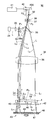
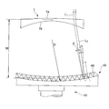
- FIG. 1 is a schematic configuration diagram showing an embodiment of a lens image pickup apparatus according to the present invention.
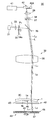
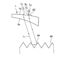
- FIG. 2 is a diagram showing a path of a light beam that passes only through the non-marked portion of the lens to be examined.
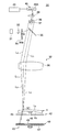
- FIG. 3 is a diagram showing a path of a light beam that passes through the mark.
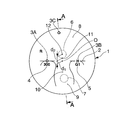
- FIG. 4A is a plan view showing the positional relationship between the marks and the geometric center of the progressive multifocal lens.
- FIG. 4B is a cross-sectional view taken along line AA.
- FIG. 5 is a diagram for explaining mark detection.
- FIG. 6 is a diagram for explaining mark detection.
- FIG. 7 is a diagram for explaining mark detection.
- FIG. 8 is a diagram for explaining mark detection.
- FIG. 9 is a diagram for explaining mark detection.
- FIG. 10 is a view showing an image of a mark obtained by the apparatus of the present invention.
- FIG. 11 is a cross-sectional view of a corner cube prism sheet showing another
- test lens is a divergent progressive multifocal lens and a hidden mark (hereinafter referred to as a mark) formed on the convex surface is detected.
- reference numeral 1 denotes a test lens, which is a circular (for example, 80 mm ⁇ ) plastic progressive multifocal lens whose convex surface 1a is polished.
- Reference numeral 2 denotes a horizontal reference line passing through the geometric center O of the test lens 1, and 3 ⁇ / b> A, 3 ⁇ / b> B, and 3 ⁇ / b> C are marks formed on the convex surface 1 a of the test lens 1.
- These marks 3A, 3B, 3C are formed in the form of minute protrusions (for example, a height of about 2 to 4 ⁇ m).
- the two marks 3A and 3B are formed at two locations on the horizontal reference line 2 that are equidistant (for example, 17 mm) from the geometric center O to the left and right. These marks 3A and 3B are displayed with the same small circle or small circle and letters, and the addition power (external vertex refractive power and near distance of the distance portion) of the lens 1 to be tested is displayed under the marks 3A and 3B.
- a number 4 for displaying the difference in outer apex refractive power of the use part) and an identification mark 5 for displaying the type of lens are also displayed in the form of minute protrusions.
- the number 4 indicating the addition power is displayed as a three-digit number (for example, 300) under the mark 3A located on the ear side when worn.
- FIG. 4 shows a lens for the right eye, and the left mark 3A is indicated by a small circle “ ⁇ ” and the right mark 3B is indicated by a Roman letter “H”.
- the mark 3 ⁇ / b> C is an identification mark for a spectacle store, and is formed of, for example, a round convex mark and is displayed near the outer periphery of the convex surface 1 a.
- a test lens 1 composed of a progressive multifocal lens has a distance power measurement portion 6, a near power measurement portion 7, a distance viewing portion (distance portion) 8, a near viewing portion (near portion) 9 and a power level. It has a continuously changing portion (progressive portion) 10.
- the positions of the distance power measurement portion 6, the near power measurement portion 7 and the eye point 11 of the lens 1 to be examined differ depending on the lens design, but a predetermined reference position away from the geometric center O, for example, the eye point 11 is geometric.
- the distance center 1 is positioned above the academic center O by a predetermined distance d 1 (eg, 2 mm), and the distance center 12 is positioned above the eye point 11 by a predetermined distance d 2 (eg, 4 mm). It has been. Therefore, when the images of the marks 3A and 3B are taken and the position coordinates are calculated by image processing, the positions of the geometric center O and the eye point 11 can be obtained.
- the lens image pickup device 30 includes a light source 31 disposed on the convex surface 1 a side of the test lens 1 and an optical device 32 that guides the light L emitted from the light source 31 to the test lens 1. Yes.
- the light source 31 is used to irradiate the test lens 1 and obtain a clear image of the marks 3A, 3B, 3C, the number 4 indicating the addition power, and the identification mark 5, and a monochromatic point light source is used.
- the monochromatic point light source is used as a broad term including a laser light source that is a point light source and a light source that can be substantially regarded as a point light source, for example, an LED.
- a red semiconductor laser is used as a point light source is shown.
- the optical device 32 includes a condenser lens 33 that condenses the light L emitted from the light source 31, a transmission-type rotational scattering plate 34 disposed in front of the condenser lens 33, and light that has passed through the transmission-type rotational scattering plate 34.
- the transmission type rotary scattering plate 34 is used to remove speckles and fringes, and is a transparent scatterer made of glass or the like.
- the transmission type rotary scattering plate 34 is rotated by a drive motor (not shown) when measuring the mark of the lens 1 to be examined.
- the light L from the light source 31 is configured to be scattered.
- the transmission type rotary scattering plate 34 has a rough surface 34a facing the half mirror 35 and is disposed on the focal position P 1 of the condenser lens 33.
- the half mirror 35 has appropriate transmittance and reflectance, reflects the light L from the light source 31 that has passed through the condenser lens 33 and the transmission-type rotational scattering plate 34 toward the test lens 1, and the test lens 1 side. Light L 2 and L 3 returning from the light is transmitted.
- the collimator lens 36 is disposed in the optical path between the lens 1 to be examined and the half mirror 35, and the light from the light source 31 that has been transmitted through the condenser lens 33 and the transmissive rotation scattering plate 34 and reflected by the half mirror 35. L is converted into parallel light L 1 .
- the test lens 1 is disposed at a focal position P 2 below the collimator lens 36.
- An aperture stop 37, a bandpass filter 38, a re-imaging lens 39, an imaging device 40, and an image processing device 41 are disposed on the opposite side of the half mirror 35 from the lens 1 to be examined.
- the aperture stop 37 is disposed on the focal position P 3 above the collimator lens 36 and limits the diameter of the light beam incident from the collimator lens 36. More specifically, the aperture diameter of the aperture stop 37 is set to be smaller than the beam diameter from the mark C on the convex surface 1a of the lens 1 to be tested and larger than the beam diameter from the non-mark portion.
- the position where the aperture stop 37 is disposed is not limited to the focal position P 3 of the collimator lens 36.
- An equivalent function can be realized by disposing an aperture stop 37 at the exit pupil position of the collimator lens 36.
- the band pass filter 38 transmits only the wavelength band of the light source 31 and cuts extraneous light, and is disposed between the aperture stop 37 and the re-imaging lens 39.
- the re-imaging lens 39 condenses the light L 2 and L 3 that have passed through the bandpass filter 38 on the imaging device 40.
- the imaging device 40 includes a plurality of CCDs 40A that form a light receiving surface, and an image processing device 41 is electrically connected thereto.
- the CCD 40A is disposed at the focal position P 4 of the re-imaging lens 39.
- the focal position P 4 of the re-imaging lens 39 has a conjugate relationship with the convex surface 1a on the collimator lens 36 side of the lens 1 to be examined.
- the lens image pickup device 30 includes a lens holding device 42 and a rotary reflector 43 disposed on the concave surface 1b side of the lens 1 to be examined.
- the lens holding device 42 sucks and fixes the center of the concave surface 1b of the lens 1 to be examined, and includes a transparent plate 45 and a lens suction tube 46 erected at the center of the upper surface of the transparent plate 45.
- the inside of the suction cylinder 46 is evacuated by a vacuum pump so that the center of the concave surface 1b of the lens 1 to be tested is suction fixed to the upper surface of the lens suction cylinder 46.
- the lens adsorption cylinder 46 has a sufficiently small outer diameter (for example, 8 mm ⁇ ) so as not to hinder the projection of the marks 3A, 3B, 3C of the lens 1 to be examined, the number 4 indicating the addition power, and the identification mark 5. ing.
- the rotary reflector 43 retroreflects the light L 1 transmitted through the test lens 1 in the same direction as the incident direction, and includes a rotary plate 47 and a corner cube prism sheet adhered to the surface of the rotary plate 47. 48.
- the corner cube prism sheet 48 is made of plastic having a thickness of about 0.3 mm to 0.5 mm, and a plurality of corner cube prisms (hereinafter also referred to as prisms) 49 are formed on the surface, and the entire surface is transparent. It is protected by a protective film.
- the prism 49 itself is a conventionally known one, and is constituted by three orthogonal total reflection surfaces, thereby reflecting the parallel light L 1 transmitted through the lens 1 in the same direction as the incident direction, that is, retroreflection. It has a function.
- the rotating reflector 43 is configured to be rotated at a high speed (for example, 3400 rpm) by a drive motor (not shown) in order to make the surface brightness and background uniform, similarly to the transmissive rotating scattering plate 34. Yes.
- the light L emitted from the light source 31 exists infinitely, in FIG. 1, only three lights L scattered by the transmission rotation scattering plate 34 are shown, and these lights L are reflected by the half mirror 35, respectively.
- the mark 3C and the two non-mark parts of the lens 1 to be examined are respectively irradiated and retroreflected by the prism 49, and the imaging device
- the four light beams L 2 and L 3 condensed on the 40 CCD 40A are shown, light beams that irradiate and transmit other different parts of the lens 1 to be examined are similarly condensed on the CCD 40A to form an image. Needless to say.
- the lens 1 to be tested is placed on the upper surface opening of the lens suction tube 46 with the convex surface 1a facing up.
- the inside of the lens adsorption cylinder 46 is evacuated by an evacuation apparatus, whereby the lens 1 to be examined is adsorbed and fixed to the upper surface opening of the lens adsorption cylinder 46.
- the light source 31 is turned on to emit light (red laser light) L.
- the light L emitted from the light source 31 is collected by the condenser lens 33, converted to scattered light by passing through the transmission type rotational scattering plate 34, and when reflected on the half mirror 35, it is reflected in the direction of the test lens 1 and is reflected by the collimator lens. is further converted into parallel light L 1 transmits through the 36.
- the parallel light L 1 becomes divergent light by passing through the lens 1 to be measured from the convex surface 1a side to the concave surface 1b side (in the case of a convex lens having convergent refractive power, it becomes convergent light).
- the test lens 1 passes through the concave surface 1b and returns to the convex surface 1a side.
- the reflected light L 2 is diffused when passing through the test lens 1, but the degree of diffusion of the light beam in the non-marked part when passing through the convex surface 1 a made up of the non-marked part is so small that it can be ignored.
- the retroreflected light has a sufficiently small beam diameter. For this reason, the retroreflected light L 2 has almost no loss of light when passing through the aperture stop 37 after re-transmitting the collimator lens 36.
- the retroreflected light L 2 that has passed through the aperture stop 37 passes through the band-pass filter 38 and the re-imaging lens 39 and is condensed on the CCD 40A of the imaging device 40, thereby forming a bright image.
- the parallel light L 1 that has passed through the collimator lens 36 passes through the test lens 1, strikes the prism 49, is retroreflected, and passes through the test lens 1 again.
- the reflected light L 3 diffuses when transmitted through the mark 3C.
- the degree of this diffusion is greater than the retroreflected light L 2 that passes through the non-marked portion.
- the light L 3 transmitted through the mark 3C becomes divergent retroreflected light and returns in the same direction as the incident direction and passes through the collimator lens 36.
- the aperture stop When passing through 37 light is lost.
- the divergent retroreflected light L 3 passes through the band-pass filter 38 and the re-imaging lens 39 and is then condensed on the CCD 40A of the imaging device 40. For this reason, the illuminance of the mark 3C on the CCD 40A is lower than the illuminance of the non-mark part, and the mark 3C can be captured as a clear image.
- the imaging device 40 converts the light received by the CCD 40A into an electrical signal and sends it to the image processing device 41.
- the image processing device 41 processes the image information from the imaging device 40 to identify the delivery eyeglass store by the mark 3C. Further, by receiving the image information of the marks 3A, 3B, etc., the position of the geometric center O of the lens, the position of the eye point 11, etc. are calculated from the position information of these marks 3A, 3B.
- FIG. 5 is a diagram showing the path of the light beam when only the non-mark portion is transmitted and not transmitted through the mark 3C.
- the test lens 1 is a minus lens and the size of the prism 49 is appropriate, the parallel light L 1 incident on the non-marked portion of the convex surface 1 a at the periphery of the test lens 1 is diffused when passing through the test lens 1.
- the light enters the prism 49 it is totally reflected in the same direction as the incident direction.
- the incident point X 1 of the parallel light L 1 light emitted from the reflected convex 1a by the prism 49 (retro-reflected light) and the emission point X 2 of the L 2, slightly offset in the optical axis direction of the lens 1 Yes.
- the incident point X 1 and the exit point X 2 of the convex surface 1a can be regarded as having substantially the same surface curvature, the light L 2 incident on the prism 49 and reflected is parallel to the parallel light L 1. It returns to the original direction as retroreflected light.
- the retroreflected light L 2 passes through the collimator lens 36, the half mirror 35, the aperture stop 37, the band pass filter 38, and the re-imaging lens 39 shown in FIGS. 1 to 3 and then on the CCD 40 A of the imaging device 40.
- a bright image is formed by focusing on the light.
- FIG. 6 is a diagram showing the path of the light beam when passing through the mark 3C and the non-mark part.
- the parallel light L 1 incident on and transmitted through the peripheral edge C of the mark 3C becomes a diffused light L 3 because the surface curvature of the peripheral edge C is completely different from the surface curvature of the non-marked part.
- the prism 49 When incident on the prism 49, it is totally reflected in the same direction as the incident direction. Then, the light passes through the non-marked portion of the lens 1 to be examined, exits from the exit point X 3 , becomes light parallel to the parallel light L 1, and returns to the original direction.
- the light beam has a larger divergence than the retroreflected light L 2 incident on the non-mark portion and emitted from the non-mark portion. Retroreflected light. Therefore, when the divergent retroreflected light L 3 passes through the aperture stop 37 as described above, the loss of light is large, and the illuminance on the CCD 40A is lower than that of the non-marked portion.
- FIG. 7 is a diagram showing the path of light when passing through the non-mark part and passing through the peripheral part of the mark 3C.
- the parallel light L 1 that is incident and transmitted from the point X 4 that is a non-mark portion of the convex surface 1 a but close to the mark 3 C is incident on the prism 49, and is totally reflected in the same direction as the incident direction, and the peripheral portion C of the mark 3 C.
- the light L 1 since the light L 1 has a surface curvature that is completely different from the surface curvature of the non-marked portion, the light L 1 becomes a divergent retroreflected light L 4 that diffuses and has a large light beam diameter. The light is emitted to the convex surface 1a side of the lens 1 to be examined. Then, the divergent retroreflected light L 4 has a large light loss when passing through the aperture stop 37 like the divergent retroreflected light L 3, and the illuminance on the CCD 40A is lower than that of the non-marked portion.
- FIG. 8 is a diagram showing a path of a light beam when entering the center portion of the mark 3C and exiting from a point close to the mark 3C of the non-mark portion.
- the parallel light L 1 incident on the central portion X 5 of the mark 3C and transmitted through the test lens 1 enters the prism 49 and is totally reflected in the same direction as the incident direction, and then passes through the non-mark portion of the test lens 1. transmitted, emitted from the emission point X 6. Since the central portion of the mark 3C has a surface curvature close to the surface curvature of the non-mark portion, the diffusion of the parallel light L 1 by the mark 3 is very slight.
- the light is emitted as retroreflected light L 5 having a small beam diameter from the exit point X 6 to the convex surface 1 a side of the test lens 1.
- the retroreflected light L 5 is not lost by the aperture stop 37, passes through the band-pass filter 38 and the re-imaging lens 39, and is condensed on the CCD 40 A of the image pickup device 40, whereby FIG. As with the retroreflected light L 2 shown in FIG. 5, a bright image is formed.
- FIG. 9 is a diagram showing the path of the light beam when it is incident and transmitted from a point near the mark 3C of the non-mark part and is emitted from the center part of the mark 3C at the time of re-transmission.
- the parallel light L 1 that has entered from the point X 7 near the mark 3C at the non-mark portion of the test lens 1 and transmitted through the test lens 1 enters the prism 49 and is totally reflected in the same direction as the incident direction. Then, the reflected light L 6 is emitted from the central portion X 5 marks 3C.
- the central portion X 5 of the mark 3C has a surface curvature close to the surface curvature of the non-marked portion of the convex surface 1a as described above, even if the reflected light L 6 passes through the central portion X 5 of the mark 3C.
- the light is emitted from the exit point X 5 to the convex surface 1 a side of the test lens 1 as retroreflected light having a small beam diameter. Therefore, the retroreflected light L 6, there is no loss of light due to the aperture stop 37 and is focused on CCD40A transmitted through the band-pass filter 38 and re-imaging lens 39, retroreflected light L 2, L A bright image is formed as in 5 .
- the lens image pickup device 30 uses the corner cube prism 49 to diffuse the light L 2 , L 5 , and L 6 that pass through only the non-marked portion of the convex surface 1a in the round trip.
- divergent retroreflected light having a large degree of diffusion, the light is returned to the convex surface 1a side of the lens 1 to be examined and condensed on the light receiving surface of the CCD 40A.
- the retroreflected light L 2 , L 5 , L 6 and divergent retroreflected light L 3 , L 4 When such retroreflected light L 2 , L 5 , L 6 and divergent retroreflected light L 3 , L 4 are guided to the aperture stop 37, the retroreflected light L 2 , L 5 , L 6 has a sufficiently small beam diameter. Therefore, no light is lost when passing through the aperture stop 37, and the illuminance on the light receiving surface of the CCD 40A can be increased.
- the divergent retroreflected lights L 3 and L 4 the light beam diameter is larger than the aperture diameter of the aperture stop 37, so that the light loss due to the aperture stop 37 is large, and the illuminance of the mark on the light receiving surface of the CCD 40 A decreases.
- the lens image pickup device 30 According to the lens image pickup device 30 according to the present invention, it is possible to obtain a clear mark image having a high contrast as compared with the case where the above-described conventional reflective screen is used. Therefore, image processing is easy, and the design of the image processing circuit can be facilitated.
- FIG. 10 is a view showing an image of the mark 3C obtained by the apparatus of the present invention.
- the image of the mark 3C formed on the CCD 40A of the imaging device 40 becomes a clear image with a dark peripheral edge and a bright central portion, and image processing by the image processing device 41 is easy. To.
- the present invention includes the transmission type rotary scattering plate 34, it is possible to suppress and prevent the generation of speckles and the like by the laser light source. Further, since the brightness of the surface of the corner cube prism sheet 48 serving as the background of the image is averaged by the rotating reflector 43, the image processing can be further facilitated.
- test lens 1 is a colored lens
- an image with clear contrast can be obtained if the mark shape is a shape that can obtain retroreflected light and divergent retroreflected light.
- the CCD40A of the imaging device 40 is set sufficiently smaller than the subject lens 1, a focal length of the focal length (f 1) and the re-imaging lens 39 of the collimator lens 36 (f 2 ) Ratio (horizontal magnification) is sufficiently large, and as a result, the vertical magnification can be sufficiently large, so that the depth of focus can be increased. As an effect of this, it is possible to minimize the blurring when observing the thick lens, and to reduce the shadow of the end surface portion of the minus lens.
- the sample lens from the collimator lens 36 1 is incident obliquely with respect to the end surface portion of the light source 1 and is reflected by the edge surface and reflected by the corner cube prism 49, it does not become effective retroreflected light, and is not condensed on the CCD 40A of the imaging device 40 and is clear.
- the corner cube prism 49 is refracted toward the center of the lens and does not hit the edge surface and passes through the lens. When reflected at, the light becomes retroreflected light, returns to the original direction, and is condensed on the CCD 40A, so that a clear image is obtained. If the conjugate optical system composed of the collimator lens 36 and the re-imaging lens 39 is configured as a double-sided telecentric optical system, even if the thickness fluctuation of the test lens 1 occurs and the blur occurs, the blur occurs. It is possible to obtain the same position of the center of gravity as the image in the case of not doing so.
- the image detection of the mark 3C formed in a convex shape has been described.
- the concave mark has a symmetrical shape with the convex mark, and the peripheral edge of the concave has a completely different surface curvature from the convex surface 1a of the lens 1 to be examined. Since the degree is large, it becomes divergent retroreflected light, and the light transmitted through the central part of the recess becomes retroreflected light because the degree of diffusion is small. For this reason, it is possible to obtain a mark image having a high contrast between the retroreflected light and the divergent retroreflected light and a clear contour shape.
- FIG. 11 is a cross-sectional view of a corner cube prism sheet showing another embodiment of the present invention.
- the corner cube prism sheet 48 is curved in a concave shape on the light source side instead of being formed into a flat plate shape as in the above-described embodiment.
- Other configurations are the same as those of the embodiment shown in FIG.
- the corner cube prism sheet 48 When the corner cube prism sheet 48 is formed in a flat plate shape as indicated by a two-dot chain line, the incident angle ⁇ with respect to the surface of the corner cube prism 49 increases as the light L 1 is farther from the center of the lens 1 to be examined. For this reason, the reflection efficiency of the corner cube prism 49 is lowered. That is, the loss of light increases and the entire image becomes dark. Therefore, when a mark is displayed near the outer periphery of the lens 1 to be examined, it is difficult to obtain a clear image.
- the corner cube prism sheet 48 is curved in a concave shape when viewed from the light source side, the incident angle ⁇ incident on the surface of the corner cube prism 49 even if the light L 1 is far from the center of the lens 1 to be examined. It can be made smaller than in the case of a flat plate. Therefore, the reflection efficiency of the corner cube prism 49 is increased, and the loss of light can be reduced. Thereby, even if the mark is displayed near the outer periphery of the lens 1 to be examined, a clear image can be obtained.
- the light source is a monochromatic point light source.
- the corner cube prism sheet is curved in a concave shape when viewed from the light source side to reduce light loss.
- the corner cube prism sheet is flat, the light transmitted through the test lens is incident on the corner cube prism more obliquely as the light is farther from the center of the test lens. Loss occurs and the reflection efficiency (ratio of incident beam intensity to outgoing beam intensity) decreases. This phenomenon is unfavorable because it causes a decrease in image luminance especially at the outer peripheral portion of the lens to be divergent and lowers the detection sensitivity of marks arranged in the vicinity of the outer peripheral portion.
- the corner cube prism sheet is curved in a concave shape when viewed from the light source side, the light flux that passes through a position far from the center of the test lens having divergence Even so, the angle of incidence on the corner cube prism can be made smaller than in the case of a flat sheet. By doing so, the optical loss can be suppressed to be negligible, and therefore, even when the mark is displayed near the outer periphery of the lens to be examined, the mark can be captured as a clear image.
- the brightness decrease at the outer peripheral portion does not appear as markedly as in a divergent test lens, and the optical path from the test lens to the corner cube prism sheet is convergent. Therefore, even if the corner cube prism sheet is curved concavely, the effective range of light on the prism sheet is limited to the vicinity of the center of the prism sheet, and the inclination angle of the prism sheet in that region is small. Even when the prism sheet is configured as a flat surface, the reduction in reflection efficiency is kept small enough to be ignored.
- the corner cube prism sheet When the corner cube prism sheet is curved in a convex shape when viewed from the light source side, the incident angle of the light that has passed through the outer periphery of the test lens exhibiting a divergent refractive power is incident on the corner cube prism increases. Loss is large, the reflection efficiency is low, and the mark cannot be captured as a clear image.
- the optical device includes a condenser lens that collects the light emitted from the light source, a transmission-type rotational scattering plate that scatters the light transmitted through the condenser lens, and the transmission-type rotational scattering plate.
- a half mirror is provided that guides the transmitted light to the collimator lens, passes through the lens to be examined, reflects against the rotating reflector, retransmits the lens to be examined and the collimator lens, and guides the returning light to the aperture stop.
- the imaging apparatus is provided with a band-pass filter that transmits only the wavelength band of the light source light. Since the band pass filter transmits only the wavelength range of the light source light, it is less affected by disturbance light, and can capture an image with high contrast.
- a preferred embodiment of the present invention includes an image processing device that processes an image picked up by the image pickup device.
Landscapes
- Physics & Mathematics (AREA)
- Analytical Chemistry (AREA)
- General Physics & Mathematics (AREA)
- Chemical & Material Sciences (AREA)
- General Health & Medical Sciences (AREA)
- Biochemistry (AREA)
- Life Sciences & Earth Sciences (AREA)
- Health & Medical Sciences (AREA)
- Immunology (AREA)
- Pathology (AREA)
- Geometry (AREA)
- Testing Of Optical Devices Or Fibers (AREA)
- Investigating Materials By The Use Of Optical Means Adapted For Particular Applications (AREA)
Abstract
光源光(L)をハーフミラー(35)によって反射し、コリメータレンズ(36)によって平行光(L1 )に変換した後、被検レンズ(1)を透過させる。回転反射体(43)に設けたコーナーキューブプリズム(49)は、被検レンズ(1)を透過した光(L1 )を再帰反射する。この再帰反射した反射光(L2 )は、被検レンズ(1)の非マーク部のみを透過する場合、拡散が僅かであるため、光束径が小さい再帰反射光となる。このため、開口絞り(37)による光の損失がなく、CCD(40A)上に集光されると、明るい画像を形成する。一方、被検レンズ(1)のマーク(3C)を透過した光(L3 )は大きく拡散されるため、光束径が大きい発散反射光となり、開口絞り(37)による光損失が大きい。このため、CCD(40A)上に集光されると、照度が低く、暗いマーク画像を形成する。
Description
本発明は、眼鏡レンズの隠しマークやレンズ表面の傷、付着した異物、欠損等の検出、内部欠損(脈理、樹脂流動履歴、ウェルドライン)等の検出、および光学特性の検出等に用いられるレンズ用画像撮像装置に関するものである。
眼鏡レンズ、例えば累進多焦点レンズは、幾何学中心から所定の位置離れた基準位置に隠しマーク(以下、マークという)と呼ばれる凸状(または凹状)のマークが複数個表示されており、これらのマークの位置からレンズの幾何学中心、遠用、近用部の光学中心、アイポイントの位置等を導き出せるように設計されているため、レンズの縁摺り加工時にはこれらのマークの位置からアイポイントの位置を見つけてレンズホルダをアイポイント位置に装着することが行われる。
このような眼鏡レンズに表示されているマークの検出に用いられる装置としては、例えば特開2002-022599号公報に開示されている眼鏡レンズ用画像撮像処理装置が知られている。
この眼鏡レンズ用画像撮像処理装置は、被検レンズの凸面側に光源と、ハーフミラーおよび撮像装置を配設し、凹面側に集光レンズ、結像レンズおよび反射型のスクリーンを配設している。そして、光源からの光によって被検レンズの凸面を照射することにより、凸面に形成されているマークの画像を反射型スクリーンに投影し、このスクリーンで反射した画像を被検レンズの凸面側に戻し、ハーフミラーを介して撮像装置の受光面に結像させ、この画像を画像処理装置によって画像処理することにより、被検レンズの幾何学中心、アイポイントの位置等を算出するようにしている。反射型スクリーンとしては、光を反射させるためにガラス、アルミニウム等の微細な粉を塗布した反射シートを回転板に貼着している。
しかしながら、眼鏡レンズのマークは、刻印等のマーキング技術にばらつきがあり、マークの鮮明度のばらつきとなって判別しにくい場合がある。また、近年マークの表示自体が薄くなってきたり、高屈折力のレンズや着色レンズの普及にともない、マークと、マークが表示されていない部分(以下、非マーク部ともいう)とを通過した光線の輝度差が著しく小さくなってきていることから、従来の装置よりもより一層コントラストを高くすることができ、鮮明な画像が得られる信頼性の高い装置の開発が要請されている。
さらに、被検レンズが、例えば肉厚のバルク材(例えば、マイナス強度の眼鏡レンズ)の場合は、マークが周縁に形成されているとマークに影を発生させる原因となって検出が容易でないため、このようなバルク材に対しても容易に検出が可能な装置の開発が要請されている。
本発明は、上記した従来の問題および要請に応えるべくなされたもので、その目的とするところは、レンズのマークと非マーク部とを透過した光の輝度差が大きくて鮮明な画像を得ることができ、信頼性の高いレンズ用画像撮像装置を提供することにある。
上記目的を達成するために本発明は、光源と、光源から出射した光を平行光に変換して被検レンズの凸面に導くコリメータレンズを含む光学装置と、被検レンズを透過した透過光を反射し被検レンズに戻す回転型反射体と、回転型反射体によって反射され被検レンズおよびコリメータレンズを再透過した反射光を受光する撮像装置と、コリメータレンズと撮像装置との間の光路中に配設された開口絞りと、開口絞りと撮像装置との間に配置された再結像レンズとを備え、回転型反射体は複数のコーナーキューブプリズムにより構成されたシートを有するものである。
本発明において、コーナーキューブプリズムは3つの直交する全反射面を有し、再帰反射機能を有するものであるため、光源から出射した光を入射方向と同一の方向に反射する。被検レンズの凸面に凹状または凸状のマークが表示されている場合、特にマークの周縁部はレンズ表面とは異なる面曲率を有しているので、この周縁部に入射する光束は発散する。また、マークが表示されている以外のレンズ表面(非マーク部)からレンズに入射し、コーナーキューブプリズムによって反射した後、マークの周縁部を透過する光束も、同じく周縁部によって発散する。このため、マークの周縁部を透過して発散し入射方向と同方向に戻る光(以下、このような光を発散再帰反射光という)の輝度は、非マーク部のみを透過して再帰反射する光(以下、このような光を再帰反射光という)と比較して低下する。このことは、すなわち、コリメータレンズによって平行光束に変換された後の光束径が、非マーク部だけを経由した光束がコリメータレンズによって平行光束に変換された後の光束径よりも有意に大きくなることを意味する。したがって、撮像装置の受光面上に被検レンズ面の像を形成させるための再結像レンズの入射瞳径を発散再帰反射光に由来する平行光束径よりも小さく、かつ再帰反射光に由来する平行光束径よりも大きく設定することにより、撮像装置の受光面面上では、マーク部の照度が非マーク部よりも有意に低下することとなり、マークを鮮明な画像として撮像できることとなる。
以下、本発明を図面に示す実施の形態に基づいて詳細に説明する。
本実施の形態は、被検レンズが発散性の累進多焦点レンズであって、その凸面に形成されている隠しマーク(以下、マークと称する)を検出する例について説明する。
本実施の形態は、被検レンズが発散性の累進多焦点レンズであって、その凸面に形成されている隠しマーク(以下、マークと称する)を検出する例について説明する。
図4Aおよび図4Bにおいて、1は被検レンズであり、凸面1aが研磨加工された円形(例えば、80mmφ)のプラスチック製累進多焦点レンズからなる。2は被検レンズ1の幾何学中心Oを通る水平基準線、3A、3B、3Cは被検レンズ1の凸面1aにそれぞれ形成されたマークである。これらのマーク3A、3B、3Cは、微小な突起(例えば、高さ2~4μm程度)の形で形成されている。また、2つのマーク3A、3Bは、水平基準線2上で幾何学中心Oから左右に等距離(例えば17mm)離れた2箇所に形成されている。これらのマーク3A、3Bは、同一の小円または小円と文字で表示され、また、各マーク3A、3Bの下には被検レンズ1の加入度数(遠用部の外側頂点屈折力と近用部の外側頂点屈折力の差)を表示する数字4と、レンズの種類を表示する識別マーク5が同じく微小な突起の形で表示されている。加入度数を表示する数字4は、装用時に耳側に位置するマーク3Aの下に3桁の数字(例えば300)で表示されている。したがって、この3桁の数字が左右どちらのマークの下に表示されているかを知ることにより、左眼用レンズであるか右眼用レンズであるかを識別することができる。この場合、図4においては、右眼用のレンズを示し、左側のマーク3Aを小円「○」で、右側のマーク3Bをローマ字「H」で表示している。マーク3Cは、眼鏡店の識別マークで、例えば丸い凸面状のマークからなり、凸面1aの外周寄りに表示されている。
累進多焦点レンズからなる被検レンズ1は、遠用度数測定部分6、近用度数測定部分7、遠くを見る部分(遠用部)8、近くを見る部分(近用部)9および度数が連続的に変わる部分(累進部)10を有している。
被検レンズ1の遠用度数測定部分6、近用度数測定部分7およびアイポイント11の位置は、レンズ設計によって異なるが、幾何学中心Oから離れた所定の基準位置、例えばアイポイント11は幾何学中心Oの上方に所定距離d1 (例えば、2mm)だけ離れた位置に、また遠用中心12はアイポイント11の位置から上方に所定距離d2 (例えば、4mm)だけ離れた位置に決められている。したがって、マーク3A、3Bの画像を取り込み、画像処理によってその位置座標を算出すると、幾何学中心Oやアイポイント11の位置を求めることができる。
図1において、レンズ用画像撮像装置30は、被検レンズ1の凸面1a側に配設された光源31と、この光源31から出射した光Lを被検レンズ1に導く光学装置32を備えている。
光源31は、被検レンズ1を照射し、マーク3A、3B、3C、加入度数を表示する数字4および識別マーク5の鮮明な画像を得るために用いられるもので、単色点状光源が用いられる。ここで、単色点状光源とは、点光源であるレーザー光源と、実質的に点光源と見なせる光源、例えばLEDを含む広い用語として用いられるものである。なお、本実施例においては、点光源として、赤色半導体レーザーを用いた例を示している。
光学装置32は、光源31から出射した光Lを集光するコンデンサレンズ33と、このコンデンサレンズ33の前方に配置された透過型回転散乱板34と、この透過型回転散乱板34を透過した光Lを被検レンズ1方向に導くハーフミラー35と、このハーフミラー35と被検レンズ1との間に配設され、光源31からの光Lを平行光L1 に変換するコリメータレンズ36とを備えている。
透過型回転散乱板34は、スペックルやフリンジを取り除くために用いられるもので、ガラス等からなる透過性散乱体であり、被検レンズ1のマーク測定時に図示を省略した駆動モータによって回転され、光源31からの光Lを散乱するように構成されている。このため、透過型回転散乱板34は、ハーフミラー35と対向する面34aが粗面に形成されるとともにコンデンサレンズ33の焦点位置P1 上に配設されている。
ハーフミラー35は、適宜な透過率と反射率を有し、コンデンサレンズ33および透過型回転散乱板34を透過した光源31からの光Lを被検レンズ1方向に反射し、被検レンズ1側から戻ってくる光L2 、L3 を透過させる。
コリメータレンズ36は、被検レンズ1とハーフミラー35との間の光路中に配設されており、コンデンサレンズ33および透過型回転散乱板34を透過しハーフミラー35で反射した光源31からの光Lを平行光L1 に変換する。
被検レンズ1は、コリメータレンズ36の下方側の焦点位置P2 に配設されている。
ハーフミラー35の被検レンズ1側とは反対側には、開口絞り37、バンドパスフィルタ38、再結像レンズ39、撮像装置40および画像処理装置41が配設されている。
開口絞り37は、コリメータレンズ36の上方側の焦点位置P3 上に配設されており、コリメータレンズ36から入射する光束の直径を制限している。より具体的には開口絞り37の口径は、被検レンズ1の凸面1a上のマークCからの光束径よりも小さく、かつ非マーク部からの光束径よりも大きく設定されている。ただし、開口絞り37の配設位置はコリメータレンズ36の焦点位置P3 に限定されるものではない。同等の機能は、コリメータレンズ36の射出瞳の位置に開口絞り37を配設すれば実現できる。
バンドパスフィルター38は、光源31の波長帯のみを透過し、外来光をカットするもので、開口絞り37と再結像レンズ39との間に配設されている。
再結像レンズ39は、バンドパスフィルター38を通過した光L2 、L3 を撮像装置40に集光させる。
撮像装置40は、受光面を形成する複数個のCCD40Aを備え、画像処理装置41が電気的に接続されている。CCD40Aは、再結像レンズ39の焦点位置P4 に配置されている。再結像レンズ39の焦点位置P4 は、被検レンズ1のコリメータレンズ36側の凸面1aと共役な関係を有している。
さらに、レンズ用画像撮像装置30は、被検レンズ1の凹面1b側に配設されたレンズ保持装置42および回転型反射体43を備えている。
レンズ保持装置42は、被検レンズ1の凹面1bの中央を吸着し固定するもので、透明板45と、この透明板45の上面中央に立設されたレンズ吸着筒46とを備え、このレンズ吸着筒46の内部を真空ポンプによって真空排気することにより、被検レンズ1の凹面1bの中央をレンズ吸着筒46の上面に吸着固定するように構成されている。レンズ吸着筒46は、被検レンズ1のマーク3A、3B、3C、加入度数を表示する数字4および識別マーク5の投影の妨げにならないように、十分に小さい外径(例えば8mmφ)を有している。
回転型反射体43は、被検レンズ1を透過した光L1 を入射方向と同方向に再帰反射させるもので、回転板47と、この回転板47の表面に貼着されたコーナーキューブプリズムシート48とで構成されている。
コーナーキューブプリズムシート48は、0.3mm~0.5mm程度の厚さのプラスチック製で、表面に複数のコーナーキューブプリズム(以下、プリズムとも云う)49が形成されているとともに、表面全体が透明な保護膜によって保護されている。プリズム49自体は、従来周知のもので、3つの直交する全反射面で構成されることにより、被検レンズ1を透過した平行光L1 を入射方向と同一方向に反射させる機能、すなわち再帰反射機能を有している。そして、回転型反射体43は、透過型回転散乱板34と同様、表面の明るさおよび背景を均一化させるために図示を省略した駆動モータによって高速回転(例えば、3400rpm)するように構成されている。
なお、光源31から出射する光Lは無限に存在するが、図1においては、透過回転散乱板34により散乱した3本の光Lについてのみ示し、これらの光Lがハーフミラー35によってそれぞれ反射し、コリメータレンズ36によってそれぞれ平行光L1 、L1 、L2 に変換された後、被検レンズ1のマーク3Cと2箇所の非マーク部をそれぞれ照射してプリズム49により再帰反射し、撮像装置40のCCD40A上に集光する4本の光線L2 、L3 について示したが、被検レンズ1の他の異なる部位を照射、透過する光線についても同様にCCD40A上に集光し像を結ぶことはいうまでもない。
次に、上記構成からなるレンズ用画像撮像装置30による被検レンズ1のマーク3Cの検出について説明する。
先ず、被検レンズ1をレンズ吸着筒46の上面開口部に凸面1aを上にして載置する。次いで、真空排気装置によってレンズ吸着筒46の内部を真空排気することにより、被検レンズ1をレンズ吸着筒46の上面開口部に吸着固定する。
先ず、被検レンズ1をレンズ吸着筒46の上面開口部に凸面1aを上にして載置する。次いで、真空排気装置によってレンズ吸着筒46の内部を真空排気することにより、被検レンズ1をレンズ吸着筒46の上面開口部に吸着固定する。
次に、光源31を点灯して光(赤色レーザー光)Lを出射させる。光源31から出射した光Lは、コンデンサレンズ33によって集光され、透過型回転散乱板34を透過することにより散乱光に変換され、ハーフミラー35に当たると被検レンズ1方向に反射してコリメータレンズ36を透過することによりさらに平行光L1 に変換される。そして、この平行光L1 は被検レンズ1を凸面1a側から凹面1b側に透過することにより発散光となる(収束性の屈折力を有する凸レンズの場合は収束光となる)。このとき、マークが表示されている以外のレンズ表面(非マーク部)からレンズ1に入射した平行光L1 は、図2に示すようにプリズム49に当たると、入射方向と同方向に反射され、今度は被検レンズ1を凹面1bから透過して凸面1a側に戻る。この反射光L2 は、被検レンズ1を透過するとき拡散するが、非マーク部からなる凸面1aを透過するときの光束の非マーク部における拡散の程度は、無視できるほどきわめて僅かなため、光束径が十分に小さい再帰反射光となる。このため、再帰反射光L2 は、コリメータレンズ36を再透過した後、開口絞り37を通過するとき光の損失がほとんどない。そして、開口絞り37を通過した再帰反射光L2 は、バンドパスフィルター38および再結像レンズ39を透過し撮像装置40のCCD40A上に集光されることにより、明るい画像を形成する。
図3において、コリメータレンズ36を透過した平行光L1 は、被検レンズ1を透過することによりプリズム49に当たって再帰反射し、被検レンズ1を再透過する。このとき、反射光L3 はマーク3Cを透過すると拡散する。この拡散の程度は、前述の非マーク部を透過する再帰反射光L2 に比べて大きい。このため、マーク3Cを透過する光L3 は、発散再帰反射光となって入射方向と同方向に戻りコリメータレンズ36を透過するが、光束径が開口絞り37の口径よりも大きいため、開口絞り37を通過するとき光の損失となる。そして、この発散再帰反射光L3 は、バンドパスフィルター38および再結像レンズ39を透過した後、撮像装置40のCCD40A上に集光される。このため、CCD40A上でのマーク3Cの照度は、非マーク部の照度よりも低く、マーク3Cを鮮明な画像として撮像することができる。
撮像装置40は、CCD40Aによって受光した光を電気信号に変換すると、画像処理装置41に送る。画像処理装置41は、撮像装置40からの画像情報を処理することにより、マーク3Cにより納入眼鏡店先を識別する。また、マーク3A、3B等の画像情報を受け取ることにより、これらマーク3A、3Bの位置情報からレンズの幾何学中心O、アイポイント11の位置等を算出する。
ここで、マーク3Cの検出についてさらに図5~図9に基づいて説明する。
図5は、非マーク部のみを透過し、マーク3Cを透過しない場合の光線の経路を示す図である。被検レンズ1がマイナスレンズで、プリズム49のサイズが適正な場合、被検レンズ1の周縁部で凸面1aの非マーク部に入射した平行光L1 は、被検レンズ1を透過すると拡散光となってプリズム49に入射すると、入射方向と同方向に全反射する。そして、被検レンズ1の凹面1bに入射してレンズを再透過すると凸面1aの非マーク部から出射する。平行光L1 の入射点X1 と、プリズム49によって反射し凸面1aから出射する光(再帰反射光)L2 の出射点X2 とは、被検レンズ1の光軸方向に僅かにずれている。この場合、凸面1aの入射点X1 と出射点X2 とは、略同じ面曲率を有しているとみなせるので、プリズム49に入射して反射する光L2 は平行光L1 と平行な再帰反射光となって元来た方向に戻る。そして、この再帰反射光L2 は、図1~図3に示すコリメータレンズ36、ハーフミラー35、開口絞り37、バンドパスフィルター38および再結像レンズ39を透過した後、撮像装置40のCCD40A上に集光されることにより明るい画像を形成する。
図5は、非マーク部のみを透過し、マーク3Cを透過しない場合の光線の経路を示す図である。被検レンズ1がマイナスレンズで、プリズム49のサイズが適正な場合、被検レンズ1の周縁部で凸面1aの非マーク部に入射した平行光L1 は、被検レンズ1を透過すると拡散光となってプリズム49に入射すると、入射方向と同方向に全反射する。そして、被検レンズ1の凹面1bに入射してレンズを再透過すると凸面1aの非マーク部から出射する。平行光L1 の入射点X1 と、プリズム49によって反射し凸面1aから出射する光(再帰反射光)L2 の出射点X2 とは、被検レンズ1の光軸方向に僅かにずれている。この場合、凸面1aの入射点X1 と出射点X2 とは、略同じ面曲率を有しているとみなせるので、プリズム49に入射して反射する光L2 は平行光L1 と平行な再帰反射光となって元来た方向に戻る。そして、この再帰反射光L2 は、図1~図3に示すコリメータレンズ36、ハーフミラー35、開口絞り37、バンドパスフィルター38および再結像レンズ39を透過した後、撮像装置40のCCD40A上に集光されることにより明るい画像を形成する。
図6は、マーク3Cと非マーク部を透過する場合の光線の経路示す図である。マーク3Cの周縁部Cに入射し透過した平行光L1 は、周縁部Cの面曲率が非マーク部の面曲率と全く異なった面曲率を有しているので、拡散光L3 となってプリズム49に入射すると、入射方向と同方向に全反射する。そして、被検レンズ1の非マーク部を透過して出射点X3 から射出し平行光L1 と平行な光となって元来た方向に戻る。しかし、この光L3 は、マーク3Cの周縁部Cで拡散した拡散光であるため、前述の非マーク部に入射し非マーク部から出射する再帰反射光L2 に比べて光束径が大きい発散再帰反射光となる。このため、この発散再帰反射光L3 は、前述したように開口絞り37を通過するとき、光の損失が大きく、CCD40A上での照度が非マーク部よりも低くなる。
図7は、非マーク部を透過しマーク3Cの周縁部を透過する場合の光線の経路を示す図である。凸面1aの非マーク部ではあるがマーク3Cに近い点X4 より入射して透過した平行光L1 は、プリズム49に入射すると、入射方向と同方向に全反射し、マーク3Cの周縁部Cから出射する。しかし、この光L1 は、周縁部Cの面曲率が非マーク部の面曲率とは全く異なった面曲率を有しているので、拡散して光束径が大きい発散再帰反射光L4 となり、被検レンズ1の凸面1a側に出射する。そして、この発散再帰反射光L4 は、発散再帰反射光L3 と同様に開口絞り37を通過するとき光の損失が大きく、CCD40A上での照度が非マーク部よりも低くなる。
図8は、マーク3Cの中央部に入射し、非マーク部のマーク3Cに近い点から出射する場合の光線の経路を示す図である。マーク3Cの中央部X5 に入射して被検レンズ1を透過した平行光L1 は、プリズム49に入射し、入射方向と同方向に全反射した後、被検レンズ1の非マーク部を透過し、出射点X6 から出射する。マーク3Cの中央部は、非マーク部の面曲率に近い面曲率を有しているため、平行光L1 のマーク3による拡散はきわめて僅かである。このため、光束径が小さい再帰反射光L5 として出射点X6 から被検レンズ1の凸面1a側に出射する。そして、この再帰反射光L5 は、開口絞り37による光の損失がなく、バンドパスフィルター38および再結像レンズ39を透過して撮像装置40のCCD40A上に集光されることにより、図2、図5に示した再帰反射光L2 と同様に明るい画像を形成する。
図9は非マーク部のマーク3Cに近い点から入射して透過し、再透過時にマーク3Cの中央部から出射する場合の光線の経路を示す図である。被検レンズ1の非マーク部でマーク3Cに近い点X7 から入射して被検レンズ1を透過した平行光L1 は、プリズム49に入射し、入射方向と同方向に全反射する。そして、この反射光L6 はマーク3Cの中央部X5 から出射する。マーク3Cの中央部X5 は、上記した通り凸面1aの非マーク部の面曲率に近い面曲率を有しているため、反射光L6 がマーク3Cの中央部X5 を透過しても僅かに拡散するだけで、光束径が小さい再帰反射光として出射点X5 から被検レンズ1の凸面1a側に出射する。したがって、この再帰反射光L6 は、開口絞り37による光の損失がなく、バンドパスフィルター38および再結像レンズ39を透過してCCD40A上に集光されると、再帰反射光L2 、L5 と同様に明るい画像を形成する。
すなわち、本発明に係るレンズ用画像撮像装置30は、コーナーキューブプリズム49を用いることにより、往復路ともに凸面1aの非マーク部のみを透過する光L2 、L5 、L6 については、拡散の程度が僅かな再帰反射光として被検レンズ1の凸面1a側に戻してCCD40Aの受光面上に集光させ、往復路の少なくともいずれか一方においてマーク3Cの周縁部Cを透過する光L3 、L4 については、拡散の程度が大きい発散再帰反射光として被検レンズ1の凸面1a側に戻してCCD40Aの受光面上に集光させるようにしたものである。このような再帰反射光L2 、L5 、L6 と発散再帰反射光L3 、L4 を開口絞り37に導くと、再帰反射光L2 、L5 、L6 は光束径が十分に小さいため、開口絞り37を通過するとき光の損失とならず、CCD40Aの受光面上での照度を高くすることができる。一方、発散再帰反射光L3 、L4 については、光束径が開口絞り37の口径より大きいため、開口絞り37による光の損失が大きく、CCD40Aの受光面上でのマークの照度が低下する。その結果として、本発明に係るレンズ用画像撮像装置30によれば、上述した従来の反射型スクリーンを用いた場合に比べてコントラストが高く鮮明なマーク画像を得ることができる。したがって、画像処理が容易で、画像処理回路の設計を容易にすることができる。
図10は本発明装置によって得られたマーク3Cの画像を示す図である。
図10に示すように、撮像装置40のCCD40A上に結像されたマーク3Cの画像は、周縁部が暗く、中央部が明るい輪郭形状の明瞭な画像となり、画像処理装置41による画像処理を容易にする。
図10に示すように、撮像装置40のCCD40A上に結像されたマーク3Cの画像は、周縁部が暗く、中央部が明るい輪郭形状の明瞭な画像となり、画像処理装置41による画像処理を容易にする。
また、本発明は透過型回転散乱板34を備えているので、レーザー光源によるスペックル等の発生を抑制防止することができる。また、回転型反射体43によって画像の背景となるコーナーキューブプリズムシート48の表面の明るさを平均化させるようにしているので、画像処理を一層容易にすることができる。
また、被検レンズ1が着色レンズであっても、マーク形状が再帰反射光と発散再帰反射光を得られる形状であれば、コントラストの鮮明な画像が得られる。
さらに、本発明においては、撮像装置40のCCD40Aを被検レンズ1よりも十分に小さく設定しているので、コリメータレンズ36の焦点距離(f1 )と再結像レンズ39の焦点距離(f2 )の比(横倍率)が十分に大きくなり、結果として、縦倍率も十分に大きくできるので、焦点深度を深くとることが可能になった。これによる効果としては、厚肉レンズを観察する際のピンボケを最小限にすることができ、マイナスレンズの端面部の影を軽減することができる。
また、本発明においては、コリメータレンズ36によって光源31から出射した光Lを平行光L1 に変換しているが、平行光L1 でない場合には、コリメータレンズ36からの射出光が被検レンズ1の端面部に対して斜めに入射するため、コバ面に当たって反射し、コーナーキューブプリズム49で反射しても、有効な再帰反射光とはならず、撮像装置40のCCD40Aに集光されなくなり鮮明な画像を得ることはできなくなる。これに対して平行光L1 であるとマイナスレンズの端面部に対して大きな入射角で入射するため、レンズ中心方向に屈折してコバ面に当たらず、レンズを透過した後、コーナーキューブプリズム49で反射すると再帰反射光となって元来た方向に戻り、CCD40Aに集光されるため、鮮明な画像が得られる。なお、コリメータレンズ36と再結像レンズ39からなる共役光学系を両側テレセントリック光学系として構成すれば、被検レンズ1の厚さ変動が生じてピンボケが発生した場合であっても、ピンボケが発生していない場合の画像と同じ画像重心位置を得ることができ好適である。
ここで、本実施例においては、凸状に形成したマーク3Cの画像検出について説明したが、凸状に形成されているものに限らず凹状に形成されているマークであっても、全く同様に鮮明な画像が得られるものである。すなわち、凹状のマークは凸状のマークと対称な形状で、凹部の周縁部が被検レンズ1の凸面1aと全く異なる面曲率を有しているため、この周縁部を透過する光は拡散の程度が大きいため発散再帰反射光となり、凹部の中央部を透過する光は拡散の程度が小さいため再帰反射光となる。このため、再帰反射光と発散再帰反射光のコントラストが高く輪郭形状が鮮明なマーク画像を得ることができる。
図11は本発明の他の実施例を示すコーナーキューブプリズムシートの断面図である。
この実施例は、コーナーキューブプリズムシート48を上記した実施例のように平板状に形成する代わりに光源側に凹面状に湾曲させたものである。その他の構成は図1に示した実施例と全く同一である。
この実施例は、コーナーキューブプリズムシート48を上記した実施例のように平板状に形成する代わりに光源側に凹面状に湾曲させたものである。その他の構成は図1に示した実施例と全く同一である。
コーナーキューブプリズムシート48を、2点鎖線で示すように平板状に形成した場合、被検レンズ1の中心から遠い光Ll 程コーナーキューブプリズム49の表面に対する入射角度αが大きくなる。このため、コーナーキューブプリズム49の反射効率は低くなる。すなわち、光の損失が大きくなり、画像全体が暗くなる。したがって、被検レンズ1の外周寄りにマークが表示されている場合は、鮮明な画像が得にくくなる。
そこで、コーナーキューブプリズムシート48を光源側から見て凹面状に湾曲させておくと、被検レンズ1の中心から遠い光Ll であってもコーナーキューブプリズム49の表面に入射する入射角βを平板状の場合に比べて小さくすることができる。したがって、コーナーキューブプリズム49の反射効率が高くなり、光の損失を小さくすることができる。これにより、被検レンズ1の外周寄りに表示されているマークであっても、鮮明な画像を得ることができる。
コーナーキューブプリズムシート48の曲率半径Rが大き過ぎる場合は平板状に近くなるため効果が少なく、小さすぎる場合も被検レンズ1の周辺近傍を通過する光束のコーナーキューブプリズムシート48への入射角が大きくなり光損失を生じることとなるので、レンズ度数に応じて好ましい値に設計することが望ましい。曲率半径Rの好ましい値としては、被検レンズ1の凸面1aに入射する光Ll が光軸に平行な平行光の場合、被検レンズ1の度数をD(ディオプター)、被検レンズ1からコーナーキューブプリズムシート48までの距離をMとすると、度数Dの符号を反転した値の逆数にMを加えた値(R=(-1/D)+M)もしくはこの値に近い値 にすることが望ましい。なお、被検レンズ1の凸面1aに入射する光が平行光でない場合は、入射光の発散角に応じた補正値を加えた値とすればよい。
以上述べたように、本発明の好ましい形態は、光源を単色点状光源としている。
また、本発明の好ましい形態は、コーナーキューブプリズムシートを光源側から見て凹面状に湾曲させ、光損失を少なくしている。すなわち、コーナーキューブプリズムシートが平板状の場合、被検レンズを透過した光は被検レンズの中心から遠い光ほどコーナーキューブプリズムに対して斜めに入射するため、プリズムの幾何的構造に由来する光損失が生じ、反射効率(入射ビームの強度と出射ビームの強度の比)が低くなる。この現象は、とりわけ発散性を呈する被検レンズの外周部において画像輝度を低下させる原因となり、外周部付近に配置されたマークの検出感度を低下させるため好ましくない。
また、本発明の好ましい形態は、コーナーキューブプリズムシートを光源側から見て凹面状に湾曲させ、光損失を少なくしている。すなわち、コーナーキューブプリズムシートが平板状の場合、被検レンズを透過した光は被検レンズの中心から遠い光ほどコーナーキューブプリズムに対して斜めに入射するため、プリズムの幾何的構造に由来する光損失が生じ、反射効率(入射ビームの強度と出射ビームの強度の比)が低くなる。この現象は、とりわけ発散性を呈する被検レンズの外周部において画像輝度を低下させる原因となり、外周部付近に配置されたマークの検出感度を低下させるため好ましくない。
そこで、本発明は、このことの影響を低減するため、コーナーキューブプリズムシートを光源側から見て凹面状に湾曲させているので、発散性を有する被検レンズの中心から遠い位置を通過する光束であってもコーナーキューブプリズムへの入射角を平板状のシートの場合に比べて小さくできる。こうすることで光損失を無視できるほど小さく抑制でき、したがって、被検レンズの外周寄りにマークが表示されている場合であっても、マークを鮮明な画像として撮像することができる。
収束性の屈折力を有する被検レンズにあっては、外周部の輝度低下は発散性を有する被検レンズほど顕著には現れないうえ、被検レンズからコーナーキューブプリズムシートに向かう光路が収束性であるために、コーナーキューブプリズムシートを凹面に湾曲させたとしても、プリズムシート上の光線有効範囲がプリズムシートの中心付近に限定されることとなり、その領域内におけるプリズムシートの傾角が小さい故に、プリズムシートが平面で構成されている場合と比較しても反射効率の低下は無視できるほどに小さく維持される。
コーナーキューブプリズムシートを光源側から見て凸面状に湾曲させた場合は、発散性の屈折力を呈する被検レンズの外周を透過した光のコーナーキューブプリズムに入射する入射角が大きくなるため、光の損失が大きく反射効率が低くなり、マークを鮮明な画像として撮像することができなくなるため好ましくない。
また、本発明の好ましい形態は、光学装置が、光源から出射した光を集光するコンデンサレンズと、このコンデンサレンズを透過した光を散乱させる透過型回転散乱板と、この透過型回転散乱板を透過した光をコリメータレンズに導き、被検レンズを透過した後回転型反射体に当たって反射し被検レンズおよびコリメータレンズを再透過して戻ってくる光を開口絞りに導くハーフミラーを備えている。
また、本発明の好ましい形態は、撮像装置に光源光の波長帯のみを透過するバンドパスフィルターを設けている。
バンドパスフィルターは、光源光の波長域のみを透過するので、外乱光による影響が少なく、コントラストの高い画像の撮像を可能にする。
バンドパスフィルターは、光源光の波長域のみを透過するので、外乱光による影響が少なく、コントラストの高い画像の撮像を可能にする。
さらに、本発明の好ましい形態は、撮像装置によって撮像された画像を処理する画像処理装置を備えている。
Claims (6)
- 光源と、
前記光源から出射した光を平行光に変換して被検レンズの凸面に導くコリメータレンズを含む光学装置と、
前記被検レンズを透過した透過光を反射し前記被検レンズに戻す回転型反射体と、
前記回転型反射体によって反射され前記被検レンズおよび前記コリメータレンズを再透過した反射光を受光する撮像装置と、
前記コリメータレンズと前記撮像装置との間の光路中に配設された開口絞りと、
前記開口絞りと前記撮像装置との間に配置された再結像レンズとを備え、
前記回転型反射体は、複数のコーナーキューブプリズムにより構成されたシートを有することを特徴とするレンズ用画像撮像装置。 - 前記光源は単色点状光源であることを特徴とする請求項1記載のレンズ用画像撮像装置。
- 前記シートは、前記光源の側から見て凹面状に湾曲していることを特徴とする請求項1記載のレンズ用画像撮像装置。
- 前記光学装置は、前記光源から出射した光を集光するコンデンサレンズと、前記コンデンサレンズを透過した光を散乱させる透過型回転散乱板と、前記透過型回転散乱板を透過した光を前記コリメータレンズに導くとともに、前記被検レンズおよび前記コリメータレンズを再透過して戻ってくる光を前記開口絞りに導くハーフミラーとをさらに備えていることを特徴とする請求項1記載のレンズ用画像撮像装置。
- 前記撮像装置は、光源光の波長帯のみを透過するバンドパスフィルターを備えることを特徴とする請求項1記載のレンズ用画像撮像装置。
- 前記撮像装置によって撮像された画像を処理する画像処理装置をさらに備えることを特徴とする請求項1記載のレンズ用画像撮像装置。
Priority Applications (2)
| Application Number | Priority Date | Filing Date | Title |
|---|---|---|---|
| US12/810,144 US20100283999A1 (en) | 2007-12-26 | 2008-12-24 | Lens image sensing apparatus |
| EP08865745.7A EP2239552B1 (en) | 2007-12-26 | 2008-12-24 | Image picking-up device for lens |
Applications Claiming Priority (2)
| Application Number | Priority Date | Filing Date | Title |
|---|---|---|---|
| JP2007334895A JP4906708B2 (ja) | 2007-12-26 | 2007-12-26 | レンズ用画像撮像装置 |
| JP2007-334895 | 2007-12-26 |
Publications (1)
| Publication Number | Publication Date |
|---|---|
| WO2009081928A1 true WO2009081928A1 (ja) | 2009-07-02 |
Family
ID=40801228
Family Applications (1)
| Application Number | Title | Priority Date | Filing Date |
|---|---|---|---|
| PCT/JP2008/073398 WO2009081928A1 (ja) | 2007-12-26 | 2008-12-24 | レンズ用画像撮像装置 |
Country Status (4)
| Country | Link |
|---|---|
| US (1) | US20100283999A1 (ja) |
| EP (1) | EP2239552B1 (ja) |
| JP (1) | JP4906708B2 (ja) |
| WO (1) | WO2009081928A1 (ja) |
Cited By (2)
| Publication number | Priority date | Publication date | Assignee | Title |
|---|---|---|---|---|
| JP2013104780A (ja) * | 2011-11-14 | 2013-05-30 | Shimadzu Corp | 試料支持治具 |
| CN110146257A (zh) * | 2019-05-17 | 2019-08-20 | 中国科学院上海技术物理研究所 | 一种快速测量空间激光载荷光轴变化的装置及方法 |
Families Citing this family (10)
| Publication number | Priority date | Publication date | Assignee | Title |
|---|---|---|---|---|
| US10259607B2 (en) * | 2008-03-04 | 2019-04-16 | Vanrx Pharmasystems Inc. | Aseptic robotic filling system and method |
| US20130242083A1 (en) * | 2010-10-08 | 2013-09-19 | Timothy A. Potts | Retro-reflective imaging |
| US10976572B2 (en) | 2011-12-22 | 2021-04-13 | Carl Zeiss Vision International Gmbh | Method for storing information on a spectacles lens, spectacles lens blank or spectacles lens semi-finished product |
| DE102011089704B4 (de) * | 2011-12-22 | 2020-06-18 | Carl Zeiss Vision International Gmbh | Verfahren zum Speichern von Information auf einem Brillenglas, als Brillenglas-Rohling oder Brillenglas-Halbfabrikat ausgebildeter Glas- oder Kunststoffkörper, Vorrichtung für das Speichern von Information, Verfahren zum Auslesen sowie Lesegerät |
| FR3017964B1 (fr) * | 2014-02-27 | 2016-03-25 | Essilor Int | Instrument optique pour reperer au moins un point caracteristique d'une lentille ophtalmique |
| FR3017963B1 (fr) * | 2014-02-27 | 2016-03-25 | Essilor Int | Instrument optique pour identifier et localiser des microgravures presentes sur une lentille ophtalmique |
| CN104931238B (zh) | 2015-05-18 | 2018-03-30 | 京东方科技集团股份有限公司 | 一种测试透明显示基板透明效果的设备及方法 |
| DE102015115735B3 (de) * | 2015-09-17 | 2017-03-23 | Carl Zeiss Vision International Gmbh | Vorrichtung und Verfahren zum Sichtbarmachen eines Signierzeichens auf einem Brillenglas |
| CN113484322B (zh) * | 2021-07-13 | 2023-01-10 | 天津大学 | 可实时反馈轴向光阱位置的光镊超分辨成像方法和系统 |
| CN118624183A (zh) * | 2024-08-09 | 2024-09-10 | 厦门捷能通光电科技有限公司 | 一种灯珠用透镜光损检测装置及方法 |
Citations (10)
| Publication number | Priority date | Publication date | Assignee | Title |
|---|---|---|---|---|
| JPH085571A (ja) * | 1994-06-21 | 1996-01-12 | New Kurieishiyon:Kk | 検査装置 |
| JPH11118668A (ja) * | 1997-10-16 | 1999-04-30 | Sumitomo Chem Co Ltd | 物体の欠陥の検査方法および検査装置 |
| JP2001524663A (ja) * | 1997-11-20 | 2001-12-04 | トロペル コーポレーション | 透明な面平行プレートを測定するためのすれすれ入射の干渉測定 |
| JP2002162655A (ja) * | 2000-11-27 | 2002-06-07 | Sony Corp | 光学装置 |
| WO2005096074A1 (ja) * | 2004-03-31 | 2005-10-13 | Kabushiki Kaisha Topcon | 治具装着装置 |
| WO2005098521A1 (ja) * | 2004-03-31 | 2005-10-20 | Topcon Corporation | 眼鏡レンズの吸着治具取付装置、及び吸着治具取付位置決定方法 |
| JP2006118935A (ja) * | 2004-10-20 | 2006-05-11 | Hoya Corp | レンズ用撮像装置 |
| JP2006142356A (ja) * | 2004-11-22 | 2006-06-08 | Hoya Corp | マーキング装置及びマーキング方法 |
| JP2006247825A (ja) * | 2005-02-08 | 2006-09-21 | Topcon Corp | 眼鏡レンズの吸着治具取付装置 |
| JP2007526996A (ja) * | 2003-07-17 | 2007-09-20 | カール ツァイス ビジョン ゲーエムベーハー | 眼鏡レンズ上のマークを可視化する方法および装置 |
Family Cites Families (9)
| Publication number | Priority date | Publication date | Assignee | Title |
|---|---|---|---|---|
| US3375754A (en) * | 1964-09-29 | 1968-04-02 | Bausch & Lomb | Lens testing autocollimator |
| JPS604401B2 (ja) * | 1975-01-21 | 1985-02-04 | コニカ株式会社 | 干渉装置 |
| DE29901791U1 (de) * | 1999-02-02 | 2000-07-06 | Novartis Ag, Basel | Linsenmesseinrichtung |
| DE19942998B4 (de) * | 1999-09-09 | 2012-02-09 | Carl Zeiss Jena Gmbh | Mikroskop zur Auf- und Durchlichtmikroskopie |
| CA2413343A1 (en) * | 2002-12-02 | 2004-06-02 | Peter Vokhmin | Method and apparatus for testing optical components |
| FR2853734B1 (fr) * | 2003-04-14 | 2005-05-27 | Tecoptique | Systeme de visualisation de marquages optiques d'un verre ophtalmique, dispositif de tamponnage et procede d'orientation de verres utilisant un tel systeme |
| JP4822318B2 (ja) * | 2005-10-18 | 2011-11-24 | 株式会社トプコン | レンズ吸着治具装着装置に用いられるレンズの位置特定方法およびレンズ吸着治具装着装置 |
| JP2007252402A (ja) * | 2006-03-20 | 2007-10-04 | Topcon Corp | 眼科測定装置 |
| JP4970149B2 (ja) * | 2007-05-31 | 2012-07-04 | 株式会社ニデック | カップ取付け装置 |
-
2007
- 2007-12-26 JP JP2007334895A patent/JP4906708B2/ja not_active Expired - Fee Related
-
2008
- 2008-12-24 EP EP08865745.7A patent/EP2239552B1/en not_active Not-in-force
- 2008-12-24 WO PCT/JP2008/073398 patent/WO2009081928A1/ja active Application Filing
- 2008-12-24 US US12/810,144 patent/US20100283999A1/en not_active Abandoned
Patent Citations (10)
| Publication number | Priority date | Publication date | Assignee | Title |
|---|---|---|---|---|
| JPH085571A (ja) * | 1994-06-21 | 1996-01-12 | New Kurieishiyon:Kk | 検査装置 |
| JPH11118668A (ja) * | 1997-10-16 | 1999-04-30 | Sumitomo Chem Co Ltd | 物体の欠陥の検査方法および検査装置 |
| JP2001524663A (ja) * | 1997-11-20 | 2001-12-04 | トロペル コーポレーション | 透明な面平行プレートを測定するためのすれすれ入射の干渉測定 |
| JP2002162655A (ja) * | 2000-11-27 | 2002-06-07 | Sony Corp | 光学装置 |
| JP2007526996A (ja) * | 2003-07-17 | 2007-09-20 | カール ツァイス ビジョン ゲーエムベーハー | 眼鏡レンズ上のマークを可視化する方法および装置 |
| WO2005096074A1 (ja) * | 2004-03-31 | 2005-10-13 | Kabushiki Kaisha Topcon | 治具装着装置 |
| WO2005098521A1 (ja) * | 2004-03-31 | 2005-10-20 | Topcon Corporation | 眼鏡レンズの吸着治具取付装置、及び吸着治具取付位置決定方法 |
| JP2006118935A (ja) * | 2004-10-20 | 2006-05-11 | Hoya Corp | レンズ用撮像装置 |
| JP2006142356A (ja) * | 2004-11-22 | 2006-06-08 | Hoya Corp | マーキング装置及びマーキング方法 |
| JP2006247825A (ja) * | 2005-02-08 | 2006-09-21 | Topcon Corp | 眼鏡レンズの吸着治具取付装置 |
Cited By (3)
| Publication number | Priority date | Publication date | Assignee | Title |
|---|---|---|---|---|
| JP2013104780A (ja) * | 2011-11-14 | 2013-05-30 | Shimadzu Corp | 試料支持治具 |
| CN110146257A (zh) * | 2019-05-17 | 2019-08-20 | 中国科学院上海技术物理研究所 | 一种快速测量空间激光载荷光轴变化的装置及方法 |
| CN110146257B (zh) * | 2019-05-17 | 2024-02-20 | 中国科学院上海技术物理研究所 | 一种快速测量空间激光载荷光轴变化的装置及方法 |
Also Published As
| Publication number | Publication date |
|---|---|
| EP2239552A1 (en) | 2010-10-13 |
| JP4906708B2 (ja) | 2012-03-28 |
| EP2239552A4 (en) | 2015-07-08 |
| US20100283999A1 (en) | 2010-11-11 |
| EP2239552B1 (en) | 2018-09-19 |
| JP2009156702A (ja) | 2009-07-16 |
Similar Documents
| Publication | Publication Date | Title |
|---|---|---|
| JP4906708B2 (ja) | レンズ用画像撮像装置 | |
| TWI427286B (zh) | 用於檢測玻璃板之裝置及方法 | |
| JP5388543B2 (ja) | 外観検査装置 | |
| US20110317156A1 (en) | Inspection device for defect inspection | |
| US7796276B2 (en) | Apparatus and method for examining a curved surface | |
| JPS58219441A (ja) | 凸面体の表面欠陥検査装置 | |
| JP2013137531A (ja) | 眼鏡レンズ上のシグネチャマークを可視化する方法及び装置 | |
| JP2007171149A (ja) | 表面欠陥検査装置 | |
| US6636308B1 (en) | Apparatus for measuring characteristics of optical angle | |
| JP3617805B2 (ja) | 眼鏡レンズ用画像撮像処理装置 | |
| JP6385974B2 (ja) | 全反射吸収スペクトル測定用光学器具、および、測定装置 | |
| TW200525142A (en) | Method and device for detecting defects of glass plate | |
| US6184977B1 (en) | Inspection method and inspection device | |
| JP2005316436A (ja) | 眼鏡レンズへの自動装着装置 | |
| TWI250517B (en) | Appearance inspector | |
| JP3417736B2 (ja) | 光学部材検査装置 | |
| KR101447857B1 (ko) | 렌즈 모듈 이물 검사 시스템 | |
| JP3388285B2 (ja) | 検査装置 | |
| JP2821460B2 (ja) | 透明基板の傷検査装置 | |
| JP4514036B2 (ja) | レンズ用撮像装置 | |
| JP3417972B2 (ja) | レンズ検査装置及びその検査方法 | |
| JPS6313446Y2 (ja) | ||
| CN211263958U (zh) | 高灵敏度透明物体脉理和表面缺陷观测装置 | |
| JP2000295639A (ja) | 固体撮像素子検査用照明装置及びそれに用いる調整工具 | |
| JP4563736B2 (ja) | 吸着治具の装着装置 |
Legal Events
| Date | Code | Title | Description |
|---|---|---|---|
| 121 | Ep: the epo has been informed by wipo that ep was designated in this application |
Ref document number: 08865745 Country of ref document: EP Kind code of ref document: A1 |
|
| WWE | Wipo information: entry into national phase |
Ref document number: 2008865745 Country of ref document: EP |
|
| WWE | Wipo information: entry into national phase |
Ref document number: 12810144 Country of ref document: US |
|
| NENP | Non-entry into the national phase |
Ref country code: DE |