WO2009081844A1 - 医療用長尺体、その製造方法およびその製造装置 - Google Patents
医療用長尺体、その製造方法およびその製造装置 Download PDFInfo
- Publication number
- WO2009081844A1 WO2009081844A1 PCT/JP2008/073123 JP2008073123W WO2009081844A1 WO 2009081844 A1 WO2009081844 A1 WO 2009081844A1 JP 2008073123 W JP2008073123 W JP 2008073123W WO 2009081844 A1 WO2009081844 A1 WO 2009081844A1
- Authority
- WO
- WIPO (PCT)
- Prior art keywords
- mold roller
- mold
- elongated body
- medical
- guide wire
- Prior art date
Links
- 238000004519 manufacturing process Methods 0.000 title claims description 51
- 238000000034 method Methods 0.000 title claims description 17
- 229920005989 resin Polymers 0.000 claims abstract description 76
- 239000011347 resin Substances 0.000 claims abstract description 76
- 239000000463 material Substances 0.000 claims description 15
- 238000010438 heat treatment Methods 0.000 claims description 13
- 238000003825 pressing Methods 0.000 claims description 5
- 230000001154 acute effect Effects 0.000 claims description 4
- 239000011737 fluorine Substances 0.000 claims description 4
- 229910052731 fluorine Inorganic materials 0.000 claims description 4
- 239000000758 substrate Substances 0.000 claims 6
- PXGOKWXKJXAPGV-UHFFFAOYSA-N Fluorine Chemical compound FF PXGOKWXKJXAPGV-UHFFFAOYSA-N 0.000 claims 2
- 238000009826 distribution Methods 0.000 abstract description 7
- 239000010410 layer Substances 0.000 description 53
- 238000012545 processing Methods 0.000 description 20
- 238000012986 modification Methods 0.000 description 9
- 230000004048 modification Effects 0.000 description 9
- 238000010586 diagram Methods 0.000 description 8
- 208000031481 Pathologic Constriction Diseases 0.000 description 6
- 208000037804 stenosis Diseases 0.000 description 6
- 230000036262 stenosis Effects 0.000 description 6
- 239000011521 glass Substances 0.000 description 5
- 239000002184 metal Substances 0.000 description 5
- 229910052751 metal Inorganic materials 0.000 description 5
- 241000135309 Processus Species 0.000 description 4
- 210000004204 blood vessel Anatomy 0.000 description 4
- 239000011247 coating layer Substances 0.000 description 4
- 230000000694 effects Effects 0.000 description 4
- 239000013618 particulate matter Substances 0.000 description 3
- 230000008569 process Effects 0.000 description 3
- 239000002356 single layer Substances 0.000 description 3
- 238000009751 slip forming Methods 0.000 description 3
- IJGRMHOSHXDMSA-UHFFFAOYSA-N Atomic nitrogen Chemical compound N#N IJGRMHOSHXDMSA-UHFFFAOYSA-N 0.000 description 2
- YCKRFDGAMUMZLT-UHFFFAOYSA-N Fluorine atom Chemical compound [F] YCKRFDGAMUMZLT-UHFFFAOYSA-N 0.000 description 2
- HZEWFHLRYVTOIW-UHFFFAOYSA-N [Ti].[Ni] Chemical compound [Ti].[Ni] HZEWFHLRYVTOIW-UHFFFAOYSA-N 0.000 description 2
- 229920006127 amorphous resin Polymers 0.000 description 2
- 238000002399 angioplasty Methods 0.000 description 2
- 239000011248 coating agent Substances 0.000 description 2
- 238000000576 coating method Methods 0.000 description 2
- 230000009477 glass transition Effects 0.000 description 2
- 238000003780 insertion Methods 0.000 description 2
- 230000037431 insertion Effects 0.000 description 2
- 238000002844 melting Methods 0.000 description 2
- 230000008018 melting Effects 0.000 description 2
- 229910001000 nickel titanium Inorganic materials 0.000 description 2
- 239000004810 polytetrafluoroethylene Substances 0.000 description 2
- 229920001343 polytetrafluoroethylene Polymers 0.000 description 2
- 239000002344 surface layer Substances 0.000 description 2
- 230000003746 surface roughness Effects 0.000 description 2
- 238000011282 treatment Methods 0.000 description 2
- 229910000531 Co alloy Inorganic materials 0.000 description 1
- 241000219171 Malpighiales Species 0.000 description 1
- 239000004952 Polyamide Substances 0.000 description 1
- 239000004698 Polyethylene Substances 0.000 description 1
- 239000004642 Polyimide Substances 0.000 description 1
- 238000002583 angiography Methods 0.000 description 1
- 238000013459 approach Methods 0.000 description 1
- QVGXLLKOCUKJST-UHFFFAOYSA-N atomic oxygen Chemical compound [O] QVGXLLKOCUKJST-UHFFFAOYSA-N 0.000 description 1
- 230000004323 axial length Effects 0.000 description 1
- 239000010953 base metal Substances 0.000 description 1
- 238000005094 computer simulation Methods 0.000 description 1
- 239000011162 core material Substances 0.000 description 1
- 238000007887 coronary angioplasty Methods 0.000 description 1
- 210000004351 coronary vessel Anatomy 0.000 description 1
- 238000005520 cutting process Methods 0.000 description 1
- 238000001514 detection method Methods 0.000 description 1
- 230000002526 effect on cardiovascular system Effects 0.000 description 1
- 239000003822 epoxy resin Substances 0.000 description 1
- 238000011156 evaluation Methods 0.000 description 1
- 230000006870 function Effects 0.000 description 1
- 239000007789 gas Substances 0.000 description 1
- 229920006015 heat resistant resin Polymers 0.000 description 1
- 238000007689 inspection Methods 0.000 description 1
- 239000007788 liquid Substances 0.000 description 1
- 229910052757 nitrogen Inorganic materials 0.000 description 1
- 239000001301 oxygen Substances 0.000 description 1
- 229910052760 oxygen Inorganic materials 0.000 description 1
- 210000005259 peripheral blood Anatomy 0.000 description 1
- 239000011886 peripheral blood Substances 0.000 description 1
- 239000005011 phenolic resin Substances 0.000 description 1
- 230000000704 physical effect Effects 0.000 description 1
- 229920002492 poly(sulfone) Polymers 0.000 description 1
- 229920002647 polyamide Polymers 0.000 description 1
- 229920000647 polyepoxide Polymers 0.000 description 1
- -1 polyethylene Polymers 0.000 description 1
- 229920000573 polyethylene Polymers 0.000 description 1
- 229920001721 polyimide Polymers 0.000 description 1
- 229920001296 polysiloxane Polymers 0.000 description 1
- 229920002635 polyurethane Polymers 0.000 description 1
- 239000004814 polyurethane Substances 0.000 description 1
- 238000002360 preparation method Methods 0.000 description 1
- 210000001147 pulmonary artery Anatomy 0.000 description 1
- 230000035807 sensation Effects 0.000 description 1
- 239000010935 stainless steel Substances 0.000 description 1
- 229910001256 stainless steel alloy Inorganic materials 0.000 description 1
- 239000004753 textile Substances 0.000 description 1
- 229920001187 thermosetting polymer Polymers 0.000 description 1
- 238000012546 transfer Methods 0.000 description 1
- 238000009827 uniform distribution Methods 0.000 description 1
- 230000002485 urinary effect Effects 0.000 description 1
Images


Classifications
-
- A—HUMAN NECESSITIES
- A61—MEDICAL OR VETERINARY SCIENCE; HYGIENE
- A61M—DEVICES FOR INTRODUCING MEDIA INTO, OR ONTO, THE BODY; DEVICES FOR TRANSDUCING BODY MEDIA OR FOR TAKING MEDIA FROM THE BODY; DEVICES FOR PRODUCING OR ENDING SLEEP OR STUPOR
- A61M25/00—Catheters; Hollow probes
- A61M25/0009—Making of catheters or other medical or surgical tubes
-
- A—HUMAN NECESSITIES
- A61—MEDICAL OR VETERINARY SCIENCE; HYGIENE
- A61M—DEVICES FOR INTRODUCING MEDIA INTO, OR ONTO, THE BODY; DEVICES FOR TRANSDUCING BODY MEDIA OR FOR TAKING MEDIA FROM THE BODY; DEVICES FOR PRODUCING OR ENDING SLEEP OR STUPOR
- A61M25/00—Catheters; Hollow probes
- A61M25/0043—Catheters; Hollow probes characterised by structural features
-
- A—HUMAN NECESSITIES
- A61—MEDICAL OR VETERINARY SCIENCE; HYGIENE
- A61M—DEVICES FOR INTRODUCING MEDIA INTO, OR ONTO, THE BODY; DEVICES FOR TRANSDUCING BODY MEDIA OR FOR TAKING MEDIA FROM THE BODY; DEVICES FOR PRODUCING OR ENDING SLEEP OR STUPOR
- A61M25/00—Catheters; Hollow probes
- A61M25/01—Introducing, guiding, advancing, emplacing or holding catheters
- A61M25/09—Guide wires
-
- A—HUMAN NECESSITIES
- A61—MEDICAL OR VETERINARY SCIENCE; HYGIENE
- A61M—DEVICES FOR INTRODUCING MEDIA INTO, OR ONTO, THE BODY; DEVICES FOR TRANSDUCING BODY MEDIA OR FOR TAKING MEDIA FROM THE BODY; DEVICES FOR PRODUCING OR ENDING SLEEP OR STUPOR
- A61M25/00—Catheters; Hollow probes
- A61M25/0043—Catheters; Hollow probes characterised by structural features
- A61M2025/006—Catheters; Hollow probes characterised by structural features having a special surface topography or special surface properties, e.g. roughened or knurled surface
-
- A—HUMAN NECESSITIES
- A61—MEDICAL OR VETERINARY SCIENCE; HYGIENE
- A61M—DEVICES FOR INTRODUCING MEDIA INTO, OR ONTO, THE BODY; DEVICES FOR TRANSDUCING BODY MEDIA OR FOR TAKING MEDIA FROM THE BODY; DEVICES FOR PRODUCING OR ENDING SLEEP OR STUPOR
- A61M25/00—Catheters; Hollow probes
- A61M25/01—Introducing, guiding, advancing, emplacing or holding catheters
- A61M25/09—Guide wires
- A61M2025/09058—Basic structures of guide wires
- A61M2025/09075—Basic structures of guide wires having a core without a coil possibly combined with a sheath
-
- A—HUMAN NECESSITIES
- A61—MEDICAL OR VETERINARY SCIENCE; HYGIENE
- A61M—DEVICES FOR INTRODUCING MEDIA INTO, OR ONTO, THE BODY; DEVICES FOR TRANSDUCING BODY MEDIA OR FOR TAKING MEDIA FROM THE BODY; DEVICES FOR PRODUCING OR ENDING SLEEP OR STUPOR
- A61M25/00—Catheters; Hollow probes
- A61M25/01—Introducing, guiding, advancing, emplacing or holding catheters
- A61M25/09—Guide wires
- A61M2025/09108—Methods for making a guide wire
-
- A—HUMAN NECESSITIES
- A61—MEDICAL OR VETERINARY SCIENCE; HYGIENE
- A61M—DEVICES FOR INTRODUCING MEDIA INTO, OR ONTO, THE BODY; DEVICES FOR TRANSDUCING BODY MEDIA OR FOR TAKING MEDIA FROM THE BODY; DEVICES FOR PRODUCING OR ENDING SLEEP OR STUPOR
- A61M25/00—Catheters; Hollow probes
- A61M25/01—Introducing, guiding, advancing, emplacing or holding catheters
- A61M25/09—Guide wires
- A61M2025/09133—Guide wires having specific material compositions or coatings; Materials with specific mechanical behaviours, e.g. stiffness, strength to transmit torque
-
- A—HUMAN NECESSITIES
- A61—MEDICAL OR VETERINARY SCIENCE; HYGIENE
- A61M—DEVICES FOR INTRODUCING MEDIA INTO, OR ONTO, THE BODY; DEVICES FOR TRANSDUCING BODY MEDIA OR FOR TAKING MEDIA FROM THE BODY; DEVICES FOR PRODUCING OR ENDING SLEEP OR STUPOR
- A61M25/00—Catheters; Hollow probes
- A61M25/0043—Catheters; Hollow probes characterised by structural features
- A61M25/0045—Catheters; Hollow probes characterised by structural features multi-layered, e.g. coated
Definitions
- the present invention relates to a medical elongated body, a manufacturing method thereof, and a manufacturing apparatus thereof.
- a variety of medical elongated bodies such as guide wires and catheters are used for various purposes such as biological examinations and treatments.
- PTCA Percutaneous Transluminal Coronary Angioplasty
- PTCA Percutaneous Transluminal Coronary Angioplasty
- the catheter is used to guide the guide wire to a target site in the living body.
- the guide wire used for PTCA is inserted from the tip of the balloon catheter to the vicinity of the stenosis of the coronary artery, which is the target site, together with the balloon catheter.
- the stenosis only the thin guide wire passes through the stenosis, and the balloon catheter is guided while the stenosis is expanded.
- PTA Percutaneous Transluminal Angioplasty
- a guide wire is used in the same way as PTCA for reopening of stenosis / occlusion of peripheral blood vessels such as femoral, iriac, linal, and shunt. Guides the balloon catheter to the stenosis.
- the guide wire is inserted into the lumen of the catheter or the lumen of the endoscope, and is used by moving or rotating in the longitudinal direction, but the sliding resistance (friction resistance) is small at that time. Is preferable for improving operability.
- a guide wire in which a fluororesin coating layer to which particulate matter is added is formed on the surface of a metal wire. See FIG. 1 and FIG. 2 in US Patent Publication No. 2006-0073264 A1. According to this guide wire, a plurality of protrusions are formed on the surface of the fluororesin coating layer by the particulate matter. Therefore, the contact area with the inner surface of the catheter is reduced, and the frictional resistance is also reduced.
- a guide wire is also proposed in which a plurality of metal wires are bundled and twisted to form a fluororesin coating layer on the surface. See FIG. 2 of US Patent No. US6251085 B1.
- the base metal wire itself is processed instead of the fluororesin coating layer on the surface. Therefore, the durability as a guide wire is weakened.
- An object of the present invention is to provide a long body having protrusions with a uniform distribution on the surface while maintaining high durability.
- the present invention aims to provide a long body having a uniform smooth surface throughout.
- the medical long body of the present invention was uniformly distributed on the surface of the elongated base material, the resin layer coated or integrally formed on at least a part of the surface of the base material, and the resin layer A plurality of protrusions.
- the medical elongated body of the present invention comprises an elongated base material, and a resin layer that is coated or integrally formed on at least a part of the surface of the base material and has a plurality of protrusions on the surface.
- the SMD is 0.22 to 0.48 ⁇ m over the entire surface of the resin layer.
- the method for manufacturing a medical elongated body includes the following steps.
- a long body having a surface formed of a resin is prepared.
- a second mold roller that is rotatable about a second rotation axis that crosses the first axis and that has a concave portion formed on a cylindrical side surface is disposed so as to sandwich the long body. While rotating the first mold roller and the second mold roller and feeding the long body in the axial direction, the convex surface pattern corresponding to the concave portions of the first mold roller and the second mold roller is formed on the long body. To form.
- the manufacturing method of a medical elongate body includes the following steps.
- a long body having a surface formed of a resin is prepared.
- a pair of mold rollers that are rotatable about a rotation axis perpendicular to the axial direction of the long body and in which a concave portion is formed on a cylindrical side surface are arranged so as to sandwich the long body.
- a pair of mold rollers are rotated to feed a long body in the axial direction, and a convex surface pattern corresponding to a concave portion of the mold roller is formed on the long body.
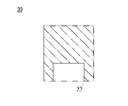
- FIG. 1 is a schematic view showing a guide wire inserted through a catheter
- FIGS. 2A and 2B are partial sectional views of the catheter.
- 2A is a cross-sectional view of the catheter cut in parallel to the axial direction
- FIG. 2B is a cross-sectional view of the catheter cut perpendicular to the axial direction.
- the guide wire 10 can pass through a lumen formed in the catheter 20 in the axial direction.
- the operator can move the guide wire 10 back and forth in the catheter 20 by holding the proximal end of the guide wire 10 and moving it back and forth.
- the catheter 20 is composed of a flexible tubular body, and as shown in FIGS. 2A and 2B, a lumen 22 is formed at almost the center of the catheter 20 over the entire length of the catheter body.
- the catheter 20 is inserted into a living body, for example, a blood vessel, and is guided to the affected area by the guide wire 10.
- catheters such as angiographic catheters, microcatheters, balloon catheters, heart catheters, pulmonary artery catheters, urinary catheters, and the like. Any common catheter may be used.
- a detailed description of the function of the catheter is omitted.
- FIG. 3 is a cross-sectional view of the guide wire
- FIG. 4 is an enlarged view showing the shape of the surface of the guide wire
- FIG. 5 is a schematic diagram showing the guide wire processing device
- FIG. 6 is a diagram showing the type of the processing device
- FIG. It is a figure which shows the mode of the resin layer which deform
- the guide wire 10 is a medical instrument that is advanced in advance in a blood vessel in order to guide a catheter inserted into a blood vessel of a living body to a target site (affected site), for example.
- the guide wire 10 can be inserted through a lumen formed in the axial direction inside the catheter.
- the catheter can travel within the blood vessel along the guidewire 10.
- the guide wire 10 has a multilayer structure as shown in FIG.
- the guide wire 10 includes a single linear element wire 12 made of a single material, for example, nickel titanium, and a resin layer 14 made of resin and coated on the surface of the element wire (base material) 12.
- the resin layer 14 includes a base layer 140 that covers the strands 12 in close contact, and a fluororesin layer 142 that covers the base layer 140 and is made of a resin containing fluorine.
- the material of the wire 12 include stainless steel and cobalt alloy instead of nickel titanium.
- the underlayer 140 of the resin layer 14 is preferably a heat resistant resin or a thermosetting resin, and examples thereof include polysulfone, polyimide, epoxy resin, and phenol resin.
- the fluororesin layer 142 is made of, for example, PTFE, PFA, or FEP.
- the surface layer of the underlayer 140 can be formed of polyamide, polyethylene, silicone, or polyurethane instead of the fluororesin.
- the resin layer 14 may be a single layer.
- the resin layer 14 may be formed by coating, but a heat-shrinkable tube made of a fluororesin such as PTFE, PFA, or FEP may be contracted to the wire 12.
- the guide wire 10 has at least a surface made of resin.
- a plurality of fine protrusions 144 are formed on the surface of the fluororesin layer 142.
- the protrusions 144 are uniformly distributed on the surface of the resin layer 14 as shown in FIG.
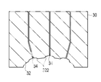
- the processing apparatus shown in FIG. 5 has a pair of molds 30 that are arranged symmetrically with the guide wire 10 in between. As shown in FIG. 6, each mold 30 has a recess 32.
- the processing apparatus causes the mold 30 to approach from both sides of the guide wire 10 so that the surface on which the recess 32 is formed is pressed against the guide wire 10. For example, when the diameter of the guide wire 10 is 0.014 inch, the pressure when approaching is 300 to 1200 gf, and preferably 400 to 600 gf.
- the mold 30 is heated below the melting point of the resin layer 14. By heating, the resin layer 14 on the surface of the guide wire 10 is easily deformed, and the protrusion 144 is formed.
- the temperature for heating the mold 30 is, for example, 80 degrees to 260 degrees, and preferably 180 degrees to 220 degrees. However, since the melting point varies depending on the components constituting the resin layer 14, the heating temperature can be appropriately changed according to the resin.
- the recess 32 of the mold 30 is not formed with a passage for escaping air at the bottom, so-called air escape. Therefore, as shown in FIG. 7, the resin of the resin layer 14 (fluorine resin layer 142) flows only to the extent that the recesses 32 are incompletely filled. Therefore, as shown in the drawing, the upper surface of the protrusion 144 is not mainly flat, and finer irregularities 146 are formed. On the other hand, an air escape may be formed in the recess 32 of the mold 30. In this case, since air escapes, the resin of the resin layer 14 flows so as to completely fill the concave portion 32 of the mold 30. Thereby, the protrusion 144 having a flat upper surface can be formed.
- the processing apparatus performs the above pressing operation while rotating the guide wire 10 until the protrusion 144 is formed on the entire circumference of the guide wire 10, that is, until the guide wire 10 is rotated approximately 180 degrees.
- the processing apparatus feeds the guide wire 10 by a predetermined amount by a feeding device (not shown) to form the projections 144 on the entire circumference.
- the predetermined amount is, for example, a distance at which the formed protrusion 144 is not broken when the mold 30 is processed next. By repeating this, protrusions are formed over the entire circumference of the guide wire 10.
- an elliptical projection 144 is formed on the surface of the guide wire 10 as shown in FIG.
- the shape of the protrusion 144 viewed from the top surface is not limited to an ellipse. Any shape such as a circle or polygon may be used.
- the plurality of protrusions 144 are formed uniformly distributed on the surface of the guide wire 10.
- the size and distribution of the protrusions 144 are determined so that the SMD is 0.26 to 0.48 ⁇ m, preferably 0.38 to 0.46 ⁇ m.
- SMD represents an average deviation of the surface roughness (Mean Deviation of Surface Geometric Roughness), which can be measured by the method described later. If the SMD exceeds 0.48 ⁇ m, the surface unevenness becomes rough and the friction coefficient increases, so that the insertion resistance during use becomes too high. On the other hand, even if the SMD is smaller than 0.26 ⁇ m, the unevenness of the surface is reduced, and the friction coefficient is increased, so that the insertion resistance during use is increased.
- the SMD is more preferably 0.38 to 0.42 ⁇ m.
- the size and distribution of the protrusions 144 for obtaining a desired SMD can be calculated by computer simulation, for example. As another method, optimal parameters may be determined by trial and error.
- the guide wire 10 is prototyped by adjusting the size of the concave portion 32 of the mold 30, the interval at which the mold is pressed, the pressing force, and the like, and the SMD of the surface of the completed guide wire 10 is measured.
- parameters such as the size of the concave portion 32 of the mold 30, the interval at which the mold is pressed, and the pressing force are recorded. By using the recorded parameters for subsequent processing, the size and distribution of the protrusions 144 can be uniquely determined.
- SMD is a friction tester KES-SE (trade name) manufactured by Kato Tech Co., Ltd., which conforms to the method described in “Standardization and Analysis of Texture Evaluation” (Katsuo Kawabata (Author), 1980, Japan Textile Machinery Society 2nd Edition). Measured by
- T detection thickness ( ⁇ m)
- T Average thickness ( ⁇ m)
- x Movement distance (20 mm) (effect)
- the plurality of protrusions 144 that are uniformly distributed are formed on the surface of the resin layer 14. Therefore, when the guide wire 10 is inserted through the catheter 20, the contact area with the inner surface of the catheter 20 is reduced. A low sliding resistance is obtained uniformly over the entire resin layer 14 of the guide wire 10.
- the plurality of projections 144 that are uniformly distributed are formed on the surface of the resin layer 14 so that the SMD is 0.22 to 0.48 ⁇ m.
- a low sliding resistance is obtained uniformly over the entire resin layer 14 of the guide wire 10. Since the SMD of the guide wire 10 is 0.22 to 0.48 ⁇ m, the operator can work with almost the same feeling regardless of which guide wire 10 is used.
- the density of the protrusions 144 preferably present 15 or more in 0.04 mm 2, 20 ⁇ 60 pieces is preferable.
- the strand 12 is used without any special processing except that the resin layer 14 is formed on the surface. That is, there is no thermal effect on the manufacture of the guide wire 10 that changes the physical properties of the wire. Therefore, strong strength can be obtained as a product. Moreover, since the strand 12 cannot apply external forces, such as torsion, strong intensity
- the resin layer 14 has a two-layer structure of a base layer 140 and a fluororesin layer 142. Therefore, the fluororesin layer 142 excellent in coating can be used as the outermost layer.
- the protrusion 144 has a rectangular shape when viewed from the side in the protruding direction. However, it is not limited to this.
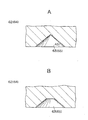
- FIG. 8 is a diagram showing a hemispherical protrusion formed on the surface of the guide wire.
- the protrusion 144 may be formed in a hemispherical shape when viewed from the side in the protruding direction.
- the shape of the concave portion of the mold of the processing apparatus is a hemispherical shape.
- an air escape is formed at the bottom of the mold.
- FIG. 9 is a view showing another embodiment of the shape of the protrusion
- FIG. 10 is a cross-sectional view of the mold of the processing apparatus
- FIG. 9 is a view showing another embodiment of the shape of the protrusion
- a finer protrusion 148 is formed on the surface of the protrusion 144.
- the recesses 32 of the mold 30 of the processing apparatus are formed in such a shape that the protrusions 144 and the fine protrusions 148 match.
- the resin of the guide wire 20 in order to form the fine protrusions 148, the resin of the guide wire 20 must flow into the fine recesses 322. For this reason, an air escape 34 is formed in the concave portion 32 of the mold 30, particularly in the fine concave portion 322.
- the resin can flow into the fine recess 322, and a projection shape as shown in FIG. 9 is obtained.
- the protrusion 144 can be formed in a truncated cone shape or a truncated pyramid shape.
- a finer protrusion 148 on the upper surface of the protrusion 144.
- the frictional resistance between the outer surface of the guide wire 10 and the inner surface of the catheter 20 can be reduced.
- FIG. 13 is a schematic diagram showing a processing apparatus for forming protrusions on the surface of a long body.
- the processing apparatus has two planar dies 50 arranged so as to sandwich the guide wire 10 (long body).
- One of the two molds 50 is fixed, and the other is slidable along the circumference of the guide wire 10 in the direction indicated by the arrow in the figure (direction perpendicular to the axial direction of the guide wire 10).
- the mold 50 has a plurality of recesses 52 formed on the surface on the guide wire 10 side at predetermined intervals. The recess 52 is formed along the sliding direction of the mold 50 and matches the shape to be transferred to the resin layer 14 of the guide wire 10.
- the mold 50 is heated to 80 to 260 degrees, and the guide wire 10 is sandwiched with a force of 0.1 to 200 gf / mm 2 .
- one mold 50 for example, the upper mold 50 in the figure is slid in the direction of the arrow by a distance corresponding to a half circumference of the guide wire 10.
- the protrusions are transferred to the entire circumference of the guide wire 10 by the upper and lower molds 50.
- the guide wire 10 is moved in the axial direction by a predetermined distance by a feeding device (not shown). By repeating this process, a protrusion can be formed over the entire length of the guide wire 10.
- a mold 50 corresponding to the axial length for forming the guide wire protrusion is prepared, and the mold 50 is slid once on the surface of the guide wire 10. Multiple rows of protrusions can be formed.
- FIG. 14 is a view showing an apparatus for manufacturing a medical long body
- FIGS. 15A to 15B are views showing an example of a cross-sectional shape of a concave portion of a mold
- FIG. 16 is an enlarged view showing the shape of the surface of the medical elongated body.
- the manufacturing apparatus 60 includes a first mold roller 62 and a second mold roller 64.
- the first mold roller 62 is formed in a cylindrical shape, and is rotatable around a first rotation shaft 62a inclined with respect to the axial direction of a wire (hereinafter also referred to as “guide wire 10”).
- a plurality of recesses 63 are formed on the cylindrical side surface of the first mold roller 62. The plurality of recesses 63 are uniformly distributed on the cylindrical side surface of the first mold roller 62.
- the second mold roller 64 is formed in a cylindrical shape, and is rotatable about a second rotation shaft 64a that is inclined in the axial direction of the guide wire 10 and crosses the first shaft 62a.
- a plurality of recesses 65 are formed on the cylindrical side surface of the second mold roller 64.
- the plurality of recesses 65 are uniformly distributed on the cylindrical side surface of the second mold roller 64.
- the second mold roller 64 is provided at a position facing the first mold roller 62 with the guide wire 10 interposed therebetween.
- the first rotating shaft 62a and the second rotating shaft 64a face different directions.
- the first rotation shaft 62a and the second rotation shaft 64a are preferably such that the intersection angles A1 and A2 with the shaft of the guide wire 10 are acute angles. More preferably, the intersection angles A1 and A2 are 10 degrees or less. The intersection angles A1, A2 are preferably equal.
- the recess 63 of the first mold roller 62 and the recess 65 of the second mold roller 64 may have any shape.
- the recesses 63 and 65 have a pyramid shape such as a quadrangular pyramid (pyramid shape), for example.
- the recesses 63 and 65 are formed by cutting a pyramid such as a quadrangular pyramid (pyramid shape) from the first mold roller 62 and the second mold roller 64. It is not limited to a quadrangular pyramid, but may be any pyramid such as a triangular pyramid or a hexagonal pyramid. Alternatively, the recesses 63 and 65 may have a conical shape. At this time, the recesses 63 and 65 have a triangular cross-sectional shape as shown in FIG. 15A.
- the recesses 63 and 65 may be, for example, a truncated pyramid shape or a truncated cone shape. At this time, the recesses 63 and 65 have a trapezoidal cross section as shown in FIG. 15B.
- the recess 63 preferably has an inclination angle A3 of the side surface of the recess with respect to the surface of the first mold roller 62 of 60 degrees or less. The same applies to the recess 65. In the following embodiment, a case where a quadrangular pyramid is adopted as the shape of the recesses 63 and 65 will be described.
- the concave portion 63 of the first mold roller 62 and the concave portion 65 of the second mold roller 64 have the same shape.
- the distribution density of the recesses 63 and 65 of the rollers 62 and 64 is preferably the same.
- the first mold roller 62 and the second mold roller 64 are each heated by a heating device 66 such as a glass torch.
- the heating temperature can be appropriately changed according to the material of the resin layer 14 of the guide wire 10 described later.
- the heating device may have a mode in which a heater is embedded in each of the rollers 62 and 64.
- the wire 10 having the resin layer 14 on the surface is prepared. And the 1st metal mold
- the first mold roller 62 and the second mold roller 64 are moved by the glass torch 66 so as to be equal to or higher than the glass transition point (or softening point in the case of amorphous resin) of the resin layer 14 on the surface of the guide wire 10. Is heated.
- the first mold roller 62 and the second mold roller 64 are rotated around the first rotation shaft 62a and the second rotation shaft 64a in the direction of the arrow shown in FIG. Accordingly, the guide wire 10 is rotated in the direction of the large arrow while being rotated as indicated by the arrow in FIG. At this time, a convex portion corresponding to the shape of the concave portion 63 of the first mold roller 62 is formed on the resin on the surface of the guide wire 10 softened by heat. Similarly, a convex portion is formed on the surface of the guide wire 10 by the concave portion 65 of the second mold roller 64.
- the first mold roller 62 and the second mold roller 64 are sequentially applied to different positions on the surface of the guide wire 10. Touched. Convex portions are continuously formed on the surface of the guide wire 10.
- convex portions are uniformly formed on the surface of the guide wire 10 in a predetermined pattern as shown in FIG.
- the multiple helical rows of protrusions are easier to insert because the area of contact with the lumen of the catheter is reduced when the guidewire 10 is moved axially.
- the first shaft 62 a of the first mold roller 62 and the second rotation shaft 64 a of the second mold roller 64 are crossed via the guide wire 10. Therefore, only by rotating the first mold roller 62 and the second mold roller 64, the guide wire 10 is automatically fed, and convex portions are continuously formed on the surface thereof. If the above method and apparatus are used, the productivity is very good even if a medical elongated body such as a guide wire is relatively long.
- the first rotation shaft 62a and the second rotation shaft 64a have acute angles at the intersection angles A1 and A2 with the shaft of the guide wire 10. Therefore, the guide wire 10 can be appropriately sent.
- the concave portions 63 and 65 of the first mold roller 62 and the second mold roller 64 are formed in a pyramid shape, a cone shape, a truncated pyramid shape, or a truncated cone shape.
- the inclination angle A3 of the side surface of the recess with respect to the surface of the first mold roller 62 is 60 degrees or less, there is no edge on which the resin entering the recesses 63 and 65 is caught. Therefore, when the concave portions 63 and 65 are separated from the guide wire 10, the edge is not caught and the convex portion formed on the surface layer of the resin layer 14 is not damaged, and the peeling strength of the convex portion is increased.
- the shape of the recess 65 can be easily transferred to the resin of the resin layer 14.
- FIG. 17 is a view showing a modification of the first mold roller and the second mold roller
- FIG. 18 is a schematic view showing a finished shape of the molded guide wire 10.
- the mold roller 70 has a groove 71 formed along the circumference of a cylindrical side surface. This is different from the first mold roller 62 and the second mold roller 64 of the first embodiment.
- the replaced mold roller 70 is applied to the manufacturing apparatus 60 of FIG.
- the rotation axes of the two mold rollers 70 are arranged so as to cross each other with the axis of the guide wire 10 interposed therebetween. Therefore, a concave / convex pattern intersecting the surface of the guide wire 10 is formed by the grooves 71 of both mold rollers 70. That is, the groove 71 arranged orthogonal to each rotation axis forms a spiral concavo-convex pattern having an intersection angle of the rotation axes. Specifically, it is a mesh pattern as shown in FIG.
- the uneven pattern formed on the surface of the guide wire 10 can be changed by appropriately changing the surface patterns of the first mold roller and the second mold roller.
- FIG. 19 is a diagram showing an apparatus for manufacturing a medical elongated body.
- the manufacturing apparatus 80 includes a pair of mold rollers 81 and 82 and another pair of mold rollers 83 and 84.
- Each of the mold rollers 81 to 84 is formed in a cylindrical shape, and is rotatable around a rotation axis perpendicular to the axial direction of the guide wire 10.
- the pair of mold rollers 81 and 82 or the mold rollers 83 and 84 have parallel rotation axes.
- the mold rollers 81 and 83 are not parallel in rotation axis.
- the mold rollers 81 and 83 have a rotation axis different by 90 degrees.
- the mold rollers 81 to 84 are formed with a plurality of recesses 85 on the cylindrical side surface.
- the plurality of recesses 85 are uniformly distributed on the circumference on the surfaces of the mold rollers 81 to 84. At least on the circumference of the die rollers 81 to 84 contacting the guide wire 10, the concave portions 85 are uniformly distributed.
- the shape of the recess 85 may be any shape, similar to the recesses 63 and 65 of the second embodiment shown in FIGS. 15A and 15B. However, it is preferable that the concave portions 85 of the mold rollers 81 to 84 have the same shape.
- the distribution density of the concave portions 85 of the mold rollers 81 to 84 is preferably the same.
- the mold rollers 81 to 84 are each heated by a heating device 86 such as a glass torch.
- the heating temperature can be appropriately changed according to the material of the resin layer 14 of the guide wire 10 described later.
- the heating device 86 may have a mode in which a heater is embedded in each of the mold rollers 81 to 84.
- a wire 10 having a resin layer 14 on the surface (hereinafter referred to as a guide wire 10) is prepared.
- the pair of mold rollers 81 and 82 and the other pair of mold rollers 83 and 84 are arranged so as to sandwich the guide wire 10, respectively.
- the mold rollers 81 to 84 are heated by the glass torch 86 so as to be equal to or higher than the glass transition point Tg (or softening point in the case of amorphous resin) of the resin layer 14 on the surface of the guide wire 10.
- the mold rollers 81 to 84 are rotated in the directions of the arrows shown in FIG. Along with this, the guide wire 10 is sent in the axial direction. Then, the convex part corresponding to the shape of the recessed part 85 is formed with respect to the resin of the surface of the guide wire 10 softened by heat. Similarly, convex portions are formed on the surface of the guide wire 10 by the concave portions 85 of the mold rollers 81 to 84.
- the mold rollers 81 to 84 are sequentially brought into contact with different positions on the surface of the guide wire 10. Convex portions are continuously formed on the surface of the guide wire 10.
- the guide wire 10 is passed between the mold rollers 81 to 84, so that the convex portions corresponding to the concave portions 85 formed on the surfaces of the mold rollers 81 to 84 are obtained.
- 144 is formed on the surface of the guide wire 10. Therefore, if the above-described method and apparatus are used, the productivity is very good even when a medical long body such as a guide wire is relatively long.
- the guide wire 10 can be uniformly pressed from the entire circumference. Therefore, the guide wire 10 does not rotate during processing, and a uniform uneven surface pattern can be formed.
- the mold rollers 81 to 84 each form a straight concavo-convex surface pattern on the surface of the guide wire 10. According to the pair of mold rollers 81 and 82 whose rotational axes are shifted by 90 degrees and the other pair of mold rollers 83 and 84, four uneven surface patterns are formed on the surface of the guide wire 10 at intervals of 90 degrees. Is done. In order to form a concavo-convex surface pattern on the entire circumference of the guide wire 10, the pattern is transferred to the entire circumference by rotating the guide wire 10 by, for example, 6 degrees and passing it again between the mold rollers 81 to 84. .
- the concave portions 85 of the mold rollers 81 to 84 are formed in a pyramid shape, a cone shape, a truncated pyramid shape, or a truncated cone shape.
- the inclination angle A of the side surface of the recess with respect to the surfaces of the respective mold rollers 81 to 84 is 60 degrees or less, there is no edge on which the resin entering the recess 85 is caught. Therefore, when the concave portion 85 moves away from the guide wire 10, the edge is caught and the convex portion formed on the resin layer 14 on the surface of the guide wire 10 is not damaged, and the peeling strength of the convex portion is increased.
- the shape of the recess 85 can be easily transferred to the resin of the resin layer 14.
- a pair of mold rollers 81 and 82 and another pair of mold rollers 83 and 84 are used.
- the present invention is not limited to this.
- only one pair of mold rollers may be used.
- three or more pairs of mold rollers may be used.
- the positions of the respective mold roller pairs are adjusted so that the uneven surface pattern is formed in a non-overlapping portion of the surface of the guide wire 10. That is, the mold roller pairs are arranged by shifting the rotation shafts of the mold roller pairs by an equal angle.
- the mold roller pairs are arranged by shifting the rotation shafts of the mold roller pairs by an equal angle.
- the manufacturing time of the guide wire 10 can be shortened.
- 24 pairs of mold rollers are prepared. If each pair is arranged so that the rotation axis is shifted by 7.5 degrees, 48 uneven surface patterns can be formed around the guide wire 10 at a time.
- FIG. 20 is a schematic view of a catheter to be placed inside a telescopic type
- FIG. 21 is a partial sectional view of the surface of the catheter shown in FIG.
- the catheter 40 shown in FIG. 20 is used in combination with another catheter, and is inserted through a lumen formed in the length direction of the other catheter.
- the catheter 40 has a distal end portion 42 of a flexible tubular body.
- a lumen 422 is formed substantially at the central portion over the entire length of the catheter body so that a guide wire can be inserted.
- the tip portion 42 is formed of a single layer from a resin.
- a protrusion 424 is formed on the surface of the tip portion 42.
- the protrusion 424 is formed by transferring the shape of the mold by the same method as that for the guide wire 10 described above.
- the protrusion 424 can be formed in any shape such as a hemispherical shape, a truncated cone shape, a truncated pyramid shape, or a shape in which finer protrusions are formed on the surface thereof.
- catheter 40 currently formed in the single layer as a base material is illustrated here, it is not limited to this.
- the catheter may be formed in multiple layers.
- FIG. 22 is a partial cross-sectional view of the surface of a catheter formed in multiple layers.
- the lumen 422 is filled with a core material such as a metal wire, a resin rod, a gas such as nitrogen or oxygen, or a volatile liquid.
- the present invention can be applied not only to the guide wire 10 but also to any medical long body such as the wire catheter 40 used for medical purposes. Moreover, it is applicable not only to a medical use but to the member which needs a low sliding resistance uniformly over the whole resin layer.
- FIG. 15B is a diagram illustrating an example of a cross-sectional shape of a concave portion of a mold. It is an enlarged view which shows the shape of the surface of a medical elongate body. It is a figure which shows the modification of a 1st mold roller and a 2nd mold roller. 4 is a schematic diagram showing a finished shape of a molded guide wire 10.
- FIG. 3 is a schematic view of a catheter placed inside a telescopic type. It is a fragmentary sectional view of the surface of the catheter shown in FIG. It is a fragmentary sectional view of the surface of the catheter currently formed in the multilayer.
Abstract
高い耐久性を維持しつつ、表面に均一な分布で突起を有する長尺体を提供する。ガイドワイヤ10は、素線12と、素線12の表面に被覆され、樹脂からなる樹脂層14と、樹脂層14の表面に均一に分布された複数の突起144と、を有する。
Description
本発明は、医療用長尺体、その製造方法およびその製造装置に関する。
ガイドワイヤやカテーテルのような種々の医療用長尺体が、生体の検査、治療等の様々な用途に用いられている。
カテーテルは、たとえば、PTCA(Percutaneous Transluminal Coronary Angioplasty:経皮的冠状動脈血管形成術)のような外科的手術が困難な部位の治療、または人体への低侵襲を目的とした治療や、心臓血管造影などの検査に用いられる。カテーテルは、ガイドワイヤを生体内の目的部位まで誘導するために用いられる。
PTCAに用いられるガイドワイヤは、バルーンカテーテルの先端より突出された状態で、バルーンカテーテルと共に目的部位である冠状動脈の狭窄部付近まで挿入される。狭窄部では、先に細いガイドワイヤだけが通り抜けて狭窄部を広げつつ、バルーンカテーテルを誘導する。また、PTA(Percutaneous Transluminal Angioplasty:経皮的血管形成術)の場合においても、フェモラール、イリアック、リーナル、シャントなどの末梢血管の狭窄・閉塞部位の再開通のために、PTCAと同様に、ガイドワイヤは、バルーンカテーテルを狭窄部まで誘導する。
ガイドワイヤは、カテーテルのルーメン内や内視鏡の内腔内に挿入され、その長手方向に移動したり回転したりして使用されるが、その際に摺動抵抗(摩擦抵抗)が小さいことが操作性の向上のために好ましい。
そこで、金属製ワイヤの表面に、粒子状物質が添加されたフッ素樹脂被覆層を形成したガイドワイヤが提案されている。US Patent Publication No. 2006-0073264 A1の図1および図2参照。このガイドワイヤによれば、粒子状物質によりフッ素樹脂被覆層の表面に複数の突起が形成される。したがって、カテーテルの内面との接触面積が小さくなり、摩擦抵抗も小さくなる。
しかし、US Patent Publication No. 2006-0073264 A1 記載のガイドワイヤでは、その表面における粒子状物質の分布が均一ではないことがある。したがって、ガイドワイヤの摺動抵抗が部分的に異なったり、製品ごとに異なったりしてしまう可能性がある。これでは、微妙な感覚に頼るガイドワイヤの操作が困難になってしまう。
また、カテーテル内面との接触面積を小さくするために、金属製ワイヤを複数本束ねてねじり、表面にフッ素樹脂被覆層を形成したガイドワイヤも提案されている。US Patent No. US6251085 B1の図2参照.
しかし、Patent No. US6251085 B1のガイドワイヤでは、表面のフッ素樹脂被覆層ではなく、基礎となる金属製ワイヤ自体を加工している。したがって、ガイドワイヤとしての耐久性が弱くなってしまう。
しかし、Patent No. US6251085 B1のガイドワイヤでは、表面のフッ素樹脂被覆層ではなく、基礎となる金属製ワイヤ自体を加工している。したがって、ガイドワイヤとしての耐久性が弱くなってしまう。
本発明は、高い耐久性を維持しつつ、表面に均一な分布で突起を有する長尺体の提供を目的とする。
また、本発明は、表面が全体に亘って均一な滑らかさを有する長尺体の提供を目的とする。
本発明の医療用長尺体は、長尺状の基材と、前記基材の少なくとも一部の表面に被覆あるいは一体に形成された樹脂層と、前記樹脂層の表面に均一に分布された複数の突起と、を有する。
また、本発明の医療用長尺体は、長尺状の基材と、前記基材の少なくとも一部の表面に被覆あるいは一体に形成され、表面に複数の突起を備えた樹脂層と、を有し、前記樹脂層の表面の全体に亘ってSMDが0.22~0.48μmである。
医療用長尺体の製造方法は、次のステップを含む。表面が樹脂により形成されている長尺体を用意する。長尺体の軸方向に対して傾斜した第1回転軸を中心に回転可能であり、円筒状の側面に凹部が形成された第1金型ローラと、長尺体の軸方向に傾斜しかつ第1軸とクロスする第2回転軸を中心に回転可能であり、円筒状の側面に凹部が形成された第2金型ローラとを、長尺体を挟むように配置する。第1金型ローラおよび第2金型ローラを回転させ、長尺体を軸方向に送りつつ、第1金型ローラおよび第2金型ローラの凹部に対応する凸状表面パターンを長尺体上に形成する。
また、医療用長尺体の製造方法は、次のステップを含む。表面が樹脂により形成されている長尺体を用意する。長尺体の軸方向に対して垂直な回転軸を中心に回転可能であり、円筒状の側面に凹部が形成された一対の金型ローラを、長尺体を挟むように配置する。一対の金型ローラを回転させて、長尺体を軸方向に送りつつ、金型ローラの凹部に対応する凸状表面パターンを長尺体上に形成する。
本発明のさらに他の目的、特徴、および利点は、以下の説明に例示される好ましい実施の形態を参酌することによって、明らかになるであろう。
図1はカテーテルに挿通されたガイドワイヤを示す概略図、図2A、図2Bはカテーテルの部分断面図である。なお、図2Aはカテーテルを軸方向と平行に切った断面図、図2Bはカテーテルを軸方向に対して垂直に切った断面図である。
図1に示すように、ガイドワイヤ10は、カテーテル20内部に軸方向に形成されたルーメンを通過可能である。作業者は、ガイドワイヤ10の基端を保持し、前後に移動させることによって、ガイドワイヤ10をカテーテル20中で前後に移動させることができる。
カテーテル20は、可撓性を有する管状体で構成されており、図2A、図2Bに示すように、そのほぼ中心部にはカテーテル本体の全長にわたって、ルーメン22が形成されている。カテーテル20は、生体のたとえば血管に挿入され、ガイドワイヤ10によって患部まで誘導される。カテーテルとしては、たとえば、血管造影用カテーテル、マイクロカテーテル、バルーンカテーテル、心臓カテーテル、肺動脈カテーテル、尿道カテーテルなど様々なものがある。一般的ないかなるカテーテルを用いてもよい。ここでは、カテーテルの機能についての詳細な説明は省略する。
図3はガイドワイヤの断面図、図4はガイドワイヤの表面の形状を示す拡大図、図5はガイドワイヤの加工装置を示す概略図、図6は加工装置の型を示す図、図7は型内で変形する樹脂層の様子を示す図である。
ガイドワイヤ10は、たとえば生体の血管に挿入されたカテーテルを目的部位(患部)まで誘導するために、先行して血管内を進行される医療用器具である。ガイドワイヤ10は、カテーテル内部に軸方向に形成されたルーメンに挿通可能である。したがって、カテーテルは、ガイドワイヤ10に沿って血管内を進行できる。
ガイドワイヤ10は、図3に示すように、多層構造からなる。ガイドワイヤ10は、単一材料、たとえば、ニッケルチタンで形成された1本の線形の素線12と、素線(基材)12の表面に被覆され、樹脂からなる樹脂層14とを含む。樹脂層14は、素線12を密着して覆う下地層140と、下地層140を覆いフッ素を含有する樹脂からなるフッ素樹脂層142とを含む。
素線12の材料としては、ニッケルチタンの代わりに、ステンレス鋼、コバルト合金などが挙げられる。樹脂層14の下地層140としては、耐熱性樹脂や熱硬化樹脂であることが好ましく、例えば、ポリスルホン、ポリイミド、エポキシ樹脂、フェノール樹脂が挙げられる。フッ素樹脂層142は、例えばPTFE、PFA、FEPにて構成されている。下地層140の表面層はフッ素樹脂の代わりに、ポリアミド、ポリエチレン、シリコーン、ポリウレタンにて形成することも可能である。図示はしないが、樹脂層14を単層で構成してもよい。樹脂層14はコーティングにて形成してもよいが、PTFE、PFA、FEPなどのフッ素樹脂製の熱収縮チューブを素線12に収縮させてもよい。
ガイドワイヤ10は、少なくとも表面が樹脂により形成されている。
図3では、図示を省略しているが、フッ素樹脂層142の表面には複数の微細な突起144が形成されている。突起144は、図4に示すように、樹脂層14の表面に均一に分布されている。
このような突起144を形成する方法としては、図5に示す加工装置を用いることが考えられる。図5に示す加工装置は、ガイドワイヤ10を挟んで対称に配置される一対の型30を有する。型30は、それぞれ、図6に示すように、凹部32が形成されている。凹部32が形成された面がガイドワイヤ10に押し付けられるように、加工装置は、型30をガイドワイヤ10の両側から接近させる。接近させるときの圧力は、たとえば、ガイドワイヤ10の直径が0.014インチの場合、300~1200gfであり、好ましくは400~600gfである。
型30は、樹脂層14の融点以下に加熱されている。加熱により、ガイドワイヤ10は、表面の樹脂層14が容易に変形され、突起144が形成される。型30を加熱する温度は、たとえば、80度~260度であり、好ましくは180度~220度である。ただし、樹脂層14を構成する成分によってその融点が異なるので、樹脂に合わせて適宜加熱温度を変更可能である。
型30の凹部32は、底に空気を逃がすための通路、いわゆる空気逃げが形成されていない。したがって、樹脂層14(フッ素樹脂層142)の樹脂は、図7に示すように、凹部32を不完全に埋める程度しか流入しない。したがって、突起144は、図示されるように、主に上面が平らではなくさらに微細な凹凸146が形成される。一方、型30の凹部32に空気逃げを形成してもよい。この場合、空気が逃げられるので、樹脂層14の樹脂は、型30の凹部32を完全に埋めるように流入する。これにより、上面が平らな突起144を形成することもできる。
加工装置は、上記プレス作業を、ガイドワイヤ10を回転させながら、ガイドワイヤ10の全周に突起144が形成されるまで、すなわち、ガイドワイヤ10を略180度回転させるまで行う。全周に突起144が形成されると、加工装置は、図示しない送り装置によりガイドワイヤ10を所定量だけ送り、全周に突起144を形成する。所定量とは、たとえば、形成した突起144が型30の次の加工の際に破壊されない距離である。これを繰り返して、ガイドワイヤ10の全長に渡って全周に突起を形成する。
なお、上記説明では、図4に示すように、楕円の突起144がガイドワイヤ10の表面に形成される。ただし、突起144を上面から見た形状は、楕円に限定されない。円、多角形などいかなる形状でもよい。
以上のようにガイドワイヤ10の表面に複数の突起144を、均一に分布して形成する。ここで、突起144の大きさや分布は、SMDが0.26~0.48μmとなるように、好ましくは0.38~0.46μmとなるように決定する。
SMDとは、表面粗さの平均偏差(Mean Deviation of Surface Geometrical Roughness)を表わし、後述する方法にて測定可能である。SMDが0.48μmを超えると、表面の凹凸が粗くなり摩擦係数が大きくなるので使用時の挿入抵抗が高くなりすぎる。一方、SMDが0.26μmより小さくても表面の凹凸が小さくかえって摩擦係数が大きくなるので使用時の挿入抵抗が高くなってしまう。SMDが0.38~0.42μmであるとより好ましい。
所望のSMDを得るための突起144の大きさや分布は、たとえば、コンピュータシミュレーションによって計算できる。また、他の方法として、トライアンドエラーで最適なパラメータを決定してもよい。型30の凹部32の大きさや、型を押圧する間隔、押圧力等を調節してガイドワイヤ10を試作し、出来たガイドワイヤ10の表面のSMDを測定する。SMDが0.38~0.46μmのガイドワイヤ10が得られた場合に、そのときの型30の凹部32の大きさ、型を押圧する間隔、押圧力等のパラメータを記録する。記録したパラメータを次からの加工に用いることによって、突起144の大きさや分布を一義的に決定できる。
上記SMDの測定方法について説明する。
SMDは、“風合い評価の標準化と解析”(川端 季雄(著) 1980 日本繊維機械学会 第二版)に記載された方法に準拠したカトーテック株式会社製の摩擦感テスターKES-SE(商品名)により測定される。
具体的には、横に1mm間隔で並べた3本のガイドワイヤ10の両端をガラスプレパラートに固定する。ガイドワイヤ10の軸方向に対して垂直な方向から、10gfの荷重をかけて径0.5mmのピアノ線製U字型接触子をガイドワイヤ10に接触させる。接触子の送り速度は1mm/秒であり、送り時間は20秒である。ガイドワイヤ10表面の突起144による接触子の上下振動を検出して、振動振幅を移動方向に積分した値がSMDである。下記の式で表される。

T:検出厚み(μm)
T:平均厚み(μm)
x:移動距離(20mm)
(効果)
以上のように、上記第1実施形態によれば、樹脂層14の表面には均一に分布された複数の突起144が形成される。したがって、ガイドワイヤ10は、カテーテル20に挿通したときに、カテーテル20内面と触れる接触面積が小さくなる。ガイドワイヤ10の樹脂層14の全体に亘って均一に低い摺動抵抗が得られる。
T:平均厚み(μm)
x:移動距離(20mm)
(効果)
以上のように、上記第1実施形態によれば、樹脂層14の表面には均一に分布された複数の突起144が形成される。したがって、ガイドワイヤ10は、カテーテル20に挿通したときに、カテーテル20内面と触れる接触面積が小さくなる。ガイドワイヤ10の樹脂層14の全体に亘って均一に低い摺動抵抗が得られる。
また、上記第1実施形態によれば、樹脂層14の表面には均一に分布された複数の突起144が、SMDが0.22~0.48μmとなるように形成される。ガイドワイヤ10の樹脂層14の全体に亘って均一に低い摺動抵抗が得られる。ガイドワイヤ10のSMDが0.22~0.48μmであるので、作業者は、どのガイドワイヤ10を用いてもほぼ同じような感覚で作業できる。
樹脂層14の表面に均一に分布された複数の突起144の表面粗さRzは、レーザ顕微鏡(キーエンス株式会社、VK-8500)において0.2~3μmであることが好ましく、0.8~1.5μmであることがより好ましい。
突起144の密度としては、0.04mm2中に15個以上存在することが好ましく、20~60個がより好ましい。
素線12は、表面に樹脂層14が形成される以外、特殊な加工が施されることなく用いられている。すなわち、素線の物性を変化させるような熱影響がガイドワイヤ10の製造上発生しない。したがって、製品として強い強度が得られる。また、素線12は、ねじり等の外力も加えられないので、この点からも強い強度が得られる。
上記のように、型30の凹部32に空気逃げを形成しない場合、突起144表面にはさらに微細な凹凸146が形成される。したがって、ガイドワイヤ10とカテーテル20との接触面積をより小さくでき、より低い摺動抵抗が得られる。
樹脂層14は、下地層140と、フッ素樹脂層142との2層構造よりなる。したがって、最外層にコーティングに優れたフッ素樹脂層142を用いることができる。
(ガイドワイヤの変形例)
以下、ガイドワイヤの変形例について、説明する。
以下、ガイドワイヤの変形例について、説明する。
(ガイドワイヤの変形例1)
以上、上記第1実施形態では、図7に示すように、突起144が突出方向横側から見て、四角形状であった。しかし、これに限定されない。
以上、上記第1実施形態では、図7に示すように、突起144が突出方向横側から見て、四角形状であった。しかし、これに限定されない。
図8は、ガイドワイヤ表面に形成された半球形状の突起を示す図である。
図8に示すように、突起144は、突出方向の横側から見て半球形状に形成されてもよい。この場合、加工装置の型の凹部の形状を半球形状とする。ここで、型の底には、空気逃げを形成する。これにより、型の形状に合致する突起144の形状が得られる。
(ガイドワイヤの変形例2)
図9は突起の形状の他の態様を示す図、図10は加工装置の型の断面図、図11は突起がカテーテル内面に接触する様子を示す図である。
図9は突起の形状の他の態様を示す図、図10は加工装置の型の断面図、図11は突起がカテーテル内面に接触する様子を示す図である。
変形例2では、突起144の表面にさらに微細な突起148が形成されている。このように微細な突起148を形成するには、図10に示すように加工装置の型30の凹部32を、突起144および微細な突起148が合致するような形状に形成する。ここで、微細な突起148を形成するためには、微細な凹部322にガイドワイヤ20の樹脂が流入しなくてはならない。このため、型30の凹部32、特に微細な凹部322には、空気逃げ34が形成されている。これにより、型30がガイドワイヤ20に押圧されたときに、樹脂が微細な凹部322にも流入でき、図9に示すような突起形状が得られる。
このように突起144にさらに微細な突起148を形成した場合、図11に示すように、突起144の表面の曲率がカテーテル20の内面の曲率と等しい場合でも、微細突起148しか、カテーテル20内面に接触しない。したがって、ガイドワイヤ10とカテーテル20との接触面積が小さく、摩擦抵抗が小さくなる。
(ガイドワイヤの変形例3)
図12は、突起の形状の他の態様を示す図である。
図12は、突起の形状の他の態様を示す図である。
図12に示すように、突起144を円錐台や角錐台形状にすることもできる。
この場合、突起144の上面に更に微細な突起148を形成することが好ましい。微細な突起148を形成することによって、ガイドワイヤ10外面とカテーテル20内面の摩擦抵抗を小さくできる。
次に、ガイドワイヤの変形例について、説明する。
(製造方法の変形例)
上記実施形態では、型30を長尺体の軸の垂直方向に押圧することによって、スタンプのように長尺体の表面に突起を転写する方法を説明している。これを改良して、次のような方法で、長尺体の表面に突起を形成することもできる。
上記実施形態では、型30を長尺体の軸の垂直方向に押圧することによって、スタンプのように長尺体の表面に突起を転写する方法を説明している。これを改良して、次のような方法で、長尺体の表面に突起を形成することもできる。
図13は、長尺体の表面に突起を形成する加工装置を示す概略図である。
加工装置は、ガイドワイヤ10(長尺体)を挟むように配置される2つの平面状型50を有する。2つの型50のうちの一方は固定されており、他方はガイドワイヤ10の円周に沿って図中矢印で示す方向(ガイドワイヤ10の軸方向に対して垂直な方向)にスライド可能である。型50は、ガイドワイヤ10側の表面に複数の凹部52が所定間隔を置いて複数列形成されている。凹部52は、型50のスライド方向に沿って形成されており、ガイドワイヤ10の樹脂層14に転写したい形状に合致する。
加工の際には、まず、型50を80~260度に加熱し、0.1~200gf/mm2の力でガイドワイヤ10を挟みこむ。そして、一方の型50、たとえば、図中上側の型50を矢印の方向にガイドワイヤ10の半周分の距離だけスライドさせる。すると、上下の型50により、ガイドワイヤ10の全周に突起が転写される。続けて、図示しない送り装置により、ガイドワイヤ10を軸方向に所定距離移動させる。この処理を繰り返すことによって、ガイドワイヤ10の全長にわたって突起を形成できる。
なお、転写処理を複数回繰り返す工程を上述したが、ガイドワイヤの突起を形成する軸方向の長さ分の型50を準備して、型50の一回のスライドにより、ガイドワイヤ10の表面に複数列の突起を形成できる。
(第2実施形態)
第2実施形態では、上記第1実施形態のガイドワイヤの製造装置および製造方法を改良した形態を示す。
第2実施形態では、上記第1実施形態のガイドワイヤの製造装置および製造方法を改良した形態を示す。
図14は、医療用長尺体の製造装置を示す図、図15A~図15Bは、金型の凹部の断面形状の例を示す図である。図16は、医療用長尺体の表面の形状を示す拡大図である。
本実施形態では、医療用長尺体として、ガイドワイヤ10を製造するための製造方法および製造装置について説明する。
(装置構成)
図14に示すように、製造装置60は、第1金型ローラ62と第2金型ローラ64とを有する。第1金型ローラ62は、円筒状に形成されており、ワイヤ(以下、「ガイドワイヤ10」とも呼ぶ)の軸方向に対して傾斜した第1回転軸62aを中心に回転可能である。第1金型ローラ62の円筒状の側面には、複数の凹部63が形成されている。複数の凹部63は、第1金型ローラ62の円筒の側面に均一に分布されている。
図14に示すように、製造装置60は、第1金型ローラ62と第2金型ローラ64とを有する。第1金型ローラ62は、円筒状に形成されており、ワイヤ(以下、「ガイドワイヤ10」とも呼ぶ)の軸方向に対して傾斜した第1回転軸62aを中心に回転可能である。第1金型ローラ62の円筒状の側面には、複数の凹部63が形成されている。複数の凹部63は、第1金型ローラ62の円筒の側面に均一に分布されている。
第2金型ローラ64は、円筒状に形成されており、ガイドワイヤ10の軸方向に傾斜しかつ第1軸62aとクロスする第2回転軸64aを中心に回転可能である。第2金型ローラ64の円筒状の側面には、複数の凹部65が形成されている。複数の凹部65は、第2金型ローラ64の円筒の側面に均一に分布されている。第2金型ローラ64はガイドワイヤ10を挟んで第1金型ローラ62と対向する位置に設けられている。第1回転軸62aと第2回転軸64aは異なる方向を向いている。
第1回転軸62aおよび第2回転軸64aは、好ましくは、ガイドワイヤ10の軸との交角A1、A2が鋭角である。より好ましくは、交角A1、A2は、10度以下である。交角A1、A2は、好ましくは等しい。
第1金型ローラ62の凹部63および第2金型ローラ64の凹部65は、いかなる形状であってもよい。
凹部63、65は、たとえば、四角錐(ピラミッド形状)などの角錐状である。凹部63、65は、第1金型ローラ62、第2金型ローラ64から四角錐(ピラミッド形状)などの角錐を切り取って形成される。四角錐に限らず、三角錐や、六角錐など、いかなる角錐であってもよい。あるいは、凹部63、65は、円錐形状でもよい。このとき、凹部63、65は、図15Aに示すように、断面形状が三角形になる。
また、凹部63、65は、たとえば、角錐台状や円錐台状であってもよい。このとき、凹部63、65は、図15Bに示すように、断面形状が台形となる。凹部63、65が角錐、円錐、角錐台、円錐台状となる場合、凹部63は、第1金型ローラ62の表面に対する凹部の側面の傾斜角A3が60度以下であることが好ましい。凹部65も同様である。以下の実施形態では、凹部63、65の形状に、四角錐を採用した場合を説明する。
第1金型ローラ62の凹部63と第2金型ローラ64の凹部65はその形状が同じであることが好ましい。各ローラ62、64の凹部63、65の分布密度は同じであるのが好ましい。
第1金型ローラ62および第2金型ローラ64は、それぞれ、ガラストーチなどの加熱装置66によって加熱される。後述するガイドワイヤ10の樹脂層14の材料に従って、加熱温度は適宜変更可能である。加熱装置は、各ローラ62、64の内部にヒータを埋め込んだ態様であってもよい。
(製造手順)
まず、表面に樹脂層14を有するワイヤ10が用意される。そして、第1金型ローラ62および第2金型ローラ64が、ガイドワイヤ10を挟むように配置される。
まず、表面に樹脂層14を有するワイヤ10が用意される。そして、第1金型ローラ62および第2金型ローラ64が、ガイドワイヤ10を挟むように配置される。
ガイドワイヤ10表面の樹脂層14のガラス転移点(もしくは、非晶性樹脂の場合は、軟化点)以上となるように、ガラストーチ66により、第1金型ローラ62および第2金型ローラ64が加熱される。
第1金型ローラ62および第2金型ローラ64が図14に示す矢印の方向に第1回転軸62aおよび第2回転軸64aを中心に回転される。これに伴い、図1に矢印で示すようにガイドワイヤ10が回転されつつ、大きな矢印の方向に送られる。このとき、熱で柔らかくなったガイドワイヤ10の表面の樹脂に対し、第1金型ローラ62の凹部63の形状に対応する凸部が形成される。同様に、第2金型ローラ64の凹部65により、ガイドワイヤ10表面に凸部が形成される。
第1金型ローラ62および第2金型ローラ64の回転に従ってガイドワイヤ10が送られるので、ガイドワイヤ10の表面の異なる位置に、第1金型ローラ62および第2金型ローラ64が順次当接される。ガイドワイヤ10の表面に連続して凸部が形成されていく。
このようにして、ガイドワイヤ10の表面には、図16に示すように、表面に均一に所定のパターンで、凸部が形成される。多数の螺旋状列の凸部は、ガイドワイヤ10をその軸方向に移動させるとき、カテーテルのルーメンとの接触面積が少なくなるので、挿入がより容易になる。
(効果)
以上のように、第2実施形態によれば、第1金型ローラ62の第1軸62aと、第2金型ローラ64の第2回転軸64aがガイドワイヤ10を介してクロスしている。したがって、第1金型ローラ62および第2金型ローラ64を回転させるだけで、ガイドワイヤ10が自動的に送られつつ、その表面に凸部が連続的に形成される。上記方法および装置を用いれば、ガイドワイヤなどの医療用長尺体が比較的長くても、生産性が非常によい。
以上のように、第2実施形態によれば、第1金型ローラ62の第1軸62aと、第2金型ローラ64の第2回転軸64aがガイドワイヤ10を介してクロスしている。したがって、第1金型ローラ62および第2金型ローラ64を回転させるだけで、ガイドワイヤ10が自動的に送られつつ、その表面に凸部が連続的に形成される。上記方法および装置を用いれば、ガイドワイヤなどの医療用長尺体が比較的長くても、生産性が非常によい。
第1回転軸62aおよび第2回転軸64aは、ガイドワイヤ10の軸との交角A1、A2が鋭角である。したがって、ガイドワイヤ10を適切に送ることができる。
第1金型ローラ62および第2金型ローラ64の凹部63、65を、角錐、円錐、角錐台または円錐台状に形成している。特に、第1金型ローラ62の表面に対する凹部の側面の傾斜角A3が60度以下であれば、凹部63、65に入り込んだ樹脂が引っ掛かるエッジがない。したがって、凹部63、65がガイドワイヤ10から離れる際に、エッジが引っ掛かって樹脂層14の表面層の形成された凸部が破損されることがなく、該凸部のはがれ強度が高められる。
第1金型ローラ62および第2金型ローラ64を加熱しているので、樹脂層14の樹脂に凹部65の形状を容易に転写できる。
(第2実施形態の変形例)
上記第2実施形態では、第1金型ローラ62および第2金型ローラ64に、凹部63、65が形成されている例を説明した。しかし、これに限定されない。以下に示すように、第1金型ローラおよび第2金型ローラを変形できる。
上記第2実施形態では、第1金型ローラ62および第2金型ローラ64に、凹部63、65が形成されている例を説明した。しかし、これに限定されない。以下に示すように、第1金型ローラおよび第2金型ローラを変形できる。
図17は第1金型ローラおよび第2金型ローラの変形例を示す図、図18は成形されたガイドワイヤ10の出来上がり形状を示す該略図である。
図17に示す金型ローラ70を、図14の第1金型ローラ62および第2金型ローラ64に代えて使用できる。金型ローラ70は、円筒状の側面の円周に沿って溝71が形成されている。この点で、第1実施形態の第1金型ローラ62および第2金型ローラ64とは異なる。
このように、置き換えた金型ローラ70を、図14の製造装置60に適用する。金型ローラ70を第1金型ローラおよび第2金型ローラとして回転させることによって、2つの金型ローラ70の各回転軸がガイドワイヤ10の軸を挟んでクロスするように配置される。したがって、双方の金型ローラ70の溝71によって、ガイドワイヤ10表面に交差する凹凸パターンが形成される。すなわち、各回転軸と直交して配置される溝71により、回転軸の交角を有する螺旋状凹凸パターンとなる。具体的には、図18に示すような網目状パターンである。
以上のように、第1金型ローラおよび第2金型ローラの表面パターンを適宜変更することによって、ガイドワイヤ10の表面に形成する凹凸パターンも変更できる。
(第3実施形態)
第3実施形態では、上記第1実施形態および第2実施形態のガイドワイヤの製造装置および製造方法をさらに改良した形態を示す。
第3実施形態では、上記第1実施形態および第2実施形態のガイドワイヤの製造装置および製造方法をさらに改良した形態を示す。
図19は、医療用長尺体の製造装置を示す図である。
本実施形態では、医療用長尺体として、ガイドワイヤ10を製造するための製造方法および製造装置について説明する。
(装置構成)
図19に示すように、製造装置80は、一対の金型ローラ81、82と、他の一対の金型ローラ83、84とを有する。各金型ローラ81~84は、円筒状に形成されており、ガイドワイヤ10の軸方向に対して垂直な回転軸を中心に回転可能である。対をなす金型ローラ81および82、あるいは金型ローラ83および84は、回転軸が平行である。一方、金型ローラ81および83は、回転軸が平行ではない。本実施形態では、金型ローラ81と83とは、回転軸が90度異なる。
図19に示すように、製造装置80は、一対の金型ローラ81、82と、他の一対の金型ローラ83、84とを有する。各金型ローラ81~84は、円筒状に形成されており、ガイドワイヤ10の軸方向に対して垂直な回転軸を中心に回転可能である。対をなす金型ローラ81および82、あるいは金型ローラ83および84は、回転軸が平行である。一方、金型ローラ81および83は、回転軸が平行ではない。本実施形態では、金型ローラ81と83とは、回転軸が90度異なる。
金型ローラ81~84には、円筒状の側面に複数の凹部85が形成されている。複数の凹部85は、金型ローラ81~84の表面において、円周上に均一に分布されている。少なくとも、金型ローラ81~84のガイドワイヤ10と接触する円周上には、均一に凹部85が分布されている。凹部85の形状は、図15A、15Bに示す第2実施形態の凹部63、65と同様に、いかなる形状であってもよい。ただし、金型ローラ81~84の凹部85はその形状が同じであることが好ましい。金型ローラ81~84の凹部85の分布密度は同じであることが好ましい。
以下の実施形態では、凹部85の形状に、四角錐を採用した場合を説明する。
金型ローラ81~84は、それぞれ、ガラストーチなどの加熱装置86によって加熱される。後述するガイドワイヤ10の樹脂層14の材料に従って、加熱温度は適宜変更可能である。加熱装置86は、各金型ローラ81~84の内部にヒータを埋め込んだ態様であってもよい。
(製造手順)
まず、表面に樹脂層14を有するワイヤ10(以下、ガイドワイヤ10という)が用意される。
まず、表面に樹脂層14を有するワイヤ10(以下、ガイドワイヤ10という)が用意される。
そして、一対の金型ローラ81、82および他の一対の金型ローラ83、84が、それぞれ、ガイドワイヤ10を挟むように配置される。
ガイドワイヤ10表面の樹脂層14のガラス転移点Tg(もしくは、非晶性樹脂の場合は軟化点)以上となるように、ガラストーチ86により、金型ローラ81~84が加熱される。
金型ローラ81~84は、図19に示す矢印の方向にそれぞれ回転される。これに伴い、ガイドワイヤ10が軸方向に送られる。すると、熱で柔らかくなったガイドワイヤ10の表面の樹脂に対し、凹部85の形状に対応する凸部が形成される。同様に、金型ローラ81~84の凹部85により、ガイドワイヤ10表面に凸部が形成される。
金型ローラ81~84の回転に従ってガイドワイヤ10が送られるので、ガイドワイヤ10の表面の異なる位置に、金型ローラ81~84が順次当接される。ガイドワイヤ10の表面に連続して凸部が形成されていく。
(効果)
以上のように、上記第3実施形態によれば、金型ローラ81~84の間にガイドワイヤ10を通すことによって、各金型ローラ81~84表面に形成された凹部85に対応する凸部144がガイドワイヤ10表面に形成される。したがって、上記方法および装置を用いれば、ガイドワイヤなどの医療用長尺体が比較的長くても、生産性が非常によい。
以上のように、上記第3実施形態によれば、金型ローラ81~84の間にガイドワイヤ10を通すことによって、各金型ローラ81~84表面に形成された凹部85に対応する凸部144がガイドワイヤ10表面に形成される。したがって、上記方法および装置を用いれば、ガイドワイヤなどの医療用長尺体が比較的長くても、生産性が非常によい。
加えて、上記のように、回転軸が90度異なる2対の金型ローラ81、82および83、84を有するので、ガイドワイヤ10を全周から均一に押さえられる。したがって、加工中にガイドワイヤ10が回転せず、均一な凹凸状表面パターンを形成できる。
金型ローラ81~84は、それぞれ、ガイドワイヤ10表面に一直線の凹凸状表面パターンを形成する。回転軸が90度ずれた一対の金型ローラ81、82と、他の一対の金型ローラ83、84とによれば、90度間隔に4本の凹凸状表面パターンがガイドワイヤ10表面に形成される。ガイドワイヤ10の全周に凹凸状表面パターンを形成するためには、ガイドワイヤ10をたとえば、6度だけ回転させて、再び、金型ローラ81~84間に通すことで全周にパターン転写する。
金型ローラ81~84の凹部85を、角錐、円錐、角錐台または円錐台状に形成している。特に、各金型ローラ81~84の表面に対する凹部の側面の傾斜角Aが60度以下であれば、凹部85に入り込んだ樹脂が引っ掛かるエッジがない。したがって、凹部85がガイドワイヤ10から離れる際に、エッジが引っ掛かってガイドワイヤ10表面の樹脂層14に形成された凸部が破損されることがなく、該凸部のはがれ強度が高められる。
金型ローラ81~84を加熱しているので、樹脂層14の樹脂に凹部85の形状を容易に転写できる。
(金型ローラの変更例)
上記第3実施形態では、対の金型ローラ81、82および他の対の金型ローラ83、84を用いていた。しかし、本発明はこれに限定されない。たとえば、金型ローラは1対だけ用いられてもよい。
上記第3実施形態では、対の金型ローラ81、82および他の対の金型ローラ83、84を用いていた。しかし、本発明はこれに限定されない。たとえば、金型ローラは1対だけ用いられてもよい。
あるいは、金型ローラは3対以上用いられてもよい。この場合、ガイドワイヤ10の表面の重複しない箇所に凹凸状表面パターンが形成されるように、各金型ローラ対の位置を調整する。すなわち、各金型ローラ対の回転軸を均等な角度でずらして、各金型ローラ対を配置する。これにより、ガイドワイヤ10を複数対の金型ローラ間に通すだけで、金型ローラの数だけ直線状の凹凸状表面パターンを一度に形成できる。これにより、ガイドワイヤ10の製造時間を短縮できる。たとえば、金型ローラは、24対用意される。各対を回転軸が7.5度ずつずれるように配置すれば、48本の凹凸状表面パターンをガイドワイヤ10の周に一度に形成できる。
(カテーテル)
上記実施形態1~3では、ガイドワイヤ10の表面に突起を形成する例を説明してきた。しかし、本発明はこれに限定されない。入れ子式に用いられるカテーテルの場合、内側に配置されるカテーテルの表面に、上記ガイドワイヤ10のように均一に分布された突起を形成できる。
上記実施形態1~3では、ガイドワイヤ10の表面に突起を形成する例を説明してきた。しかし、本発明はこれに限定されない。入れ子式に用いられるカテーテルの場合、内側に配置されるカテーテルの表面に、上記ガイドワイヤ10のように均一に分布された突起を形成できる。
図20は入れ子式の内側に入れられるカテーテルの概略図、図21は図20に示すカテーテルの表面の部分断面図である。
図20に示すカテーテル40は、他のカテーテルを組み合わせて使用されるものであり、他のカテーテルの長さ方向に形成されたルーメンに挿通される。カテーテル40は、可撓性を有する管状体の先端部42を有する。先端部42は、ガイドワイヤが挿通可能なようにルーメン422がほぼ中心部にカテーテル本体の全長にわたって形成されている。先端部42は、単層で樹脂から形成されている。
先端部42の表面には、図21に示すように、突起424が形成される。突起424は、前述のガイドワイヤ10と同様の手法により、型の形状を転写することによって形成される。突起424は、上述のように、半球形状、円錐台形状、角錐台形状、それらの表面にさらに微細な突起が形成された形状など、いかなる形状にも形成できる。
なお、ここでは、基材として単層に形成されているカテーテル40を例示しているが、これに限定されない。カテーテルを多層に形成してもよい。
図22は、多層に形成されているカテーテルの表面の部分断面図である。
図22に示すカテーテルの先端部42は、基材44の表面に下地層46が設けられ、さらに下地層46の表面にフッ素樹脂層48が設けられている。基材44には、ガイドワイヤが挿通可能なルーメン422が形成されている。下地層46およびフッ素樹脂層48は、たとえば、樹脂で形成されており、あるいは、可撓性を有する他の材料で形成されている。突起424は、フッ素樹脂層48の表面に形成される。
突起424がカテーテル40の表面に形成される場合は、金属線、樹脂棒、窒素や酸素などの気体、揮発性の液体などの芯材料がルーメン422に充填するのが好ましい。
このように、本発明は、ガイドワイヤ10だけでなく、医療用途に用いるワイヤカテーテル40などのいかなる医療用長尺体にも適用できる。また、医療用途に限らず、樹脂層全体に亘って均一に低い摺動抵抗が必要な部材に適用できる。
なお、本出願は、2007年12月26日に出願された米国仮出願第61/016,749号、2007年12月27日に出願された日本国特許出願第2007-338104号、2008年1月25日に出願された米国仮出願第61/006,678号、2008年1月25日に出願された日本国特許出願2008-015153号、2008年2月19日に出願された米国仮出願第61/064,137号、2008年2月28日に出願された米国仮出願第61/064,332号に基づいており、その開示内容は、参照により全体として引用されている。
Claims (35)
- 長尺状の基材と、
前記基材の少なくとも一部の表面に被覆あるいは一体に形成された樹脂層と、
前記樹脂層の表面に均一に分布された複数の突起と、
を有する医療用長尺体。 - 前記突起は、表面にさらに微細な凹凸が形成されている請求項1記載の医療用長尺体。
- 前記突起は、前記樹脂層の表面に加熱された型が押圧されることによって、前記樹脂層の表面が変形されて形成される請求項1または請求項2に記載の医療用長尺体。
- 前記樹脂層の表面のSMDは、0.26~0.48μmである請求項1~3のいずれか一項に記載の医療用長尺体。
- 前記樹脂層は、
前記基材とは別体に設けられており、
前記基材を密着して覆う下地層と、
前記下地層を覆いフッ素を含有する樹脂からなるフッ素樹脂層と
を含む請求項1~4のいずれか一項に記載の医療用長尺体。 - 長尺状の基材と、
前記基材の少なくとも一部の表面に被覆あるいは一体に形成され、表面に複数の突起を備えた樹脂層と、
を有し、
前記樹脂層の表面の全体に亘ってSMDが0.22~0.48μmである医療用長尺体。 - 前記突起は前記樹脂層の表面に均一に分布されて、該突起によりSMDが決定される請求項6記載の医療用長尺体。
- 前記突起は、表面にさらに微細な凹凸が形成されている請求項6記載の医療用長尺体。
- 前記樹脂層は、
前記基材とは別体に設けられており、
前記基材を密着して覆う下地層と、
前記下地層を覆いフッ素を含有する樹脂からなるフッ素樹脂層と
を含む請求項6~8のいずれか一項に記載の医療用長尺体。 - 表面が樹脂により形成されている長尺体を用意し、
前記長尺体の軸方向に対して傾斜した第1回転軸を中心に回転可能であり、円筒状の側面に凹部が形成された第1金型ローラと、前記長尺体の軸方向に傾斜しかつ前記第1軸とクロスする第2回転軸を中心に回転可能であり、円筒状の側面に凹部が形成された第2金型ローラとを、前記長尺体を挟むように配置し、
前記第1金型ローラおよび前記第2金型ローラを回転させ、前記長尺体を軸方向に送りつつ、前記第1金型ローラおよび第2金型ローラの凹部に対応する凹凸状表面パターンを前記長尺体上に形成する医療用長尺体の製造方法。 - 前記第1回転軸および前記第2回転軸は、前記長尺体の軸との交角が鋭角である請求項10記載の医療用長尺体の製造方法。
- 前記第1回転軸および前記第2回転軸は、前記長尺体の軸との交角が共に等しい請求項10または請求項11に記載の医療用長尺体の製造方法。
- 前記第1金型ローラおよび前記第2金型ローラの表面の前記凹部の形状は、角錐状または角錐台状であり、
前記第1金型ローラおよび前記第2金型ローラを回転させる際には、前記長尺体の表面に均等に配置されたドットパターンを形成する請求項10~12のいずれか一項に記載の医療用長尺体の製造方法。 - 前記第1金型ローラおよび前記第2金型ローラの表面の前記凹部は、前記第1金型ローラおよび前記第2金型ローラの表面に対する前記凹部の側面の傾斜角が60度以下である請求項10~13のいずれか一項に記載の医療用長尺体の製造方法。
- 前記第1金型ローラおよび前記第2金型ローラの凹部は、円筒状の側面の円周に沿って形成された溝であり、
前記第1金型ローラおよび前記第2金型ローラを回転させる際には、前記長尺体の表面に網目状のパターンを形成する請求項10~12のいずれか一項に記載の医療用長尺体の製造方法。 - 前記第1金型ローラおよび前記第2金型ローラは、加熱装置により加熱されている請求項10~15のいずれか一項に記載の医療用長尺体の製造方法。
- 表面が樹脂により形成されている長尺体の軸方向に対して傾斜した第1回転軸を中心に回転可能であり、円筒状の側面に凹部が形成された第1金型ローラと、
前記長尺体の軸方向に傾斜しかつ前記第1軸とクロスする第2回転軸を中心に回転可能であり、円筒状の側面に凹部が形成され、前記第1金型ローラと共に前記長尺体を挟む第2金型ローラと、
を有し、
前記第1金型ローラおよび前記第2金型ローラが回転することによって、前記長尺体を軸方向に送りつつ、前記第1金型ローラおよび第2金型ローラの凹部に対応する凹凸状表面パターンを形成する医療用長尺体の製造装置。 - 前記第1回転軸および前記第2回転軸は、前記長尺体の軸との交角が鋭角である請求項17記載の医療用長尺体の製造装置。
- 前記第1回転軸および前記第2回転軸は、前記長尺体の軸との交角が共に等しい請求項17または請求項18記載の医療用長尺体の製造装置。
- 前記第1金型ローラおよび前記第2金型ローラの表面の前記凹部の形状は、半球状、角錐状または角錐台状であり、
前記第1金型ローラおよび前記第2金型ローラを回転させる際には、前記長尺体の表面に均等に配置されたドットパターンを形成する請求項17~19のいずれか一項に記載の医療用長尺体の製造装置。 - 前記第1金型ローラおよび前記第2金型ローラの表面の前記凹部は、前記第1金型ローラおよび前記第2金型ローラの表面に対する前記凹部の側面の傾斜角が60度以下である請求項17~20のいずれか一項に記載の医療用長尺体の製造装置。
- 前記第1金型ローラおよび前記第2金型ローラの凹部は、円筒状の側面の円周に沿って形成された溝であり、
前記第1金型ローラおよび前記第2金型ローラを回転させる際には、前記長尺体の表面に網目状のパターンを形成する請求項17~19のいずれか一項に記載の医療用長尺体の製造装置。 - 前記第1金型ローラおよび前記第2金型ローラは、加熱装置により加熱されている請求項17~22のいずれか一項に記載の医療用長尺体の製造装置。
- 表面が樹脂により形成されている長尺体を用意し、
前記長尺体の軸方向に対して垂直な回転軸を中心に回転可能であり、円筒状の側面に凹部が形成された一対の金型ローラを、前記長尺体を挟むように配置し、
前記一対の金型ローラを回転させて、前記長尺体を軸方向に送りつつ、前記金型ローラの凹部に対応する凹凸状表面パターンを前記長尺体上に形成する医療用長尺体の製造方法。 - 前記一対の金型ローラは、複数対用意され、それぞれの対の回転軸は異なる方向を向いており、
前記長尺体は、前記複数対の金型ローラ間を通されて、重複しない箇所に前記凹凸状表面パターンが形成される請求項24記載の医療用長尺体の製造方法。 - 前記一対の金型ローラは、2対用意され、一方の対の回転軸は、他方の対の回転軸に対して垂直である請求項24記載の医療用長尺体の製造方法。
- 前記金型ローラの表面の凹部の形状は、角錐状または角錐台状である請求項24~26のいずれか一項に1記載の医療用長尺体の製造方法。
- 前記金型ローラの表面の前記凹部は、前記金型ローラの表面に対する前記凹部の側面の傾斜角が60度以下である請求項24~27のいずれか一項に記載の医療用長尺体の製造方法。
- 前記金型ローラは、加熱装置により加熱されている請求項24~28のいずれか一項に記載の医療用長尺体の製造方法。
- 表面が樹脂により形成されている長尺体の軸方向に対して垂直な回転軸を中心に回転可能であり、円筒状の側面に凹部が形成された一対の金型ローラと、
を有し、
前記一対の金型ローラ間に前記長尺体を挟み、前記一対の金型ローラを回転させて、前記金型ローラの凹部に対応する凹凸状表面パターンを前記長尺体上に形成する医療用長尺体の製造装置。 - 前記一対の金型ローラは、複数対用意され、それぞれの対の回転軸は異なる方向を向いており、
前記長尺体は、前記複数対の金型ローラ間を通されて、重複しない箇所に前記凹凸状表面パターンが形成される請求項30記載の医療用長尺体の製造装置。 - 前記一対の金型ローラは、2対用意され、一方の対の回転軸は、他方の対の回転軸に対して垂直である請求項30記載の医療用長尺体の製造装置。
- 前記金型ローラの表面の凹部の形状は、角錐状または角錐台状である請求項30~32のいずれか一項に記載の医療用長尺体の製造装置。
- 前記金型ローラの表面の前記凹部は、前記金型ローラの表面に対する前記凹部の側面の傾斜角が60度以下である請求項30~33のいずれか一項に記載の医療用長尺体の製造方法。
- 前記金型ローラは、加熱装置により加熱されている請求項30~34のいずれか一項に記載の医療用長尺体の製造装置。
Priority Applications (2)
| Application Number | Priority Date | Filing Date | Title |
|---|---|---|---|
| JP2009547069A JP5619426B2 (ja) | 2007-12-26 | 2008-12-18 | 医療用長尺体、その製造方法およびその製造装置 |
| EP08864849.8A EP2226091B1 (en) | 2007-12-26 | 2008-12-18 | Medical long element, method for manufacturing the same, and apparatus for manufacturing the same |
Applications Claiming Priority (12)
| Application Number | Priority Date | Filing Date | Title |
|---|---|---|---|
| US1674907P | 2007-12-26 | 2007-12-26 | |
| US61/016,749 | 2007-12-26 | ||
| JP2007-338104 | 2007-12-27 | ||
| JP2007338104 | 2007-12-27 | ||
| US667808P | 2008-01-25 | 2008-01-25 | |
| JP2008015153 | 2008-01-25 | ||
| US61/006,678 | 2008-01-25 | ||
| JP2008-015153 | 2008-01-25 | ||
| US6413708P | 2008-02-19 | 2008-02-19 | |
| US61/064,137 | 2008-02-19 | ||
| US6433208P | 2008-02-28 | 2008-02-28 | |
| US61/064,332 | 2008-02-28 |
Publications (1)
| Publication Number | Publication Date |
|---|---|
| WO2009081844A1 true WO2009081844A1 (ja) | 2009-07-02 |
Family
ID=40799396
Family Applications (1)
| Application Number | Title | Priority Date | Filing Date |
|---|---|---|---|
| PCT/JP2008/073123 WO2009081844A1 (ja) | 2007-12-26 | 2008-12-18 | 医療用長尺体、その製造方法およびその製造装置 |
Country Status (4)
| Country | Link |
|---|---|
| US (1) | US8613878B2 (ja) |
| EP (1) | EP2226091B1 (ja) |
| JP (1) | JP5619426B2 (ja) |
| WO (1) | WO2009081844A1 (ja) |
Cited By (5)
| Publication number | Priority date | Publication date | Assignee | Title |
|---|---|---|---|---|
| JP2011125493A (ja) * | 2009-12-17 | 2011-06-30 | Terumo Corp | ガイドワイヤ |
| JP2013510629A (ja) * | 2009-11-12 | 2013-03-28 | コーニンクレッカ フィリップス エレクトロニクス エヌ ヴィ | ステアリングシステム及びカテーテルシステム |
| JP2014212802A (ja) * | 2013-04-22 | 2014-11-17 | 朝日インテック株式会社 | 吸引カテーテル組立体 |
| JP2019129957A (ja) * | 2018-01-30 | 2019-08-08 | オリンパス株式会社 | 医療機器用樹脂成形物および医療機器 |
| WO2022071600A1 (ja) | 2020-10-02 | 2022-04-07 | 朝日インテック株式会社 | 長尺医療器具およびその製造方法 |
Families Citing this family (3)
| Publication number | Priority date | Publication date | Assignee | Title |
|---|---|---|---|---|
| CN107320838B (zh) * | 2017-07-17 | 2023-10-13 | 佛山市迪华科技有限公司 | 一种介入治疗导丝的成型方法及设备 |
| JP7311734B2 (ja) | 2018-02-09 | 2023-07-20 | グンゼ株式会社 | 医療用ガイドワイヤ |
| JP7461753B2 (ja) | 2020-02-19 | 2024-04-04 | 朝日インテック株式会社 | ガイドワイヤ |
Citations (7)
| Publication number | Priority date | Publication date | Assignee | Title |
|---|---|---|---|---|
| JPS62267132A (ja) * | 1986-05-15 | 1987-11-19 | Sumitomo Metal Ind Ltd | プラスチツク被覆鋼管の製造方法 |
| JPH08266635A (ja) * | 1995-03-31 | 1996-10-15 | Mejian:Kk | 留置針セット用のカテーテル及びその製造方法 |
| JPH09117967A (ja) * | 1995-10-24 | 1997-05-06 | Sekisui Chem Co Ltd | 絞付き中空発泡体の製造方法 |
| JPH10118188A (ja) * | 1996-10-24 | 1998-05-12 | Terumo Corp | 体腔内挿入用医療用器具およびその製造方法 |
| US6251085B1 (en) | 1997-07-04 | 2001-06-26 | Olympus Optical Co., Ltd. | Medical guidewire |
| JP3394327B2 (ja) * | 1994-07-11 | 2003-04-07 | テルモ株式会社 | チューブの内面処理方法 |
| US20060073264A1 (en) | 2002-09-20 | 2006-04-06 | I.S.T Corporation | Medical guide wire and process for production thereof |
Family Cites Families (20)
| Publication number | Priority date | Publication date | Assignee | Title |
|---|---|---|---|---|
| BE436992A (ja) * | 1937-10-09 | |||
| US2654124A (en) * | 1948-03-25 | 1953-10-06 | Purolator Products Inc | Method and apparatus for manufacture of plastic edge type filters |
| US4109356A (en) * | 1976-12-30 | 1978-08-29 | J. P. Stevens & Co., Inc. | Process for texturing synthetic fibrous material |
| DE2837184A1 (de) * | 1978-08-25 | 1980-03-06 | Kabel Metallwerke Ghh | Verfahren und vorrichtung zur herstellung von rohren fuer waermetauscher |
| JPS60138547U (ja) | 1984-02-24 | 1985-09-13 | テルモ株式会社 | カテ−テル用ガイドワイヤ |
| US4898702A (en) * | 1988-04-04 | 1990-02-06 | Cordis Corporation | Method and apparatus for removal of a wire mandrel from a catheter |
| US5358493A (en) * | 1993-02-18 | 1994-10-25 | Scimed Life Systems, Inc. | Vascular access catheter and methods for manufacture thereof |
| JPH11504829A (ja) * | 1995-05-05 | 1999-05-11 | アドバンスト・カーディオバスキュラー・システムズ・インコーポレイテッド | 減摩面を有する管内装置 |
| DE19732377A1 (de) * | 1997-07-25 | 1999-02-04 | Kirschbaum Sportartikel Gmbh | Saite für einen Ballspielschläger |
| US6807440B2 (en) * | 2001-11-09 | 2004-10-19 | Scimed Life Systems, Inc. | Ceramic reinforcement members for MRI devices |
| US7488338B2 (en) * | 2001-12-27 | 2009-02-10 | Boston Scientific Scimed, Inc. | Catheter having an improved torque transmitting shaft |
| US20040167439A1 (en) * | 2003-02-26 | 2004-08-26 | Sharrow James S. | Guidewire having textured proximal portion |
| CH697694B1 (de) * | 2003-06-27 | 2009-01-15 | Empa St Gallen | Verfahren zur Oberflächenstrukturierung einer synthetischen Faser, Vorrichtung zur Durchführung des Verfahrens sowie rundum flächig profilierte Faser. |
| US8613712B1 (en) * | 2003-09-16 | 2013-12-24 | Abbott Cardiovascular Systems Inc. | Textured polymer coated guide wire and method of manufacture |
| US20050096665A1 (en) * | 2003-10-30 | 2005-05-05 | Scimed Life Systems, Inc. | Guidewire having a helically contoured portion |
| WO2006044374A1 (en) * | 2004-10-14 | 2006-04-27 | Cook Incorporated | Echogenic medical device and method of forming echogenic surface |
| US8550985B2 (en) * | 2004-12-14 | 2013-10-08 | Boston Scientific Scimed, Inc. | Applications of LIPSS in polymer medical devices |
| CA2601136C (en) * | 2005-03-18 | 2011-06-07 | Wilson-Cook Medical Inc. | Wire guides having novel outer surface areas and reservoirs for enhancing hydrophilic properties and delivering therapeutic agents |
| US7462392B2 (en) * | 2006-02-03 | 2008-12-09 | W. R. Grace & Co.-Conn. | Bi-tapered reinforcing fibers |
| JP2008000287A (ja) * | 2006-06-21 | 2008-01-10 | Terumo Corp | 医療用具コーティング用摺動性組成物および摺動性被膜保有医療用具 |
-
2008
- 2008-12-18 EP EP08864849.8A patent/EP2226091B1/en active Active
- 2008-12-18 JP JP2009547069A patent/JP5619426B2/ja active Active
- 2008-12-18 WO PCT/JP2008/073123 patent/WO2009081844A1/ja active Application Filing
- 2008-12-22 US US12/341,511 patent/US8613878B2/en active Active
Patent Citations (7)
| Publication number | Priority date | Publication date | Assignee | Title |
|---|---|---|---|---|
| JPS62267132A (ja) * | 1986-05-15 | 1987-11-19 | Sumitomo Metal Ind Ltd | プラスチツク被覆鋼管の製造方法 |
| JP3394327B2 (ja) * | 1994-07-11 | 2003-04-07 | テルモ株式会社 | チューブの内面処理方法 |
| JPH08266635A (ja) * | 1995-03-31 | 1996-10-15 | Mejian:Kk | 留置針セット用のカテーテル及びその製造方法 |
| JPH09117967A (ja) * | 1995-10-24 | 1997-05-06 | Sekisui Chem Co Ltd | 絞付き中空発泡体の製造方法 |
| JPH10118188A (ja) * | 1996-10-24 | 1998-05-12 | Terumo Corp | 体腔内挿入用医療用器具およびその製造方法 |
| US6251085B1 (en) | 1997-07-04 | 2001-06-26 | Olympus Optical Co., Ltd. | Medical guidewire |
| US20060073264A1 (en) | 2002-09-20 | 2006-04-06 | I.S.T Corporation | Medical guide wire and process for production thereof |
Non-Patent Citations (1)
| Title |
|---|
| See also references of EP2226091A4 |
Cited By (7)
| Publication number | Priority date | Publication date | Assignee | Title |
|---|---|---|---|---|
| JP2013510629A (ja) * | 2009-11-12 | 2013-03-28 | コーニンクレッカ フィリップス エレクトロニクス エヌ ヴィ | ステアリングシステム及びカテーテルシステム |
| JP2011125493A (ja) * | 2009-12-17 | 2011-06-30 | Terumo Corp | ガイドワイヤ |
| JP2014212802A (ja) * | 2013-04-22 | 2014-11-17 | 朝日インテック株式会社 | 吸引カテーテル組立体 |
| JP2019129957A (ja) * | 2018-01-30 | 2019-08-08 | オリンパス株式会社 | 医療機器用樹脂成形物および医療機器 |
| WO2019150656A1 (ja) * | 2018-01-30 | 2019-08-08 | オリンパス株式会社 | 医療機器用樹脂成形物および医療機器 |
| WO2022071600A1 (ja) | 2020-10-02 | 2022-04-07 | 朝日インテック株式会社 | 長尺医療器具およびその製造方法 |
| WO2022070424A1 (ja) | 2020-10-02 | 2022-04-07 | 朝日インテック株式会社 | 長尺医療器具 |
Also Published As
| Publication number | Publication date |
|---|---|
| JPWO2009081844A1 (ja) | 2011-05-06 |
| EP2226091B1 (en) | 2019-09-18 |
| US8613878B2 (en) | 2013-12-24 |
| US20090171320A1 (en) | 2009-07-02 |
| EP2226091A4 (en) | 2012-01-25 |
| EP2226091A1 (en) | 2010-09-08 |
| JP5619426B2 (ja) | 2014-11-05 |
Similar Documents
| Publication | Publication Date | Title |
|---|---|---|
| JP5619426B2 (ja) | 医療用長尺体、その製造方法およびその製造装置 | |
| JP6803838B2 (ja) | バルーンカテーテルシステム及びこのシステムを使用する方法 | |
| EP1601402B1 (en) | Multi-braid exterior tube | |
| US10974030B2 (en) | Medical guide wire | |
| JP2022116350A (ja) | 累加柔軟性カテーテル支持フレーム | |
| JP4744432B2 (ja) | カテーテルの形成方法 | |
| JP2004526529A (ja) | 改良された先端チップ及び移行部を有するマイクロカテーテル | |
| JP4696071B2 (ja) | ポリマーマトリックスに埋め込まれたコイルを有するガイドワイヤ | |
| MXPA97003524A (en) | Reinforcement braids for cate | |
| US20060189897A1 (en) | Polymer jacket for a guidewire | |
| JP6251903B2 (ja) | 医療用ガイドワイヤ | |
| US20070255217A1 (en) | Textured polymer coated guide wire and method of manufacture | |
| JP2006501018A (ja) | 支持部材を備えた医療用具 | |
| JPH1043301A (ja) | 脈管内カテーテル | |
| JP2004321838A (ja) | 高性能のらせん巻カテーテル | |
| JP2010535587A (ja) | 代替微小加工構造 | |
| MXPA97003521A (en) | Caterer intravascu | |
| JPH05501506A (ja) | 低摩擦遠位セグメントを有するカテーテル | |
| EP2080535A1 (en) | Catheter tube for medical use | |
| JP2011212493A (ja) | バルーンカテーテル | |
| CN112494784A (zh) | 一种血管介入造影导丝及其制备方法 | |
| JP2023021138A (ja) | 医療用ガイドワイヤ | |
| US20060095018A1 (en) | Catheter with curved distal end and method of making the same | |
| CN111457045A (zh) | 一种弹簧管结构及可弯曲管 | |
| CN110755730A (zh) | 一种导管和输送装置 |
Legal Events
| Date | Code | Title | Description |
|---|---|---|---|
| 121 | Ep: the epo has been informed by wipo that ep was designated in this application |
Ref document number: 08864849 Country of ref document: EP Kind code of ref document: A1 |
|
| WWE | Wipo information: entry into national phase |
Ref document number: 2009547069 Country of ref document: JP |
|
| WWE | Wipo information: entry into national phase |
Ref document number: 2008864849 Country of ref document: EP |
|
| NENP | Non-entry into the national phase |
Ref country code: DE |