WO2007010737A1 - 光ピックアップ装置 - Google Patents
光ピックアップ装置 Download PDFInfo
- Publication number
- WO2007010737A1 WO2007010737A1 PCT/JP2006/313244 JP2006313244W WO2007010737A1 WO 2007010737 A1 WO2007010737 A1 WO 2007010737A1 JP 2006313244 W JP2006313244 W JP 2006313244W WO 2007010737 A1 WO2007010737 A1 WO 2007010737A1
- Authority
- WO
- WIPO (PCT)
- Prior art keywords
- light
- recording medium
- optical recording
- grating
- optical
- Prior art date
- Legal status (The legal status is an assumption and is not a legal conclusion. Google has not performed a legal analysis and makes no representation as to the accuracy of the status listed.)
- Ceased
Links
Classifications
-
- G—PHYSICS
- G11—INFORMATION STORAGE
- G11B—INFORMATION STORAGE BASED ON RELATIVE MOVEMENT BETWEEN RECORD CARRIER AND TRANSDUCER
- G11B7/00—Recording or reproducing by optical means, e.g. recording using a thermal beam of optical radiation by modifying optical properties or the physical structure, reproducing using an optical beam at lower power by sensing optical properties; Record carriers therefor
- G11B7/12—Heads, e.g. forming of the optical beam spot or modulation of the optical beam
- G11B7/135—Means for guiding the beam from the source to the record carrier or from the record carrier to the detector
- G11B7/1381—Non-lens elements for altering the properties of the beam, e.g. knife edges, slits, filters or stops
-
- G—PHYSICS
- G11—INFORMATION STORAGE
- G11B—INFORMATION STORAGE BASED ON RELATIVE MOVEMENT BETWEEN RECORD CARRIER AND TRANSDUCER
- G11B7/00—Recording or reproducing by optical means, e.g. recording using a thermal beam of optical radiation by modifying optical properties or the physical structure, reproducing using an optical beam at lower power by sensing optical properties; Record carriers therefor
- G11B7/08—Disposition or mounting of heads or light sources relatively to record carriers
- G11B7/09—Disposition or mounting of heads or light sources relatively to record carriers with provision for moving the light beam or focus plane for the purpose of maintaining alignment of the light beam relative to the record carrier during transducing operation, e.g. to compensate for surface irregularities of the latter or for track following
- G11B7/0901—Disposition or mounting of heads or light sources relatively to record carriers with provision for moving the light beam or focus plane for the purpose of maintaining alignment of the light beam relative to the record carrier during transducing operation, e.g. to compensate for surface irregularities of the latter or for track following for track following only
- G11B7/0903—Multi-beam tracking systems
-
- G—PHYSICS
- G11—INFORMATION STORAGE
- G11B—INFORMATION STORAGE BASED ON RELATIVE MOVEMENT BETWEEN RECORD CARRIER AND TRANSDUCER
- G11B7/00—Recording or reproducing by optical means, e.g. recording using a thermal beam of optical radiation by modifying optical properties or the physical structure, reproducing using an optical beam at lower power by sensing optical properties; Record carriers therefor
- G11B7/08—Disposition or mounting of heads or light sources relatively to record carriers
- G11B7/09—Disposition or mounting of heads or light sources relatively to record carriers with provision for moving the light beam or focus plane for the purpose of maintaining alignment of the light beam relative to the record carrier during transducing operation, e.g. to compensate for surface irregularities of the latter or for track following
- G11B7/094—Methods and circuits for servo offset compensation
-
- G—PHYSICS
- G11—INFORMATION STORAGE
- G11B—INFORMATION STORAGE BASED ON RELATIVE MOVEMENT BETWEEN RECORD CARRIER AND TRANSDUCER
- G11B7/00—Recording or reproducing by optical means, e.g. recording using a thermal beam of optical radiation by modifying optical properties or the physical structure, reproducing using an optical beam at lower power by sensing optical properties; Record carriers therefor
- G11B7/12—Heads, e.g. forming of the optical beam spot or modulation of the optical beam
- G11B7/135—Means for guiding the beam from the source to the record carrier or from the record carrier to the detector
- G11B7/1353—Diffractive elements, e.g. holograms or gratings
Definitions
- the present invention belongs to the technical field of an optical pickup device for recording and reproducing information on an optical recording medium such as an optical disk.
- optical discs such as CD (Compact Disc) or DVD (Digital Versatile Disc) can record a large amount of information signals at high density, so they are used in many fields such as audio, video, and computer. Is underway. In particular, recently, the amount of data handled by computers and the like, such as moving image information, has increased dramatically, and along with this, the large-capacity optical discs due to the reduction in recording pits and track pitches are progressing.
- CD Compact Disc
- DVD Digital Versatile Disc
- the reproduction of the signal recorded on the optical recording medium requires the light beam to be accurately irradiated onto the track, and thus the signal is recorded. It is necessary to perform tracking control that follows the spot of light irradiating the track.
- DPP differential push pull
- This DPP method divides a light beam irradiated onto an optical disk into a main beam and two sub beams, and each sub beam is tracked in the radial direction of the optical disk by a "1Z2" track pitch with respect to the track on which the main beam is focused.
- the optical disk is shifted and irradiated, and each reflected light reflected by the irradiation is detected using a two-divided detector, and each sub-beam output from each detected two-divided detector is included.
- a tracking error signal in which the push-pull offset is canceled is detected, and tracking control is performed based on the detected tracking error signal.
- a diffraction grating is used as a method for suppressing the fluctuation of the differential push-pull signal amplitude due to the change in the radial position of the main beam and the sub beam irradiated onto the optical disc.
- An optical disc that is divided into four quadrants (regions) around the optical axis of the light beam, and that uses a diffraction grating with a fixed amount of grating grooves only in the combination of diagonal quadrants such as the first and third quadrants.
- a method is used in which a 0th-order diffracted light (that is, a main beam) and a ⁇ 1st-order diffracted light (that is, a sub-beam) are emitted and a tracking error signal is detected based on the reflected light of each emitted diffracted light. Yes.
- the DPP method using this special diffraction grating gives the same effect as a normal diffraction grating to the 0th-order light diffracted light, which is the main beam emitted from the light source, while using a sub beam.
- the effect is that the phase of the wavefront in the quadrant where the grating grooves are shifted causes a phase shift due to delay or the like with respect to the wavefront of the other quadrants.
- the first quadrant and the third quadrant are divided into four quadrants (regions) around the optical axis of the optical beam.
- the first quadrant and the third quadrant are divided into four quadrants (regions) around the optical axis of the optical beam.
- the push-pull signals generated in the upper half quadrant (first quadrant and second quadrant) of the ⁇ 1st-order sub-beams when the grating grooves are shifted by a certain amount push-pull signals generated in the lower half quadrant (3rd quadrant and 4th quadrant) cancel each other, and the fluctuation of the push-pull signal amplitude is suppressed in the entire light beam, and Push-pull offset can be canceled (for example, Patent Document Do)
- Patent Document 1 JP 2001-250250 A
- the region that gives a phase difference to the ⁇ 1st-order diffracted light is the light beam that passes through the diffraction grating. Since this is an area that is diagonal to the center or the center line in the track direction of the recording medium, when assembling the optical pickup device, the diffraction such as adjustment of the track direction or radial direction of the optical recording medium It is necessary to adjust the position of the grid with high accuracy.
- the present invention solves an example of the above-described problem by eliminating the need for adjusting the position of the diffraction grating when assembling the optical pickup device, suppressing a change in the differential push-pull signal amplitude, and
- An object of the present invention is to provide an optical pick-up device that can cancel push-pull offset.
- the invention according to claim 1 irradiates the optical recording medium with a light beam, reads out the data recorded on the optical recording medium, or An optical pickup device that performs at least one of data recording on an optical recording medium, and at least one of reading of data recorded on the optical recording medium and recording of data on the optical recording medium
- a light source that irradiates a light beam and a diffraction that diffracts the emitted light beam and emits at least the 0th-order diffracted light, the + first-order diffracted light, and the first-order diffracted light to the optical recording medium
- a control means for controlling the position of the light collecting means with respect to the optical recording medium based on each received light signal, and the diffraction grating includes the optical recording medium.
- the group pitch provided on the surface of the optical recording medium is GP
- the effective diameter of the light beam in the condensing means is D
- the wavelength of the light beam is obtained
- the numerical aperture is NA
- n is a natural number.
- the first and second grating grooves are perpendicular to the track direction in which the data on the optical recording medium is recorded.
- ⁇ ⁇ are arranged in parallel at a pitch P having the formula of (Formula 1 ), and the first grating groove and the second grating groove are each of the optical type It has grooves with a fixed period in the track direction in which data is recorded on the recording medium, and the groove in the track direction of one grating groove is shifted by 1Z2 with respect to the period of the groove of the other grating groove. It is configured. Further, the invention according to claim 2 irradiates an optical recording medium with a light beam, reads data recorded on the optical recording medium, or records data on the optical recording medium.
- An optical pickup device that performs at least one of the above, and when performing at least one of reading of data recorded on the optical recording medium and recording of data on the optical recording medium, a light beam Diffracting the emitted light beam and emitting at least 0th-order diffracted light, + first-order diffracted light and first-order diffracted light to the optical recording medium, and each diffracted light described above
- a light collecting means for collecting light on the optical recording medium; a light receiving means for receiving each diffracted light reflected by the optical recording medium and outputting each light receiving signal; and And a control means for controlling the position of the condensing means with respect to the optical recording medium, and the diffraction grating is provided on the surface of the optical recording medium in the radial direction of the optical recording medium.
- the effective diameter of the light beam in the condensing means is D
- the wavelength of the light beam is ⁇
- the numerical aperture is ⁇
- ⁇ is a natural number
- the first grating groove and the second grating The groove is in a direction perpendicular to the track direction in which the data on the optical recording medium is recorded
- FIG. 1 is a block diagram showing a configuration of an embodiment of an information recording / reproducing apparatus according to the present invention.
- FIG. 2 is a diagram for explaining the principle of the diffraction grating 230 in the embodiment.
- FIG. 3 is a plan view showing a configuration of a diffraction grating 230 in the embodiment.
- FIG. 4 A graph showing the result of simulating the push-pull signal amplitude when the parallel pitch “P” is defined by (Equation 9). ).
- FIG. 5 A diagram showing the result of simulating the push-pull signal amplitude when the parallel pitch “P” is defined by (Equation 9), and a graph showing the value of the push-pull signal amplitude with respect to the grating groove (II ).
- FIG. 6 This is a diagram showing the result of simulating the push-pull signal amplitude when the parallel pitch “P” is defined by (Equation 9). This graph shows the value of the push-pull signal amplitude with respect to the grating groove (III ).
- FIG. 7 A diagram showing the result of simulating the push-pull signal amplitude when the parallel pitch “P” is defined by (Equation 9), and a graph showing the value of the push-pull signal amplitude with respect to the grating grooves (IV ).
- FIG. 8 is a diagram (I) for explaining a juxtaposed pitch P in which one grating groove and a second grating groove of the diffraction grating of the embodiment are juxtaposed.
- FIG. 9 is a diagram (II) for explaining a parallel pitch P in which one grating groove and a second grating groove of the diffraction grating of one embodiment are arranged in parallel.
- FIG. 10 is a diagram (III) for explaining the juxtaposed pitch P at which the first and second grating grooves of the diffraction grating of the embodiment are arranged in parallel.
- FIG. 11 is a diagram (IV) for explaining the juxtaposed pitch P at which the one grating groove and the second grating groove of the diffraction grating of one embodiment are arranged in parallel.
- FIG. 12 is a diagram (V) for explaining a parallel pitch P in which one grating groove and a second grating groove of the diffraction grating of the embodiment are arranged in parallel.
- FIG. 13 is a diagram (VI) for explaining a juxtaposed pitch P in which one grating groove and a second grating groove of the diffraction grating of the embodiment are arranged in parallel.
- FIG. 14 is a diagram (VII) for explaining the juxtaposed pitch P at which the one grating groove and the second grating groove of the diffraction grating of one embodiment are arranged in parallel.
- FIG. 15 is a diagram ( ⁇ ) for explaining the parallel pitch P in which the first and second grating grooves of the diffraction grating of the embodiment are arranged in parallel.
- FIG. 16 Graph showing the value of push-pull signal amplitude with respect to a grating groove in a diffraction grating in which one grating groove and a second grating groove are arranged at a predetermined parallel pitch of the embodiment (I) It is.
- FIG. 17 Graph showing the value of push-pull signal amplitude with respect to a grating groove in a diffraction grating in which one grating groove and a second grating groove are arranged at a predetermined parallel pitch in the embodiment ( ⁇ ) It is.
- FIG. 18 is a graph showing a parallel pitch “P” with respect to “a” in DVD-RAM and DVD-RW.
- optical discs such as CD, DVD, and BD (Blu-ray Disc)
- CD Compact Disc
- DVD Blu-ray Disc
- FIG. 1 is a block diagram showing the configuration of the information recording / reproducing apparatus according to the present embodiment.
- the information recording apparatus 100 of the present embodiment includes a signal processing unit 110 that performs predetermined signal processing on an input signal, and a light beam on the optical disc 50 based on the signal processed signal!
- An optical pickup device 200 that irradiates and detects the reflected light and outputs a received light signal, a drive circuit 120 that drives the optical pickup device 200, a control unit 130 that controls the drive circuit 120, and an optical pickup device 200
- an actuator servo circuit 140 for controlling an actuator 250, which will be described later
- a reproducing unit 150 that reproduces a received light signal output from the optical pickup device 200 are recorded.
- the signal is played back! /
- the signal processing unit 110 is configured to receive predetermined data from an external force via the input terminal T1, and the signal processing unit 110 performs predetermined signal processing on the input data.
- the data subjected to the signal processing is output to the control unit 130.
- the signal processing unit 110 of the present embodiment compresses input video and audio data using a predetermined compression method such as MPEG (Moving Picture Experts Group), and then controls the compressed data. This is output to section 130.
- MPEG Motion Picture Experts Group
- the drive circuit 120 is mainly configured by an amplifier circuit, and amplifies the drive signal input from the control unit 130 and then supplies the drive signal to the optical pickup device 200.
- This drive circuit 120 has a predetermined amplification factor, and when recording data on the optical disk 50 under the control of the control unit 130, outputs a light beam with recording power from the optical pickup device 200. When reproducing data recorded on the optical disc 50, a light beam is output from the optical pickup device 200 with reproduction power.
- recording power means, for example, a phase change optical disc 50 such as DVD-RW (DVD—Rewritable), and a dye discoloration such as DVD—R (DVD—Recordable). This indicates the amount of energy that causes phase change or dye discoloration in the optical disc 50 of the type.
- the “reproduction power” refers to the amount of energy that does not cause a change in pigment discoloration or the like in the optical disc 50.
- the control unit 130 is mainly configured by a central processing unit (hereinafter referred to as “CPU (Central Processing Unit)”), and controls each unit of the information recording / reproducing apparatus.
- CPU Central Processing Unit
- the control unit 130 of the present embodiment outputs a drive signal for recording corresponding to the data input from the signal processing unit 110 to the drive circuit 120, and the drive
- the amplification factor of the drive circuit 120 is controlled so that the circuit 120 outputs a light beam with a predetermined recording power, and when reproducing the data recorded on the optical disc 50, the drive signal for reproduction is driven.
- the amplification factor of the drive circuit 120 is controlled so that the drive circuit 120 outputs a light beam having a predetermined reproduction power.
- control unit 130 of the present embodiment performs various types of control such as the rotation drive circuit 120 (not shown) such as rotation control of the optical disc 50 based on the light reception signal output from the optical pickup device 200. Become! /
- the optical pickup device 200 is used to irradiate the optical disk 50 with a light beam based on a control signal supplied from the drive circuit 120, and to record and read data on the optical disk 50.
- the optical pickup device 200 of this embodiment diffracts a light beam to irradiate the optical disc 50 with 0th-order diffracted light and first-order diffracted light, and is incorporated in the actuator 250 when irradiating the optical disc 50 with each diffracted light.
- the light is focused through the objective lens 300.
- the optical pickup device 200 receives each diffracted light (hereinafter also referred to as “diffracted light”) irradiated and reflected by the optical disc 50, and uses each signal corresponding to the light reception result as a light reception signal. Output to the playback unit 150, the control unit 130, and the actuator servo circuit 140.
- the optical pickup device 200 of the present embodiment is provided with a predetermined groove, a group pitch provided on the surface of the optical disc 50, the numerical aperture of the objective lens 300, the wavelength of the light beam, and the light beam.
- a special-shaped diffraction grating 230 having two types of grating grooves arranged in parallel by a pitch determined based on the effective diameter when irradiating the optical disk 50;
- Each of the ⁇ 1st order diffracted lights is configured to suppress the push-pull signal amplitude, and even if the radial distance of the 0th order diffracted light and the ⁇ 1st order diffracted light on the optical disc 50 changes, In order to suppress fluctuations, the reflected light of the 0th-order diffracted light and ⁇ 1st-order folded light on the optical disk 50 is detected, and each signal corresponding to the light reception result is sent to the reproducing unit 150, the control unit 130, and the actuator servo circuit 140. It is designed to output.
- the reproduction unit 150 includes, for example, an adder circuit and an amplifier circuit, and generates a reproduction RF signal based on a light reception signal that is a signal output from the optical pickup device 200. After a predetermined signal processing is applied to the reproduced RF signal, it is output to the output terminal T2.
- the actuator servo circuit 140 is composed of an arithmetic circuit, and generates a correction signal, specifically a tracking error signal and a focus error signal, based on the light reception signal output from the optical pickup device 200.
- the objective lens 300 for condensing the light beam on the optical disk 50 via the actuator 250 is controlled to move.
- the actuator servo circuit 140 of the present embodiment performs the movable control of the actuator 250 by using the DPP method, and the 0th-order diffracted light and ⁇ 1st-order diffracted light of the light beam are controlled.
- a DPP signal is generated based on each light reception signal in each diffracted light, and the generated DPP signal is output to the actuator 250 as a tracking error signal.
- the optical pickup device 200 receives each diffracted light by a light receiving element divided by a dividing line parallel to the track direction of the optical disk 50. Therefore, this actuator servo circuit 140 generates differential signals PP, PP and PP of the output signal of each detector 270 divided in each diffracted light.
- the DPP signal is generated by subtracting the difference signal force of the 0th-order diffracted light from the calculated signal.
- G is a coefficient for correcting the difference in light quantity between the 0th-order diffracted light and the ⁇ 1st-order diffracted light, and is a value for normalization according to the light quantity of the 0th-order diffracted light.
- the optical pickup device 200 of the present embodiment includes a light source unit 210 that irradiates a light beam, a collimator lens 220 that makes the light beam emitted from the light source unit 210 substantially parallel, and a light beam that passes through the light beam.
- Diffraction grating 230 that emits diffracted light
- beam splitter 240 that transmits each diffracted light output from diffraction grating 230 and reflects each reflected light reflected by optical disk 50, and each diffracted light to optical disk 50
- the condenser 250 incorporating the objective lens 300 for condensing
- the condensing lens 260 for condensing each reflected light reflected by the optical disc 50
- each reflected light collected by the condensing lens 260 And a detector 270 that detects each of them by dividing them into two.
- the light source unit 210 of the present embodiment constitutes the light source of the present invention
- the diffraction grating 230 constitutes the diffraction grating 230 of the present invention.
- the objective lens 300 of the present embodiment constitutes the light condensing means of the present invention
- the actuator 250 constitutes the control means of the present invention.
- the detector 270 of this embodiment constitutes a light receiving means of the present invention.
- the light source unit 210 is also configured with a semiconductor laser circuit force, and irradiates the optical disk 50 with a light beam having a predetermined power based on a signal supplied from the drive circuit 120.
- the collimator lens 220 is provided in an optical path where a light beam is emitted from the light source unit 210 to the optical disc 50, and makes the light beam emitted from the light source unit 210 enter the diffraction grating 230 as substantially parallel light. Become! /
- the diffraction grating 230 is provided in an optical path where a light beam is emitted from the light source unit 210 to the optical disc 50, and the diffraction beam 230 is a light beam that has been made substantially parallel light by the collimator lens 220. Is incident. This diffraction grating 230 is incident By passing the light beam, it is diffracted into at least 0th order diffracted light, + 1st order diffracted light and 1st order diffracted light.
- the diffraction grating 230 of the present embodiment is provided with predetermined grooves, the group pitch provided on the surface of the optical disc 50, the numerical aperture of the objective lens 300, and the wavelength of the light beam. And two types of grating grooves arranged in parallel at a pitch determined based on the effective diameter of the optical beam when irradiating the optical disk 50 with a light beam, and a push-pull signal is generated by the zero-order diffracted light. The phase of the ⁇ 1st order diffracted light is changed while the 0th order diffracted light is transmitted so that the push-pull signal amplitude is suppressed by the ⁇ 1st order diffracted light.
- the details of the configuration of the diffraction grating 230 in this embodiment will be described later.
- the beam splitter 240 is provided in an optical path where a light beam is emitted from the light source unit 210 to the optical disc 50, and transmits each diffracted light output from the diffraction grating 230 and enters the objective lens 300.
- the reflected light reflected by the optical disc 50 is reflected, and the reflected light reflected by the optical disc 50 is received by the detector 270 via the condenser lens 260.
- the actuator 250 is provided in an optical path where a light beam is emitted from the light source unit 210 to the optical disc 50, and condenses the diffracted light transmitted through the beam splitter 240 onto the optical disc 50 and reflects it on the optical disc 50.
- the lens holder (not shown) that holds the objective lens 300, and the signal output from the actuator servo circuit 140, the lens A mechanism unit (not shown) for controlling the position of the objective lens 300 with respect to the optical disc 50 via a holder and a cover are configured.
- the condensing lens 260 is provided in the optical path of the reflected light reflected by the optical disc 50, and condenses each reflected light reflected by the beam splitter 240 on the detector 270.
- Detector 270 divides each diffracted light reflected by optical disk 50 via condensing lens 260 into two parts, and receives each received light signal according to the light reception result by reproduction unit 150, control unit 130 and It outputs to the actuator servo circuit 140.
- the detector 270 of the present embodiment is composed of a plurality of light receiving elements made of photodiodes, divided into two by a dividing line parallel to the track direction of the optical disc 50, and receives a first-order diffracted light.
- a light receiving element, and a second light receiving element and a third light receiving element that are divided into two by a dividing line parallel to the track direction of the optical disc 50 and receive the first-order diffracted light and the first-order diffracted light.
- Each light reception signal is output to the actuator servo circuit 140 based on the light reception result of each diffracted light in the light receiving element.
- FIG. 2 is a diagram for explaining the principle of the diffraction grating 230 in the present embodiment
- FIG. 3 is a plan view showing the configuration of the diffraction grating 230 in the present embodiment.
- the light emitted from the light source unit 210 is divided into zero-order diffracted light and first-order diffracted light by the diffraction grating 230, and forms three spots on the optical disc 50 through the objective lens 300. Yes. Then, each diffracted light reflected by the optical disk 50 passes through the objective lens 300 again and is reflected by the beam splitter 240, and forms spots on the three light receiving elements through the condenser lens 260, respectively. .
- the difference signal PP corresponding to the 0th-order diffracted light is such that the spot of the 0th-order diffracted light on the optical disc 50 is the main surface of the optical disc 50.
- Tracking servo is used to move the beam spot position of the next diffracted light in the radial direction.
- the push-pull signal PP is calculated even for ⁇ first-order diffracted light, and the DPP signal is calculated as shown in (Equation 3).
- tracking servo is performed using the calculated DPP signal as the tracking error signal.
- v indicates the radial position of the beam spot formed by the 0th-order diffracted light that also measures the track center force on which data is recorded on the optical disc 50
- ⁇ v indicates the optical disc 50
- the shift amount in the radial direction of the optical disc 50 of the beam spot formed by the ⁇ 1st order diffracted light measured from the beam spot formed by the 0th order diffracted light is shown.
- Off means that the spot on the detector 270 is perpendicular to the dividing line of the detector 270 as the objective lens 300 moves in the radial direction of the optical disc 50. This shows the push-pull offset generated by shifting in the direction.
- the objective lens 300 is installed on an axis perpendicular to the track of the optical disk 50, such as the objective lens 300 is not on the slider axis for moving in the radial direction of the optical disk 50. If not, “ ⁇ ” will also shift the value of “GP / 2”, so it will not satisfy (Equation 8) and will fluctuate depending on the value of the DPP amplitude force “Av” (Fig. 3 ( b)).
- the diffraction grating 230 in a special shape, fluctuations in the DPP signal amplitude can be suppressed and push-pull offset can be canceled. A tracking error signal can be obtained.
- the structure of the diffraction grating 230 is a periodic structure in both the vertical and horizontal directions, it is not necessary to adjust the position of the diffraction grating when assembling the optical pickup device.
- the diffraction grating 230 of the present embodiment is provided with grooves at a constant period in the track direction of the optical disc 50, and has a predetermined length in the radial direction of the optical disc 50.
- Two types of first lattice grooves (hereinafter referred to as “first lattice grooves”) 231 and second lattice grooves (hereinafter referred to as “second lattice grooves”) 232 arranged in parallel alternately at a pitch ⁇ .
- first lattice grooves first lattice grooves
- second lattice grooves second lattice grooves
- ⁇ a pitch ⁇
- groove period is “1/2” or “1” with respect to the groove period of the first grating groove 231. / 4 ”shifted to make up!
- the pitch of the group (hereinafter referred to as “group pitch") provided on the surface of the optical disc 50 is "0?", The effective diameter of the light beam is "D”,
- the pitches of the first grating grooves 23 1 and the second grating grooves 232 arranged in parallel (hereinafter referred to as “parallel pitches”).
- P is defined as (Equation 1) when the groove period is shifted by “1Z2”, and the groove period is “1Z4”. When shifting, it will be specified as (Equation 2)! /
- the effective diameter D of the light beam corresponds to the light beam diameter used in the objective lens 300, and “n” represents a natural number. Details of the juxtaposed pitch “P” defined in this embodiment will be described later.
- the actuator servo circuit 140 calculates the difference signals PP and PP, and subl sub 2 based on the calculated difference signals.
- the tracking error signal is calculated, it is possible to obtain the tracking error signal capable of suppressing the push-pull signal amplitude of ⁇ 1st-order diffracted light and canceling the push-pull offset.
- the above-described diffraction grating 230 can also be realized by a liquid crystal panel.
- FIGS. 4 to 7 are diagrams showing simulation results of the push-pull signal amplitude when the parallel pitch “P” is defined by (Equation 9). It is a graph (I) which shows a value. However, in both FIGS. 4 to 7, the repetition period of the first grating groove 231 and the second grating groove 232, that is, the positional deviation of the diffraction grating 230 with respect to the objective lens with respect to the length of “2P” is 0% to 25%. It is a graph showing the value of push-pull amplitude that is changed by 5% up to 5% and the horizontal axis indicates the parallel pitch “P” and the vertical axis indicates normal.
- BD-RE is assumed as the optical disc 50
- the numerical aperture “NA 0.85”
- the wavelength of the light beam “E 0. 405 m ”
- DVD-RAM is assumed as the optical disk 50
- the numerical aperture “NA 0.6”
- the light beam wavelength “E 0.65 / zm”
- the fluctuation of the DPP signal amplitude is caused by the change of ⁇ in (Equation 7).
- the push-pull signal amplitude due to the ⁇ 1st order diffracted light shown in (Equation 5) and (Equation 6) can be suppressed. Therefore, in order to suppress the fluctuation of the DPP signal amplitude, the natural pitch “P” is increased by increasing the natural number “m” in (Equation 9) with the parallel pitch “ ⁇ ” shown in (Equation 9). Therefore, there is a problem in that it is not necessary to adjust the position of the diffraction grating when assembling the optical pickup device, and it is possible to suppress the push-pull signal amplitude due to the first-order diffracted light.
- the push-pull amplitude can be suppressed when other positional deviation occurs.
- FIGS. 8 to 15 are diagrams for explaining the parallel pitch “P” in which the first grating grooves 231 and the second grating grooves 232 of the diffraction grating according to the present embodiment are arranged in parallel.
- FIG. 17 is a graph showing the value of the push-pull signal amplitude with respect to the grating groove in the diffraction grating in which the first grating groove and the second grating groove 232 are arranged at the predetermined parallel pitch of this embodiment. is there
- the diffracted light irradiated on the optical disc 50 that is, the diffracted light diffracted on the surface of the optical disc 50 with respect to the light beam is referred to as reflected diffracted light. This will be described separately from each diffracted light diffracted by.
- 0th-order reflected diffracted light and first-order reflected diffracted light are generated for 0th-order diffracted light and first-order diffracted light, respectively.
- the first-order diffracted light that is, the light beam that forms the first-order beam spot will be described as an example.
- the track direction in the coordinates on the surface of the objective lens 300 is “x”, and the radial direction is “y”.
- the light beam incident on the objective lens 300 has an amplitude distribution of f (x, y) and a phase distribution of ⁇ (x, y). It has a complex amplitude distribution represented by If the radius of the pupil of the objective lens 300 is “1”, f (x, y) can be expressed by the function shown in (Equation 11) when the incident light is uniform intensity light. it can.
- the light beam which is each diffracted light is also diffracted in the optical disc 50. Therefore, according to the scalar diffraction theory, the 0th-order reflected diffracted light and the light in the first-order light beam are diffracted.
- the complex amplitude distribution of the first-order reflected diffracted light is expressed by (Equation 12) to (Equation 14).
- ⁇ ”, “e”, “GP”, and “v” are the number of apertures of the objective lens 300, the wavelength of the light beam, the group pitch of the optical disc 50, and the optical disc 50, respectively, as described above.
- the radial position of the beam spot formed above is shown, and “H” is the zero-order reflected diffracted light reflected and diffracted by the optical disc 50 determined by predetermined values such as the wavelength of the light beam and the depth of the group And the phase difference of ⁇ 1st order reflected diffracted light.
- the light intensity “Is” in the 0 region is calculated as (1.0) as shown in (Equation 20).
- Equation 10 1.0 (Equation 20)
- the reflected diffracted light reflected and diffracted by the optical disk 50 passes through the objective lens 300 again to form a beam spot on the detector 270.
- the spot intensity distribution on the detector 270 is Since the intensity distribution on the objective lens 300 is almost the same, that is, it can be considered as a similar shape, the push-pull signal ⁇ obtained by the two-divided light receiving element in the detector 270 can be expressed by (Equation 21). it can.
- the push-pull signal PP can be calculated based on the area of the interference region and the light intensity of the interference region. Therefore, in the present embodiment, the above (Equation 17) and (Equation 19) are used. ) (X), that is, the phase distribution of the incident light on the surface of the objective lens 300 is devised to constitute the diffraction grating 230 that achieves the above-described effect.
- the sample signal PP is obtained as a sine wave at the beam spot position (V) on the optical disc 50.
- phase of the ⁇ 1st order diffracted light from the diffraction grating 230 is proportional to the amount of deviation of the grating groove. Therefore, if the phase of the uniform light beam incident on the diffraction grating 230 is “ ⁇ ”, the ⁇ 1st order diffracted light
- Equation 26 The phase distribution of (),) is expressed as (Equation 26)
- s indicates the groove period of the above-described grating groove, and is determined by the distance between the three beam spot centers formed on the optical disc 50.
- As (y) is a function that represents the distribution of the shift amount of the groove period, and can be expressed by (Equation 27) as shown in FIG.
- the diffraction grating 230 is applied to the optical disc 50 of BD-RE, and the first grating groove 231 and the second diffraction grating 230 in the diffraction grating 230 are applied as shown in the above (Expression 1) or (Expression 2).
- the push-pull signal PP in the ⁇ first-order diffracted light is calculated as follows: It will be.
- the ⁇ first-order diffracted light emitted from the diffraction grating 230 of the present embodiment has the phase distribution “ ⁇ (x, y)” shown in FIG.
- the phase distribution of the wavefront of each diffraction reflection diffracted light shown in FIG. 12 is formed.
- the phase distributions “ ⁇ ” and “ ⁇ ” are formed in the “S” region and the “S” region in the interference region shown in FIGS. 8 and 9, the phase distributions “ ⁇ ” and “ ⁇ ”
- +1 -1 +1 -1 will be any force among the three values "+ ⁇ ", "0", and "one ⁇ ".
- the phase distribution on the objective lens 300 is the optical disc 5.
- the phase distribution on the objective lens 300 is not always symmetrical in the radial direction of the optical disc 50. Therefore, consider the case where the diffraction grating 230 is installed so that the phase distribution on the objective lens 300 is shifted by PZ2 in the radial direction of the optical disc 50.
- each “S” region has a relationship represented by (Expression 34) to (Expression 36).
- each “S” region has a relationship represented by (Equation 40) as shown in FIG. Have
- the push-pull signal PP shown in 1) does not depend on “v”.
- the phase distribution on the objective lens 300 is not always symmetrical in the radial direction of the optical disc 50. Therefore, consider the case where the diffraction grating 230 is installed so that the phase distribution on the objective lens 300 is shifted by PZ2 in the radial direction of the optical disc 50.
- each “S” region has a relationship represented by (Equation 42) and (Equation 43).
- the groove period of the first grating groove 231 and the second grating groove 232 is shifted by “1/2” or “1/4”, and the first grating grooves 231 and the first grating grooves 231 and the second grating grooves 232 are shifted.
- 2 average of lattice grooves 232 By setting the installation pitch P to (Equation 1) or (Equation 2), the push-pull signal PP of ⁇ first-order diffracted light can be calculated as described above.
- the push-pull offset that is, the fluctuation of the tracking error signal amplitude can be compressed while canceling the push-pull offset.
- the second grating groove 232 has the same grating width W2. 16 and 17 show a value obtained by adding the grating width W1 of the first grating groove 231 and the grating width W2 of the second grating groove 232, that is, the positional deviation of the diffraction grating 230 normalized by 2W1. From 0% to 25%, the horizontal axis is the lattice groove width, and the vertical axis is the normal push-pull amplitude value.
- the optical pickup device 200 of the present embodiment irradiates the optical disc 50 with the light beam and reads at least one of the data recorded on the optical disc 50 and the data recording on the optical disc 50.
- An optical pickup device 200 that performs one of them, a light source unit 210 that emits a light beam when performing at least one of reading of data recorded on the optical disc 50 and recording of data on the optical disc 50.
- a diffraction grating 230 that diffracts the light beam emitted from the light source unit 210 and emits at least the 0th-order diffracted light, the + first-order diffracted light, and the first-order diffracted light to the optical disc 50, and collects each diffracted light on the optical disk 50.
- the grating 230 has a group pitch provided on the surface of the optical disc 50 in the radial direction of the optical disc 50, and an effective diameter of the light beam in the objective lens 300.
- each of the first grating grooves 231 and the second grating grooves 232 has a groove formed at a constant period in the track direction in which data is recorded on the optical disc 50, and the tracks of one grating groove The direction grooves are configured to be shifted by “1Z2” with respect to the period of the other grating grooves.
- the optical pickup device 200 of the present embodiment irradiates the optical disc 50 with ⁇ 1st-order diffracted light generated by using the specially shaped diffraction grating 230, and applies the reflected diffraction light to the detector 270.
- the region where the 0th-order reflected diffracted light and ⁇ 1st-order reflected diffracted light interfere with each other, the region where the light intensity is increased and the region where the light intensity is weakened are almost equal.
- the push-pull signal amplitude is almost zero.
- the ratio of the area where the light intensity in the reflected diffracted light increases and the area where it decreases is almost unchanged.
- the optical pickup device 200 of the present embodiment if the objective lens 300 is controlled by the differential push-pull signal via the actuator 250, the position adjustment of the diffraction grating 230 is not required during assembly. At the same time, the variation of the differential push-pull signal amplitude caused by the change of the radial position of the main beam and the sub beam on the optical disc 50 is suppressed, and the shift amount of the objective lens 300 in the radial direction of the optical disc 50 is controlled. Thus, the tracking error of the objective lens 300 that occurs can be suppressed.
- the optical pickup device 200 of the present embodiment irradiates the optical disc 50 with a light beam, reads out data recorded on the optical disc 50, or the optical disc 5
- the optical pickup device 200 performs at least one of data recording with respect to 0, and at the time of performing at least one of reading of data recorded on the optical disc 50 and recording of data on the optical disc 50
- a light source unit 210 that irradiates a light beam, a diffraction grating 230 that diffracts the light beam emitted from the light source unit 210 and emits at least the 0th-order diffracted light, the + first-order diffracted light, and the first-order diffracted light to the optical disc 50;
- the detector 270 Based on the objective lens 300 for condensing the diffracted light on the optical disk 50, the detector 270 for receiving each diffracted light reflected by the optical disk 50 and outputting each received light signal, and on the basis of each received light signal
- an actuator 250 for controlling the position of the objective lens 300 with
- the diffraction grating 230 is provided on the surface of the optical disc 50 in the radial direction of the optical disc 50.
- the group pitch is “GP”
- the effective diameter of the light beam in the objective lens 300 is “D”
- the wavelength of the light beam is “E”
- the numerical aperture of the objective lens 300 is “NA”
- the grooves 231 and the second grating grooves 232 are arranged in parallel at a pitch “P” having (Equation 2), and the first grating grooves 231 and the second grating grooves 232 are respectively It has grooves with a fixed period in the track direction where data is recorded, and the groove in the track direction of one grating groove is shifted by “1Z4” with respect to the period of the groove of the other grating groove. Configured.
- the optical pickup device 200 of this embodiment irradiates the optical disc 50 with ⁇ first-order diffracted light generated by using the special-shaped diffraction grating 230, and the reflected diffraction light is applied to the detector 270.
- the region where the 0th-order reflected diffracted light and the ⁇ 1st-order reflected diffracted light interfere with each other, the region where the light intensity is increased and the region where the light intensity is weakened are almost equal, and as a result, the push-pull signal amplitude becomes almost zero.
- the ratio of the area where the light intensity in the reflected diffracted light increases and the area where it decreases is almost unchanged.
- the optical pickup device 200 of the present embodiment if the objective lens 300 is controlled by the differential push-pull signal via the actuator 250, it is not necessary to adjust the position of the diffraction grating 230 during assembly. At the same time, the variation of the differential push-pull signal amplitude caused by the change of the radial position of the main beam and the sub beam on the optical disc 50 is suppressed, and the shift amount of the objective lens 300 in the radial direction of the optical disc 50 is controlled. Thus, the tracking error of the objective lens 300 that occurs can be suppressed.
- FIG. 18 is a graph showing the parallel pitch “P” with respect to “a” in DVD-RAM and DVD-RW.
Landscapes
- Physics & Mathematics (AREA)
- Optics & Photonics (AREA)
- Optical Recording Or Reproduction (AREA)
- Optical Head (AREA)
Abstract
組み立て時に回折格子の位置調整を不要にするとともに、差動プッシュプル信号振幅の変動を抑制し、かつ、プッシュプルオフセットをキャンセルすることができる光ピックアップ装置を提供すること。
本実施形態の光ピックアップ装置200は、所定の溝が設けられ、光ディスク50の盤面に設けられたグルーブピッチ、開口数、光ビームの波長および光ビームにおける光ディスク50に照射する際の有効径に基づいて定められたピッチによって並設された2種類の格子溝を備えた特殊形状の回折格子230を有し、当該±1次回折光にて生成される各プッシュプル信号がそれぞれ抑制されるように、0次回折光および±1次回折光の光ディスク50における反射光を検出して受光結果に対応する各信号を再生部150、制御部130およびアクチュエータサーボ回路140に出力するようになっている。
Description
明 細 書
光ピックアップ装置
技術分野
[0001] 本発明は、光ディスクなどの光学式記録媒体に対する情報の記録および再生に用 V、る光ピックアップ装置の技術分野に属する。
背景技術
[0002] 近年、 CD (Compact Disc)または DVD (Digital Versatile Disc)などの光ディスクは 多量の情報信号を高密度で記録することができるため、オーディオ、ビデオ、コンビュ ータ等の多くの分野において利用が進められている。特に最近は、動画情報などの ように、コンピュータ等で取り扱うデータ量が飛躍的に増大しており、それに伴って、 記録ピットやトラックピッチの縮小化による光ディスクの大容量ィ匕が進んでいる。
[0003] このような光ディスクなどの光学式記録媒体では、当該光学式記録媒体に記録され た信号の再生に関しては、当該トラックに光ビームを正確に照射させる必要があるた め、当該信号が記録されたトラックに照射する光のスポットを追従させるトラッキング制 御を行う必要がある。
[0004] 従来、トラッキング制御を行う際に、光学式記録媒体の半径方向の移動に対して発 生するトラッキングの誤差を示すトラッキング誤差信号のオフセットをキャンセルさせる ため、当該トラッキング誤差を検出する代表的な検出方法として、差動プッシュプル( DPP : Differential Push Pull)法が知られている。
[0005] この DPP法は、光ディスクに照射する光ビームをメインビームと二つのサブビームに 分割するとともに、各サブビームをメインビームが集光するトラックに対して「1Z2」トラ ックピッチだけ光ディスクの半径方向にずらして当該光ディスクに照射し、当該照射 することによって反射された各反射光を、 2分割ディテクタを用いて検出するようにな つており、検出された各 2分割ディテクタから出力された各サブビームも含む各プッシ ュプル信号を用いることによって、プッシュプルオフセットをキャンセルしたトラツキン グ誤差信号を検出し、当該検出されたトラッキング誤差信号に基づいてトラッキング 制御を行うようになって 、る。
[0006] 特に、最近では、光ディスク上に照射されるメインビームとサブビームの半径方向の 位置が変化することによって差動プッシュプル信号振幅が変動してしまうことを抑制 する方法として、回折格子を、光ビームの光軸を中心にして 4つの象限 (領域)に分 割し、第 1象限と第 3象限など対角象限の組合せのみにおいて、格子溝を一定量ず らした回折格子を用いて光ディスクに照射する 0次回折光 (すなわち、メインビーム)と ± 1次回折光 (すなわち、サブビーム)を出射させ、当該出射された各回折光の反射 光に基づいてトラッキング誤差信号を検出する方法が用いられている。
[0007] すなわち、この特殊な回折格子を用いた DPP法は、光源から照射されたメインビー ムである 0次光回折光にとっては、通常の回折格子と同様の効果を与える一方、サブ ビームである ± 1次回折光にとっては、格子溝をずらした象限において波面の位相 が他の象限の波面に対して遅延等による位相ずれが生じる効果が現れる。
[0008] したがって、この特殊な回折格子を用いた DPP法においては、上述のように、光ビ ームの光軸を中心にして 4つの象限 (領域)に分割し、第 1象限と第 3象限など対角象 限の組合せのみにおいて、格子溝を一定量ずらすと、 ± 1次光のサブビームにおけ る上半分の象限 (第 1象限と第 2象限)にて発生するプッシュプル信号と、下半分の象 限 (第 3象限と第 4象限)にて発生するプッシュプル信号と、が互いに打ち消し合うよう になっており、光ビーム全体では、プッシュプル信号振幅の変動を抑制し、かつ、プ ッシュプルオフセットをキャンセルするこができるようになって 、る(例えば、特許文献 D o
[0009] 特許文献 1:特開 2001— 250250号公報
発明の開示
発明が解決しょうとする課題
[0010] しかしながら、上述のような特殊な回折格子を用いた DPP法であっては、回折格子 において、 ± 1次回折光に対して位相差を与える領域が、当該回折格子を通過する 光ビームの中心に対して対角の領域または記録媒体のトラック方向の中心線に対し て対象な領域であるため、光ピックアップ装置を組み立てる際に、光学式記録媒体の トラック方向または半径方向の調整など当該回折格子の位置を高精度に調整する必 要がある。
[0011] 本発明は、上記の課題の一例を解決するものとして、光ピックアップ装置の組み立 て時に回折格子の位置調整を不要にするとともに、差動プッシュプル信号振幅の変 動を抑制し、かつ、プッシュプルオフセットをキャンセルすることができる光ピックアツ プ装置を提供することにある。
課題を解決するための手段
[0012] 上記の課題を解決するために、請求項 1に記載の発明は、光学式記録媒体に対し て光ビームを照射し、当該光学式記録媒体に記録されたデータの読み出し、または 、当該光学式記録媒体に対するデータの記録の少なくとも何れか一方を行う光ピック アップ装置であって、前記光学式記録媒体に記録されたデータの読み出し、または、 当該光学式記録媒体に対するデータの記録の少なくとも何れか一方を行う際に、光 ビームを照射する光源と、前記光源力 出射された光ビームを回折し、少なくとも 0次 回折光、 + 1次回折光および 1次回折光を光学式記録媒体に出射する回折格子 と、前記各回折光を前記光学式記録媒体に集光するための集光手段と、前記光学 式記録媒体にて反射された前記各回折光を受光して各受光信号を出力する受光手 段と、前記各受光信号に基づ!/、て前記集光手段の前記光学式記録媒体に対する位 置を制御する制御手段と、を備え、前記回折格子には、当該光学式記録媒体の半 径方向に前記光学式記録媒体の盤面に設けられたグループピッチを GP、前記集光 手段における光ビームの有効径を D、当該光ビームの波長をえおよび開口数を NA 、 nを自然数とした場合に、第 1格子溝および第 2格子溝が、前記光学式記録媒体に おけるデータが記録されるトラック方向に垂直な方向に、
[数 1] p—
(2n + \) - GP - NA . · ■ (式 1 ) の式を具備するピッチ Pにて並設されているとともに、前記第 1格子溝および前記第 2 格子溝が、それぞれ、前記光学式記録媒体におけるデータが記録されるトラック方向 に一定の周期にて構成された溝を有し、一の格子溝のトラック方向の溝が、他の格子 溝の溝の周期に対して 1Z2シフトされて構成されている。
また、請求項 2に記載の発明は、光学式記録媒体に対して光ビームを照射し、当該 光学式記録媒体に記録されたデータの読み出し、または、当該光学式記録媒体に 対するデータの記録の少なくとも何れか一方を行う光ピックアップ装置であって、前 記光学式記録媒体に記録されたデータの読み出し、または、当該光学式記録媒体 に対するデータの記録の少なくとも何れか一方を行う際に、光ビームを照射する光源 と、前記光源力 出射された光ビームを回折し、少なくとも 0次回折光、 + 1次回折光 および 1次回折光を光学式記録媒体に出射する回折格子と、前記各回折光を前 記光学式記録媒体に集光するための集光手段と、前記光学式記録媒体にて反射さ れた前記各回折光を受光して各受光信号を出力する受光手段と、前記各受光信号 に基づいて前記集光手段の前記光学式記録媒体に対する位置を制御する制御手 段と、を備え、前記回折格子には、当該光学式記録媒体の半径方向に前記光学式 記録媒体の盤面に設けられたグループピッチを GP、前記集光手段における光ビー ムの有効径を D、当該光ビームの波長を λおよび開口数を ΝΑ、 ηを自然数とした場 合に、第 1格子溝および第 2格子溝が、前記光学式記録媒体におけるデータが記録 されるトラック方向に垂直な方向に、
[数 2]
{ n + 2) - GP - NA . . . (式2 ) の式を具備するピッチ Pにて並設されているとともに、前記第 1格子溝および前記第 2 格子溝が、それぞれ、前記光学式記録媒体におけるデータが記録されるトラック方向 に一定の周期にて構成された溝を有し、一の格子溝のトラック方向の溝が、他の格子 溝の溝の周期に対して 1Z4シフトされて構成されている。
図面の簡単な説明
[図 1]本願の発明に係る情報記録再生装置の一実施形態の構成を示すブロック図で ある。
[図 2]—実施形態における回折格子 230の原理を説明するための図である。
[図 3]—実施形態における回折格子 230の構成を示す平面図である。
[図 4]並設ピッチ「P」を (式 9)で定義した場合におけるプッシュプル信号振幅をシミュ レーシヨンした結果を示す図であり、格子溝に対するプッシュプル信号振幅の値を示 すグラフ (I)である。
[図 5]並設ピッチ「P」を (式 9)で定義した場合におけるプッシュプル信号振幅をシミュ レーシヨンした結果を示す図であり、格子溝に対するプッシュプル信号振幅の値を示 すグラフ(II)である。
[図 6]並設ピッチ「P」を (式 9)で定義した場合におけるプッシュプル信号振幅をシミュ レーシヨンした結果を示す図であり、格子溝に対するプッシュプル信号振幅の値を示 すグラフ(III)である。
[図 7]並設ピッチ「P」を (式 9)で定義した場合におけるプッシュプル信号振幅をシミュ レーシヨンした結果を示す図であり、格子溝に対するプッシュプル信号振幅の値を示 すグラフ(IV)である。
[図 8]—実施形態の回折格子の 1格子溝および第 2格子溝が並設される並設ピッチ P について説明するための図(I)である。
[図 9]一実施形態の回折格子の 1格子溝および第 2格子溝が並設される並設ピッチ P について説明するための図(II)である。
[図 10]—実施形態の回折格子の 1格子溝および第 2格子溝が並設される並設ピッチ Pについて説明するための図(III)である。
[図 11]一実施形態の回折格子の 1格子溝および第 2格子溝が並設される並設ピッチ Pについて説明するための図(IV)である。
[図 12]—実施形態の回折格子の 1格子溝および第 2格子溝が並設される並設ピッチ Pについて説明するための図(V)である。
[図 13]—実施形態の回折格子の 1格子溝および第 2格子溝が並設される並設ピッチ Pについて説明するための図(VI)である。
[図 14]一実施形態の回折格子の 1格子溝および第 2格子溝が並設される並設ピッチ Pについて説明するための図(VII)である。
[図 15]—実施形態の回折格子の 1格子溝および第 2格子溝が並設される並設ピッチ Pについて説明するための図(ΠΧ)である。
[図 16]—実施形態の所定の並設ピッチにおいて 1格子溝および第 2格子溝が配設さ れた回折格子にお 、て、格子溝に対するプッシュプル信号振幅の値を示すグラフ (I )である。
[図 17]—実施形態の所定の並設ピッチにおいて 1格子溝および第 2格子溝が配設さ れた回折格子にお 、て、格子溝に対するプッシュプル信号振幅の値を示すグラフ (Π )である。
[図 18]DVD— RAMおよび DVD—RWにおける「a」に対する並設ピッチ「P」を示す グラフである。
符号の説明
100 情報記録装置
110 信号処理部
120 駆動回路
130 制御部
140 ァクチユエータサーボ回路
150 再生部
200 光ピックアップ装置
210 光源部
220 コリメータレンズ
230 回折格子
231 第 1格子溝
232 第 2格子溝
240 ビームスプリッタ
250 ァクチユエータ
260 集光レンズ
270 ディテクタ
300 対物レンズ
発明を実施するための最良の形態
次に、本発明に好適な実施の形態について、図面に基づいて説明する
以下に説明する実施の形態は、 CD、 DVD、更には、 BD (Blu-ray Disc)などの光 学式記録媒体 (以下、「光ディスク」 t 、う。)の記録および再生を行う光ピックアップ装 置に対して本願の光ピックアップ装置を適用した場合の実施形態である。
[0017] まず、図 1を用いて、本実施形態にかかる情報記録再生装置の概要構成について 説明する。なお、図 1は、本実施形態にかかる情報記録再生装置の構成を示すプロ ック図である。
[0018] 本実施形態の情報記録装置 100は、入力された信号に対して所定の信号処理を 行う信号処理部 110と、信号処理された信号に基づ!/、て光ディスク 50に光ビームを 照射するとともに、その反射光を検出して受光信号を出力する光ピックアップ装置 20 0と、光ピックアップ装置 200を駆動する駆動回路 120と、駆動回路 120を制御する 制御部 130と、光ピックアップ装置 200における後述するァクチユエータ 250を制御 するァクチユエータサーボ回路 140と、光ピックアップ装置 200から出力された受光 信号の再生を行う再生部 150と、により構成され、光ディスク 50における所定の信号 の記録または所定の信号の再生を行うようになって!/、る。
[0019] 信号処理部 110には、入力端子 T1を介して外部力も所定のデータが入力されるよ うになつており、この信号処理部 110は、入力されたデータに所定の信号処理を施し 、当該信号処理が施されたデータを制御部 130に出力するようになっている。
[0020] 例えば、本実施形態の信号処理部 110は、入力された映像および音声のデータを MPEG (Moving Picture Experts Group)等の所定の圧縮方式にて圧縮した後、当該 圧縮されたデータを制御部 130に出力するようになっている。
[0021] 駆動回路 120は、主として増幅回路により構成され、制御部 130から入力された駆 動信号を増幅した後に、光ピックアップ装置 200に供給するようになっている。この駆 動回路 120は、所定の増幅率を有し、制御部 130の制御の下、光ディスク 50にデー タを記録する場合には、光ピックアップ装置 200から記録パワーにて光ビームを出力 するとともに、光ディスク 50に記録されているデータを再生する場合には、光ピックァ ップ装置 200から再生パワーにて光ビームを出力するようになっている。
[0022] なお、「記録パワー」とは、例えば、 DVD—RW(DVD— Rewritable)などの相変ィ匕 型の光ディスク 50、および、例えば、 DVD—R (DVD— Recordable)などの色素変色
型の光ディスク 50において相変化若しくは色素変色を生じるエネルギー量を示す。 また、これに対して「再生パワー」とは、光ディスク 50において色素変色等の変化が 生じな ヽエネルギー量を示す。
[0023] 制御部 130は、主として中央演算処理装置(以下、「CPU (Central Processing Unit )」という。)により構成され、情報記録再生装置の各部を制御するようになっている。 本実施形態の制御部 130は、光ディスク 50に対してデータを記録する場合には、信 号処理部 110から入力されたデータに対応した記録用の駆動信号を駆動回路 120 に出力し、当該駆動回路 120が所定の記録パワーの光ビームを出力するように当該 駆動回路 120の増幅率を制御するとともに、光ディスク 50に記録されているデータの 再生を行う場合には、再生用の駆動信号を駆動回路 120に出力し、当該駆動回路 1 20が所定の再生パワーの光ビームを出力するように当該駆動回路 120の増幅率を 制御するようになっている。
[0024] なお、本実施形態の制御部 130は、光ピックアップ装置 200から出力された受光信 号に基づいて、光ディスク 50の回転制御など図示しない回転駆動回路 120などの各 種の制御を行うようになって!/、る。
[0025] 光ピックアップ装置 200は、駆動回路 120から供給される制御信号に基づいて光デ イスク 50に対して光ビームを照射し、光ディスク 50に対するデータの記録および読み 出しを行うために用いられる。本実施形態の光ピックアップ装置 200は、光ビームを 回折して 0次回折光および士 1次回折光を光ディスク 50に照射するとともに、当該光 ディスク 50に各回折光を照射する際にァクチユエータ 250に組み込まれた対物レン ズ 300を介して集光するようになっている。また、この光ピックアップ装置 200は、光 ディスク 50にて照射されて反射された各回折光(以下、「回折光」ともいう。)を受光し 、当該受光結果に対応する各信号を受光信号として再生部 150、制御部 130および ァクチユエータサーボ回路 140に出力するようになって!/、る。
[0026] 特に、本実施形態の光ピックアップ装置 200は、所定の溝が設けられ、光ディスク 5 0の盤面に設けられたグループピッチ、対物レンズ 300の開口数、光ビームの波長お よび光ビームにおける光ディスク 50に照射する際の有効径に基づいて定められたピ ツチによって並設された 2種類の格子溝を備えた特殊形状の回折格子 230を有し、
当該 ± 1次回折光、それぞれが、プッシュプル信号振幅を抑制するように構成され、 光ディスク 50上における 0次回折光および ± 1次回折光の半径方向距離が変化して も、差動プッシュプル信号振幅の変動を抑制するように、 0次回折光および ± 1次回 折光の光ディスク 50における反射光を検出して受光結果に対応する各信号を、再生 部 150、制御部 130およびァクチユエータサーボ回路 140に出力するようになってい る。
[0027] なお、本実施形態における光ピックアップ装置 200の構成およびその動作の詳細 については、後述する。
[0028] 再生部 150は、例えば、加算回路及び増幅回路を有し、光ピックアップ装置 200か ら出力された信号である受光信号に基づいて再生 RF信号を生成するようになってお り、当該再生 RF信号に対して所定の信号処理を施した後、出力端子 T2に出力する ようになっている。
[0029] ァクチユエータサーボ回路 140は、演算回路により構成され、光ピックアップ装置 2 00から出力された受光信号に基づいて補正信号、具体的にはトラッキングエラー信 号およびフォーカスエラー信号を生成し、ァクチユエータ 250を介して光ディスク 50 に光ビームを集光する対物レンズ 300の可動制御を行うようになって 、る。
[0030] 特に、本実施形態のァクチユエータサーボ回路 140は、 DPP方式を用いてァクチ ユエータ 250の可動制御を行うようになっており、光ビームの 0次回折光および ± 1次 回折光の各回折光における各受光信号に基づいて、 DPP信号を生成するようにな つており、生成された DPP信号をトラッキングエラー信号としてァクチユエータ 250に 出力するようになっている。
[0031] なお、本実施形態では、後述するように、光ピックアップ装置 200は、各回折光を光 ディスク 50のトラック方向と平行な分割線にて分割された受光素子にて受光するよう になっているため、このァクチユエータサーボ回路 140は、各回折光において分割さ れた各ディテクタ 270の出力信号の差分信号 PP 、PP および PP を生成する
subl sub main
とともに、 ± 1次回折光における差分信号 PP と PP を加算し、所定の値「G」を乗
subl sub 2
算した信号を、 0次回折光の差分信号力 減算することによって DPP信号を生成す るようになっている。
[数 3]
D - PPmain― G(ppsub ] 十 PPsub2 ) - . . (式 3 )
[0032] なお、「G」は 0次回折光と ± 1次回折光の光量の違いを補正する係数で、 0次回折 光の光量によって正規ィ匕するための値である。
[0033] 次に、同様に図 1を用いて本実施形態の光ピックアップ装置 200の構成およびその 動作について説明する。
[0034] 本実施形態の光ピックアップ装置 200は、光ビームを照射する光源部 210と、光源 部 210から出射された光ビームを略平行光にするコリメータレンズ 220と、光ビームを 通過させることによって回折光を出射する回折格子 230と、回折格子 230から出力さ れた各回折光を透過するとともに、光ディスク 50にて反射された各反射光を反射させ るビームスプリッタ 240と、各回折光を光ディスク 50に集光する対物レンズ 300が組 み込まれたァクチユエータ 250と、光ディスク 50にて反射された各反射光を集光する 集光レンズ 260と、集光レンズ 260によって集光された各反射光をそれぞれ 2分割し て検出するディテクタ 270と、を備えている。
[0035] なお、例えば、本実施形態の光源部 210は、本発明の光源を構成し、回折格子 23 0は、本発明の回折格子 230を構成する。また、例えば、本実施形態の対物レンズ 3 00は、本発明の集光手段を構成し、ァクチユエータ 250は、本発明の制御手段を構 成する。さらに、例えば、本実施形態のディテクタ 270は、本発明の受光手段を構成 する。
[0036] 光源部 210は、半導体レーザ回路力も構成され、駆動回路 120から供給された信 号に基づいて光ディスク 50に対して所定のパワーを有する光ビームを照射するよう になっている。
[0037] コリメータレンズ 220は、光源部 210から光ディスク 50に対して光ビームが照射され る光路に設けられ、光源部 210から出射された光ビームを略平行光にして回折格子 230に入射させるようになって!/、る。
[0038] 回折格子 230は、光源部 210から光ディスク 50に対して光ビームが照射される光 路に設けられており、この回折格子 230には、コリメータレンズ 220によって略並行光 にされた光ビームが入射されるようになっている。この回折格子 230は、入射された
光ビームを通過させることによって、少なくとも 0次回折光、 + 1次回折光および 1 次回折光に回折するようになっている。
[0039] 特に、本実施形態の回折格子 230は、上述のように、所定の溝が設けられ、光ディ スク 50の盤面に設けられたグループピッチ、対物レンズ 300の開口数、光ビームの 波長および光ビームにおける光ディスク 50に照射する際の有効径に基づいて定めら れたピッチによって並設された 2種類の格子溝を備えており、当該 0次回折光によつ てプッシュプル信号が生成され、当該 ± 1次回折光によってプッシュプル信号振幅が 抑制されるように、 0次回折光を透過させつつ、 ± 1次回折光に対して位相を変化さ せるようになつている。なお、本実施形態における回折格子 230の構成の詳細につ いては、後述する。
[0040] ビームスプリッタ 240は、光源部 210から光ディスク 50に対して光ビームが照射され る光路に設けられており、回折格子 230から出力された各回折光を透過して対物レ ンズ 300に入射させるとともに、光ディスク 50にて反射された反射光を反射させるよう になっており、反射された反射光を、集光レンズ 260を介してディテクタ 270に受光さ せるようになっている。
[0041] ァクチユエータ 250は、光源部 210から光ディスク 50に対して光ビームが照射され る光路に設けられ、ビームスプリッタ 240を透過した回折光を光ディスク 50に集光さ せるとともに、光ディスク 50にて反射された各回折光を反射光としてビームスプリッタ 240に入射させる対物レンズ 300と、当該対物レンズ 300を保持する図示しないレン ズホルダと、ァクチユエータサーボ回路 140から出力された信号に基づいて、レンズ ホルダを介して対物レンズ 300の光ディスク 50に対する位置を制御する図示しない 機構部と、カゝら構成されている。
[0042] 集光レンズ 260は、光ディスク 50にて反射された反射光の光路に設けられ、ビーム スプリッタ 240によって反射された各反射光をディテクタ 270に集光するようになって いる。
[0043] ディテクタ 270は、集光レンズ 260を介して光ディスク 50にて反射された各回折光 を 2分割して受光し、当該受光結果に応じた各受光信号を再生部 150、制御部 130 およびァクチユエータサーボ回路 140に出力するようになっている。
[0044] 特に、本実施形態のディテクタ 270は、フォトダイオードからなる複数の受光素子か ら構成され、光ディスク 50のトラック方向と平行な分割線にて 2分割され、 0次回折光 を受光する第 1受光素子と、光ディスク 50のトラック方向と平行な分割線にて 2分割さ れ、 + 1次回折光および 1次回折光を受光する第 2受光素子および第 3受光素子 と、を有しており、各受光素子における各回折光の受光結果に基づいて各受光信号 をァクチユエータサーボ回路 140に出力するようになっている。
[0045] 次に、図 2および図 3を用いて本実施形態における回折格子 230の構成について 説明する。なお、図 2は、本実施形態における回折格子 230の原理を説明するため の図であり、図 3は、本実施形態における回折格子 230の構成を示す平面図である。
[0046] 通常、光源部 210から出射された光は、回折格子 230によって 0次回折光および士 1次回折光に分けられ、対物レンズ 300を通して光ディスク 50上に 3つのスポットを形 成するようになっている。そして、光ディスク 50によって反射された各回折光は、再び 対物レンズ 300を通りビームスプリッタ 240にて反射され、集光レンズ 260を介して 3 つの受光素子にそれぞれスポットを形成するようになって 、る。
[0047] このため、ァクチユエータサーボ回路 140において、 0次回折光に対応する差分信 号 PP は、光ディスク 50上の当該 0次回折光のスポットが当該光ディスク 50の盤面 main
に形成されたグループまたはランドの真上にある時は「PP =0
main 」と算出される力 光 ディスク 50上の 0次回折光のビームスポット位置がグループもしくはランドの真上から 当該光ディスク 50の半径方向を基準として左右にずれると、 Γρρ >0」または「ΡΡ
main m く 0」と算出されることになるので、「PP =0」を目標値として光ディスク 50上の 0 ain main
次回折光のビームスポット位置を半径方向に移動させるトラッキングサーボを行うよう になっている。
[0048] しかしながら、光ディスク 50上のビームスポット位置を当該光ディスク 50の半径方向 に移動させる場合に、光ピックアップ装置 200全体を固定した状態にて対物レンズ 3 00のみを半径方向に移動させると、第 1受光素子上の 0次回折光におけるビームス ポット位置も分割線と垂直な方向に移動することになるので、仮に光ディスク 50上に おける 0次回折光のビームスポット位置がグループもしくはランドの真上に形成された 場合であっても、 0次回折光の受光信号によって算出される差分信号が「PP =0」
とはならないため、プッシュプルオフセットが発生し、トラッキングサーボが適切に行う ことができない。
[0049] このため、上述したように、 3ビームを用いた DPP法では、 ± 1次回折光においても 、プッシュプル信号 PP を算出し、(式 3)に示すように DPP信号を算出するようにな sub
つており、この算出された DPP信号をトラッキング誤差信号として用いてトラッキング サーボを行うようになって!/、る。
[0050] すなわち、光ディスク 50の盤面に形成されるグループピッチを「GP」とし、当該光デ イスク 50の半径方向に座標軸を「v」とすると、プッシュプル信号 PP 、PP および main sub 1
PP は(式 4)〜(式 6)となり、 DPP信号は、(式 3)〜(式 6)により(式 7)のように算出 sub2
され、プッシュプルオフセットがキャンセルされる。したがって、本実施形態では、算出 された DPP信号に基づいてトラッキングサーボを行うことによって、適切なトラキング サーボを行うことができることとなる。
画
(式 4
(式 5 ) off (式 6 )
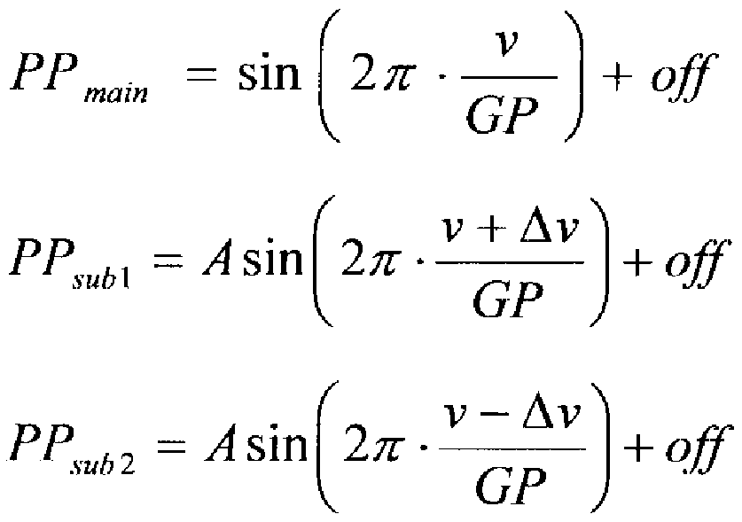 v
v
DPP ^ \ - os 2π - •sin 2π■ ぱ 7
GP GP
[0051] ただし、「v」は、光ディスク 50におけるデータが記録されているトラック中心力も測つ た 0次回折光によって形成されるビームスポットの半径方向における位置を示し、「 Δ v」は、光ディスク 50上における 0次回折光によって形成されるビームスポットから測つ た ± 1次回折光によって形成されるビームスポットの当該光ディスク 50の半径方向に おけるシフト量を示す。また、「off」とは、対物レンズ 300の光ディスク 50の半径方向 の移動に伴いディテクタ 270上のスポットが当該ディテクタ 270の分割線と垂直な方
向にずれることで生じるプッシュプルオフセットを示す。
[0052] 一方、一般的には、理想状態では、(式 8)に示すように、上述の(式 7)において、「
Av=GPZ2」となるように回折格子 230の角度を調整するようになっている力 例え ば、光ディスク 50の回転軸と当該光ディスク 50に形成されたトラックの中心が一致し ない場合に、または、図 3 (a)に示すように、対物レンズ 300が光ディスク 50の半径方 向に移動するためのスライダ軸上にないなど、当該対物レンズ 300が光ディスク 50の トラックに垂直な軸上に設置されていない場合には、「Δν」は、「GP/2」の値力もず れてしまうので、(式 8)を満たさなくなり、 DPP振幅力「Av」の値によって変動してしま う(図 3 (b)参照)。
[数 5]
(式 8 )

[0053] そこで、本実施形態では、後述するように、回折格子 230を特殊形状にて形成する ことによって、 DPP信号振幅の変動を抑制し、かつ、プッシュプルオフセットをキャン セルすることができる当該トラッキングエラー信号を得ることができるようになつている 。また、回折格子 230の構造を縦方向、横方向とも周期構造にすることで,光ピックァ ップ装置の組み立て時に回折格子の位置調整を不要にしている。
[0054] 具体的には、本実施形態の回折格子 230には、図 3に示すように、当該光ディスク 50のトラック方向に一定の周期にて溝が設けられ、光ディスク 50の半径方向に所定 のピッチ Ρにて交互に並設された第 1の格子溝 (以下、「第 1格子溝」という。) 231と 第 2の格子溝 (以下、「第 2格子溝」という。) 232の 2種類の格子溝が設けられており 、第 2格子溝 232のトラック方向の周期(以下、「溝周期」という。)が、第 1格子溝 231 の溝周期に対して「1/2」または「1/4」シフトさせて構成されて!、る。
[0055] そして、この回折格子 230において、光ディスク 50の盤面に設けられたグループの ピッチ(以下、「グループピッチ」という。)を「0?」、光ビームの有効径を「D」、当該光 ビームの波長を「え」および対物レンズ 300の開口数を「NA」とすると、第 1格子溝 23 1および第 2格子溝 232の並設されるピッチ (以下、「並設ピッチ」という。 )「P」は、溝 周期を「1Z2」シフトさせる場合には、(式 1)として規定され、また、溝周期を「1Z4」
シフトさせる場合には、(式 2)として規定されるようになって!/、る。
[数 1]
P— ス
(2n + \) - GP - NA . · . (式 i )
[数 2]
P—
(4n + 2) - GP - NA . ■ , (式2 )
[0056] なお、光ビームの有効径 Dとは、対物レンズ 300で利用される光束径に相当し、「n 」は、自然数を示す。また、この本実施形態において規定される並設ピッチ「P」の詳 細については後述する。
[0057] 本実施形態では、光ピックアップ装置 200にお ヽて、このような特殊形状を有する 回折格子 230を用いることによって、 ± 1次回折光が光ディスク 50にて反射されディ テクタ 270に検出され、当該検出された ± 1次回折光の受光信号に基づいて、上述 のように、ァクチユエータサーボ回路 140にて差分信号 PP および PP を算出し、 subl sub 2 当該算出された各差分信号に基づいてトラッキングエラー信号を算出すると、 ± 1次 回折光のプッシュプル信号振幅を抑制し、かつ、プッシュプルオフセットをキャンセル 可能な当該トラッキングエラー信号を得ることができるようになつている。なお、本実施 形態では、上述の回折格子 230を液晶パネルで実現することも可能である。
[0058] 次に、本実施形態の回折格子 230において第 1格子溝 231および第 2格子溝 232 が並設される並設ピッチ「P」につ 、て説明する。
[0059] まず、本実施形態の並設ピッチ「P」について説明する前に、図 4〜図 7を用いて( 式 9)に示す並設ピッチ Pにて (式 9)中の自然数「m」を大きくすることによって単純に 並設ピッチ「P」を小さくした場合におけるプッシュプル信号振幅のシミュレーション結 果について説明する。ただし、(式 9)において「D」は前述した有効径を示す。
[数 6]
― m ( mは自然数) ' ' · (式 9 )
[0060] なお、図 4〜図 7は、並設ピッチ「P」を (式 9)で定義した場合におけるプッシュプル 信号振幅をシミュレーションした結果を示す図であり、格子溝に対するプッシュプル 信号振幅の値を示すグラフ (I)である。ただし、図 4〜図 7とも、第 1格子溝 231と第 2 格子溝 232の繰返し周期、すなわち、「2P」の長さに対して回折格子 230の対物レン ズに対する位置ずれを 0%〜25%まで 5%毎に変化させ、横軸に並設ピッチ「P」、縦 軸に正規ィ匕したプッシュプル振幅の値を示したグラフである。
[0061] また、以下の説明において、図 4および図 5に示すシミュレーション結果においては 、光ディスク 50として BD— REを想定し、開口数「NA=0. 85」、光ビームの波長「え =0. 405 m」、グループピッチ「GP = 0. 32 m」および有効径「0= 3. Omm」を 用いている。また、図 6および図 7に示すシミュレーション結果においては、光ディスク 50として DVD— RAMを想定し、開口数「NA=0. 6」、光ビームの波長「え =0. 65 /z m」、グループピッチ「GP= 1. 48 m」および有効径「0 = 3. Omm」を用いてい る。
[0062] DPP信号振幅の変動は、(式 7)の Δνの変化によって生じる。(式 7)の Δνを消去 する為には、(式 5)および (式 6)で示される ± 1次回折光によるプッシュプル信号振 幅を抑制すれば良い。したがって、 DPP信号振幅の変動を抑制する為には、(式 9) に示す並設ピッチ「Ρ」にて (式 9)中の自然数「m」を大きくすることによって当該並設 ピッチ「P」を小さくした場合にぉ 、て、光ピックアップ装置の組み立て時に回折格子 の位置調整を必要とせず、士 1次回折光によるプッシュプル信号振幅を抑制できるか 否かが問題となる。
[0063] し力しながら、図 4〜図 7に示すように、回折格子 230における第 1格子溝 231の(ト ラック方向の)溝周期を「1Z2」シフトさせた場合、すなわち、位相差「π」を与えた場 合であっても、または「1Ζ4」シフトさせた場合、すなわち、位相差「π Ζ2」を与えた 場合であっても、ある特定の並設ピッチ「Ρ」ではプッシュプル振幅が抑制されるもの の、この場合において、その他の並設ピッチ「Ρ」ではプッシュプル振幅を抑制するこ
とができない。また、回折格子 230の位置ずれについても、特定の位置ずれに対して はプッシュプル振幅を抑制することができても、他の位置ずれが発生した場合にはプ ッシュプル振幅を抑制することができな 、。
[0064] そこで、本実施形態では、以下に説明するように、並設ピッチ「P」が(式 1)および( 式 2)の関係性を有している場合に,最も効果的にプッシュプル振幅を抑制すること ができるようになつている。以下ではそれについて詳細に説明する。
[0065] 図 8〜図 15を用いて本実施形態における並設ピッチについて説明する。なお、図 8 〜図 15は、本実施形態の回折格子の第 1格子溝 231および第 2格子溝 232が並設 される並設ピッチ「P」について説明するための図であり、図 16および図 17は、本実 施形態の所定の並設ピッチにおいて第 1格子溝および第 2格子溝 232が配設された 回折格子にお 、て、格子溝に対するプッシュプル信号振幅の値を示すグラフである
[0066] 以下の説明において、光ディスク 50に照射される各回折光、すなわち、光ビームに 対して、当該光ディスク 50の盤面上にて回折される回折光を反射回折光といい、回 折格子 230によって回折される各回折光とは区別して説明する。また、以下の説明 において、 0次回折光および士 1次回折光のそれぞれに対して 0次反射回折光およ び士 1次反射回折光が発生するようになって!/、る。
[0067] なお、以下の説明では、 1次回折光、すなわち、 1次のビームスポットを形成す る光ビームを例にして説明する。また、以下の説明において、対物レンズ 300面上で の座標におけるトラック方向を「x」、半径方向を「y」とする。
[0068] 対物レンズ 300に入射する光ビームは、振幅分布を f (x、 y)、位相分布を φ (x、 y) とすると、入射光の対物レンズ 300面上においては、(式 10)にて表される複素振幅 分布を有する。また、対物レンズ 300の瞳の半径を「1」とすれば、入射光が一様の強 度光の場合には、 f (x、 y)を (式 11)に示す関数にて表すことができる。
[数 7]
(式 1 0
(式 1 1 )

[0069] 上述のように、各回折光である光ビームは、光ディスク 50においても、回折されるた め、スカラー回折理論に従うと、当該 1次の光ビームにおける 0次反射回折光およ び士 1次反射回折光の複素振幅分布は、(式 12)〜(式 14)によって表される。
[数 8]
0次反射回折光 :
Ε0 ^ /{χ, γ)&χρ [- ίφ(χ, γ)] (式 1 2 )
+ 1次反射回折光 :
(式 1 3 )
 一 1次反射回折光 : 一 1 (式 1 4 )

ただし、
, NA \
q≡ GP
(式 1 5 )
V λ ノ
[0070] なお、「ΝΑ」、「え」、「GP」、「v」は、上述と同様に、それぞれ、対物レンズ 300の開 口数、光ビームの波長、光ディスク 50のグループピッチおよび当該光ディスク 50上 に形成されるビームスポットの半径方向位置を示し、「H」は、光ビームの波長および グループの深さなどの所定の値で決定される当該光ディスク 50で反射回折された 0 次反射回折光と ± 1次反射回折光の位相差を示す。
[0071] そして、上述の(式 12)〜(式 15)を用いて、図 8および図 9に示す 1次の光ビーム における 0次反射回折光と ± 1次反射回折光がディテクタ 270において重なる、すな わち、干渉する領域である「S 」領域および「S 」の領域における強度「Is 」および「I
s 」は、(式 3)〜(式 15)にて算出される。
-1
[数 9]

■ · · (式 1 6 ) ただし、
2

- · · (式 1 8 ) ただし
ν
χ , y + Β = -Η +2π (式 1 9 )
GP また、 0次光と ± 1次光が干渉しない領域、すなわち、図 8および図 9において「S」
0 領域の光強度「Is」は、(式 20)に示すように、 (1. 0)と算出される。
0
[数 10]
 1 .0 (式 2 0 ) 光ディスク 50にて反射回折された反射回折光は、再び対物レンズ 300を通りディテ クタ 270上にビームスポットを形成するが、当該ディテクタ 270上でのスポット強度分 布は、対物レンズ 300上での強度分布とほぼ同じ、すなわち、相似形として考えるこ とができるため、ディテクタ 270における 2分割の受光素子によって得られるプッシュ プル信号 ΡΡは(式 21)にて表すことができる。
[数 11]
PP = sjs+、 S—、IS +s (式 2 1 )
[0074] ただし、「S 」および「S 」は、「S 」領域または「S 」領域の面積を示す。また、「δ
+1 - 1 +1 - 1
」は、図 8および図 9に示すように、隣接する受光素子に入光する「S」領域の面積の
0
差分を示し、上述のプッシュプルオフセットを表して 、る。
[0075] このように、プッシュプル信号 PPは、干渉領域の面積と、当該干渉領域の光強度に 基づいて算出することができるので、本実施形態では、上述の(式 17)および (式 19) における φ (x、 y)、すなわち対物レンズ 300面上での入射光の位相分布を工夫する こと〖こよって、上述の効果を得る回折格子 230を構成している。
[0076] ここで、以下において、上述の位相分布 φ (x、 y)に具体的な値を与えて説明する。
[0077] まず、当該回折格子 230による 0次回折光について説明する。
0次回折光は、当該回折格子 230に入射する光と同じ複素振幅分布となる。したが つて、当該回折格子 230に入射される光の位相分布が場所に寄らず一様な値、すな わち、「 φ (x、 y) = φ 」とすると、上述の(式 16)〜(式 19)は、 (式 22)〜(式 24)のよ
0
うに表される。
[数 12] φ+]
 - 0 (式 2 2 )
( V
I s - 2 + 2 cos A - 2 + 2 cos Η + 2π
GP (式 2 3 )
V
( V
I - 2 + 2 cos B = 2 + 2 cos Η - 2π
V GP (式 2 4
[0078] また、通常、「S = S 」であるので、「S = S ≡S士」とおくと、(式 21)から、最終
+1 - 1 +1 - 1 1
的に 0次回折光のプッシュプル信号 PP 力 (式 25)となり、当該 0次回折光のプッシ main
ュプル信号 PP は、光ディスク 50上のビームスポット位置 (V)の sin波として得られる main
こととなる。
[数 13]
ί V f v
PP m.ain = 2S^ cos H + 2π cos H— 2π + δ
V GP V GPノ J
-2S±i sin H sin 2π + δ
GP
(式 2 5 )
[0079] 次に、当該回折格子 230による ±1次回折光について説明する。
±1次回折光のプッシュプル信号 ΡΡ
subは、当該回折格子 230による ±1次回折光 の位相が格子溝のずれ量に比例するため、当該回折格子 230に入射する一様の光 ビームの位相を「φ 」とすると, ±1次回折光の位相分布() 、 )は、(式 26)として
0
表される。
[数 14] , 0 + 2π -^^-= 0 + Αφ(γ) (式 2 6 ただし、
Δ ア)
Α φ (^y I≡ 2 π
s
[0080] なお、この「s」は、上述の格子溝の溝周期を示し、光ディスク 50上に形成される 3ビ ームのスポット中心の距離によって決定される。また、「As(y)」は、溝周期のずれ量 分布を表す関数であり、図 10に示すように、(式 27)によって表すことができる。
[数 15]
 (式 2
(式 2
[0081] ただし、「i」は、整数を示し、「 *」は、畳み込み演算を示す。また、「 δ (y)」および「 Rect(y, P)」はそれぞれデルタ関数、レクタンダル関数と言われるものであり、(式 28 )および (式 29)にて定義される。
[数 16]
1
0 if y≠

Rect (y,P) (式 2 9 )
0… if\y \ >―
1 1 2
[0082] 例えば、 BD— REの光ディスク 50に当該回折格子 230を適用し、上述の(式 1)ま たは (式 2)に示すように、回折格子 230における第 1格子溝 231と第 2格子溝 232の 溝周期のずれと、第 1格子溝 231と第 2格子溝 232の並設ピッチ「P」とを規定すると、 以下のように ±1次回折光におけるプッシュプル信 PPが算出されることになる。
[0083] この場合に、 BD—REの光ディスク 50におけるデータの記録または再生に用いら れる開口数が「NA=0.85」、光ビームの波長が「え =0.405 m」およびグループ ピッチが「GP = 0.32/ζπι」となるので、(式 15)より、以下に示す「q」は、「0.672」と なる。
[0084] (1)回折格子 230における第 1格子溝 231と第 2格子溝 232の溝周期のずれ「AsZ s」が「1/2」であり、かつ、第 1格子溝 231と第 2格子溝 232の並設ピッチが「P = D Z{(2n+l)'q}」の場合 (nは自然数)
例えば「n=5」とすると、本実施形態の回折格子 230から出射される ±1次回折光 は、図 11に示す位相分布「φ (x、 y)」を有することとなり、当該 ±1次回折光が光ディ スク 50により反射回折され、再び対物レンズ 300に入射されると、図 12に示す各回 折反射回折光の波面の位相分布を構成することとなる。また、図 8および図 9に示し た干渉領域における「S 」領域および「S 」領域では、位相分布「φ 」および「φ 」
+1 -1 +1 -1 は、「+π」、「0」、「一 π」の 3値のうち何れ力となる。
[0085] そこで、「S 」領域のうち「φ =+π」、「φ =0」、「φ =— π」となる領域の面積
+1 +1 +1 +1
を、それぞれ「(S ) + 7u」、「(S )。」、「(S )— π」とし、「S 」領域のうち「φ =+π」、
+1 +1 +1 - 1 - 1
「φ =0」、「φ =— π」となる領域の面積を、それぞれ「(S ) + π」、「(S )。」、「(S
-1 -1 -1 -1 -1
)_π」とすると、(式 21)から ±1次回折光におけるプッシュプル信号 PP は、(式 30)
sub
にて表されることとなる。
[0086] ただし、「(I ) φ」は、「S」領域のうち位相が「 φ」となる領域の光強度を示している。
s
[数 17] ppsub : {(^+) γπ - {is +n + (s+: )° - (/ϊ+ι )° + (s+l - s+] }
- { _,广■ ( 】广 + (S_, )° . (/ , )° + (S , · ,广 }+ δ
• · · (式 3 0)
[0087] このような条件下において、まずは、対物レンズ 300上での位相分布が光ディスク 5
0の半径方向に対称になるように回折格子 230が設置された場合を考える。
[0088] ±1次回折光が光ディスク 50により反射回折され、再び対物レンズ 300に入射され ることで、図 8に示すように、各「S」領域は、(式 31)および (式 32)にて表される関係 性を有する。
[数 18] °+i) -
 . · · (式 3 1 ) ( 十】) 1ノ (S±l/ - ' ' ぱ3 2 )
[0089] したがって、(式 16)〜(式 19)式を用いると、(式 31)により ±1次回折光における プッシュプル信号 PP は、(式 33)〖こて表されること〖こなる。
sub
[数 19]
}丄fl。.^(^{j^{^) () ( ¾) (^ζ (i+5+sso。¾ +ssso。s + =0。80。,l—--一
善( N T

[0090] ここで、図 12から分かるように、「2 (S± 1 ) ± π (S士 1)°」であるので、(式 33)に示 すプッシュプル信号 ΡΡ は、「ν」に依存せず、「 δ」の近似値となる。
sub
[0091] 一方、対物レンズ 300上での位相分布が光ディスク 50の半径方向に常に対称にな るとは限らない。そこで、次に対物レンズ 300上での位相分布が光ディスク 50の半径 方向に PZ2だけずれるように回折格子 230が設置された場合を考える。
[0092] このような条件下において、 ± 1次回折光が光ディスク 50により反射回折され、対物
レンズ 300に入射されると、図 9に示す各回折反射回折光の波面の位相分布を構成 することとなる。このとき、この図 9に示すように、各「S」領域は(式 34)〜(式 36)にて 表される関係性を有する。
[数 20]
≡(s±l)±7r • · · (式 3 4 ) 二 —〗广 - - - (式 3 5 )
= — ,)o ≡ (S±])° —— . (式 3 6 ) したがって、(式 16)〜(式 19)式を用いると、(式 31)により ±1次回折光における プッシュプル信号 PP は、(式 37)にて表される。
sub
[数 21]
卜

[0094] ここで、図 13から分かるように、(式 38)の関係が成り立つので、(式 37)に示すプッ シュプル信号 PP は、「v」に依存せず、「 δ」の近似値となる。
sub
[数 22]
^ (^±1 ) - - . (式 3 8 )
[0095] 以上示したように,回折格子 230における第 1格子溝 231と第 2格子溝 232の溝周
期のずれ「A sZs」が「1Z2」であり、かつ、第 1格子溝 231と第 2格子溝 232の並設 ピッチが「P = DZ{ (2n+ l) 'q}」の場合は、対物レンズ 300と回折格子 230が光デ イスク 50の半径方向に対して相対的にずれていてもプッシュプル信号 PP は、「v」 sub
に依存せず、「 δ」の近似値となる。
[0096] (2)回折格子 230における第 1格子溝 231と第 2格子溝 232の溝周期のずれ「A sZ s」が「1/4」であり、かつ、第 1格子溝 231と第 2格子溝 232の並設ピッチが「P = D Z { (4n + 2) · q }」の場合 (nは自然数)
例えば、「n=3」とすると、 ± 1次回折光が光ディスク 50により反射回折され、再び 対物レンズ 300に入射されることで、図 14に示す各回折反射回折光の波面の位相 分布を構成することとなる。また、図 8および図 9に示した干渉領域における「S 」領
+1 域および「S 」領域では、位相分布「φ 」および「φ 」は、「
- 1 +1 - 1 + π Ζ2」、「一 π Ζ2」 のうち何れかとなる。
[0097] そこで、「S 」領域のうち「 φ = + π
+1 +1 Ζ2」、「 φ = - π
+1 /2jとなる領域の面積を、 それぞれ「(S ) + π /2」、「(S )— π /2」とし、「S 」領域のうち「φ = + π /2」、「φ =
+1 +1 - 1 - 1 - 1
— π Ζ2」となる領域の面積を、それぞれ「(S ) + π /2」、「(S )— π /2」とすると、(式 21)
- 1 - 1
式から ± 1次回折光におけるプッシュプル信号 PP は、(式 39)にて表されることとな
sub
る。ただし、「(Is± ) φ」は、「S」領域のうち位相が「φ」となる領域の光強度を示し ている。
[数 23]
+
() ^ ε

[0098] このような条件下において、まずは、対物レンズ 300上での位相分布が光ディスク 5 0の半径方向に対称になるように回折格子 230を設置された場合を考える。
[0099] ± 1次回折光が光ディスク 50により反射回折され、対物レンズ 300に入射されること で、図 10に示すように、各「S」領域は、(式 40)にて表される関係性を有する。
[数 24]
(S 2 =(S 2 =( J 2 = (^) 2 2 . . . (式 4 0 ) (/ ΐ一
したがって、(式 16)〜(式 19)式を用いると、(式 40)により ± 1次回折光における プッシュプル信 /号 PP は、(式 41)にて表されることになり、この場合おいても、(式 4
sub
1)に示すプッシュプル信号 PP は、「v」に依存せず、「
sub δ」の近似値となる。
[数 25] M寸
ノ へ

I <
ノ
[0101] 一方、対物レンズ 300上での位相分布が光ディスク 50の半径方向に常に対称にな るとは限らない。そこで、次に対物レンズ 300上での位相分布が光ディスク 50の半径 方向に PZ2だけずれるように回折格子 230が設置された場合を考える。
[0102] このような条件下において、 ±1次回折光が光ディスク 50により反射回折され、対物 レンズ 300に入射されると、図 15に示す各回折反射回折光の波面の位相分布を構 成することとなる。すなわち、この図 15に示すように、各「S」領域は(式 42)および (式 43)にて表される関係性を有する。
[数 26]
2 ≡(S±]) . . . ぱ 4 2)
(S '
 ≡(S± J . . . (式 4 3 ) したがって、(式 16)〜(式 19)式を用いると、(式 42)により ±1次回折光における プッシュプル信号 PP は、(式 44)〖こて表されること〖こなる。
sub
[数 27]


[0104] ここで,図 15から分かるように、(式 45)にて表すことができるので、(式 44)に示す プッシュプル信号 PP は、「v」に依存せず、「 δ」の近似値となる。
sub
[数 28]
+ π
( ±1 ) 2 ^ (^±1) … (式 4 5 )
[0105] このように、回折格子 230において、第 1格子溝 231と第 2格子溝 232の溝周期を「 1/2」または「1/4」シフトさせ、当該各第 1格子溝 231および第 2格子溝 232の並
設ピッチ Pを (式 1)または (式 2)とすることによって、上述のように、 ± 1次回折光のプ ッシュプル信号 PP を算出することができるようになつている。
sub
[0106] すなわち、本実施形態の回折格子 230を、 BD—REの光ディスク 50におけるデー タの再生時に適用すると、上述の(式 1)おまたは (式 2)に示すように、回折格子 230 における第 1格子溝 231と第 2格子溝 232の溝周期を「1Z2」シフトさせた場合、すな わち、位相差「π」を与えた場合であっても、または「1Ζ4」シフトさせた場合、すなわ ち、位相差「π Ζ2」を与えた場合であっても、図 16および図 17に示すように、「η= 3 」以上に設定すれば、回折格子 230の位置ずれ、すなわち、当該回折格子 230の対 物レンズ 300における X軸および y軸調整におけるずれが発生したとしても、プッシュ プル振幅が抑制されるようになって 、る。
[0107] したがって、士 1次回折光だけ、プッシュプルオフセットは、保存される一方、プッシ ュプル信号振幅は抑制する、すなわち、ほぼゼロになるので、本実施形態では、光ピ ックアップ装置 200において、このような回折格子 230を用い、 DPPトラッキング法を 用いることによって、プッシュプルオフセットをキャンセルしつつ、プッシュプル信号振 幅、すなわち、トラッキングエラー信号振幅の変動を圧縮することができるようになつ ている。
[0108] なお、図 16および図 17に示すシミュレート結果は、対物レンズの開口数「NA=0.
85」、光ビームの波長「え =0. 405 111」、グノレープピッチ「0? = 0. 32 m」および ビーム有効径¾ = 3. Omm」を用い、第 1格子溝 231の格子幅 W1と第 2格子溝 232 の格子幅 W2は同一として行ったものである。また、図 16および図 17は、第 1格子溝 231の格子幅 W1と第 2格子溝 232の格子幅 W2を足した値、すなわち、 2W1にて正 規ィ匕した回折格子 230の位置ずれを 0%〜25%まで 5%毎に変えて、横軸は格子 溝幅、縦軸は正規ィ匕したプッシュプル振幅の値にて示したグラフである。
[0109] 以上本実施形態の光ピックアップ装置 200は、光ディスク 50に対して光ビームを照 射し、当該光ディスク 50に記録されたデータの読み出し、または、当該光ディスク 50 に対するデータの記録の少なくとも何れか一方を行う光ピックアップ装置 200であつ て、光ディスク 50に記録されたデータの読み出し、または、当該光ディスク 50に対す るデータの記録の少なくとも何れか一方を行う際に、光ビームを照射する光源部 210
と、光源部 210から出射された光ビームを回折し、少なくとも 0次回折光、 + 1次回折 光および 1次回折光を光ディスク 50に出射する回折格子 230と、各回折光を光デ イスク 50に集光するための対物レンズ 300と、光ディスク 50にて反射された各回折光 を受光して各受光信号を出力するディテクタ 270と、各受光信号に基づ 、て対物レ ンズ 300の光ディスク 50に対する位置を制御するァクチユエータ 250と、を備え、回 折格子 230には、当該光ディスク 50の半径方向に光ディスク 50の盤面に設けられた グループピッチを「GP」、対物レンズ 300における光ビームの有効径を「D」、当該光 ビームの波長を「え」および対物レンズ 300の開口数を「NA」とした場合に、第 1格子 溝 231および第 2格子溝 232が(式 1)を具備するピッチ「P」にて並設されているとと もに、第 1格子溝 231および第 2格子溝 232が、それぞれ、光ディスク 50におけるデ ータが記録されるトラック方向に一定の周期にて構成された溝を有し、一の格子溝の トラック方向の溝が、他の格子溝の溝の周期に対して「1Z2」シフトされて構成されて いる。
[0110] この構成により,本実施形態の光ピックアップ装置 200は、特殊形状の回折格子 23 0を用いることによって生じた ± 1次回折光を,光ディスク 50に照射させ、その反射回 折光をディテクタ 270にて検出する際, 0次反射回折光と ± 1次反射回折光が干渉 する領域において,光強度を強める領域と弱める領域がほぼ等しくなり,結果として プッシュプル信号振幅はほぼゼロになる。また対物レンズ 300と特殊形状の回折格 子 230の相対位置が変化しても反射回折光における光強度を強める領域と弱める領 域の割合はほとんど変化しな 、。
[0111] この結果、本実施形態の光ピックアップ装置 200は、差動プッシュプル信号にて、 ァクチユエータ 250を介して対物レンズ 300を制御すれば、組み立て時に回折格子 2 30の位置調整を不要にするとともに、光ディスク 50上でのメインビームとサブビーム の半径方向の位置が変化することによって生じる差動プッシュプル信号振幅の変動 を抑制しつつ、対物レンズ 300の当該光ディスク 50の半径方向におけるシフト量によ つて生ずる対物レンズ 300のトラッキングエラーを抑制することができる。
[0112] また、本実施形態の光ピックアップ装置 200は、光ディスク 50に対して光ビームを 照射し、当該光ディスク 50に記録されたデータの読み出し、または、当該光ディスク 5
0に対するデータの記録の少なくとも何れか一方を行う光ピックアップ装置 200であつ て、光ディスク 50に記録されたデータの読み出し、または、当該光ディスク 50に対す るデータの記録の少なくとも何れか一方を行う際に、光ビームを照射する光源部 210 と、光源部 210から出射された光ビームを回折し、少なくとも 0次回折光、 + 1次回折 光および 1次回折光を光ディスク 50に出射する回折格子 230と、各回折光を光デ イスク 50に集光するための対物レンズ 300と、光ディスク 50にて反射された各回折光 を受光して各受光信号を出力するディテクタ 270と、各受光信号に基づ 、て対物レ ンズ 300の光ディスク 50に対する位置を制御するァクチユエータ 250と、を備え、回 折格子 230には、当該光ディスク 50の半径方向に光ディスク 50の盤面に設けられた グループピッチを「GP」、対物レンズ 300における光ビームの有効径を「D」、当該光 ビームの波長を「え」および対物レンズ 300の開口数を「NA」とした場合に、第 1格子 溝 231および第 2格子溝 232が(式 2)を具備するピッチ「P」にて並設されているとと もに、第 1格子溝 231および第 2格子溝 232が、それぞれ、光ディスク 50におけるデ ータが記録されるトラック方向に一定の周期にて構成された溝を有し、一の格子溝の トラック方向の溝が、他の格子溝の溝の周期に対して「1Z4」シフトされて構成されて いる。
[0113] この構成により、本実施形態の光ピックアップ装置 200は、特殊形状の回折格子 23 0を用いることによって生じた ± 1次回折光を、光ディスク 50に照射させ、その反射回 折光をディテクタ 270にて検出する際、 0次反射回折光と ± 1次反射回折光が干渉 する領域において、光強度を強める領域と弱める領域がほぼ等しくなり、結果として プッシュプル信号振幅はほぼゼロになる。また対物レンズ 300と特殊形状の回折格 子 230の相対位置が変化しても反射回折光における光強度を強める領域と弱める領 域の割合はほとんど変化しな 、。
[0114] この結果、本実施形態の光ピックアップ装置 200は、差動プッシュプル信号にて、 ァクチユエータ 250を介して対物レンズ 300を制御すれば、組み立て時に回折格子 2 30の位置調整を不要にするとともに、光ディスク 50上でのメインビームとサブビーム の半径方向の位置が変化することによって生じる差動プッシュプル信号振幅の変動 を抑制しつつ、対物レンズ 300の当該光ディスク 50の半径方向におけるシフト量によ
つて生ずる対物レンズ 300のトラッキングエラーを抑制することができる。
[0115] なお、本実施形態の光ピックアップ装置 200は、記録フォーマットが異なる光デイス ク 50に対して情報の記録および再生を行う際にも用いることができる。例えば、図 18 に示すように、(式 1)および (式 2)により、並設ピッチ Pを (式 46)とすると、 DVD-R AMに対しては、「a = 9」、 DVD— RWに対しては、「a= 17」とすることによって、並 設ピッチ Pにほぼ同一の値を用いることができる。
[数 29] a GP - NA . · ■ (式 4 6 ) ただし、
a = (2 n + \ ) または " = (4" + 2) ( nは自然数)
[0116] すなわち、異なる記録フォーマットの条件にて定めた並設ピッチ Pの値を有する回 折格子 230を用いれば、一つの回折格子 230によって異なる記録フォーマットの光 ディスク 50に対しても適用することができる。ただし、例えば、 DVD— RAMに対して 「a = 14」、 DVD—RWに対して「a = 28」など「a」の値を大きくして成立する場合もあ るが、当該「a」を大きくすると、必然的に並設ピッチ「P」が小さくなるので、回折格子 の製造精度との関係で「a」を選択することが必要になる。また、図 18は、 DVD-RA Mおよび DVD— RWにおける「a」に対する並設ピッチ「P」を示すグラフである。
Claims
[数 1]
P—
(2n ^ \) GP NA . · . (式 の式を具備するピッチ pにて並設されているとともに、
前記第 1格子溝および前記第 2格子溝が、それぞれ、前記光学式記録媒体におけ るデータが記録されるトラック方向に一定の周期にて構成された溝を有し、
一の格子溝のトラック方向の溝が、他の格子溝の溝の周期に対して 1Z2シフトされ
て構成されていることを特徴とする光ピックアップ装置。
光学式記録媒体に対して光ビームを照射し、当該光学式記録媒体に記録されたデ ータの読み出し、または、当該光学式記録媒体に対するデータの記録の少なくとも 何れか一方を行う光ピックアップ装置であって、
前記光学式記録媒体に記録されたデータの読み出し、または、当該光学式記録媒 体に対するデータの記録の少なくとも何れか一方を行う際に、光ビームを照射する光 源と、
前記光源から出射された光ビームを回折し、少なくとも 0次回折光、 + 1次回折光お よび 1次回折光を光学式記録媒体に出射する回折格子と、
前記各回折光を前記光学式記録媒体に集光するための集光手段と、
前記光学式記録媒体にて反射された前記各回折光を受光して各受光信号を出力 する受光手段と、
前記各受光信号に基づいて前記集光手段の前記光学式記録媒体に対する位置 を制御する制御手段と、
を備え、
前記回折格子には、当該光学式記録媒体の半径方向に前記光学式記録媒体の 盤面に設けられたグループピッチを GP、前記集光手段における光ビームの有効径 を D、当該光ビームの波長をえおよび開口数を NA、 nを自然数とした場合に、第 1格 子溝および第 2格子溝が、前記光学式記録媒体におけるデータが記録されるトラック 方向に垂直な方向に、
[数 2]
P— ^
(4n + 2) - GP - NA ' , ■ (式2 ) の式を具備するピッチ pにて並設されているとともに、
前記第 1格子溝および前記第 2格子溝が、それぞれ、前記光学式記録媒体におけ るデータが記録されるトラック方向に一定の周期にて構成された溝を有し、
一の格子溝のトラック方向の溝が、他の格子溝の溝の周期に対して 1Z4シフトされ
て構成されていることを特徴とする光ピックアップ装置。
[3] 請求項 1または 2に記載の光ピックアップ装置であって、
前記制御手段が、差動プッシュプル方式にて前記各受光信号に基づ!、て前記集 光手段の前記光学式記録媒体に対する位置を制御することを特徴とする光ピックァ ップ装置。
[4] 請求項 1乃至 3に記載の光ピックアップ装置であって、
前記回折格子が液晶パネルにて構成されていることを特徴とする光ピックアップ装 置。
Priority Applications (2)
| Application Number | Priority Date | Filing Date | Title |
|---|---|---|---|
| JP2007525932A JP4663723B2 (ja) | 2005-07-22 | 2006-07-03 | 光ピックアップ装置 |
| US11/996,430 US7821899B2 (en) | 2005-07-22 | 2006-07-03 | Optical pickup device |
Applications Claiming Priority (2)
| Application Number | Priority Date | Filing Date | Title |
|---|---|---|---|
| JP2005213138 | 2005-07-22 | ||
| JP2005-213138 | 2005-07-22 |
Publications (1)
| Publication Number | Publication Date |
|---|---|
| WO2007010737A1 true WO2007010737A1 (ja) | 2007-01-25 |
Family
ID=37668621
Family Applications (1)
| Application Number | Title | Priority Date | Filing Date |
|---|---|---|---|
| PCT/JP2006/313244 Ceased WO2007010737A1 (ja) | 2005-07-22 | 2006-07-03 | 光ピックアップ装置 |
Country Status (3)
| Country | Link |
|---|---|
| US (1) | US7821899B2 (ja) |
| JP (1) | JP4663723B2 (ja) |
| WO (1) | WO2007010737A1 (ja) |
Cited By (1)
| Publication number | Priority date | Publication date | Assignee | Title |
|---|---|---|---|---|
| JP2007122792A (ja) * | 2005-10-26 | 2007-05-17 | Sanyo Electric Co Ltd | 回折格子、光ピックアップ装置 |
Families Citing this family (3)
| Publication number | Priority date | Publication date | Assignee | Title |
|---|---|---|---|---|
| JP2009158042A (ja) * | 2007-12-27 | 2009-07-16 | Panasonic Corp | 光ピックアップ装置及び光検出器 |
| JP2009223937A (ja) * | 2008-03-14 | 2009-10-01 | Ricoh Co Ltd | 光ピックアップおよびこれを用いる光情報処理装置 |
| JP5178339B2 (ja) * | 2008-06-20 | 2013-04-10 | 三洋電機株式会社 | 光ピックアップ装置 |
Citations (5)
| Publication number | Priority date | Publication date | Assignee | Title |
|---|---|---|---|---|
| JPH11296875A (ja) * | 1998-02-16 | 1999-10-29 | Hitachi Ltd | 光ヘッドおよび光ディスク装置 |
| JP2003162831A (ja) * | 2001-11-27 | 2003-06-06 | Sharp Corp | 光ピックアップ装置 |
| JP2004086957A (ja) * | 2002-08-23 | 2004-03-18 | Sharp Corp | 光ピックアップ装置 |
| JP2004095077A (ja) * | 2002-08-30 | 2004-03-25 | Sharp Corp | 光ピックアップ装置 |
| JP2005100550A (ja) * | 2003-09-26 | 2005-04-14 | Sony Corp | 光ピックアップ及び光ディスク記録再生装置 |
Family Cites Families (3)
| Publication number | Priority date | Publication date | Assignee | Title |
|---|---|---|---|---|
| TW444201B (en) * | 1998-02-16 | 2001-07-01 | Hitachi Ltd | Optical head |
| JP3527705B2 (ja) | 1999-12-28 | 2004-05-17 | シャープ株式会社 | 光ピックアップ及びトラッキングサーボ方法 |
| JP2005353187A (ja) * | 2004-06-11 | 2005-12-22 | Nec Corp | 光ヘッド装置及び光学式情報記録再生装置 |
-
2006
- 2006-07-03 US US11/996,430 patent/US7821899B2/en not_active Expired - Fee Related
- 2006-07-03 WO PCT/JP2006/313244 patent/WO2007010737A1/ja not_active Ceased
- 2006-07-03 JP JP2007525932A patent/JP4663723B2/ja not_active Expired - Fee Related
Patent Citations (5)
| Publication number | Priority date | Publication date | Assignee | Title |
|---|---|---|---|---|
| JPH11296875A (ja) * | 1998-02-16 | 1999-10-29 | Hitachi Ltd | 光ヘッドおよび光ディスク装置 |
| JP2003162831A (ja) * | 2001-11-27 | 2003-06-06 | Sharp Corp | 光ピックアップ装置 |
| JP2004086957A (ja) * | 2002-08-23 | 2004-03-18 | Sharp Corp | 光ピックアップ装置 |
| JP2004095077A (ja) * | 2002-08-30 | 2004-03-25 | Sharp Corp | 光ピックアップ装置 |
| JP2005100550A (ja) * | 2003-09-26 | 2005-04-14 | Sony Corp | 光ピックアップ及び光ディスク記録再生装置 |
Cited By (1)
| Publication number | Priority date | Publication date | Assignee | Title |
|---|---|---|---|---|
| JP2007122792A (ja) * | 2005-10-26 | 2007-05-17 | Sanyo Electric Co Ltd | 回折格子、光ピックアップ装置 |
Also Published As
| Publication number | Publication date |
|---|---|
| JP4663723B2 (ja) | 2011-04-06 |
| US7821899B2 (en) | 2010-10-26 |
| US20090129235A1 (en) | 2009-05-21 |
| JPWO2007010737A1 (ja) | 2009-01-29 |
Similar Documents
| Publication | Publication Date | Title |
|---|---|---|
| JP3897632B2 (ja) | 光ピックアップ装置及び光スポットの最適集束方法 | |
| JP4784663B2 (ja) | 光ピックアップ及び光ディスク装置 | |
| JP4645410B2 (ja) | 光ピックアップ及び光ディスク装置 | |
| JP4663723B2 (ja) | 光ピックアップ装置 | |
| KR100717020B1 (ko) | 기록층의 두께 변화에 따른 구면 수차를 탐지하고 보상하는광픽업 장치 | |
| JP5378120B2 (ja) | 光ピックアップ装置及びそれを用いた光ディスク装置 | |
| JP2009110573A (ja) | 光ディスク記録再生装置 | |
| JP2004178771A (ja) | サーボ装置並びに光ディスク情報記録再生装置 | |
| JP4444947B2 (ja) | 光ピックアップ装置 | |
| JP6600814B2 (ja) | 記録装置 | |
| JP2005259326A (ja) | トラックピッチの異なる光ディスク用光ピックアップ装置 | |
| KR100648662B1 (ko) | 광 픽업장치의 트래킹 서보 방법 | |
| JP4505979B2 (ja) | 光ヘッド、受発光素子および光記録媒体記録再生装置 | |
| US20100220576A1 (en) | Optical pickup device and information recording/reproduction device | |
| JP4666664B2 (ja) | 光ピックアップ装置および光記録媒体情報再生装置 | |
| JP4356017B2 (ja) | 光学ヘッド装置及び光学式記録媒体を用いた情報処理装置 | |
| KR20130062776A (ko) | 광디스크 장치 및 그 동작 방법 | |
| JP2012003814A (ja) | 光ピックアップ | |
| JP2007164910A (ja) | 光ピックアップ装置 | |
| JP2004071126A (ja) | 光ピックアップ装置 | |
| WO2010131406A1 (ja) | 光ヘッド装置、ホログラム素子、光集積素子、光情報処理装置および信号検出方法 | |
| JP2006099844A (ja) | 光ヘッド装置及び光ディスク装置 | |
| KR20060054108A (ko) | 광 픽업, 광디스크 장치, 광검출 장치 및 광 픽업의 신호생성 방법 | |
| JP2001028144A (ja) | 光情報記録再生装置 | |
| JP2004265467A (ja) | 光ピックアップ装置 |
Legal Events
| Date | Code | Title | Description |
|---|---|---|---|
| 121 | Ep: the epo has been informed by wipo that ep was designated in this application | ||
| WWE | Wipo information: entry into national phase |
Ref document number: 2007525932 Country of ref document: JP |
|
| WWE | Wipo information: entry into national phase |
Ref document number: 11996430 Country of ref document: US |
|
| NENP | Non-entry into the national phase |
Ref country code: DE |
|
| 122 | Ep: pct application non-entry in european phase |
Ref document number: 06780748 Country of ref document: EP Kind code of ref document: A1 |