WO2005108784A1 - 風力発電評価システム、風力発電機のための予測制御サービスシステム - Google Patents
風力発電評価システム、風力発電機のための予測制御サービスシステム Download PDFInfo
- Publication number
- WO2005108784A1 WO2005108784A1 PCT/JP2004/006499 JP2004006499W WO2005108784A1 WO 2005108784 A1 WO2005108784 A1 WO 2005108784A1 JP 2004006499 W JP2004006499 W JP 2004006499W WO 2005108784 A1 WO2005108784 A1 WO 2005108784A1
- Authority
- WO
- WIPO (PCT)
- Prior art keywords
- wind
- power
- wind power
- output
- generator
- Prior art date
Links
- 238000010248 power generation Methods 0.000 title claims abstract description 129
- 238000011156 evaluation Methods 0.000 title claims abstract description 54
- 238000004364 calculation method Methods 0.000 claims abstract description 51
- 238000005259 measurement Methods 0.000 claims abstract description 10
- 238000009499 grossing Methods 0.000 claims description 56
- 230000000694 effects Effects 0.000 claims description 26
- 238000000034 method Methods 0.000 claims description 21
- 230000007613 environmental effect Effects 0.000 claims description 8
- 238000012546 transfer Methods 0.000 claims description 3
- 239000006096 absorbing agent Substances 0.000 claims 2
- 230000003287 optical effect Effects 0.000 description 50
- 230000008859 change Effects 0.000 description 23
- 238000010586 diagram Methods 0.000 description 23
- 238000012545 processing Methods 0.000 description 21
- 230000006870 function Effects 0.000 description 19
- 238000001514 detection method Methods 0.000 description 18
- 239000000443 aerosol Substances 0.000 description 17
- 238000004891 communication Methods 0.000 description 14
- 230000007423 decrease Effects 0.000 description 10
- 230000001629 suppression Effects 0.000 description 8
- 239000003990 capacitor Substances 0.000 description 6
- 239000013307 optical fiber Substances 0.000 description 6
- 238000005457 optimization Methods 0.000 description 5
- 230000004044 response Effects 0.000 description 5
- 238000004088 simulation Methods 0.000 description 5
- 230000008901 benefit Effects 0.000 description 4
- 230000006872 improvement Effects 0.000 description 4
- 230000000670 limiting effect Effects 0.000 description 4
- 238000007664 blowing Methods 0.000 description 3
- 238000010835 comparative analysis Methods 0.000 description 3
- 230000002829 reductive effect Effects 0.000 description 3
- 230000006641 stabilisation Effects 0.000 description 3
- 238000011105 stabilization Methods 0.000 description 3
- 230000002411 adverse Effects 0.000 description 2
- 238000004422 calculation algorithm Methods 0.000 description 2
- 238000006243 chemical reaction Methods 0.000 description 2
- 238000005516 engineering process Methods 0.000 description 2
- 230000007246 mechanism Effects 0.000 description 2
- 230000009467 reduction Effects 0.000 description 2
- 230000002159 abnormal effect Effects 0.000 description 1
- 239000002253 acid Substances 0.000 description 1
- 230000005540 biological transmission Effects 0.000 description 1
- 239000002131 composite material Substances 0.000 description 1
- 238000007796 conventional method Methods 0.000 description 1
- 238000007599 discharging Methods 0.000 description 1
- 239000000428 dust Substances 0.000 description 1
- 230000005611 electricity Effects 0.000 description 1
- 239000000446 fuel Substances 0.000 description 1
- 230000012447 hatching Effects 0.000 description 1
- 230000007774 longterm Effects 0.000 description 1
- 238000012423 maintenance Methods 0.000 description 1
- 230000007257 malfunction Effects 0.000 description 1
- NJPPVKZQTLUDBO-UHFFFAOYSA-N novaluron Chemical compound C1=C(Cl)C(OC(F)(F)C(OC(F)(F)F)F)=CC=C1NC(=O)NC(=O)C1=C(F)C=CC=C1F NJPPVKZQTLUDBO-UHFFFAOYSA-N 0.000 description 1
- 230000002441 reversible effect Effects 0.000 description 1
- 239000004065 semiconductor Substances 0.000 description 1
- 230000003068 static effect Effects 0.000 description 1
- 230000002123 temporal effect Effects 0.000 description 1
Classifications
-
- F—MECHANICAL ENGINEERING; LIGHTING; HEATING; WEAPONS; BLASTING
- F03—MACHINES OR ENGINES FOR LIQUIDS; WIND, SPRING, OR WEIGHT MOTORS; PRODUCING MECHANICAL POWER OR A REACTIVE PROPULSIVE THRUST, NOT OTHERWISE PROVIDED FOR
- F03D—WIND MOTORS
- F03D7/00—Controlling wind motors
- F03D7/02—Controlling wind motors the wind motors having rotation axis substantially parallel to the air flow entering the rotor
- F03D7/028—Controlling wind motors the wind motors having rotation axis substantially parallel to the air flow entering the rotor controlling wind motor output power
- F03D7/0284—Controlling wind motors the wind motors having rotation axis substantially parallel to the air flow entering the rotor controlling wind motor output power in relation to the state of the electric grid
-
- F—MECHANICAL ENGINEERING; LIGHTING; HEATING; WEAPONS; BLASTING
- F03—MACHINES OR ENGINES FOR LIQUIDS; WIND, SPRING, OR WEIGHT MOTORS; PRODUCING MECHANICAL POWER OR A REACTIVE PROPULSIVE THRUST, NOT OTHERWISE PROVIDED FOR
- F03D—WIND MOTORS
- F03D7/00—Controlling wind motors
- F03D7/02—Controlling wind motors the wind motors having rotation axis substantially parallel to the air flow entering the rotor
- F03D7/04—Automatic control; Regulation
- F03D7/042—Automatic control; Regulation by means of an electrical or electronic controller
- F03D7/048—Automatic control; Regulation by means of an electrical or electronic controller controlling wind farms
-
- F—MECHANICAL ENGINEERING; LIGHTING; HEATING; WEAPONS; BLASTING
- F05—INDEXING SCHEMES RELATING TO ENGINES OR PUMPS IN VARIOUS SUBCLASSES OF CLASSES F01-F04
- F05B—INDEXING SCHEME RELATING TO WIND, SPRING, WEIGHT, INERTIA OR LIKE MOTORS, TO MACHINES OR ENGINES FOR LIQUIDS COVERED BY SUBCLASSES F03B, F03D AND F03G
- F05B2260/00—Function
- F05B2260/82—Forecasts
- F05B2260/821—Parameter estimation or prediction
-
- F—MECHANICAL ENGINEERING; LIGHTING; HEATING; WEAPONS; BLASTING
- F05—INDEXING SCHEMES RELATING TO ENGINES OR PUMPS IN VARIOUS SUBCLASSES OF CLASSES F01-F04
- F05B—INDEXING SCHEME RELATING TO WIND, SPRING, WEIGHT, INERTIA OR LIKE MOTORS, TO MACHINES OR ENGINES FOR LIQUIDS COVERED BY SUBCLASSES F03B, F03D AND F03G
- F05B2270/00—Control
- F05B2270/30—Control parameters, e.g. input parameters
- F05B2270/32—Wind speeds
-
- F—MECHANICAL ENGINEERING; LIGHTING; HEATING; WEAPONS; BLASTING
- F05—INDEXING SCHEMES RELATING TO ENGINES OR PUMPS IN VARIOUS SUBCLASSES OF CLASSES F01-F04
- F05B—INDEXING SCHEME RELATING TO WIND, SPRING, WEIGHT, INERTIA OR LIKE MOTORS, TO MACHINES OR ENGINES FOR LIQUIDS COVERED BY SUBCLASSES F03B, F03D AND F03G
- F05B2270/00—Control
- F05B2270/30—Control parameters, e.g. input parameters
- F05B2270/321—Wind directions
-
- F—MECHANICAL ENGINEERING; LIGHTING; HEATING; WEAPONS; BLASTING
- F05—INDEXING SCHEMES RELATING TO ENGINES OR PUMPS IN VARIOUS SUBCLASSES OF CLASSES F01-F04
- F05B—INDEXING SCHEME RELATING TO WIND, SPRING, WEIGHT, INERTIA OR LIKE MOTORS, TO MACHINES OR ENGINES FOR LIQUIDS COVERED BY SUBCLASSES F03B, F03D AND F03G
- F05B2270/00—Control
- F05B2270/30—Control parameters, e.g. input parameters
- F05B2270/335—Output power or torque
-
- F—MECHANICAL ENGINEERING; LIGHTING; HEATING; WEAPONS; BLASTING
- F05—INDEXING SCHEMES RELATING TO ENGINES OR PUMPS IN VARIOUS SUBCLASSES OF CLASSES F01-F04
- F05B—INDEXING SCHEME RELATING TO WIND, SPRING, WEIGHT, INERTIA OR LIKE MOTORS, TO MACHINES OR ENGINES FOR LIQUIDS COVERED BY SUBCLASSES F03B, F03D AND F03G
- F05B2270/00—Control
- F05B2270/80—Devices generating input signals, e.g. transducers, sensors, cameras or strain gauges
- F05B2270/805—Radars
-
- Y—GENERAL TAGGING OF NEW TECHNOLOGICAL DEVELOPMENTS; GENERAL TAGGING OF CROSS-SECTIONAL TECHNOLOGIES SPANNING OVER SEVERAL SECTIONS OF THE IPC; TECHNICAL SUBJECTS COVERED BY FORMER USPC CROSS-REFERENCE ART COLLECTIONS [XRACs] AND DIGESTS
- Y02—TECHNOLOGIES OR APPLICATIONS FOR MITIGATION OR ADAPTATION AGAINST CLIMATE CHANGE
- Y02E—REDUCTION OF GREENHOUSE GAS [GHG] EMISSIONS, RELATED TO ENERGY GENERATION, TRANSMISSION OR DISTRIBUTION
- Y02E10/00—Energy generation through renewable energy sources
- Y02E10/70—Wind energy
- Y02E10/72—Wind turbines with rotation axis in wind direction
Definitions
- Wind power generation evaluation system predictive control service system for wind power generators
- the present invention relates to a wind power generator or a wind farm composed of a plurality of wind power generators, and furthermore, an operation effect of a wind power generator in a power supply system in which a wind power generator and other types of power generation means and loads are combined.
- the present invention relates to a wind power generation evaluation system for improving merits obtained from the system and a predictive control service system for a wind power generator using the system.
- Japanese Patent Application Laid-Open No. 2002-15952 discloses a method in which a Doppler radar using radio waves is used to measure a wind vector in front of a wind power generator.
- the output value of the wind power generator is predicted from the wind vector, and the output of the power system side generator is controlled based on the predicted output value.
- Japanese Patent Application Laid-Open No. 11-159463 / 1996 discloses a combination of a wind power generator and a de-isel generator, which is based on the measured values of an anemometer arranged around the wind power generator. From the wind speed database, the energy output value generated by the wind generator is calculated.If the calculated output value increases, the diesel generator is stopped.If the output value decreases, the diesel generator is operated. A wind power generation system is disclosed.
- the Doppler radar is installed facing upward in front of the blade of the wind power generator, so multiple units are required to follow large changes such as reversal of the wind direction.
- a large-scale device for installing a Doppler radar or moving the Doppler radar around a wind power generator.
- Doppler radars that use electromagnetic waves may cause electromagnetic interference in the surroundings.
- the present invention has been made to solve the above-mentioned problems, and has a relatively simple structure and does not cause electromagnetic wave interference, and the advance prediction control based on wind condition observation is performed to improve the power generation system.
- a wind power generation evaluation system that can achieve efficient operation or output stabilization (smoothing), and also evaluates the advantages obtained by operating the wind power generation system by predictive control based on the above wind condition observation, and a wind power generation evaluation system
- the purpose of the present invention is to provide a predictive control service system for wind turbines. Disclosure of the invention
- the present invention provides a method for separating at least one wind power generator connected to a power system from a wind power generator using a laser in order to predict the wind direction and wind speed at the wind power generator in advance.
- a laser wind anemometer that measures the wind direction and wind speed at an inclined position
- a second wind direction anemometer that measures the wind direction and wind speed at the wind power generator
- a laser wind direction anemometer and a second wind direction anemometer are examples of the present invention.
- FIG. 1 is a diagram showing a wind power generation system according to the present invention
- FIG. 2 is a configuration diagram showing a laser-type anemometer according to the present invention
- Fig. 3 is a schematic diagram showing S-polarized light and P-polarized light of the laser anemometer of Fig. 2,
- FIG. 4 is a flow chart showing the control logic of pitch angle control according to the present invention.
- FIG. 5 is a view showing the state of output fluctuation suppression control according to the present invention.
- Fig. 6 shows a power converter and output smoothing device connected to a variable speed generator according to the present invention.
- FIG. 7 is a block diagram of a wind farm according to the present invention.
- FIG. 8 is a flowchart showing control logic according to the present invention.
- FIG. 9 is a configuration diagram of a wind power generation system including an output smoothing device according to the present invention.
- FIG. 10 is a diagram illustrating a state of output value smoothing of the wind power generation system according to the present invention.
- FIG. Figure showing the combined output target value and wind power output of the system,
- FIG. 12 is a control block diagram of the wind power generation system according to the present invention.
- FIG. 13 is a flowchart showing control of the wind power generation system according to the present invention
- FIG. 14 is a flowchart following FIG. 13,
- FIG. 15 is a diagram showing the effect of laser control anemometer and wind control in the wind power generation evaluation system according to Embodiment 1 of the present invention.
- FIG. 16 is a diagram showing the effect of pitch control using a laser-type anemometer in the wind power generation evaluation system according to Embodiment 1 of the present invention.
- FIG. 17 is a diagram showing the principle of producing an effect of increasing output by pitch control in the wind power generation evaluation system according to Embodiment 1 of the present invention.
- FIG. 18 is a configuration diagram showing a wind power generation evaluation system according to Embodiment 1 of the present invention
- FIG. 19 is a diagram showing connection between a wind power generation evaluation system according to Embodiment 2 of the present invention and a resistor of a power system.
- FIG. 20 is a diagram showing how the fluctuation output of wind power generation is smoothed by resistance in the wind power generation evaluation system according to Embodiment 2 of the present invention.
- FIG. 21 is a diagram showing a schematic configuration in which a laser wind direction anemometer is applied to a large number of wind power generators according to Embodiment 2 of the present invention
- FIG. 22 shows an example of a hybrid power generation system according to Embodiment 3 of the present invention.
- FIG. 23 is a diagram showing an example of performing the power smoothing using the diesel power generation together with the laser anemometer in the hybrid power generation system of FIG. 22.
- FIG. 24 shows the wind power generation evaluation system and the power system output according to Embodiment 3 of the present invention.
- FIG. 3 is a diagram showing connection with a force smoothing device.
- FIG. 1 is a cross-sectional view of a wind power generator (windmill) of a wind power generation system according to the present invention, as viewed from a side.
- a tower 2 is built on a pedestal 1, and a single-angle control driving device 50 is provided above the tower 2.
- a nacelle 20 whose rotation is controlled in a horizontal plane by driving a single-angle control drive device 50 is disposed above the nacelle 20.
- control it is desirable to control the propeller rotating surface of the windmill so that it always receives the wind directly in front when the direction of the wind is changed. This is referred to as control.
- the angle can be changed by rotating the nacelle 20 in a horizontal plane.
- a blade 10 as a blade (wing) portion of a propeller type wind turbine is mounted on a rotating shaft 12 via a hub (a mounting portion of the blade 10) 11 and the angle of the blade 10 is controlled by a pitch angle control drive device 6 It is controlled by driving 0.
- a pitch angle blade angle
- a generator 30 connected to the rotating shaft 12, a device 20 a including a rotating speed (rotation speed) detecting unit of the rotating shaft 12, a brake facility, an amplifier, etc. are stored in the nacelle 20. I have.
- the rotor rotation plane is a plane perpendicular to the rotation axis 12 on which the blade 10 is arranged.
- a laser beam 210 is emitted to the upper part of the nacelle 20 to irradiate the aerosol 150 in front of the wind power generator (at a position at an arbitrary distance), and wind speed detection is performed to detect the scattered light 2 15
- Optical system unit (hereinafter, referred to as an optical system unit) 200 is disposed. Aerosol 1 5
- the information obtained from the light 210 is sent to the wind direction and anemometer main unit (hereinafter referred to as the main unit) 100 via the optical fiber 130.
- the main unit 100 data for calculating the wind direction and wind speed of the aerosol 150 are extracted and processed from the scattered light 2150.
- the wind direction and wind speed data obtained by the main unit 100 are converted into digital electric signals and transmitted to the wind direction and anemometer signal processing unit (hereinafter, signal processing unit) 300 through the communication system unit 131.
- signal processing unit 300 based on the wind direction and wind speed data of the aerosol 150, the wind going to the wind power generator, that is, the wind condition of the wind used for power generation in the near future (after several seconds to several tens of seconds) (Wind direction and wind arrival time, etc.).
- the main body unit 100, the optical system unit 200, and the signal processing unit 300 form a laser-type anemometer 3 ⁇ .
- the wind condition prediction data calculated by the signal processing unit 300 is transmitted to the controller 40 via the communication system unit 132, and the controller 40 performs the single-point control drive based on the given wind condition data.
- Device 50 ° Gives a command to the pitch angle drive control device 60 via the communication systems 70 and 75, and the single angle drive control device 50 changes the single angle and the pitch angle drive control device 60 By changing the pitch angle, high-efficiency operation of wind power generators, that is, efficient use of wind energy is enabled. Further, the controller 40 constantly monitors and grasps the current angle, pitch angle, and rotation speed of the windmill (rotation speed or rotation speed).
- the rotation speed of the wind turbine shall be fixed or adjustable only stepwise, or continuously adjustable within a defined range.
- the rotation speed is selected or the rotation speed is adjusted so as to reduce the amount of change in power applied to the system so that the efficiency is always the highest according to the wind speed.
- a power cable 82 connected to the generator 30 is connected to a power system 84 serving as an output terminal, and an output smoothing device 80 is required between the generator 30 and the power system 84. It is connected and arranged via a power converter 81 if necessary, and a transformer 83 is arranged between the power system 84 and the power converter 81.
- the optical system 200 of the laser anemometer may be located on the ground slightly away from the wind turbine generator part 2 if the angle of the optical system is variable, and it may be located near the wind generator.
- Poe 1 and may be provided on a pole so as to be mounted on a single-angle control drive device 50 as in FIG. Also, it can be installed on the side of the tower 2.
- the blade 10 receives the wind and converts wind energy into rotational force.
- the generator 30 converts the rotational energy of the blade 10 into electric power.
- the controller 40 or other control mechanism captures and analyzes various parameters necessary for wind power generator control, such as the angle of the wind turbine, the speed of the windmill, and the current wind direction and wind speed, and controls each drive of the wind power generator. It also issues control commands to devices (eg, brake equipment).
- FIG. 2 is a configuration diagram showing an example of the laser-type anemometer of the present invention.
- the laser-type anemometer mainly includes a main body 100, an optical system 200, and a signal processor 300.
- the laser light emitted from the laser light source 1 ⁇ 1 (for example, a semiconductor laser) of the main body 100 is partly transmitted to the optical receiver 105 via the optical fiber 102, by the optical fiber distributor 151a.
- the other light is sent through the circulator 104 to the optical system 200 via the optical switch 103.
- the optical system section 200 is composed of, for example, a horizontal wind speed detecting optical system section 200a and a vertical wind speed detecting optical system section 200b, and the transmitted light has horizontal and vertical wind velocities. Disturbance IJ is sent to the detection optical system section 200a and 200b, respectively.
- the light transmitted from the optical switch 103 to the horizontal wind speed detecting optical system unit 200a is transmitted to the telescope 202 through the half-wave plate 201.
- the light that has exited the telescope 202 is split into a P-polarized light 205 passing through a polarizing beam splitter 203 and an S-polarized light 206 reflected therefrom, and the P-polarized light 205 is emitted outside as it is.
- the S-polarized light 206 is reflected by the total reflection mirror 204 and emitted outside.
- the vertical wind speed detection optical system section 200b has the same configuration as the horizontal wind speed detection optical system section 200a, and the P-polarized light 107 and the S-polarized light 208 are emitted to the outside. It has become.
- the P-polarized light 207 and the S-polarized light 208 emitted from the unit 200b are emitted in two different directions in a vertical plane.
- the P-polarized light 205 and 207, and the S-polarized light 206 and 2 ⁇ 8 correspond to the laser light 210 shown in FIG.
- the P-polarized light 205 which is the laser light 210 emitted from the optical system 200, scatters on the air sol 150, and is scattered (for example, corresponds to the scattered light 215 shown in FIG. 1). ) And returns to the optical system unit 200. This will be described later.
- the scattered light 2 15 is sent from the optical system unit 200 to the main unit 100 along a path reverse to the exit path.
- the scattered light 2 15 is sent to a circulator 104 via an optical switch 103, and the circulator 104 sends the scattered light 2 15 to an optical fiber power plug 151 b as an optical mixer.
- the laser light and the scattered light 2 15 directly sent from the laser light source 101 are multiplexed by the optical fiber puller 151, sent to the optical receiver 105, and the multiplexed light 152 It is converted into the detection signal 107 of the electric signal.
- the detection signal 107 is sent to the AD converter 310.
- the AD converter 310 converts the detection signal 107, which is an analog signal, into a digital signal, and sends it to the signal processing unit 300 as a reception signal 311 via the communication system unit 131.
- Receiving the received signal 311, the signal processing section 30000 performs a predetermined calculation described later, and calculates the wind direction at the focal point of the laser beam 210 (the focal point position corresponds to the position of the aerosol 150). Calculate (observe) wind speed. Further, based on the wind direction and wind speed data (observation results), a wind condition is predicted, and necessary control information is transmitted to the controller 40 via the communication system 13.
- a continuous wave laser beam is used as the laser beam 210.
- a laser beam having a wavelength of about 150 O nm is used, the scattered light from the aerosol 150 is strongest and the detection accuracy of the wind condition is good.
- laser light with a wavelength of about 15001 m is the easiest to human eyes and is excellent in safety.
- the laser beam 210 may use a continuous wave as in this example, or may use a pulse wave, and any of them may be used.
- a mechanical wind anemometer may be arranged above the nacelle 20 and the data of the mechanical wind anemometer may be used to improve the wind direction and wind speed measurement accuracy.
- the P-polarized light 205 and the S-polarized light 206 emitted from the horizontal wind speed detection optical system unit 200a according to the schematic diagram showing the S-polarized light and the P-polarized light according to the present invention shown in FIG. 3 will be described. I do. From the optical system part 200, the P-polarized light 205 and the S-polarized light 206 are respectively emitted in a horizontal plane at an angle of +0 with respect to an arbitrary direction, and are emitted by the telescope lens 202. Light is collected at a position separated by the focal length R (corresponding to an arbitrary distance). Light is scattered by the aerosol 150 near the focal point, and scattered light (P-polarized scattered light) 215 and scattered light (S-polarized scattered light) 216 are generated.
- the aerosol 150 is contained in a considerable number in the air, so the force that generates such scattered waves from other than the converging point has the largest scattering energy from the vicinity of the converging point.
- the scattered wave (scattered light 2 1 5 2 1 6) because it was scattered from the aerosol 1 5 0 with speed, frequency shifts by F D by Dobb error effect (Doppler shift). By measuring this frequency shift, the speed of the aerosol 150 is calculated.
- the information of the scattered light 2 15 and 2 16 is combined with the information directly obtained from the laser light source 101 as a detection signal 107 and received as a reception signal 3 1 1 calculating a Doppler shift F D frequency and the scattered light 2 1 5 2 1 6.
- the wavelength of F D and lasers; I between the velocity V m of the aerosol, the following relationship of Equation (1).
- V r ⁇ Vm (-0) + Vm (+ ⁇ ) ⁇ 2 c os ⁇ (2)
- Vx ⁇ Vm (-0) + Vm (+ ⁇ ) ⁇ / 2 s i n ⁇
- FIG. 4 is a flowchart of the control of the pitch and pitch angle control port according to the present invention.
- the wind direction and wind speed at X [m] ahead (at an arbitrary distance from the wind power generator) at the current time ⁇ are measured by a laser wind anemometer (step 401).
- the wind direction ⁇ ( ⁇ + t) of the wind received by the wind power generator after t seconds is calculated (step 402a;).
- the transmission interval of the single-angle control signal sent from the controller 40 to the single-angle control drive device 50 via the communication system unit 70 is ⁇ t (for example, 1 second)
- the current time is predicted at the current time.
- the wind direction that can be measured, that is, the optimum angle, is shown by the following equation (4).
- the maximum rotational angular velocity of one angle is ⁇ (for example, 0 7 degrees / second), and satisfies the condition of the following equation (6), and further determines the angle of the angle so that the following expression (7) is minimized. a).
- a control signal at time ⁇ + ⁇ t is transmitted from the controller 40 to the control device 50 (step 404 a).
- the one-corner control drive device 50 rotates the nacelle 20 to change the one-corner (step 405a).
- the one-corner control can be optimally controlled.
- one corner may be predicted and controlled by other methods based on the wind direction and wind speed data (observation results) obtained from the laser anemometer.
- Step 401 is the same as in the case of the single-angle control according to FIG.
- the wind direction and wind speed (corresponding to the wind speed vector [V]) that the blade 10 will receive will be calculated by the following formula (8) )of Can be predicted with high accuracy (step 402b)
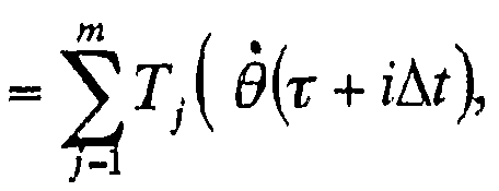
- the torque per blade of blade 10 (the force that the wind turbine tries to rotate by receiving the wind force, and the unit is [N ⁇ m]) is the wind turbine shaft rotation angular velocity [0 ], which is determined by the wind direction and wind speed (corresponding to the wind speed vector [V]) received by the blade 10 and the pitch angle of the blade 10, so that the wind turbine torque T at time ⁇ + i ⁇ t ( t) is the following formula
- This function T j ([ ⁇ ], V j, a j) is measured or simulated in advance so that it can be calculated by the controller 40 or the signal processing unit 300.
- step 403b optimization of the pitch angle for t seconds (step 403b) will be described. Since the wind turbine shaft rotation angular speed [ ⁇ ] is constant and the wind direction and wind speed (corresponding to the wind speed vector [V]) can be predicted t seconds after the blade 10 receives, use Equation (8). Thus, at time ⁇ + ⁇ , the optimal pitch angle ⁇ ′ (+ + ⁇ +) at which the maximum torque can be obtained can be calculated. Therefore, the optimal pitch angle ⁇ ; 'that can be predicted at time ⁇ is
- the controller 40 adjusts the pitch angle to the optimal angle ⁇ .
- a pitch angle control signal of + ⁇ 1: is transmitted to the pitch angle control drive device 60 (step 404b), and the pitch angle control drive device 60 receives this signal to change the pitch angle (step 4).
- the wind direction and wind speed at the current time ⁇ used in the calculation should be measured values (actual data) (Step 406 b).
- the pitch angle of all blades 10 is optimally controlled by repeating for each of the blades 10 of the three main blades. And, of course, and Wind data obtained from the laser-type wind anemometer (observations) in groups, which in other than techniques may predict controlling the pitch angle.
- the change in the wind speed is a perceived force. If the pitch angle is changed, the blade performance is significantly affected, and if the wind direction changes while the pitch angle is changed. Was adversely affected. Also, when measuring the wake after passing through the blade 10 above the nacelle 20 with a mechanical wind direction anemometer, the cycle is about 1 second from the blade 10 (varies according to the windmill speed). And the pitch angle could only be changed based on the average value for one second. Also, during actual control, there was a delay in the response of the machine, etc., so only passive control with a considerable delay was possible.
- the above-mentioned method enables active control of the yaw angle, pitch angle, etc., in consideration of the response delay of the machine, and the blade 10 continues to receive the wind almost at the optimum pitch angle. Can be. Therefore, wind energy can always be used with higher efficiency than conventional passive control. Conversely, it can also be used to suppress output by suppressing the generated torque. In this case, if the optimum pitch angle in Expression (10) is arbitrarily set so as to suppress the generated torque, the output can be easily suppressed. In this way, the wind power generator can be easily and accurately controlled.
- FIG. Figure 5 shows the change in wind actually received by the wind power generator with a thick solid line 501 (actual wind direction change).
- the wind direction and wind speed of the wind received by the wind power generator and the arrival time of the wind are predicted from the wind direction and wind speed data (observation results) obtained by the laser anemometer, and the propeller (Blade) Since the angle of rotation is controlled so as to match the plane of rotation, as can be seen from Fig.
- the optical system unit 2 0 0 of the laser type anemometer operates to continue to receive squarely the nacelle 2 0 and the monitor wind the value of the Doppler shift F D, larger values Therefore, there is an effect that the detection accuracy of the wind direction and the wind speed can be further improved.
- the optical system 200 of the laser anemometer has been described as being placed on the nacelle '20.
- a control drive device for rotating the system unit 200 may be provided, and the structure may be such that the drive unit is rotated not only by the rotation of the nacelle 20 but also by a dedicated control drive device. Further, it may be provided on a pole provided separately from the tower section 2 so as to be mounted on a control drive device similar to the yaw angle drive control device 50. Also, the example in which the main body 100 and the signal processing unit 300 are arranged in the tower unit 2 has been described, but with these arrangements, the communication state with other components is preferably maintained. If it can be done, there is no problem even if it is arranged outside the part 2 part.
- a wind power generation system including a wind power generator consists of a wind power generator consisting of blades 10, nacelles 20, generators 30, towers 2, etc., and a laser wind direction that detects wind coming toward the wind turbine in front of the wind turbine.
- An anemometer 100, 200, 300
- a control operation unit that predicts the power generation output based on the predicted values of the wind direction and wind speed calculated by the laser anemometer and determines the control amount (for example, It is also possible to use a controller equivalent to the controller 40 or a dedicated arithmetic unit separately provided and connected for use).
- an output smoothing unit installed to satisfy the control amount It is configured to include the device 80.
- the output smoothing device 80 is connected to the outside of the wind power generator, is a device for smoothing the output, and is connected to a power cable 82 connected to the generator 30 via the power converter 81. Have been. Further, as described above, the transformer 83 is disposed in the power cable 82 located between the power system 84 from which the generated power of the wind power generator is output and the power converter 81.
- the wind direction calculated based on the observation result of the laser wind anemometer is used.
- the wind energy is controlled by changing the direction of the wind turbine and pitch control by changing the angle of the blades, thereby controlling the input energy of the wind power and controlling the output of the wind power generation system.
- the measurement range of the laser-type anemometer requires a sufficient amount of time for system control, but a distance of about 20 Om is usually sufficient. That is, generally, the rated wind speed of a wind power generation system is 10 to 2 Om / 's, but if the wind direction wind speed of about 20 Om is known, it takes at least several seconds for the wind to reach the windmill. It takes up to several tens of seconds, and this time is sufficient as time for predictive control of the wind turbine.
- FIG. 6 shows a schematic diagram of the configuration of the variable-speed wind power generation system.
- This system includes a variable speed generator 800 instead of the generator 30 of the wind generator described above.
- the variable speed generator 800 and the power converter 810 are connected by a power cable 820.
- the power converter 810 is connected to the generator-side power converter 810a, DC capacitor 810, and system-side power converter 810b sequentially from the side near the variable-speed generator 800. It is arranged and configured.
- a transformer 83 is arranged between the power system 84 and the power converter 810, and an output smoothing device 80 is required between the transformer 83 and the power converter 810. Accordingly, they are connected via the power converter 81.
- the DC capacitor 811 controls the active power of the output of the variable speed generator 800.This active power flows from the generator-side power converter 8110a to the DC side. DC capacitor voltage rises. The difference between this DC capacitor 811 voltage and the DC voltage reference given in advance as a command value is amplified to obtain the active current command on the AC side (system power converter 8110b side), and the active current is Power is discharged to the grid by increasing control.
- the detailed configuration of the wind power generator is the same as that provided with the normal power generator 30, and a description thereof will be omitted.
- the variable-speed generator 800 its output is controlled by power converters (810a, 810b), and when a strong wind blows momentarily, the energy from the wind is once enabled.
- the rotational speed of the variable-speed generator 800 is stored in the form of mechanical energy as an increase in the rotational speed, and when the wind speed decreases, the rotational energy of the variable-speed generator 800 is converted into electrical energy, and the result is obtained.
- the feature is that the output of the wind power generation system can be smoothed. That is, output fluctuation suppression control of the wind power generation system can be performed.
- variable-speed wind power generation system for example, if the wind speed decreases for a long time (minutes), the rotation speed (rotation speed) decreases in the same way as above, and attempts to smooth the electrical output.
- the long-term decrease in output could not be sufficiently compensated, and the decrease in output power due to the decrease in wind speed could not be avoided.
- advance prediction control according to the present invention is used, a decrease in wind speed can be predicted in advance, the decrease in output power can be reduced, and the output can be smoothed.
- the variable speed can be achieved by other methods, but any method may be used as long as variable speed power generation is possible.
- variable-speed type wind power generation system When the present invention is applied to this variable-speed type wind power generation system, the feature of smoothing electrical output can be implemented more effectively.
- the wind energy to be taken in the future when the wind energy to be taken in the future is large based on the prediction data, the wind power is systematically generated and the minimum rotation speed, that is, the energy is stored as mechanical energy Standby with the maximum capacity, or when wind energy to be taken in the future is weak, systematically convert rotational energy into electrical energy and release it to minimize the effect on the grid at that moment. It is possible to control the number of revolutions of the generator, and to control the frequency output and voltage fluctuation due to the power generation output of the wind power generation system within the specified range, and to smooth the generated output.
- Ku Wind Farm> Ku Wind Farm>
- Fig. 7 is a block diagram of a wind farm in which a plurality of wind power generators 610a to 610c are installed.
- the optical system section of the laser wind anemometer is located near the center of the wind farm.
- a tower unit (pole) 601 is set up near the center, and the optical system unit 200 is placed on the tower unit 601 via a single-angle control drive unit (hereinafter, drive unit) 602 for the optical system unit.
- the optical system section 200 is connected to the main body section 100 and the optical fiber 130a, the main body section 100 and the signal processing section 300 are connected to the communication system section 131a, and the signal processing section 300 and each wind power generator.
- Controllers 40a to 40c are connected by communication system sections 132a to 132c.
- the signal processing unit 300 and the driving device 602 are connected by a communication system unit 602a.
- Controllers 40a to 40c are connected to wind power generators 6100a to 6100c by communication units 70a to 70c, respectively.
- the drive unit 602 changes the direction of the optical system unit 200 based on the output from the signal processing unit 300, and always faces the front of the wind or rotates at a constant speed.
- This is a drive device that can measure wind direction and wind speed in the circumferential direction.
- the optical system 200 is mounted on another pole in the above-mentioned single wind power generator.
- the optical system unit 200 and the driving device 602 may be installed on the ground.
- the laser-type anemometer uses the condensing point as X [m] (for example, 40 Om ahead) of the wind generator farthest from the tower section 601 (corresponding to 6100a in Fig. 7).
- the signal processing unit 300 includes a calculation function used for single-angle control for the optical system unit and, when a variable speed wind power generator is used, an output control for the variable speed wind generator. It has a calculation function and a calculation function for controlling the angle and pitch angle of each wind generator.
- the laser anemometer measures the wind direction at X [m] at the current time ⁇ (step 701).
- step 71 1 the wind direction and wind speed after t seconds received by the optical system unit 200 are calculated, and the optical system unit 200 is calculated so that the optical system unit 200 becomes the optimum angle after t seconds (step 71).
- step 7 1 2) using the calculated control signal to drive 6
- Step 7 13 drive 602 changes (Step 7 14).
- the calculation procedure is the same as the method described above (see the explanation in Fig. 4). However, when measuring the wind conditions around the entire circumference using a drive device that can measure the wind direction and wind speed over the entire circumference by rotating the optical system section 200 at a constant speed, It is not necessary to perform the first control operation of the optical system unit 200.
- a storage device (not shown) incorporated in the signal processing unit 300 stores the position from the laser type wind direction anemometer, that is, the optical system unit 200 to each of the wind power generators 61 0a to 61 0c. Based on this data, the wind direction and speed of the wind that will be received after ta seconds are calculated based on this data (step 721a).
- the wind turbine rotation speed is optimized (Step 7 22 a), and the calculated single-angle control signal, pitch angle control signal and variable-speed generator for ⁇ ta seconds (output) are output.
- the control signal is transmitted to the controller 40a of the wind power generator 6100a (step 7223a).
- the controller 40a of the wind power generator 610a transmits a control signal to the single angle control drive, pitch angle control drive, and inverter of the wind power generator 610a,
- the angle control drive changes the angle
- the pitch angle control drive changes the pitch angle
- the inverter changes the output (step 724a).
- Operation 2b, 2c steps 7 21a to 724c) similar to operation 2a of wind generator 610a, and operation of wind generator 610b, 610c simultaneously Do.
- the wind direction and wind speed cannot be measured in an optimal state.
- each of the wind generators 610a to 610c can use the wind energy with high efficiency.
- the signal processing unit 300 is equipped with a calculation function for the angle control of the optical system and a calculation mechanism for the angle, pitch angle and output control of each wind power generator.
- a computer with this calculation function was separately connected to the optical system section 200, a computer section was installed on each of the wind power generators 6100a to 6100c, It is also possible to configure the computer 40 to have this calculation function.
- the output adjustment amount of the wind power generator is preliminarily determined from the wind condition prediction data obtained by the laser wind direction anemometer, and the surplus power is stored in the output smoothing device based on the calculation condition, or If the generated power is insufficient, the stored energy is released, and the output smoothing device is operated to suppress the fluctuation to a level that the existing power generation system of the system can follow, and the entire system is generated Performs power stabilization (smoothing).
- Examples of output smoothing devices combined with wind power generators include lead-acid batteries, NAS batteries, redox flow batteries, electric double-layer capacitors, and reactive power compensators (Static
- the output smoothing device controls the output so that the output fluctuation of the wind power generation system is canceled when the wind observed by the laser anemometer reaches the wind power generator.
- the Storage battery A because i 0 in those constituted mainly by the large DC battery rectifier
- the reactive power compensator is used to prevent voltage fluctuations and flicker (prevent flicker) in the power system when connecting the wind power generation system to the power system.
- flicker prevent flicker
- the output of the wind power generator causes voltage fluctuations in the system, causing abnormal stoppage or malfunction of other equipment, flickering of lighting equipment, etc.
- a reactive power compensator is required as a countermeasure.
- Output limiting resistance limits and suppresses fluctuations in wind power generator output due to wind speed fluctuations. If the wind power generator output due to wind speed fluctuations exceeds a certain value, the excess is consumed as heat by a resistance device. This is to limit the output and allow the power within the specified value to flow out to the grid.
- the wind power generation preliminary wind condition prediction output control device (to be referred to as a device for determining various control amounts based on data obtained by a laser-type anemometer) and output smoothing described above.
- the output smoothing of a wind power generation system using a combination of the optimization device 80 will be described with reference to FIG.
- the generator 30 provided in the wind power generator and the power system 84 are connected by a power cable 82, and the power cable 82 is connected via a power converter 81.
- Output smoothing device 80 is connected.
- a transformer 83 is arranged between the power converter 81 and the power system 84.
- the output fluctuation smoothing system (the system including the above-mentioned wind power generation preliminary wind condition prediction output control device, the power converter 81 and the output smoothing device 80) is designed to predict the wind conditions and predict the wind power output. Predict and control the amount of power input and output of the output smoothing device 80 to suppress fluctuations in the output of the wind power system as a whole, or to easily achieve complete smoothing. This enables stable supply of electric power using a wind power generator.
- the wind direction and wind speed in front of the wind generator (e.g., 400 m) can be determined with high precision and high resolution, even in combination with a wind generator that can control the pitch angle and angle, or a wind generator that does not.
- the wind direction and wind speed that the wind power generator will receive after a certain period of time (for example, after 40 seconds) is estimated, and the output smoothing device 80
- the system is designed to optimize the power input and output of the wind turbine in a direction to cancel the increase and decrease of the output generated by the wind generator.
- the output power of the wind power generator can be completely smoothed. This allows the wind power generators to be connected without affecting the power system 84 at all.
- the average value of the wind power output during a certain period is the combined output target value of the wind generator and the output smoothing device 80. If the wind power output is larger than the combined output target value, the difference is calculated. The storage battery or the like is charged. On the other hand, when the wind power output is smaller than the combined output target value, the difference is discharged from the storage battery or the like.
- the maximum charge power and the maximum discharge power are determined to be constant values as shown in Fig. 11, and the limit values of the charge and discharge are indicated by broken lines, respectively. By performing charging and discharging, it is possible to achieve the combined output target value.
- the output of a wind power generator is predicted, and it is possible to smooth even a very small power fluctuation that cannot be smoothed to a condition that satisfies a target value of the generated output by the conventional method.
- the state of the smoothing is, for example, as shown in (c) of FIG.
- the output smoothing device 80 in addition to the original output smoothing device, the output smoothing function of the load may be positively used.
- FIG. 12 shows an example of a control block diagram of the wind power generation system.
- FIGS. 13 and 14 will be used to describe an operation flow in the case where the wind power generator and the output smoothing device 80 are combined, using the wind power generation system in the wind farm shown in FIG. 7 as an example. Note that G and ⁇ in FIG. 13 are connected to G and ⁇ in FIG.
- FIG. 13 and FIG. 14 represent one flow diagram.
- the operations from step 70 1 to step 72 4 a in FIGS. 13 and 14 (including operation 1 and operations 2 a to 2 c) have been described in the second embodiment, and a description thereof will be omitted. I do.
- the output smoothing device 80 performs the operation 3 from step 931 to step 934 in FIG.
- the signal processor 300 stores the position from the laser anemometer to each wind power generator in a vector, and based on the measurement results of the laser anemometer and this position data, Calculate the wind direction and wind speed that the wind generator will receive after t seconds (step 931).
- the signal processor 300 calculates the amount of wind power generation in t seconds in the near future based on the wind direction and wind speed received by each wind power generator in the near future, and uses this to calculate the output smoothing device in t seconds.
- the power input / output amount at 80 is optimized (step 932). The optimization method is the same as that described above.
- the output of the wind generator at this time is the sum of the power generated by all the wind generators.
- the signal processing unit 300 sends a control signal to the power conversion device 81 so that the actual power input / output of the output smoothing device 80 becomes the calculated optimum value (step 933).
- the power conversion device 81 inputs and outputs the power of the output smoothing device 80.
- the fluctuation of the grid power due to the power generated by the wind power generator is suppressed (step 934).
- Embodiment 1 Another power generation means include, for example, diesel power generation, storage batteries, solar power generation, and variable speed pumps. Further, by combining a load with the hybrid power generation system, the output can be smoothed more efficiently.
- Fig. 15 conceptually shows the difference in the amount of power generated when a laser-type anemometer is not installed and when it is installed.
- Fig. 15 (a) shows the relationship between the change in wind direction and the direction of the windmill
- Fig. 15 (b) shows the time chart.
- the direction of the nacelle 20 can quickly follow the wind direction in response to the change in the wind direction, as described with reference to Fig. 5. .
- time t. Ma The windmill is facing directly in front of the wind direction during
- the system will be shared with service subscribers who have leased the system (eg, wind power generation system owners and operators). • Pitch angle control
- Figure 16 shows the output power characteristics of each wind generator with respect to the wind speed (referred to as a wind turbine performance curve), and is prepared for each wind generator.
- the pitch angle is fixed in the wind speed range below the rated output (below the rated wind speed shown in Fig. 16). This portion is shown as F 1 in FIG.
- the portion of F2 is a pitch variable region.
- the lift coefficient is the angle difference between the pitch angle of the blade 10 and the angle between the relative speed U of the rotor speed Vr and the wind speed Vn and the angle of the chord line as shown in Fig. 17 (b). And the angle ( ⁇ ).
- the rotor speed Vr is the rotation speed of the rotating shaft 12.
- the lift coefficient CL has a blade stall area C, so conventionally, the lift coefficient CL was operated in the operation area A with a margin from the maximum value of the lift coefficient.
- the output of the wind power generation system can be increased by shifting the operation range to the operation range B closer to the stall range C and increasing the lift coefficient.
- the effect of the output gap appears in the direction indicated by the arrow D in Fig. 17 (a) on the wind turbine characteristics as an improvement in the lift coefficient.
- Fig. 18 shows a wind power generator of a wind power generation system according to the present invention, which has a portion for performing comparative evaluation of generated power depending on the presence or absence of a laser-type anemometer.
- a wind power output calculation unit 400a that performs comparative evaluation of the generated power with and without a laser anemometer, and a cup type installed on the conventional nacelle 20 Wind direction A total of 500 is provided.
- Input information 401 to wind power generation output calculation unit 400a is wind direction and wind speed data by laser anemometer, start time of single angle control by laser anemometer, wind speed by laser anemometer The pitch angle change amount based on the measured value is input.
- wind direction and wind speed data from a cup-type wind direction anemometer 500 are input.
- the start time of the one-angle control by the cup-type wind direction anemometer 500 and the pitch angle change amount based on the wind speed measurement value by the cup-type wind direction anemometer 500 are determined by the input information 501 and the wind power generation output calculation unit 4. It is determined within 0 0 a.
- the pitch angle is operated below the rated speed.
- the difference in the amount of generated power depending on the presence or absence of the laser anemometer is determined as follows. For example, the wind power generation output calculation unit 400a of FIG.
- wind turbine 18 configured by a computer, a memory, and the like has a wind turbine characteristic represented by wind speed versus output power as shown in FIG. 16 as a function of a memory (not shown). Is stored in The evaluation of wind turbine output is based on the time immediately after the start of operation, and shall be implemented over time thereafter. In this evaluation, the direction of the nacelle and the pitch angle are different depending on whether the laser anemometer is installed or not. For this reason, the output generated without a laser-type anemometer immediately after the start of operation (base time ij) is evaluated by simulation. In other words, in the evaluation of the cup-type anemometer 5 ⁇ 0, the virtual windmill movement based on the data of the cup-type anemometer was set as the movement of the windmill after the reference time, and the output was output. Simulate.
- the direction of the wind turbine that would move based on the same data was determined by simulation, and the total wind speed for that direction was calculated.
- the vector component is obtained, and this is used as the wind speed when virtually obtaining the output of the wind turbine.
- the wind turbine characteristics shown in Fig. 16 are used to evaluate the laser anemometer in the same way as the cup anemometer. That is, the wind speed obtained as measured data is given to the horizontal axis in Fig. 16, and the output power is read from the vertical axis in Fig. 16 and evaluated.
- the pitch angle must be given as a parameter when the wind speed is lower than the rated wind speed.However, if a function of the wind turbine characteristic corresponding to each pitch angle is prepared, it is sufficient. ,.
- the above evaluation of the output power is continued until the wind turbine stops, and if the difference in the output power is determined, it can be obtained as a comparison of the power with and without the laser anemometer. If the difference between the simulation and the actual output power cannot be ignored, the simulation results may be corrected to match the actual operation output. Furthermore, it is advisable to conduct evaluations by summing up evaluations that have been performed for a predetermined period (one day, one week, one month, one year).
- the wind power generation output calculation unit 400a in FIG. 18 has an algorithm for performing the above-described calculation evaluation.
- the evaluation of the added value associated with the environmental improvement by, for example, the CO 2 reduction effect by predictive control of a wind power generator using a laser wind direction anemometer is described in the wind power output calculation section 400 a in FIG. obtained in the difference between the output power amount with and without installed a laser type anemometer, for example wind power output computing part the amount of CO 2 diesel generators occurs when supplemented with diesel generators It is obtained by the added value calculation unit 400b connected to 400a.
- the value-added calculation unit 400b includes a table showing the relationship between the output power of the diesel generator and the amount of CO 2 generated at that time, and a table showing the relationship between the amount of CO 2 generated and the index indicating the effect of this on the environment ( both built not shown) in the memory, from which the amount of generated C_ ⁇ 2, further obtains the index indicating the environmental impact.
- the wind power output calculation unit 400 a and the value added calculation unit 400 b may be configured as one evaluation calculation unit 400.
- the evaluation calculation unit 400 is connected to a network N such as the Internet, and the service provider and the service subscriber can use the respective network terminals T l and T 2 to obtain the calculated evaluation information of the evaluation calculation unit 400. You may make it available. in this case, The evaluation operation unit 400 becomes one node (terminal) of the network. In addition, on the network N, a part of the service subscriber's profit based on the evaluation information from the service provider to the service provider via the terminal BT of the financial institution (the percentage contracted in advance) is automatically It may be transferred. In this case, the evaluation calculation unit 400 further sets the unit price of revenue (profit per unit) for each piece of evaluation information (increase in power sales and environmental impact index) and the dividend ratio of the service provider to the revenue in advance. Then, the total revenue is calculated based on these, the dividend to the service provider is calculated for this total revenue, and the automatic transfer procedure is performed via the terminal BT of the financial institution.
- Embodiment 2 Embodiment 2
- FIG. 19 shows a schematic configuration of a wind power generation system having another configuration according to the present invention.
- a resistor or a power absorbing device 90 is connected to a system side output terminal of the wind power generation system via a power converting device 81.
- the power converter 81 is provided with a wind direction and anemometer signal processing unit 300 of a wind power generator indicated by a generator 30 and a blade 10 ⁇ A controller 40 and a power meter 100 5 provided on a power cable 82.
- the power system 84 is connected to a power company via a load facility 1003 and a precision wattmeter 1001 via a transformer 83a.
- the resistor (or power absorbing device) 90 can release the power energy that exceeds the range that the system side accepts to the atmosphere as heat, or reduce it to some extent in order to suppress output fluctuations within the range allowed by the power system. Has the role of storing as energy.
- FIG. (A) of FIG. 20 shows the temporal change of the wind speed
- (b) of FIG. 20 shows the power generation output without the predictive control corresponding to the wind speed shown in (a) of FIG.
- the output of the curve as shown in Fig. 20 (b) as it is may adversely affect the system it is necessary to assume a marginal output limit range.
- Fig. 20 (b) In the portion indicated by G in ()), the output is suppressed by limiting the output of the windmill or consuming heat using a load such as a resistor 90, or temporarily storing energy by some means. As a result, The output suppression part is inevitably large.
- the part that is supposed to be over without control can be predicted as a specific output scale in advance, and the system can be tolerated. Judgment as to whether or not the change can be suppressed within a range that the system can tolerate can be performed by the feedforward, and the output limiting or suppressing portion can be limited to a smaller range.
- the improved part, whose output limitation and suppression have been released and can be used as output by prediction, is shown in Fig. 20 (c).
- G2 Shown as G2.
- the output limitation and suppression part G1 is also shown in the figure, the range is smaller than the part G in (b) of FIG.
- the part G2 that could not be used in the past can be used effectively, and the benefits (for example, increased profit) of this increase can be shared between the service provider and the service subscriber .
- a single laser-type anemometer consisting of the main body 100, the optical system 200, and the signal processor 300 is shared by multiple wind power generators 610a to 610c.
- a single laser-type anemometer consisting of the main body 100, the optical system 200, and the signal processor 300 is shared by multiple wind power generators 610a to 610c.
- Each of the wind power generators 6100a to 6100c is provided with the above-described evaluation calculation section 400. Furthermore, each evaluation operation unit 4
- the service provider and a plurality of service subscribers use the evaluation information calculated by each evaluation operation unit 400 from the network terminals T1 to T4. You may be able to.
- the evaluation operation unit 400 becomes one node (terminal) of the network.
- a portion of the service subscriber's increase in revenue based on the evaluation information is automatically transferred from the service subscriber to the service provider via the terminal ⁇ of the financial institution over the network ⁇ You may be able to.
- each evaluation calculation unit 400 further stores in advance the unit price of revenue (revenue per predetermined unit) for each piece of evaluation information (increase in power sales, environmental impact index), and the dividend ratio of the service provider to the revenue. Then, based on these, the total revenue is calculated, and a dividend is paid to the service provider for the total revenue, and the automatic transfer procedure is performed via the terminal ⁇ of the financial institution.
- a laser wind direction anemometer may be provided for each wind power generator as shown in FIG. 1S.
- Figure 22 shows the configuration when the present invention is applied to a hybrid power generation system in a weak system such as an isolated island.
- the wind power generators 61a to 61e, diesel generators (DG) 89a and 89b, and large-capacity storage batteries 80a are shown in Fig. 22 as examples of the power system network SN.
- the combination system of the storage battery 80 and the load 1003 is shown.
- Each of the wind power generators 610a to 610e is provided with an evaluation operation unit 400, and these evaluation operation units 400 are connected to the network N as shown in FIG. FIG. 22 omits the network N composed of the Internet and the like.
- the evaluation calculation section 400 may be connected to a network by communication.
- the data from the laser anemometers (100, 200, 300) may also be sent by communication.
- the output fluctuation of the wind power generation system in a relatively long period is predicted by a laser anemometer (the predicted amount is assumed to be A), and the level allowed by the system (B and The output of the diesel generator is controlled so that the output fluctuations become smooth (the output amount is B—A), and finally the output of the wind power generation system and the power smoothed output (B—A) With the system conditions
- the output waveform should be smooth.
- any device that has a power storage and discharge function such as a NAS battery, a redox flow battery, a flywheel, an electric double layer capacitor, and the like can be used in addition to ordinary storage batteries for beard-like fluctuations It is.
- FIG. 24 shows an example.
- the same or corresponding parts as those in FIG. 19 are denoted by the same reference numerals, and description thereof will be omitted.
- FIG. 24 shows a general configuration in which an output smoothing device 80 including a large-capacity storage battery, a flywheel, and the like is installed at the output end of the wind power generation system.
- the output smoothing device 80 is not always installed at the output end of the wind power generation system, but may be installed in a system.
- the predicted amount of generated power is calculated by the power controller 900 based on the data of the laser anemometer.
- the algorithm of the predicted amount calculation means in the power controller 900 is as shown in FIG. Prepare the response of the power smoothing device 80 so that the fluctuations in the forecast are within the range allowed by the grid, and optimize the operation (smoothing in accordance with the predicted fluctuation in the amount of wind power generation).
- the power is stored and discharged from the power supply).
- the wind direction and wind speed in a wind power generator are predicted in advance by observing the wind condition using a laser-type wind anemometer, and high-efficiency operation and output in a wind power generation system based on yaw control and pitch control are performed. It can also evaluate benefits such as the increase in power sales obtained by stabilization and the effect on the environment to be improved, so that it can be applied to various power systems, and wind condition observation using this laser-type anemometer It can be established as a business to provide these services.
Landscapes
- Engineering & Computer Science (AREA)
- Life Sciences & Earth Sciences (AREA)
- Sustainable Development (AREA)
- Sustainable Energy (AREA)
- Chemical & Material Sciences (AREA)
- Combustion & Propulsion (AREA)
- Mechanical Engineering (AREA)
- General Engineering & Computer Science (AREA)
- Wind Motors (AREA)
- Control Of Eletrric Generators (AREA)
Description


Claims
Priority Applications (4)
| Application Number | Priority Date | Filing Date | Title |
|---|---|---|---|
| EP04731728A EP1744058A1 (en) | 2004-05-07 | 2004-05-07 | Wind power generation evaluation system and prediction control service system for wind power generator |
| JP2006519149A JPWO2005108784A1 (ja) | 2004-05-07 | 2004-05-07 | 風力発電評価システム、風力発電機のための予測制御サービスシステム |
| US10/554,738 US20070035135A1 (en) | 2004-05-07 | 2004-05-07 | Wind power generation evaluation system and predictive control service system for use with wind power generator |
| PCT/JP2004/006499 WO2005108784A1 (ja) | 2004-05-07 | 2004-05-07 | 風力発電評価システム、風力発電機のための予測制御サービスシステム |
Applications Claiming Priority (1)
| Application Number | Priority Date | Filing Date | Title |
|---|---|---|---|
| PCT/JP2004/006499 WO2005108784A1 (ja) | 2004-05-07 | 2004-05-07 | 風力発電評価システム、風力発電機のための予測制御サービスシステム |
Publications (1)
| Publication Number | Publication Date |
|---|---|
| WO2005108784A1 true WO2005108784A1 (ja) | 2005-11-17 |
Family
ID=35320281
Family Applications (1)
| Application Number | Title | Priority Date | Filing Date |
|---|---|---|---|
| PCT/JP2004/006499 WO2005108784A1 (ja) | 2004-05-07 | 2004-05-07 | 風力発電評価システム、風力発電機のための予測制御サービスシステム |
Country Status (4)
| Country | Link |
|---|---|
| US (1) | US20070035135A1 (ja) |
| EP (1) | EP1744058A1 (ja) |
| JP (1) | JPWO2005108784A1 (ja) |
| WO (1) | WO2005108784A1 (ja) |
Cited By (7)
| Publication number | Priority date | Publication date | Assignee | Title |
|---|---|---|---|---|
| WO2008126659A1 (ja) * | 2007-04-10 | 2008-10-23 | Mitsubishi Heavy Industries, Ltd. | 風力発電装置及びその制御方法 |
| CN101978161A (zh) * | 2008-10-29 | 2011-02-16 | 三菱重工业株式会社 | 风力发电装置及其控制方法 |
| JP4782245B1 (ja) * | 2010-06-16 | 2011-09-28 | 三菱重工業株式会社 | 風力発電装置の制御装置及び制御方法 |
| KR101079763B1 (ko) | 2009-03-03 | 2011-11-04 | 경상대학교산학협력단 | 풍력발전기의 비용 기여도 산출방법, 이에 적용되는 비용 기여도 산출장치 및 기록매체 |
| JP2013177885A (ja) * | 2012-02-02 | 2013-09-09 | Mitsubishi Heavy Ind Ltd | 風力発電装置及びその運転制御方法 |
| KR101466099B1 (ko) * | 2013-10-18 | 2014-11-27 | 삼성중공업 주식회사 | 풍력발전단지 운영 시스템 및 그 방법 |
| KR101506955B1 (ko) * | 2013-10-14 | 2015-03-30 | 동명대학교산학협력단 | 권선저항을 이용한 소형 풍력발전시스템용 전원제어장치 |
Families Citing this family (66)
| Publication number | Priority date | Publication date | Assignee | Title |
|---|---|---|---|---|
| US8277964B2 (en) | 2004-01-15 | 2012-10-02 | Jd Holding Inc. | System and method for optimizing efficiency and power output from a vanadium redox battery energy storage system |
| EP1571746B1 (en) * | 2004-03-05 | 2018-09-12 | Gamesa Innovation & Technology, S.L. | Active power regulating system of a wind farm |
| US7227275B2 (en) * | 2005-02-01 | 2007-06-05 | Vrb Power Systems Inc. | Method for retrofitting wind turbine farms |
| US7282807B2 (en) * | 2005-12-20 | 2007-10-16 | General Electric Company | Systems and methods for testing a wind turbine |
| US7560823B2 (en) * | 2006-06-30 | 2009-07-14 | General Electric Company | Wind energy system and method of operation thereof |
| US7642666B2 (en) * | 2006-11-02 | 2010-01-05 | Hitachi, Ltd. | Wind power generation apparatus, wind power generation system and power system control apparatus |
| CN100460669C (zh) * | 2007-02-08 | 2009-02-11 | 上海交通大学 | 基于风向标和输出功率的风力机偏航控制方法 |
| ES2656542T3 (es) * | 2007-08-31 | 2018-02-27 | Vestas Wind Systems A/S | Método para el control de al menos un mecanismo de regulación de una turbina eólica, una turbina eólica y un parque eólico |
| US8987939B2 (en) | 2007-11-30 | 2015-03-24 | Caterpillar Inc. | Hybrid power system with variable speed genset |
| US7944184B2 (en) * | 2008-04-07 | 2011-05-17 | Korea Electric Power Corporation | Static compensator apparatus for HVDC system |
| DK2110551T4 (da) * | 2008-04-15 | 2019-05-13 | Siemens Ag | Fremgangsmåde og indretning til prognose-baseret vindmøllestyring |
| EP2133560A1 (en) * | 2008-06-11 | 2009-12-16 | Flexenclosure AB | Wind turbine and power supply system |
| EP2313652B1 (en) * | 2008-06-30 | 2016-07-27 | Vestas Wind Systems A/S | A method of controlling a wind power plant |
| US8785023B2 (en) * | 2008-07-07 | 2014-07-22 | Enervault Corparation | Cascade redox flow battery systems |
| US7820321B2 (en) * | 2008-07-07 | 2010-10-26 | Enervault Corporation | Redox flow battery system for distributed energy storage |
| FR2940437B1 (fr) * | 2008-12-22 | 2013-02-15 | Airbus France | Outil, ensemble d'outillages et procede de reglage du pas des pales d'une helice de maquette |
| CN102265477B (zh) * | 2008-12-26 | 2014-01-08 | 日本风力开发株式会社 | 并设蓄电池式的风力发电系统和蓄电池的充放电控制装置 |
| JP4995209B2 (ja) * | 2009-01-05 | 2012-08-08 | 三菱重工業株式会社 | 風力発電装置及び風力発電装置の風向推定方法 |
| EP2213875A1 (en) * | 2009-01-30 | 2010-08-04 | Siemens Aktiengesellschaft | Method and arrangement to forecast an output-power of at least one wind-turbine |
| US8178986B2 (en) | 2009-03-18 | 2012-05-15 | General Electric Company | Wind turbine operation system and method |
| JP5430994B2 (ja) * | 2009-03-27 | 2014-03-05 | 株式会社日本総合研究所 | 充放電制御装置、及び充放電制御方法 |
| US7941304B2 (en) * | 2009-04-30 | 2011-05-10 | General Electric Company | Method for enhancement of a wind plant layout with multiple wind turbines |
| US8441138B2 (en) * | 2009-05-07 | 2013-05-14 | Vestas Wind Systems A/S | Wind turbine |
| US20100283246A1 (en) * | 2009-05-07 | 2010-11-11 | Vestas Wind Systems A/S | Wind turbine |
| WO2010131305A1 (ja) * | 2009-05-15 | 2010-11-18 | パナソニック株式会社 | 電力線通信装置、及び電力線通信システム |
| JP2012532583A (ja) * | 2009-06-29 | 2012-12-13 | パワージェティクス, インコーポレイテッド | 可変発電機を用いた電力負荷低減のための高速フィードバック |
| CA2771724A1 (en) * | 2009-08-21 | 2011-02-24 | Catch the Wind, Inc. | Wind and power forecasting using lidar distance wind sensor |
| JP5606114B2 (ja) * | 2010-03-19 | 2014-10-15 | 株式会社東芝 | 発電量予測装置、予測方法及び予測プログラム |
| DE102010016292A1 (de) | 2010-04-01 | 2011-10-06 | Ssb Wind Systems Gmbh & Co. Kg | Kontrolleinrichtung für eine Windkraftanlage |
| GB2481789A (en) * | 2010-06-30 | 2012-01-11 | Vestas Wind Sys As | Reducing yaw error in wind turbines |
| JP5386444B2 (ja) * | 2010-06-30 | 2014-01-15 | 株式会社日立製作所 | 蓄電池制御装置及び蓄電池の制御方法、及び蓄電池の仕様決定方法 |
| US20120001428A1 (en) * | 2010-07-02 | 2012-01-05 | Calhoon Scott W | Wind energy system |
| US8709629B2 (en) | 2010-12-22 | 2014-04-29 | Jd Holding Inc. | Systems and methods for redox flow battery scalable modular reactant storage |
| CN103477070A (zh) * | 2011-02-11 | 2013-12-25 | 赛泽利斯公司 | 控制风力涡轮机包括控制偏转或其它参数的系统和方法 |
| US8980484B2 (en) | 2011-03-29 | 2015-03-17 | Enervault Corporation | Monitoring electrolyte concentrations in redox flow battery systems |
| US8916281B2 (en) | 2011-03-29 | 2014-12-23 | Enervault Corporation | Rebalancing electrolytes in redox flow battery systems |
| US10141594B2 (en) | 2011-10-07 | 2018-11-27 | Vrb Energy Inc. | Systems and methods for assembling redox flow battery reactor cells |
| US9853454B2 (en) | 2011-12-20 | 2017-12-26 | Jd Holding Inc. | Vanadium redox battery energy storage system |
| CN102797629B (zh) * | 2012-08-03 | 2014-05-14 | 国电联合动力技术有限公司 | 一种风电机组的控制方法、控制器及其控制系统 |
| CN102880810B (zh) * | 2012-10-25 | 2015-07-15 | 山东电力集团公司电力科学研究院 | 基于时间序列和神经网络法的风电功率预测方法 |
| US20140312620A1 (en) * | 2013-04-17 | 2014-10-23 | General Electric Company | Method and apparatus for improving grid stability in a wind farm |
| CN103473438B (zh) * | 2013-08-15 | 2018-07-31 | 国家电网公司 | 风功率预测模型优选及修正方法 |
| CN103455716B (zh) * | 2013-08-23 | 2018-08-31 | 国家电网公司 | 一种基于超短期风电功率预测的电力系统电压稳定裕度计算方法 |
| ES2879915T3 (es) * | 2013-11-29 | 2021-11-23 | Ge Renewable Tech Wind Bv | Procedimientos para operar una turbina eólica, y turbinas eólicas |
| CN103927695B (zh) * | 2014-04-22 | 2017-11-24 | 国家电网公司 | 基于自学习复合数据源的风电功率超短期预测方法 |
| KR20150130154A (ko) * | 2014-05-13 | 2015-11-23 | 엘에스산전 주식회사 | 고전압 직류 송전 시스템 제어 장치 |
| DE102014223853A1 (de) * | 2014-11-24 | 2016-05-25 | Siemens Aktiengesellschaft | Verwendung eines LIDAR-Systems zurKurzzeitvorhersage erwarteter Windverhältnisse und alsBasis für ein Kraftwerksmanagement sowieKraftwerksmanagementverfahren auf Basis eines voneinem LIDAR-System erhältlichen und erwarteteWindverhältnisse kodierenden Signals |
| JP6847343B2 (ja) * | 2015-02-23 | 2021-03-24 | 学校法人沖縄科学技術大学院大学学園 | 再生可能エネルギーの変動に対する予測誤差を決定するシステムおよび方法 |
| US11181096B2 (en) | 2015-12-23 | 2021-11-23 | Vestas Wind Systems A/S | Control method for a wind turbine |
| EP3394434B1 (en) | 2015-12-23 | 2022-05-04 | Vestas Wind Systems A/S | Control method for a wind turbine |
| CN105626391A (zh) * | 2016-03-04 | 2016-06-01 | 云南电网有限责任公司电力科学研究院 | 一种基于激光测风雷达的风电单台机组功率曲线测试方法 |
| AT15428U1 (de) | 2016-03-16 | 2017-08-15 | Uptime Holding Gmbh | Verfahren zur Bestimmung der Windgeschwindigkeit sowie Anlage zur Durchführung desselben |
| JP6933450B2 (ja) * | 2016-06-20 | 2021-09-08 | 株式会社日立製作所 | 電圧無効電力監視制御装置及び方法 |
| CN106894950B (zh) * | 2017-03-09 | 2019-02-12 | 华电电力科学研究院 | 一种基于风电机组传动特性的功率特性验证方法 |
| EP3604799A4 (en) * | 2017-04-26 | 2020-04-15 | Mitsubishi Electric Corporation | AI DEVICE, LASER RADAR DEVICE, AND WIND FARM CONTROL SYSTEM |
| US10451039B2 (en) * | 2017-06-09 | 2019-10-22 | General Electric Company | System and method for reducing wind turbine noise during high wind speed conditions |
| CN110206685B (zh) * | 2018-02-28 | 2020-07-28 | 北京金风科创风电设备有限公司 | 风电场中的风力发电机组的前馈控制方法和设备 |
| US11243331B2 (en) * | 2018-11-09 | 2022-02-08 | Itron, Inc. | Techniques for geolocation and cloud detection with voltage data from solar homes |
| CN110968942A (zh) * | 2019-11-11 | 2020-04-07 | 许昌许继风电科技有限公司 | 一种基于周边环境的风电机组的性能评估方法 |
| RU2765158C2 (ru) * | 2020-02-10 | 2022-01-26 | Владимир Иванович Чиндяскин | Ветродизельная электростанция |
| CN114263565B (zh) * | 2020-09-16 | 2024-04-12 | 金风科技股份有限公司 | 风力发电机组的偏航控制设备及方法 |
| CN112943532B (zh) * | 2021-03-04 | 2023-12-19 | 中国大唐集团科学技术研究院有限公司华中电力试验研究院 | 一种风力发电机组变桨系统桨叶操作互锁方法及装置 |
| CN113991754B (zh) * | 2021-12-24 | 2022-03-18 | 中国电力科学研究院有限公司 | 一种风电场的控制方法、系统及计算设备 |
| CN116954169A (zh) * | 2023-07-19 | 2023-10-27 | 天津市易控科技发展有限公司 | 基于dcs控制的信息安全控制方法、装置、设备及介质 |
| CN116707035B (zh) * | 2023-08-07 | 2023-09-29 | 江苏蔚风能源科技有限公司 | 一种依赖低风速动态规划的有功功率控制方法 |
| CN117989054A (zh) * | 2024-04-03 | 2024-05-07 | 东方电气风电股份有限公司 | 一种国产化风机智能控制方法、系统和设备 |
Citations (6)
| Publication number | Priority date | Publication date | Assignee | Title |
|---|---|---|---|---|
| JPH0587823A (ja) * | 1991-03-29 | 1993-04-06 | Raytheon Co | 風向を検出する装置および方法 |
| JPH11159436A (ja) * | 1997-11-26 | 1999-06-15 | Hitachi Eng & Service Co Ltd | 風力発電システム |
| JP2000087841A (ja) * | 1998-09-09 | 2000-03-28 | Toshiba Corp | 風力発電システム |
| JP2002027679A (ja) * | 2000-07-10 | 2002-01-25 | Mitsubishi Heavy Ind Ltd | 風力発電制御方法及びその装置 |
| JP2002152975A (ja) * | 2000-11-10 | 2002-05-24 | Mitsubishi Heavy Ind Ltd | 風車発電システム |
| JP2003083229A (ja) * | 2001-09-06 | 2003-03-19 | Mitsubishi Heavy Ind Ltd | 風力発電制御装置およびその制御方法 |
Family Cites Families (17)
| Publication number | Priority date | Publication date | Assignee | Title |
|---|---|---|---|---|
| US3838924A (en) * | 1970-11-04 | 1974-10-01 | Singer General Precision | Vector velocimeter (direction indicating velocimeter) |
| US3820896A (en) * | 1973-01-02 | 1974-06-28 | Singer Co | Velocimeter with improved signal to noise ratio |
| US3897152A (en) * | 1974-02-04 | 1975-07-29 | Us Air Force | Laser doppler velocimeter |
| US3984685A (en) * | 1975-12-03 | 1976-10-05 | Nasa | Wind measurement system |
| US4647933A (en) * | 1984-10-31 | 1987-03-03 | The United States Of America As Represented By The Secretary Of Commerce | Phased antenna array for wind profiling applications |
| US4651017A (en) * | 1985-02-08 | 1987-03-17 | The United States Of America As Represented By The United States Department Of Energy | Wind energy conversion system |
| DE3520214C1 (de) * | 1985-06-05 | 1986-07-10 | Deutsche Forschungs- und Versuchsanstalt für Luft- und Raumfahrt e.V., 5300 Bonn | Messeinrichtung zur Bestimmung der Windrichtung und Windgeschwindigkeit in der Atmosphaere |
| US4652122A (en) * | 1985-06-26 | 1987-03-24 | United Technologies Corporation | Gust detection system |
| US5724125A (en) * | 1994-06-22 | 1998-03-03 | Ames; Lawrence L. | Determination of wind velocity using a non-vertical LIDAR scan |
| WO1998042980A1 (en) * | 1997-03-26 | 1998-10-01 | Forskningscenter Risø | A wind turbine with a wind velocity measurement system |
| JP3614751B2 (ja) * | 2000-03-21 | 2005-01-26 | 東京電力株式会社 | コンバインド発電プラントの熱効率診断方法および装置 |
| JP3465246B2 (ja) * | 2001-11-08 | 2003-11-10 | 学校法人東海大学 | 流体発電装置 |
| US7042109B2 (en) * | 2002-08-30 | 2006-05-09 | Gabrys Christopher W | Wind turbine |
| JP4102278B2 (ja) * | 2003-03-19 | 2008-06-18 | 三菱電機株式会社 | 風力発電システム |
| EP1666723A4 (en) * | 2003-09-10 | 2011-04-13 | Mitsubishi Heavy Ind Ltd | SHAFT MOUNTING ANGLE CONTROL UNIT AND WIND TURBINE GENERATOR |
| US7476985B2 (en) * | 2005-07-22 | 2009-01-13 | Gamesa Innovation & Technology, S.L. | Method of operating a wind turbine |
| US20070124025A1 (en) * | 2005-11-29 | 2007-05-31 | General Electric Company | Windpark turbine control system and method for wind condition estimation and performance optimization |
-
2004
- 2004-05-07 JP JP2006519149A patent/JPWO2005108784A1/ja active Pending
- 2004-05-07 EP EP04731728A patent/EP1744058A1/en not_active Withdrawn
- 2004-05-07 US US10/554,738 patent/US20070035135A1/en not_active Abandoned
- 2004-05-07 WO PCT/JP2004/006499 patent/WO2005108784A1/ja not_active Application Discontinuation
Patent Citations (6)
| Publication number | Priority date | Publication date | Assignee | Title |
|---|---|---|---|---|
| JPH0587823A (ja) * | 1991-03-29 | 1993-04-06 | Raytheon Co | 風向を検出する装置および方法 |
| JPH11159436A (ja) * | 1997-11-26 | 1999-06-15 | Hitachi Eng & Service Co Ltd | 風力発電システム |
| JP2000087841A (ja) * | 1998-09-09 | 2000-03-28 | Toshiba Corp | 風力発電システム |
| JP2002027679A (ja) * | 2000-07-10 | 2002-01-25 | Mitsubishi Heavy Ind Ltd | 風力発電制御方法及びその装置 |
| JP2002152975A (ja) * | 2000-11-10 | 2002-05-24 | Mitsubishi Heavy Ind Ltd | 風車発電システム |
| JP2003083229A (ja) * | 2001-09-06 | 2003-03-19 | Mitsubishi Heavy Ind Ltd | 風力発電制御装置およびその制御方法 |
Cited By (14)
| Publication number | Priority date | Publication date | Assignee | Title |
|---|---|---|---|---|
| WO2008126659A1 (ja) * | 2007-04-10 | 2008-10-23 | Mitsubishi Heavy Industries, Ltd. | 風力発電装置及びその制御方法 |
| JP2008261245A (ja) * | 2007-04-10 | 2008-10-30 | Mitsubishi Heavy Ind Ltd | 風力発電装置及びその制御方法 |
| AU2008239293B2 (en) * | 2007-04-10 | 2011-09-01 | Mitsubishi Heavy Industries, Ltd. | Wind turbine generator and its control method |
| US8043055B2 (en) | 2007-04-10 | 2011-10-25 | Mitsubishi Heavy Industries, Ltd. | Wind turbine generator system |
| CN101978161A (zh) * | 2008-10-29 | 2011-02-16 | 三菱重工业株式会社 | 风力发电装置及其控制方法 |
| US8450867B2 (en) | 2008-10-29 | 2013-05-28 | Mitsubishi Heavy Industries, Ltd. | Wind turbine generator and its control method |
| KR101079763B1 (ko) | 2009-03-03 | 2011-11-04 | 경상대학교산학협력단 | 풍력발전기의 비용 기여도 산출방법, 이에 적용되는 비용 기여도 산출장치 및 기록매체 |
| WO2011158351A1 (ja) * | 2010-06-16 | 2011-12-22 | 三菱重工業株式会社 | 風力発電装置の制御装置及び制御方法 |
| CN102439297A (zh) * | 2010-06-16 | 2012-05-02 | 三菱重工业株式会社 | 风力发电装置的控制装置和控制方法 |
| US8174143B2 (en) | 2010-06-16 | 2012-05-08 | Mitsubishi Heavy Industries, Ltd. | Control device of wind turbine generator and control method thereof |
| JP4782245B1 (ja) * | 2010-06-16 | 2011-09-28 | 三菱重工業株式会社 | 風力発電装置の制御装置及び制御方法 |
| JP2013177885A (ja) * | 2012-02-02 | 2013-09-09 | Mitsubishi Heavy Ind Ltd | 風力発電装置及びその運転制御方法 |
| KR101506955B1 (ko) * | 2013-10-14 | 2015-03-30 | 동명대학교산학협력단 | 권선저항을 이용한 소형 풍력발전시스템용 전원제어장치 |
| KR101466099B1 (ko) * | 2013-10-18 | 2014-11-27 | 삼성중공업 주식회사 | 풍력발전단지 운영 시스템 및 그 방법 |
Also Published As
| Publication number | Publication date |
|---|---|
| EP1744058A1 (en) | 2007-01-17 |
| US20070035135A1 (en) | 2007-02-15 |
| JPWO2005108784A1 (ja) | 2008-03-21 |
Similar Documents
| Publication | Publication Date | Title |
|---|---|---|
| WO2005108784A1 (ja) | 風力発電評価システム、風力発電機のための予測制御サービスシステム | |
| DK1460266T3 (en) | Wind turbine with laser device for measuring wind speed | |
| CN102536657B (zh) | 用于控制风力涡轮机功率输出的系统和方法 | |
| US8332077B2 (en) | Controller and control method for a wind farm including a plurality of wind turbine generators | |
| CN102725520B (zh) | 风力涡轮机、用于控制风力涡轮机的装置和方法 | |
| US9328718B2 (en) | Method of calculating an electrical output of a wind power plant | |
| US20120049516A1 (en) | Method, system, and computer program product to optimize power plant output and operation | |
| KR102128848B1 (ko) | 등가 풍속을 결정하는 방법 | |
| KR101337651B1 (ko) | 풍력발전단지의 출력 제어 시스템 및 그 방법 | |
| WO2017181798A1 (zh) | 风力发电机组及其运行控制方法与设备 | |
| JP4896233B2 (ja) | 蓄電池併設型自然エネルギー発電システムの電力管理制御システム | |
| JP2015519516A (ja) | 風力発電装置、および風力発電装置またはウィンドパークの制御方法 | |
| JP2011229205A (ja) | 蓄電池併設型自然エネルギー発電システムに用いる電力管理制御システム | |
| Beltran et al. | Sliding mode power control of variable speed wind energy conversion systems | |
| KR101179884B1 (ko) | 풍력터빈의 발전량 향상 시스템 및 그 방법 | |
| EP3394437A1 (en) | Method and system of operating a wind turbine farm | |
| EP2213875A1 (en) | Method and arrangement to forecast an output-power of at least one wind-turbine | |
| WO2011129003A1 (ja) | 蓄電池併設型自然エネルギー発電システムに用いる電力管理制御システム | |
| El-Tamaly et al. | Tip speed ratio and Pitch angle control based on ANN for putting variable speed WTG on MPP | |
| KR101177838B1 (ko) | 피치 제어 장치를 구비한 풍력 터빈 및 풍력 터빈의 피치 제어 방법 | |
| US11372384B2 (en) | System and method for adjusting a multi-dimensional operating space of a wind turbine | |
| S. Dhiman et al. | Fundamentals of Wind Turbine and Wind Farm Control Systems | |
| Merz et al. | Supervisory Wind Farm Control | |
| JP2023018601A (ja) | 風力発電装置の制御システムおよび風力発電装置の制御方法 | |
| Xu et al. | Reconstruction of effective wind speed for fixed-speed wind turbines based on frequency data fusion |
Legal Events
| Date | Code | Title | Description |
|---|---|---|---|
| WWE | Wipo information: entry into national phase |
Ref document number: 2006519149 Country of ref document: JP |
|
| WWE | Wipo information: entry into national phase |
Ref document number: 2007035135 Country of ref document: US Ref document number: 10554738 Country of ref document: US |
|
| WWE | Wipo information: entry into national phase |
Ref document number: 2004731728 Country of ref document: EP |
|
| AK | Designated states |
Kind code of ref document: A1 Designated state(s): AE AG AL AM AT AU AZ BA BB BG BR BW BY BZ CA CH CN CO CR CU CZ DE DK DM DZ EC EE EG ES FI GB GD GE GH GM HR HU ID IL IN IS JP KE KG KP KR KZ LC LK LR LS LT LU LV MA MD MG MK MN MW MX MZ NA NI NO NZ OM PG PH PL PT RO RU SC SD SE SG SK SL SY TJ TM TN TR TT TZ UA UG US UZ VC VN YU ZA ZM ZW |
|
| AL | Designated countries for regional patents |
Kind code of ref document: A1 Designated state(s): BW GH GM KE LS MW MZ NA SD SL SZ TZ UG ZM ZW AM AZ BY KG KZ MD RU TJ TM AT BE BG CH CY CZ DE DK EE ES FI FR GB GR HU IE IT LU MC NL PL PT RO SE SI SK TR BF BJ CF CG CI CM GA GN GQ GW ML MR NE SN TD TG |
|
| 121 | Ep: the epo has been informed by wipo that ep was designated in this application | ||
| NENP | Non-entry into the national phase |
Ref country code: DE |
|
| WWW | Wipo information: withdrawn in national office |
Country of ref document: DE |
|
| WWP | Wipo information: published in national office |
Ref document number: 2004731728 Country of ref document: EP |
|
| WWW | Wipo information: withdrawn in national office |
Ref document number: 2004731728 Country of ref document: EP |
|
| WWP | Wipo information: published in national office |
Ref document number: 10554738 Country of ref document: US |