WO1994001801A1 - Dispositif de visualisation a cristaux liquides, a matrice active - Google Patents
Dispositif de visualisation a cristaux liquides, a matrice active Download PDFInfo
- Publication number
- WO1994001801A1 WO1994001801A1 PCT/FR1993/000668 FR9300668W WO9401801A1 WO 1994001801 A1 WO1994001801 A1 WO 1994001801A1 FR 9300668 W FR9300668 W FR 9300668W WO 9401801 A1 WO9401801 A1 WO 9401801A1
- Authority
- WO
- WIPO (PCT)
- Prior art keywords
- column
- electrode
- counter
- fractions
- vce
- Prior art date
Links
Classifications
-
- G—PHYSICS
- G09—EDUCATION; CRYPTOGRAPHY; DISPLAY; ADVERTISING; SEALS
- G09G—ARRANGEMENTS OR CIRCUITS FOR CONTROL OF INDICATING DEVICES USING STATIC MEANS TO PRESENT VARIABLE INFORMATION
- G09G3/00—Control arrangements or circuits, of interest only in connection with visual indicators other than cathode-ray tubes
- G09G3/20—Control arrangements or circuits, of interest only in connection with visual indicators other than cathode-ray tubes for presentation of an assembly of a number of characters, e.g. a page, by composing the assembly by combination of individual elements arranged in a matrix no fixed position being assigned to or needed to be assigned to the individual characters or partial characters
- G09G3/34—Control arrangements or circuits, of interest only in connection with visual indicators other than cathode-ray tubes for presentation of an assembly of a number of characters, e.g. a page, by composing the assembly by combination of individual elements arranged in a matrix no fixed position being assigned to or needed to be assigned to the individual characters or partial characters by control of light from an independent source
- G09G3/36—Control arrangements or circuits, of interest only in connection with visual indicators other than cathode-ray tubes for presentation of an assembly of a number of characters, e.g. a page, by composing the assembly by combination of individual elements arranged in a matrix no fixed position being assigned to or needed to be assigned to the individual characters or partial characters by control of light from an independent source using liquid crystals
- G09G3/3611—Control of matrices with row and column drivers
- G09G3/3648—Control of matrices with row and column drivers using an active matrix
- G09G3/3655—Details of drivers for counter electrodes, e.g. common electrodes for pixel capacitors or supplementary storage capacitors
-
- G—PHYSICS
- G09—EDUCATION; CRYPTOGRAPHY; DISPLAY; ADVERTISING; SEALS
- G09G—ARRANGEMENTS OR CIRCUITS FOR CONTROL OF INDICATING DEVICES USING STATIC MEANS TO PRESENT VARIABLE INFORMATION
- G09G3/00—Control arrangements or circuits, of interest only in connection with visual indicators other than cathode-ray tubes
- G09G3/20—Control arrangements or circuits, of interest only in connection with visual indicators other than cathode-ray tubes for presentation of an assembly of a number of characters, e.g. a page, by composing the assembly by combination of individual elements arranged in a matrix no fixed position being assigned to or needed to be assigned to the individual characters or partial characters
- G09G3/34—Control arrangements or circuits, of interest only in connection with visual indicators other than cathode-ray tubes for presentation of an assembly of a number of characters, e.g. a page, by composing the assembly by combination of individual elements arranged in a matrix no fixed position being assigned to or needed to be assigned to the individual characters or partial characters by control of light from an independent source
- G09G3/36—Control arrangements or circuits, of interest only in connection with visual indicators other than cathode-ray tubes for presentation of an assembly of a number of characters, e.g. a page, by composing the assembly by combination of individual elements arranged in a matrix no fixed position being assigned to or needed to be assigned to the individual characters or partial characters by control of light from an independent source using liquid crystals
- G09G3/3611—Control of matrices with row and column drivers
- G09G3/3614—Control of polarity reversal in general
Definitions
- the present invention relates to a liquid crystal display screen device, called an active matrix device, comprising a thin layer of liquid crystals disposed between a planar counter electrode and control electrodes each defining a capacitor and an image element with the counter-electrode arranged so that each of the points of the image corresponds to a line and a column, each control electrode being connected to a control element, such as a thin film transistor, allowing or carrying it to the potential of a conductor which is common to all the elements of the column to which it belongs, or to isolate it and make its floating potential.
- a control element such as a thin film transistor
- the counter-electrode constitutes a potential plane covering the entire screen.
- Means are often provided for varying the potential of the counter-electrode, in order to reduce the voltage dynamic range required on the column conductors, which receive the information.
- the counter-electrode retains a fixed polarity Vce + or Vce- for the entire duration of a line. Ordering is made easier. On the other hand, it is difficult to obtain a sufficiently rapid convergence of the information presented on each of the column conductors, because the polarity of this conductor is reversed on each line, that is to say at a frequency of a few tens of KHz in the case of a 625-line television type image.
- the invention aims to provide a display screen of the type defined above, responding better than those previously known to the requirements of practice.
- the invention provides a device having a screen whose counter-electrode consists of two fractions provided with means making it possible to bring them to different potentials, reversed at each frame or a multiple of the frame frequency and in which two successive columns (or two groups of a few columns) of control electrodes cooperate with different fractions. These potentials can be equal and of opposite polarities.
- the counter-electrodes will generally consist of interdigitated conducting equipotential planes, the fingers of which have a width corresponding to that of a column of picture elements, in order to give a maximum value to the spatial frequency of flickering.
- FIG. 1 shows a classic constitution an active matrix liquid crystal display screen
- FIG. 2 is a block diagram of a display device control mode, usable with the active matrix screen of Figure 1;
- FIG. 3 shows a possible construction in accordance with the invention, of a counter-electrode for a screen of the kind shown in FIG. 1.
- the display screen shown in FIG. 1 is of the monochrome type. It comprises a thin layer 10 of liquid crystals placed between two transparent plates 12 and 14 carrying electrodes. In the case of a screen working in transmission, the assembly thus formed is mounted between a polarizer 16 and an analyzer 18.
- One of the blades, 12 for example, carries a counter-electrode 20.
- the other blade, 14 for example, carries control electrodes 22 each defining an image element and constituting a capacitor with the counter-electrode 20.
- These electrodes can be formed by transparent conductive deposits.
- An advantageous control mode is shown diagrammatically in FIG. 2, for two picture elements belonging to the same column, therefore associated with the same column conductor 24 and belonging to two successive rows i and i + 1.
- Each picture element is controlled by an element, generally constituted by a field effect transistor, shown diagrammatically in the form of a switch 26 pq and 26 p + lq .
- All the transistors of the same line are made simultaneously conductive by carrying the line conductor 28 corresponding to a determined potential (for example +15 Volts) while the line conductors of all the other lines are brought to a blocking potential of the transistors (for example -5 Volts).
- the transistor 26 pq is shown to be on, while the transistors of the other lines are blocked.
- the pass-through transistors communicate the voltage Vc of the column conductor corresponding to the associated control electrode. The training is then kept for throughout the duration of the frame.
- the counter-electrode 20 is in two fractions 20 j , for example associated with all the columns 20 even, and 20 2 , which is then associated with all the columns even.
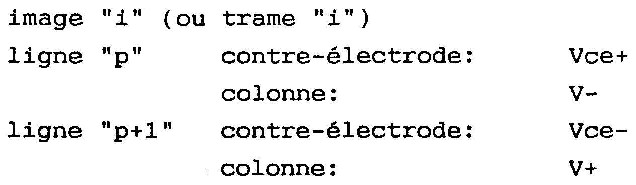
- the polarity of each fraction alternates between Vce + and Vce- values, the polarities of the two fractions being always opposite. This result can be achieved using a sequencer 30 controlled by a clock signal H at the frame frequency.
- the control mode of the switching elements can be the same as in the case of a conventional device of the kind shown in FIG. 2.
- the control voltages to which the column conductors, such as the conductor 24, will be applied providing the video information will depend, for a given result, on the column ordered.
Abstract
Description


Claims
Priority Applications (3)
| Application Number | Priority Date | Filing Date | Title |
|---|---|---|---|
| US08/199,291 US5448385A (en) | 1992-07-02 | 1993-07-01 | Active matrix liquid crystal display device with interdigitated counter electrodes |
| JP6503017A JPH06510609A (ja) | 1992-07-02 | 1993-07-01 | アクティブマトリックス液晶表示装置 |
| EP93914793A EP0602218A1 (fr) | 1992-07-02 | 1993-07-01 | Dispositif de visualisation a cristaux liquides, a matrice active |
Applications Claiming Priority (2)
| Application Number | Priority Date | Filing Date | Title |
|---|---|---|---|
| FR92/08159 | 1992-07-02 | ||
| FR929208159A FR2693305B1 (fr) | 1992-07-02 | 1992-07-02 | Dispositif de visualisation à cristaux liquides, à matrice active. |
Publications (1)
| Publication Number | Publication Date |
|---|---|
| WO1994001801A1 true WO1994001801A1 (fr) | 1994-01-20 |
Family
ID=9431453
Family Applications (1)
| Application Number | Title | Priority Date | Filing Date |
|---|---|---|---|
| PCT/FR1993/000668 WO1994001801A1 (fr) | 1992-07-02 | 1993-07-01 | Dispositif de visualisation a cristaux liquides, a matrice active |
Country Status (6)
| Country | Link |
|---|---|
| US (1) | US5448385A (fr) |
| EP (1) | EP0602218A1 (fr) |
| JP (1) | JPH06510609A (fr) |
| CA (1) | CA2116693A1 (fr) |
| FR (1) | FR2693305B1 (fr) |
| WO (1) | WO1994001801A1 (fr) |
Families Citing this family (12)
| Publication number | Priority date | Publication date | Assignee | Title |
|---|---|---|---|---|
| TW329500B (en) | 1995-11-14 | 1998-04-11 | Handotai Energy Kenkyusho Kk | Electro-optical device |
| JPH09146108A (ja) * | 1995-11-17 | 1997-06-06 | Semiconductor Energy Lab Co Ltd | 液晶表示装置およびその駆動方法 |
| US6055028A (en) * | 1996-02-14 | 2000-04-25 | Semiconductor Energy Laboratory Co., Ltd. | Liquid crystal electro-optical device |
| US6697129B1 (en) * | 1996-02-14 | 2004-02-24 | Semiconductor Energy Laboratory Co., Ltd. | Guest-host mode liquid crystal display device of lateral electric field driving type |
| JP3708620B2 (ja) * | 1996-03-01 | 2005-10-19 | 株式会社半導体エネルギー研究所 | アクティブマトリクス型液晶電気光学装置 |
| JP3788649B2 (ja) * | 1996-11-22 | 2006-06-21 | 株式会社半導体エネルギー研究所 | 液晶表示装置 |
| JPH10186313A (ja) * | 1996-12-25 | 1998-07-14 | Furontetsuku:Kk | カラー液晶表示装置 |
| GB2323204A (en) * | 1997-03-15 | 1998-09-16 | Sharp Kk | Spatial light modulator and display |
| KR100293806B1 (ko) * | 1997-06-25 | 2001-10-24 | 박종섭 | 액정표시소자 |
| US6489952B1 (en) * | 1998-11-17 | 2002-12-03 | Semiconductor Energy Laboratory Co., Ltd. | Active matrix type semiconductor display device |
| FR2787910B1 (fr) * | 1998-12-23 | 2001-03-16 | Sextant Avionique | Circuit de commande d'ecran a cristaux liquides |
| KR100713882B1 (ko) * | 2000-12-01 | 2007-05-07 | 비오이 하이디스 테크놀로지 주식회사 | Ffs 모드 박막트랜지스터 액정표시장치 |
Citations (4)
| Publication number | Priority date | Publication date | Assignee | Title |
|---|---|---|---|---|
| GB2064194A (en) * | 1978-02-08 | 1981-06-10 | Sharp Kk | A matrix type liquid crystal display device |
| EP0224388A2 (fr) * | 1985-11-22 | 1987-06-03 | Nec Corporation | Dispositif de visualisation à cristaux liquides à matrice active |
| EP0287996A2 (fr) * | 1987-04-20 | 1988-10-26 | Hitachi, Ltd. | Dispositif d'affichage à cristaux liquides et sa méthode de contrôle |
| EP0362948A2 (fr) * | 1988-10-07 | 1990-04-11 | Philips Electronics Uk Limited | Dispositif d'affichage à matrice |
Family Cites Families (3)
| Publication number | Priority date | Publication date | Assignee | Title |
|---|---|---|---|---|
| FR2571526B1 (fr) * | 1984-08-22 | 1991-02-08 | Canon Kk | Panneau d'affichage et son procede de commande |
| FR2590394B1 (fr) * | 1985-11-15 | 1987-12-18 | Thomson Csf | Ecran de visualisation electro-optique a transistors de commande |
| JPH02116892A (ja) * | 1988-10-27 | 1990-05-01 | Toshiba Corp | 液晶表示装置 |
-
1992
- 1992-07-02 FR FR929208159A patent/FR2693305B1/fr not_active Expired - Fee Related
-
1993
- 1993-07-01 WO PCT/FR1993/000668 patent/WO1994001801A1/fr not_active Application Discontinuation
- 1993-07-01 CA CA002116693A patent/CA2116693A1/fr not_active Abandoned
- 1993-07-01 US US08/199,291 patent/US5448385A/en not_active Expired - Fee Related
- 1993-07-01 JP JP6503017A patent/JPH06510609A/ja active Pending
- 1993-07-01 EP EP93914793A patent/EP0602218A1/fr not_active Ceased
Patent Citations (4)
| Publication number | Priority date | Publication date | Assignee | Title |
|---|---|---|---|---|
| GB2064194A (en) * | 1978-02-08 | 1981-06-10 | Sharp Kk | A matrix type liquid crystal display device |
| EP0224388A2 (fr) * | 1985-11-22 | 1987-06-03 | Nec Corporation | Dispositif de visualisation à cristaux liquides à matrice active |
| EP0287996A2 (fr) * | 1987-04-20 | 1988-10-26 | Hitachi, Ltd. | Dispositif d'affichage à cristaux liquides et sa méthode de contrôle |
| EP0362948A2 (fr) * | 1988-10-07 | 1990-04-11 | Philips Electronics Uk Limited | Dispositif d'affichage à matrice |
Also Published As
| Publication number | Publication date |
|---|---|
| CA2116693A1 (fr) | 1994-01-20 |
| FR2693305A1 (fr) | 1994-01-07 |
| US5448385A (en) | 1995-09-05 |
| EP0602218A1 (fr) | 1994-06-22 |
| JPH06510609A (ja) | 1994-11-24 |
| FR2693305B1 (fr) | 1994-09-30 |
Similar Documents
| Publication | Publication Date | Title |
|---|---|---|
| EP0332476B1 (fr) | Ecran d'affichage en couleur à matrice active sans croisement des conducteurs lignes d'adressage et des conducteurs colonnes de commande | |
| TWI296346B (en) | Active element substrate and liquid crystal display device using the same | |
| FR2542119A1 (fr) | Procede pour commander un ecran d'affichage matriciel a cristaux liquides | |
| FR2625357A1 (fr) | Configuration de pixels pour obtenir une triade en couleur en quinconce | |
| WO1994001801A1 (fr) | Dispositif de visualisation a cristaux liquides, a matrice active | |
| FR2553218A1 (fr) | Ecran d'affichage a matrice active sans croisement des lignes et des colonnes d'adressage | |
| EP2439583B1 (fr) | Afficheur a cristal liquide de type transmissif en technologie CMOS avec capacité de stockage auxiliaire | |
| FR2900492A1 (fr) | Ecran electroluminescent organique | |
| EP2721598B1 (fr) | Afficheur a cristal liquide a electrodes d'effacement | |
| KR960008099B1 (ko) | 매트릭스 디스플레이 장치 | |
| FR2611389A1 (fr) | Dispositif imageur matriciel a cristaux liquides a resolution doublee par birefringence | |
| EP0976122B1 (fr) | Dispositif d'adressage d'un ecran matriciel | |
| CA1196415A (fr) | Dispositif d'affichage matriciel a plusieurs jeux d'electrodes et son procede de commande | |
| FR2736733A1 (fr) | Dispositif d'affichage a cristaux liquides procede d'utilisation d'un tel dispositif | |
| EP0487389A1 (fr) | Ecran plat à matrice active | |
| FR2973119A1 (fr) | Dispositif d'affichage a cristaux liquides et procede de commande de ce dispositif | |
| EP0564337A1 (fr) | Ecran d'affichage à masque optique et procédé de réalisation de cet écran | |
| JPS6348077B2 (fr) | ||
| JP2613209B2 (ja) | 画像表示装置 | |
| FR2605778A1 (fr) | Panneau de visualisation a cristaux liquides et procede d'inscription des donnees sur ce panneau | |
| FR2722603A1 (fr) | Dispositif de visualisation a cristaux liquides, a matrice active et a contre-electrode fractionnee | |
| KR100518407B1 (ko) | 액정표시장치의 어레이 구조 및 그 구동방법 | |
| JPS61275822A (ja) | 液晶表示装置の駆動方法 | |
| EP0506530A1 (fr) | Ecran matriciel à définition améliorée et procédé d'adressage d'un tel écran | |
| FR2719936A1 (fr) | Dispositif de visualisation à cristaux liquides, à matrice active. |
Legal Events
| Date | Code | Title | Description |
|---|---|---|---|
| AK | Designated states |
Kind code of ref document: A1 Designated state(s): CA JP US |
|
| AL | Designated countries for regional patents |
Kind code of ref document: A1 Designated state(s): AT BE CH DE DK ES FR GB GR IE IT LU MC NL PT SE |
|
| WWE | Wipo information: entry into national phase |
Ref document number: 2116693 Country of ref document: CA |
|
| WWE | Wipo information: entry into national phase |
Ref document number: 1993914793 Country of ref document: EP Ref document number: 08199291 Country of ref document: US |
|
| 121 | Ep: the epo has been informed by wipo that ep was designated in this application | ||
| WWP | Wipo information: published in national office |
Ref document number: 1993914793 Country of ref document: EP |
|
| WWR | Wipo information: refused in national office |
Ref document number: 1993914793 Country of ref document: EP |
|
| WWW | Wipo information: withdrawn in national office |
Ref document number: 1993914793 Country of ref document: EP |