US9902244B2 - Arrangement comprising a cover for a vehicle roof - Google Patents
Arrangement comprising a cover for a vehicle roof Download PDFInfo
- Publication number
- US9902244B2 US9902244B2 US15/309,771 US201515309771A US9902244B2 US 9902244 B2 US9902244 B2 US 9902244B2 US 201515309771 A US201515309771 A US 201515309771A US 9902244 B2 US9902244 B2 US 9902244B2
- Authority
- US
- United States
- Prior art keywords
- cover
- deployment
- slotted link
- arrangement
- lever
- Prior art date
- Legal status (The legal status is an assumption and is not a legal conclusion. Google has not performed a legal analysis and makes no representation as to the accuracy of the status listed.)
- Active
Links
Images


Classifications
-
- B—PERFORMING OPERATIONS; TRANSPORTING
- B60—VEHICLES IN GENERAL
- B60J—WINDOWS, WINDSCREENS, NON-FIXED ROOFS, DOORS, OR SIMILAR DEVICES FOR VEHICLES; REMOVABLE EXTERNAL PROTECTIVE COVERINGS SPECIALLY ADAPTED FOR VEHICLES
- B60J7/00—Non-fixed roofs; Roofs with movable panels, e.g. rotary sunroofs
- B60J7/02—Non-fixed roofs; Roofs with movable panels, e.g. rotary sunroofs of sliding type, e.g. comprising guide shoes
- B60J7/04—Non-fixed roofs; Roofs with movable panels, e.g. rotary sunroofs of sliding type, e.g. comprising guide shoes with rigid plate-like element or elements, e.g. open roofs with harmonica-type folding rigid panels
- B60J7/043—Sunroofs e.g. sliding above the roof
- B60J7/0435—Sunroofs e.g. sliding above the roof pivoting upwardly to vent mode and moving at the outside of the roof to fully open mode
-
- B—PERFORMING OPERATIONS; TRANSPORTING
- B60—VEHICLES IN GENERAL
- B60J—WINDOWS, WINDSCREENS, NON-FIXED ROOFS, DOORS, OR SIMILAR DEVICES FOR VEHICLES; REMOVABLE EXTERNAL PROTECTIVE COVERINGS SPECIALLY ADAPTED FOR VEHICLES
- B60J7/00—Non-fixed roofs; Roofs with movable panels, e.g. rotary sunroofs
- B60J7/02—Non-fixed roofs; Roofs with movable panels, e.g. rotary sunroofs of sliding type, e.g. comprising guide shoes
- B60J7/024—Non-fixed roofs; Roofs with movable panels, e.g. rotary sunroofs of sliding type, e.g. comprising guide shoes characterised by the height regulating mechanism of the sliding panel
-
- B—PERFORMING OPERATIONS; TRANSPORTING
- B60—VEHICLES IN GENERAL
- B60J—WINDOWS, WINDSCREENS, NON-FIXED ROOFS, DOORS, OR SIMILAR DEVICES FOR VEHICLES; REMOVABLE EXTERNAL PROTECTIVE COVERINGS SPECIALLY ADAPTED FOR VEHICLES
- B60J7/00—Non-fixed roofs; Roofs with movable panels, e.g. rotary sunroofs
- B60J7/02—Non-fixed roofs; Roofs with movable panels, e.g. rotary sunroofs of sliding type, e.g. comprising guide shoes
- B60J7/04—Non-fixed roofs; Roofs with movable panels, e.g. rotary sunroofs of sliding type, e.g. comprising guide shoes with rigid plate-like element or elements, e.g. open roofs with harmonica-type folding rigid panels
- B60J7/043—Sunroofs e.g. sliding above the roof
Definitions
- the invention relates to an arrangement with a cover for a vehicle roof, which cover, starting from a closed position for closing a roof opening, can be raised for opening using deployment means in the rear region thereof and which cover can be displaced toward the rear over the vehicle roof into an open position.
- Such arrangements having a cover for a vehicle roof are known in many forms from the prior art.
- a drive carriage is displaced toward the rear in the vehicle longitudinal direction.
- deployment means are provided in order to raise the cover into a venting position before said cover is displaced further to the rear into an open position in order to open the roof opening.
- the deployment means which typically have components such as levers, bearings and/or slotted links, require corresponding structural space in order to make it possible to perform the opening process, which sometimes reduces the space in a passenger compartment of a vehicle.
- An object forming the basis of the invention is to describe an arrangement with a cover for a vehicle roof which is distinguished by the fact that it takes up little structural space.
- a cover for a vehicle roof which cover, starting from a closed position for closing a roof opening, can be raised in the rear region thereof for opening using deployment means and which cover can be displaced toward the rear over the vehicle roof into an open position.
- the deployment means have a sliding carriage which can be displaced in a guide rail along the vehicle longitudinal direction by means of a drive.
- the deployment means furthermore have a rear deployment lever with respect to the vehicle longitudinal direction, which rear deployment lever is pivotably coupled to the cover and which rear deployment lever is pivotably coupled to a bearing which is stationary fixed with respect to the guide rail and which rear deployment lever has a first coupling element.
- the deployment means furthermore have a deployment rod which is pivotably coupled by way of the first coupling element to the rear deployment lever and which deployment rod is, by way of the sliding carriage, displaceable in the vehicle longitudinal direction for the deployment of the rear deployment lever.
- the stationary fixed bearing is arranged such that a pivot axis of the stationary fixed bearing is arranged above a base of the guide rail, and wherein the deployment rod is coupled to the first coupling element such that, starting from the closed position of the cover, during a displacement of the sliding carriage along the vehicle longitudinal direction, the deployment rod overruns the fixed bearing.
- the displacement of the cover over the vehicle roof means that the cover, after lifting or deployment in the region of a rear edge of the cover, is pushed over an outer side of the vehicle roof.
- the arrangement is an arrangement for a spoiler roof.
- the location indications or directional indications used relate to the vehicle longitudinal direction.
- the vehicle longitudinal direction may also be referred to as the horizontal direction or X direction.
- the deployment or lifting of the cover is carried out substantially in a vertical direction or Z direction.
- the rear region of the cover is intended, for example, to be understood to be the region which, starting from a center of the cover, faces the rear of the vehicle.
- a base of the guide rail is to be understood to mean a plane which runs approximately parallel to a vehicle roof of the vehicle below the sliding carriage.
- the base denotes that region of the guide rail which, in the closed position of the cover, has the greatest spacing to the cover in a vertical direction.
- the deployment rod For the deployment of the rear deployment lever, the deployment rod is displaced rearward in the vehicle longitudinal direction.
- the rear deployment lever is pivoted relative to the pivot axis of the fixed bearing.
- the deployment rod overruns the fixed bearing, in order that the deployment rod does not collide with the fixed bearing.
- “overruns” means that, during the displacement of the sliding carriage, the deployment rod, at least in the rear region, performs a vertical movement, that is to say a movement in the Z direction.
- the fixed bearing is arranged substantially at the same height as the deployment rod in the closed position of the cover. During a displacement of the deployment rod, said deployment rod is guided over the bearing.
- the arrangement makes it possible for the required structural space to be considerably reduced, in particular because the fixed bearing does not have to be arranged below the base of the guide rail. In this way, when the arrangement is used in a vehicle, the space in a passenger compartment can be enlarged, which makes it possible, for example, to realize a greater amount of headroom for occupants of the vehicle. Furthermore, by way of the arrangement, so-called “water pockets” are avoided. If the fixed bearing were arranged below the base of the guide rail, it would be necessary, in the roof construction of the vehicle, to provide a recess formed in the direction of gravitational force, in which recess water can collect. Said water would be dischargeable only with difficulty and would for example promote corrosion of components.
- the deployment rod has, for the coupling to the rear deployment lever, a first slotted link which engages with the first coupling element of the rear deployment lever, such that, starting from the closed position of the cover, during a displacement of the sliding carriage, the first slotted link controls a deployment of the cover.
- the first slotted link Through the provision of the first slotted link, it is made possible for the cover to be deployed or raised with particularly low friction and with the lowest possible forces.
- the deployment rod may be produced in one piece with the first slotted link.
- the first slotted link has in the closed position of the cover a path in which, toward the rear in the vehicle longitudinal direction, a spacing between the first slotted link and the cover initially varies and subsequently remains constant.
- the variation of the spacing is to be understood to mean a significant change of the spacing, wherein the path extends for example in a curved, ramp-like or step-like manner.
- the spacing remaining constant is intended in this instance to be understood to mean that the spacing does not change at all, or only to a very small degree, for example, at a small angle with respect to the vehicle longitudinal direction.
- the spacing with respect to the cover may increase or decrease toward the rear.
- a path of the first slotted link in the closed position of the cover, has a front section, which runs substantially vertically, a middle section, in which a spacing between the first slotted link and the cover increases toward the rear in a vehicle longitudinal direction, and a rear section, in which the spacing between the first slotted link and the cover remains constant.
- the spacing remaining constant and variation of the spacing are to be understood analogously to the description given above.
- the first coupling element of the rear deployment lever is arranged close to the pivotable coupling between the rear deployment lever and the cover, in particular closer to the aforementioned pivotable coupling than to the pivotable coupling between the rear deployment lever and the fixed bearing.
- the deployment rod In the deployed state, for example in the venting position of the cover, the deployment rod is locked in an X direction relative to the guide rail.
- the deployment rod In the deployed state, for example in the venting position of the cover, the deployment rod is locked in an X direction relative to the guide rail.
- the deployment rod must accommodate the forces of the cover in particular in the X direction. Said forces are very much dependent on a lever moment between the first coupling element and the pivot axis of the fixed bearing.
- the first coupling element is arranged close to the pivotable coupling between the rear deployment lever and the cover, a greater lever moment is realized in relation to a coupling element which is arranged close to the visible coupling between the rear deployment lever and the fixed bearing, that is to say close to the pivot axis.
- a coupling element which is arranged close to the visible coupling between the rear deployment lever and the fixed bearing, that is to say close to the pivot axis.
- the fixed bearing is arranged below the base of the guide rail and the deployment rod is displaced substantially parallel to the vehicle longitudinal direction or parallel to the roof lining, a large lever moment would be generated.
- the large lever moment has the advantage that the deployment rod must accommodate less force in order to accommodate forces in the X direction and ensure the locking in the X direction. Accordingly, the deployment rod can also be dimensioned to be smaller, whereby, inter alia, it is possible for production and material costs to be saved.
- the arrangement furthermore has a second slotted link which is fixed with respect to the guide rail.
- the deployment rod has a second coupling element which engages with the second slotted link, such that, starting from a closed position of the cover, during a displacement of the sliding carriage, the second slotted link controls the overrun of the bearing secured to the vehicle.
- the deployment rod is, by way of the second coupling element, guided so as to be displaceable relative to the vehicle longitudinal direction and to the guide rail.
- the second slotted link controls the overrunning, that is to say, as mentioned in the introduction, the vertical raising of the deployment rod during the displacement of the sliding carriage over the fixed bearing.
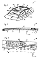
- FIG. 1 shows a schematic, perspective view of a vehicle
- FIG. 2 shows a side view of an arrangement with a cover for a vehicle roof of the vehicle
- FIG. 3 shows an enlarged, partially sectional side view of the arrangement in a closed position
- FIG. 4 shows an enlarged, partially sectional side view of the arrangement in a partial venting position
- FIG. 5 shows an enlarged, partially sectional side view of the arrangement in a venting position.
- FIG. 1 is a schematic, perspective view of a vehicle F having a vehicle roof FD.
- the vehicle roof FD has a securing section BA which is secured to the vehicle and which is constructed as a roof shell.
- the securing section BA which is secured to the vehicle is provided with a roof opening DOE which is selectively closed or at least partially openable by means of an adjustable movable roof element DE.
- the roof opening DOE is delimited by a roof frame section DRA which is constructed on the vehicle roof FD.
- the roof frame section DRA has guide rails FS which are preferably arranged at both sides.
- the roof element DE has a cover D and is supported so as to be displaceable relative to the guide rails FS in the region of the securing section BA.
- the roof element DE is displaceably supported by means of a cover carrier and arrangements AO in the guide rails FS.
- the cover D is preferably constructed as a glass cover.
- the arrangements AO which are arranged in the region of the guide rails FS serve to displace the cover D which closes the roof opening DOE of the vehicle roof FD from a closed position into an open position in order to thus open the roof opening DOE of the vehicle roof FD.
- the arrangements AO have deployment means.
- the cover D is pushed over a rear section of the vehicle roof FD.
- a rear edge HK of the cover D is first deployed. This intermediate position is also referred to as a venting position.
- the cover D thereafter is displaced in the vehicle longitudinal direction toward the rear, over the vehicle roof FD, into the open position.
- FIGS. 2 to 5 This typical movement sequence is carried out using the arrangements AO which are described in greater detail with reference to the following FIGS. 2 to 5 .
- FIGS. 2 to 5 in each case only one arrangement AO is illustrated at one side with the associated mechanism. However, all the components are arranged in a mirror-symmetrical manner with respect to a longitudinal center plane of the vehicle F at both sides of the roof opening DOE.
- the arrangement AO can also be referred to as a deployment device.
- FIGS. 2 to 5 illustrate only the cover carrier DT which is securely coupled mechanically to the cover D. Consequently, the cover D is directly coupled to the deployment means and can be moved by way of the latter. A displacement of the cover D is accordingly synonymous with a displacement of the cover carrier DT.
- FIGS. 2 to 5 each illustrate a coordinate system which indicates the directions Z and X.
- the X direction may in this case also be referred to as vehicle longitudinal direction or horizontal direction.
- the Z direction may also be referred to as vertical direction.
- FIG. 2 is a schematic side view of an arrangement AO.
- the arrangement AO comprises a sliding carriage S which can be displaced in a vehicle longitudinal direction in a guide rail FS (not illustrated) by means of a drive.
- the arrangement AO comprises a deployment rod AS, a fixed bearing L and a rear deployment lever HH.
- the rear deployment lever HH is pivotably connected to a slider G which is displaceably guided on the cover carrier DT.
- the rear deployment lever HH is thus pivotably coupled to the cover D.
- the closed position of the cover D is illustrated.
- the deployment rod AS is also displaced, parallel to the vehicle longitudinal direction, toward the rear, because the deployment rod AS is mechanically coupled to the sliding carriage S.
- the rear deployment lever HH is pivoted with respect to the bearing L so that the cover carrier DT or the cover D is deployed or raised in the region of the rear edge HK. In this state, the cover D is in the venting position. If the sliding carriage S is displaced further toward the rear, the sliding carriage S is decoupled from the deployment rod AS, wherein at the same time, the deployment rod AS is secured in a fixed manner with respect to the guide rail FS by means of a locking mechanism (not described in any more detail).
- the rear deployment lever HH is also locked in a fixed manner with respect to the guide rail FS in the deployed position. During the further displacement of the sliding carriage S, the latter drives the cover carrier DT along and pushes the cover carrier DT and consequently the cover D over the vehicle roof FD into the open position. As described, for this purpose, the rear deployment lever HH is displaceably coupled to the cover carrier DT via the slider G, such that the cover D can be displaced relative to the rear deployment lever HH.
- FIG. 3 shows the arrangement AO in the closed position of the cover D
- FIG. 4 shows the arrangement with a partially deployed cover D
- FIG. 5 shows the arrangement AO in a deployed state of the cover D or in the venting position.
- FIGS. 3 to 5 schematically illustrate in each case partially sectional side views of the arrangement AO.
- FIGS. 3 to 5 illustrate in each case a rear end of the deployment rod AS. Furthermore, the fixed bearing L, the rear deployment lever HH and the cover carrier DT are illustrated.
- the rear deployment lever HH is coupled, pivotably with respect to a first pivot axis SA 1 , to the fixed bearing L. Furthermore, the rear deployment lever HH is coupled, pivotably with respect to a second pivot axis SA 2 , to the slider G, which is guided so as to be in a relatively displaceable manner on the cover carrier DT.
- the deployment rod AS has, at the rear end thereof, a first slotted link K 1 .
- This is in engagement with a first coupling element KE 1 of the rear deployment lever HH.
- the first slotted link K 1 has a path in which, toward the rear in the vehicle longitudinal direction, a spacing between the first slotted link K 1 and the cover D initially varies and subsequently remains constant.
- the path has a front section VA 1 which extends substantially in a vertical manner.
- the path has a central section MA 1 in which the spacing between the first slotted link K 1 and the cover D increases toward the rear.
- first slotted link K 1 has a rear section HA 1 in which the spacing between the first slotted link K 1 and the cover D remains constant. In the closed position of the cover, the first coupling element KE 1 is located in the rear section HA 1 .
- the fixed bearing L of the arrangement AO is arranged in such a manner that the first pivot axis SA 1 of the fixed bearing L is located above a base B, indicated by dashed lines, of the guide rail FS.
- a base B of the guide rail FS is intended in this instance to be understood to be a plane normal with respect to the image plane of FIGS. 3 to 5 , which plane extends substantially tangentially to the vehicle roof FD underneath the sliding carriage S and has the largest spacing with respect to the cover D in the closed position.
- the sliding carriage S is displaceably arranged in the guide rail FS, wherein the guide rail FS extends tangentially with respect to the vehicle roof FD.
- the guide rail FS substantially comprises a C-profile which is open in an upward direction, that is to say in a direction facing the cover D in the Z direction, and inside which the sliding carriage S is guided.
- the deployment rod AS has a coupling element KE 2 by means of which the deployment rod AS is guided in a second slotted link K 2 which is fixed with respect to the guide rail FS.
- the second slotted link K 2 has, in the closed position of the cover D, a path with a front section VA 2 in which a spacing between the second slotted link K 2 and the cover D remains constant.
- the second slotted link K 2 has a central section MA 2 in which a spacing between the second slotted link K 2 and the cover D decreases toward the rear in the vehicle longitudinal direction.
- the second slotted link K 2 has a rear section HA 2 in which a spacing between the second slotted link K 2 and the cover D remains constant.
- the second coupling element KE 2 of the deployment rod AS is located in the front section VA 2 of the second slotted link K 2 .
- the deployment rod AS is displaced toward the rear as a result of the mechanical coupling with respect to the sliding carriage S.
- the second coupling element KE 2 of the second slotted link K 2 moves in the direction of the central section MA 2 .
- the rear deployment lever HH is initially not changed in terms of its position, that is to say not pivoted about the pivot axis SA 1 of the fixed bearing L. Rather, the deployment rod AS is displaced relative to the rear deployment lever HH, wherein the first coupling element KE 1 of the rear deployment lever HH is guided in the first slotted link K 1 in the direction of the central section MA 1 .
- the rear deployment lever HH is pivoted about the pivot axis SA 1 as a result of the movement of the sliding carriage S, whereby the cover carrier DT is raised in the region of the rear edge thereof.
- the deployment rod AS is, by means of the second slotted link K 2 , raised above the second coupling element KE 2 so as to perform a vertical movement in the Z direction in addition to the horizontal movement in the X direction.
- the cover carrier DT and consequently the cover D are now at least partially deployed. This is illustrated in FIG. 4 .
- the second coupling element KE 2 is guided in the second slotted link K 2 into the rear section HA 2 , and the first coupling element KE 1 is located in the front section VA 1 of the first slotted link K 1 .
- the cover D reaches its maximum deployed position (see FIG. 5 ).
- the deployment rod AS has, in the region of the rear end HE thereof in which the first slotted link K 1 is also arranged, overrun the fixed bearing L.
- the deployment rod AS has overrun a plane which is defined by the two pivot axes SA 1 and SA 2 in the closed position of the cover D.
- the deployment rod AS is locked in a fixed manner with respect to the guide rail FS by means of the locking mechanism and is decoupled from the sliding carriage S. In this way, the rear deployment lever HH is held in its position.
- the X-direction forces of the cover or of the cover carrier are in this case transmitted by the front section VA 1 of the first slotted link K 1 to the deployment rod AS.
- the first coupling element KE 1 is arranged very close to the coupling between the rear deployment lever HH and the slider G, that is to say the second pivot axis SA 2 , the first coupling element KE 1 is spaced apart to a very great extent from the first pivot axis SA 1 or from the coupling between the rear deployment lever HH and the fixed bearing L. In this way, a large lever is realized between the first coupling element KE 1 and the first pivot axis SA 1 .
- the deployment rod AS in the deployed position as per FIG.
- the drive of the sliding carriage S and the mechanical components, for example the deployment rod AS and/or the sliding carriage S itself, can be dimensioned to be smaller, which saves production costs, material costs and structural space.
- the coupling elements KE 1 and KE 2 are in the form of slide elements. All of the parts and elements illustrated may be modified and/or varied in terms of their explicit shaping, wherein the underlying mechanical and kinematic operating principle, as discussed here, of the arrangement AO should be maintained.
Landscapes
- Engineering & Computer Science (AREA)
- Mechanical Engineering (AREA)
- Fittings On The Vehicle Exterior For Carrying Loads, And Devices For Holding Or Mounting Articles (AREA)
- Body Structure For Vehicles (AREA)
Applications Claiming Priority (6)
| Application Number | Priority Date | Filing Date | Title |
|---|---|---|---|
| DE102014106813 | 2014-05-14 | ||
| DE102014106813 | 2014-05-14 | ||
| DE102014106813.0 | 2014-05-14 | ||
| DE102014109698.3A DE102014109698B3 (de) | 2014-05-14 | 2014-07-10 | Anordnung mit einem Deckel für ein Fahrzeugdach |
| DE102014109698.3 | 2014-07-10 | ||
| PCT/EP2015/058706 WO2015172987A1 (de) | 2014-05-14 | 2015-04-22 | Anordnung mit einem deckel für ein fahrzeugdach |
Publications (2)
| Publication Number | Publication Date |
|---|---|
| US20170267077A1 US20170267077A1 (en) | 2017-09-21 |
| US9902244B2 true US9902244B2 (en) | 2018-02-27 |
Family
ID=54250159
Family Applications (1)
| Application Number | Title | Priority Date | Filing Date |
|---|---|---|---|
| US15/309,771 Active US9902244B2 (en) | 2014-05-14 | 2015-04-22 | Arrangement comprising a cover for a vehicle roof |
Country Status (6)
| Country | Link |
|---|---|
| US (1) | US9902244B2 (de) |
| EP (1) | EP3142880B1 (de) |
| JP (1) | JP6410845B2 (de) |
| CN (1) | CN106457986B (de) |
| DE (1) | DE102014109698B3 (de) |
| WO (1) | WO2015172987A1 (de) |
Cited By (2)
| Publication number | Priority date | Publication date | Assignee | Title |
|---|---|---|---|---|
| US10792986B2 (en) | 2017-03-27 | 2020-10-06 | Webasto SE | Arrangement with a cover for a vehicle roof |
| US11318824B2 (en) | 2018-06-12 | 2022-05-03 | Webasto SE | Assembly for a cover of a vehicle roof, and vehicle roof for a motor vehicle |
Families Citing this family (7)
| Publication number | Priority date | Publication date | Assignee | Title |
|---|---|---|---|---|
| FR3073474B1 (fr) * | 2017-11-16 | 2019-10-18 | Renault S.A.S | Ensemble interieur support de charges d'un vehicule |
| DE102017129013A1 (de) * | 2017-12-06 | 2019-06-06 | Webasto SE | Dachanordnung für eine Dachöffnung eines Fahrzeugdachs und Verfahren zum Betreiben einer Dachanordnung |
| DE102017129040A1 (de) | 2017-12-06 | 2019-06-06 | Webasto SE | Vorrichtung für ein Fahrzeugdach und Verfahren zum Betreiben einer Vorrichtung für ein Fahrzeugdach |
| DE102018130017A1 (de) * | 2018-11-27 | 2020-05-28 | Roof Systems Germany Gmbh | Schiebedachsystem für ein Kraftfahrzeug |
| DE102019113142A1 (de) * | 2019-05-17 | 2020-11-19 | Webasto SE | Anordnung und Verfahren zum Bewegen eines Deckels |
| DE102019124081B3 (de) * | 2019-09-09 | 2021-02-11 | Webasto SE | Vorrichtung und Verfahren zum Sichern einer Bildschirmanordnung für ein Fahrzeugdach und Fahrzeugdach für ein Kraftfahrzeug |
| DE102021123230A1 (de) * | 2021-09-08 | 2023-03-09 | Webasto SE | Anordnung für ein Fahrzeugdach sowie Fahrzeugdach für ein Kraftfahrzeug |
Citations (13)
| Publication number | Priority date | Publication date | Assignee | Title |
|---|---|---|---|---|
| US4678228A (en) * | 1984-12-06 | 1987-07-07 | Vermeulen-Hollandia Octrooien Ii B.V. | Sliding roof for a vehicle |
| JPS63180420U (de) | 1987-05-14 | 1988-11-22 | ||
| US5058947A (en) * | 1988-12-08 | 1991-10-22 | Vermeulen-Hollandia Octrooien Ii B.V. | Sliding roof for a vehicle |
| JPH06199133A (ja) | 1992-09-24 | 1994-07-19 | Webast Heuliez | 細目に開いてスライドするサンルーフ |
| JP2004001605A (ja) | 2002-05-31 | 2004-01-08 | Aisin Seiki Co Ltd | ルーフ開閉装置 |
| EP1535780A2 (de) | 2003-11-27 | 2005-06-01 | Aisin Seiki Kabushiki Kaisha | Schiebedach |
| JP2005162064A (ja) | 2003-12-03 | 2005-06-23 | Aisin Seiki Co Ltd | サンルーフ装置 |
| EP2263897A1 (de) | 2009-06-16 | 2010-12-22 | Inalfa Roof Systems Group B.V. | Offene Dachkonstruktion für ein Fahrzeug |
| DE202010012974U1 (de) | 2010-11-24 | 2012-02-27 | Inalfa Roof Systems Group B.V. | Offendachkonstruktion für ein Fahrzeug |
| JP2012091582A (ja) | 2010-10-25 | 2012-05-17 | Yachiyo Industry Co Ltd | サンルーフ装置 |
| DE102011018151A1 (de) | 2011-04-19 | 2012-10-25 | Daimler Ag | Baugruppe für ein öffnungsfähiges Schiebedach |
| DE102012106545A1 (de) | 2012-07-19 | 2014-01-23 | Webasto SE | Verstellvorrichtung für einen Dachdeckel eines öffnungsfähigen Fahrzeugdachs |
| EP2727755A1 (de) | 2012-10-30 | 2014-05-07 | Inalfa Roof Systems Group B.V. | Offene Dachkonstruktion für ein Fahrzeug |
-
2014
- 2014-07-10 DE DE102014109698.3A patent/DE102014109698B3/de not_active Expired - Fee Related
-
2015
- 2015-04-22 US US15/309,771 patent/US9902244B2/en active Active
- 2015-04-22 JP JP2016567245A patent/JP6410845B2/ja active Active
- 2015-04-22 CN CN201580031834.1A patent/CN106457986B/zh active Active
- 2015-04-22 WO PCT/EP2015/058706 patent/WO2015172987A1/de not_active Ceased
- 2015-04-22 EP EP15717506.8A patent/EP3142880B1/de active Active
Patent Citations (17)
| Publication number | Priority date | Publication date | Assignee | Title |
|---|---|---|---|---|
| US4678228A (en) * | 1984-12-06 | 1987-07-07 | Vermeulen-Hollandia Octrooien Ii B.V. | Sliding roof for a vehicle |
| JPS63180420U (de) | 1987-05-14 | 1988-11-22 | ||
| US5058947A (en) * | 1988-12-08 | 1991-10-22 | Vermeulen-Hollandia Octrooien Ii B.V. | Sliding roof for a vehicle |
| JPH06199133A (ja) | 1992-09-24 | 1994-07-19 | Webast Heuliez | 細目に開いてスライドするサンルーフ |
| US5405185A (en) | 1992-09-24 | 1995-04-11 | Webasto-Heuliez | Tilt and slide sun-roof |
| JP2004001605A (ja) | 2002-05-31 | 2004-01-08 | Aisin Seiki Co Ltd | ルーフ開閉装置 |
| EP1535780A2 (de) | 2003-11-27 | 2005-06-01 | Aisin Seiki Kabushiki Kaisha | Schiebedach |
| US7344188B2 (en) | 2003-12-03 | 2008-03-18 | Aisin Seiki Kabushiki Kaisha | Sunroof device |
| JP2005162064A (ja) | 2003-12-03 | 2005-06-23 | Aisin Seiki Co Ltd | サンルーフ装置 |
| EP2263897A1 (de) | 2009-06-16 | 2010-12-22 | Inalfa Roof Systems Group B.V. | Offene Dachkonstruktion für ein Fahrzeug |
| JP2012091582A (ja) | 2010-10-25 | 2012-05-17 | Yachiyo Industry Co Ltd | サンルーフ装置 |
| DE202010012974U1 (de) | 2010-11-24 | 2012-02-27 | Inalfa Roof Systems Group B.V. | Offendachkonstruktion für ein Fahrzeug |
| DE102011018151A1 (de) | 2011-04-19 | 2012-10-25 | Daimler Ag | Baugruppe für ein öffnungsfähiges Schiebedach |
| US20130099528A1 (en) | 2011-04-19 | 2013-04-25 | Rainer Grimm | Assembly for an openable sliding roof |
| US8807646B2 (en) | 2011-04-19 | 2014-08-19 | Roof Systems Germany Gmbh | Assembly for an openable sliding roof |
| DE102012106545A1 (de) | 2012-07-19 | 2014-01-23 | Webasto SE | Verstellvorrichtung für einen Dachdeckel eines öffnungsfähigen Fahrzeugdachs |
| EP2727755A1 (de) | 2012-10-30 | 2014-05-07 | Inalfa Roof Systems Group B.V. | Offene Dachkonstruktion für ein Fahrzeug |
Non-Patent Citations (2)
| Title |
|---|
| International Search Report for PCT/EP2015/058706 dated Jun. 30, 2015; English translation submitted herewith (6 Pages). |
| Notification of Reasons for Refusal, Japanese Application No. 2016-567245, dated Dec. 5, 2017, together with English language summary thereof. |
Cited By (2)
| Publication number | Priority date | Publication date | Assignee | Title |
|---|---|---|---|---|
| US10792986B2 (en) | 2017-03-27 | 2020-10-06 | Webasto SE | Arrangement with a cover for a vehicle roof |
| US11318824B2 (en) | 2018-06-12 | 2022-05-03 | Webasto SE | Assembly for a cover of a vehicle roof, and vehicle roof for a motor vehicle |
Also Published As
| Publication number | Publication date |
|---|---|
| EP3142880B1 (de) | 2018-08-29 |
| JP2017515732A (ja) | 2017-06-15 |
| EP3142880A1 (de) | 2017-03-22 |
| JP6410845B2 (ja) | 2018-10-24 |
| DE102014109698B3 (de) | 2015-10-22 |
| WO2015172987A1 (de) | 2015-11-19 |
| US20170267077A1 (en) | 2017-09-21 |
| CN106457986B (zh) | 2019-05-21 |
| CN106457986A (zh) | 2017-02-22 |
Similar Documents
| Publication | Publication Date | Title |
|---|---|---|
| US9902244B2 (en) | Arrangement comprising a cover for a vehicle roof | |
| US9975409B2 (en) | Arrangement with a cover for a vehicle roof | |
| US9688126B2 (en) | Arrangement for a vehicle roof with a cover | |
| US10106020B2 (en) | Arrangement having a cover for a vehicle roof | |
| KR101477999B1 (ko) | 차량용 개방 루프 구조 | |
| US10106021B2 (en) | Arrangement comprising a cover for a vehicle roof | |
| CN106467010B (zh) | 用于机动车的车顶系统 | |
| US9776487B2 (en) | Vehicle roof which can be opened and which comprises a movable cover | |
| CN104709037A (zh) | 驱动机构和设置有驱动机构的开口车顶构造 | |
| CN102431426A (zh) | 用于车辆的顶部设备 | |
| JP6154562B1 (ja) | 車両ルーフ用カバーを含む機器 | |
| US20170050501A1 (en) | Sliding roof system for an automotive vehicle | |
| JP2016032984A (ja) | サンルーフ装置 | |
| US9981536B2 (en) | Assembly having a cover for a vehicle roof | |
| EP2711218B1 (de) | Antriebsmechanismus und damit ausgestattete offene Dachkonstruktion | |
| EP2263896B2 (de) | Offene Dachkonstruktion für ein Fahrzeug | |
| EP2105333B1 (de) | Dachanordnung für ein Fahrzeug und Verfahren zum Betreiben davon | |
| US20160031306A1 (en) | Arrangement of a cover of a folding-top compartment in a cabriolet | |
| CN107428230B (zh) | 具有用于车顶的顶盖的组件和用于机动车的车顶 | |
| US20250153550A1 (en) | Arrangement for a vehicle roof and vehicle roof | |
| US11731496B2 (en) | Vehicle roof comprising a bearing device for a cover | |
| CN107466271B (zh) | 具有用于车顶的顶盖的组件和用于机动车的车顶 | |
| CN118219797A (zh) | 具有盖的能打开的车顶 |
Legal Events
| Date | Code | Title | Description |
|---|---|---|---|
| AS | Assignment |
Owner name: WEBASTO SE, GERMANY Free format text: ASSIGNMENT OF ASSIGNORS INTEREST;ASSIGNOR:HOELZEL, DOMINIK;REEL/FRAME:040258/0726 Effective date: 20160915 |
|
| STCF | Information on status: patent grant |
Free format text: PATENTED CASE |
|
| CC | Certificate of correction | ||
| MAFP | Maintenance fee payment |
Free format text: PAYMENT OF MAINTENANCE FEE, 4TH YEAR, LARGE ENTITY (ORIGINAL EVENT CODE: M1551); ENTITY STATUS OF PATENT OWNER: LARGE ENTITY Year of fee payment: 4 |
|
| MAFP | Maintenance fee payment |
Free format text: PAYMENT OF MAINTENANCE FEE, 8TH YEAR, LARGE ENTITY (ORIGINAL EVENT CODE: M1552); ENTITY STATUS OF PATENT OWNER: LARGE ENTITY Year of fee payment: 8 |