US9859533B2 - Energy storage apparatus - Google Patents
Energy storage apparatus Download PDFInfo
- Publication number
- US9859533B2 US9859533B2 US14/297,487 US201414297487A US9859533B2 US 9859533 B2 US9859533 B2 US 9859533B2 US 201414297487 A US201414297487 A US 201414297487A US 9859533 B2 US9859533 B2 US 9859533B2
- Authority
- US
- United States
- Prior art keywords
- energy storage
- partition
- partition plate
- storage devices
- storage apparatus
- Prior art date
- Legal status (The legal status is an assumption and is not a legal conclusion. Google has not performed a legal analysis and makes no representation as to the accuracy of the status listed.)
- Active, expires
Links
Images


Classifications
-
- H01M2/0217—
-
- H—ELECTRICITY
- H01—ELECTRIC ELEMENTS
- H01M—PROCESSES OR MEANS, e.g. BATTERIES, FOR THE DIRECT CONVERSION OF CHEMICAL ENERGY INTO ELECTRICAL ENERGY
- H01M10/00—Secondary cells; Manufacture thereof
- H01M10/60—Heating or cooling; Temperature control
- H01M10/61—Types of temperature control
- H01M10/613—Cooling or keeping cold
-
- H—ELECTRICITY
- H01—ELECTRIC ELEMENTS
- H01M—PROCESSES OR MEANS, e.g. BATTERIES, FOR THE DIRECT CONVERSION OF CHEMICAL ENERGY INTO ELECTRICAL ENERGY
- H01M10/00—Secondary cells; Manufacture thereof
- H01M10/60—Heating or cooling; Temperature control
- H01M10/62—Heating or cooling; Temperature control specially adapted for specific applications
- H01M10/625—Vehicles
-
- H—ELECTRICITY
- H01—ELECTRIC ELEMENTS
- H01M—PROCESSES OR MEANS, e.g. BATTERIES, FOR THE DIRECT CONVERSION OF CHEMICAL ENERGY INTO ELECTRICAL ENERGY
- H01M10/00—Secondary cells; Manufacture thereof
- H01M10/60—Heating or cooling; Temperature control
- H01M10/65—Means for temperature control structurally associated with the cells
- H01M10/656—Means for temperature control structurally associated with the cells characterised by the type of heat-exchange fluid
- H01M10/6561—Gases
- H01M10/6563—Gases with forced flow, e.g. by blowers
-
- H01M2/1061—
-
- H01M2/1072—
-
- H01M2/1077—
-
- H—ELECTRICITY
- H01—ELECTRIC ELEMENTS
- H01M—PROCESSES OR MEANS, e.g. BATTERIES, FOR THE DIRECT CONVERSION OF CHEMICAL ENERGY INTO ELECTRICAL ENERGY
- H01M50/00—Constructional details or processes of manufacture of the non-active parts of electrochemical cells other than fuel cells, e.g. hybrid cells
- H01M50/10—Primary casings; Jackets or wrappings
- H01M50/102—Primary casings; Jackets or wrappings characterised by their shape or physical structure
- H01M50/103—Primary casings; Jackets or wrappings characterised by their shape or physical structure prismatic or rectangular
-
- H—ELECTRICITY
- H01—ELECTRIC ELEMENTS
- H01M—PROCESSES OR MEANS, e.g. BATTERIES, FOR THE DIRECT CONVERSION OF CHEMICAL ENERGY INTO ELECTRICAL ENERGY
- H01M50/00—Constructional details or processes of manufacture of the non-active parts of electrochemical cells other than fuel cells, e.g. hybrid cells
- H01M50/20—Mountings; Secondary casings or frames; Racks, modules or packs; Suspension devices; Shock absorbers; Transport or carrying devices; Holders
- H01M50/204—Racks, modules or packs for multiple batteries or multiple cells
- H01M50/207—Racks, modules or packs for multiple batteries or multiple cells characterised by their shape
- H01M50/209—Racks, modules or packs for multiple batteries or multiple cells characterised by their shape adapted for prismatic or rectangular cells
-
- H—ELECTRICITY
- H01—ELECTRIC ELEMENTS
- H01M—PROCESSES OR MEANS, e.g. BATTERIES, FOR THE DIRECT CONVERSION OF CHEMICAL ENERGY INTO ELECTRICAL ENERGY
- H01M50/00—Constructional details or processes of manufacture of the non-active parts of electrochemical cells other than fuel cells, e.g. hybrid cells
- H01M50/20—Mountings; Secondary casings or frames; Racks, modules or packs; Suspension devices; Shock absorbers; Transport or carrying devices; Holders
- H01M50/289—Mountings; Secondary casings or frames; Racks, modules or packs; Suspension devices; Shock absorbers; Transport or carrying devices; Holders characterised by spacing elements or positioning means within frames, racks or packs
- H01M50/291—Mountings; Secondary casings or frames; Racks, modules or packs; Suspension devices; Shock absorbers; Transport or carrying devices; Holders characterised by spacing elements or positioning means within frames, racks or packs characterised by their shape
-
- Y—GENERAL TAGGING OF NEW TECHNOLOGICAL DEVELOPMENTS; GENERAL TAGGING OF CROSS-SECTIONAL TECHNOLOGIES SPANNING OVER SEVERAL SECTIONS OF THE IPC; TECHNICAL SUBJECTS COVERED BY FORMER USPC CROSS-REFERENCE ART COLLECTIONS [XRACs] AND DIGESTS
- Y02—TECHNOLOGIES OR APPLICATIONS FOR MITIGATION OR ADAPTATION AGAINST CLIMATE CHANGE
- Y02E—REDUCTION OF GREENHOUSE GAS [GHG] EMISSIONS, RELATED TO ENERGY GENERATION, TRANSMISSION OR DISTRIBUTION
- Y02E60/00—Enabling technologies; Technologies with a potential or indirect contribution to GHG emissions mitigation
- Y02E60/10—Energy storage using batteries
-
- Y—GENERAL TAGGING OF NEW TECHNOLOGICAL DEVELOPMENTS; GENERAL TAGGING OF CROSS-SECTIONAL TECHNOLOGIES SPANNING OVER SEVERAL SECTIONS OF THE IPC; TECHNICAL SUBJECTS COVERED BY FORMER USPC CROSS-REFERENCE ART COLLECTIONS [XRACs] AND DIGESTS
- Y02—TECHNOLOGIES OR APPLICATIONS FOR MITIGATION OR ADAPTATION AGAINST CLIMATE CHANGE
- Y02P—CLIMATE CHANGE MITIGATION TECHNOLOGIES IN THE PRODUCTION OR PROCESSING OF GOODS
- Y02P70/00—Climate change mitigation technologies in the production process for final industrial or consumer products
- Y02P70/50—Manufacturing or production processes characterised by the final manufactured product
Definitions
- the present invention relates to an energy storage apparatus including one or more energy storage devices housed in an outer housing.
- Battery packs that include a plurality of energy storage apparatuses housed in a pack case are known.
- the plurality of energy storage apparatuses each include one or more energy storage devices (battery cells) housed in an outer housing (module case).
- Each energy storage apparatus included in the battery pack requires a configuration in which electrical insulation of the battery cells is maintained and heat from the battery cells is prevented from transferring to surrounding components.
- the plurality of battery cells are arranged spaced apart from each other in order to maintain electrical and heat insulation.
- Another energy storage apparatus is known that can further secure electrical and heat insulation when a plurality of battery cells are to be housed in a module case by using partition plates formed between the plurality of battery cells in the module case.
- An object of the present invention is to provide an energy storage apparatus including an outer housing having increased design flexibility and a configuration that is changeable according to different design requirements.
- An energy storage apparatus includes: one or more energy storage devices, each energy storage device having a side surface; and an outer housing that houses the one or more energy storage devices.
- the outer housing includes an attachment portion for attaching a partition plate adjacently to the side surface of the one or more energy storage devices.
- FIG. 1 is an external perspective view of an energy storage apparatus according to an embodiment of the present invention.
- FIG. 2 is an exploded perspective view illustrating structural components of the energy storage apparatus.
- FIG. 3 is an exploded perspective view illustrating structural components of a module unit.
- FIG. 4 is a transparent perspective view illustrating the inside of an energy storage device.
- FIG. 5 is an external perspective view of the energy storage device from below.
- FIG. 6 is a perspective view illustrating a configuration of a case main body.
- FIG. 7 is a perspective view illustrating a configuration in which partition plates are attached to the case main body.
- FIG. 8 is a cross sectional view at the line VIII-VIII illustrated in FIG. 7 of the case main body with the partition plate to be attached thereto.
- FIG. 9 is an enlarged view illustrating how the partition plate attaches to a support portion of the case main body.
- FIG. 10 is an enlarged view illustrating how the partition plate attaches to a partition portion of the case main body.
- FIG. 11 is a cross sectional view at the line XI-XI illustrated in FIG. 6 of the case main body with the energy storage devices, the partition plates, and the abutment member disposed therein.
- FIG. 12 is a perspective view illustrating a configuration of a battery pack including the energy storage apparatus.
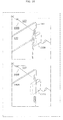
- FIG. 13 is a cross sectional view of the energy storage apparatus at the line XIII-XIII in FIG. 1 , illustrating the flow of air generated by a cooling apparatus when the partition plates are not provided in the center in the Y axis direction.
- FIG. 14 is a cross sectional view of the energy storage apparatus at the line XIV-XIV in FIG. 1 , illustrating the flow of air generated by the cooling apparatus when the partitions plates are only provided in the center in the Y axis direction.
- FIG. 15 illustrates how a partition plate attaches to a support portion of the case main body according to a first modified embodiment of the present invention.
- FIG. 16 illustrates how a partition plate attaches to a support portion of the case main body according to a second modified embodiment of the present invention.
- the configuration of an outer housing can be changed depending on design requirements such as electrical insulation and heat insulation.
- design requirements such as electrical insulation and heat insulation.
- the present invention was conceived in view of the above and aspects of the present invention provide an energy storage apparatus including an outer housing having increased design flexibility and a configuration that is changeable depending on design requirements.
- An energy storage apparatus includes: one or more energy storage devices, each energy storage device having a side surface; and an outer housing that houses the one or more energy storage devices.
- the outer housing includes an attachment portion for attaching a partition plate adjacently to the side surface of the one or more energy storage devices.
- the outer housing includes the attachment portion for attaching the partition plate adjacently to the side surface of the one or more energy storage devices, it is possible to selectively attach the partition plate to the outer housing.
- the partition plate can be selectively installed, or not installed, in the outer housing as needed. In this way, it is possible to flexibly alter the structure of the outer housing to suit the design requirements.
- the outer housing may include: a bottom surface; and a partition portion that extends from the bottom surface and is disposed adjacently to the side surface of the one or more energy storage devices.
- the outer housing may be configured such that the partition plate is disposed on an extension line of the partition portion.
- the outer housing includes the partition portion that extends from the bottom surface and is disposed adjacently to the side surface of the one or more energy storage devices, the one or more energy storage devices can easily be disposed in predetermined locations.
- the partition portion makes it possible to easily determine the positioning of the one or more energy storage devices in the outer housing.
- the partition portion may be continuously formed on the bottom surface and extend from a first side wall of the outer housing to a second side wall of the outer housing, the first and second side walls being opposite from each other and each being continuously formed on the bottom surface and intersecting the bottom surface.
- the partition portion is continuously formed on the bottom surface and extends from the first side wall of the outer housing to the second side wall of the outer housing, even if water from, for example, moisture, builds up on the first surface of the outer housing, it is possible to ensure electrical insulation of the container of the energy storage device and components disposed in the area surrounding the energy storage device (including the energy storage device).
- the attachment portion may include the partition portion, and the partition portion may include, at its tip end, a fitting portion for fitting a first end portion of the partition plate.
- the partition portion includes, in its tip end, a fitting portion for fitting a first end portion of the partition plate, it is possible to easily attach the partition plate to the outer housing simply by inserting the partition plate into the fitting portion of the partition portion.
- the outer housing may have an opening in a surface other than the bottom surface on which the partition portion is formed.
- the opening is formed in the outer housing in a surface thereof other than the bottom surface on which the partition portion is formed. Since the opening is formed in the side wall and not in the vicinity of the partition portion, the strength of the partition portion can be maintained.
- the partition portion may be made of a material different from that of the partition plate.
- the energy storage apparatus may further include the partition plate that is detachably attached to the attachment portion.
- the partition plate since the partition plate is detachably attached to the attachment portion, the partition plate can be attached or detached flexibly as needed.
- the partition plate may include an insulating member.
- the partition plate includes an insulating member, it is possible to insulate the one or more energy storage devices both thermally and electrically.
- the energy storage apparatus may include the plurality of energy storage devices that are arranged in a line, and the attachment portion may be formed between the energy storage devices such that the partition plate is attachable to the attachment portion.
- the partition plate may have a recessed section at its first end portion, and the partition portion may include a protruding section that is engageable with the recessed section, the protruding section being formed in the partition portion.
- the attachment portion may include a support portion in a position where at least one surface of the partition plate in a vicinity of its second end portion is abuttable.
- the support portion may have a groove for fitting a second end portion of the partition plate.
- the energy storage apparatus may further include an abutment member abutting the one or more energy storage devices.
- a second end portion of the partition plate may abut the abutment member.
- the partition plate spans the first axis width of the one or more energy storage devices, it is possible to increase the heat insulation between the one or more energy storage devices and conductive components.
- FIG. 1 is an external perspective view of the energy storage apparatus 1 according to the embodiment of the present invention.
- FIG. 2 is an exploded perspective view illustrating structural components of the energy storage apparatus 1 .
- the Z axis which is the first axis, is shown as being the vertical direction in FIG. 1 and FIG. 2 .
- the Z axis is exemplified as being the vertical direction in the following description as well, but depending on the mode of use, it is conceivable that the Z axis may be a direction other than the vertical direction. As such, the Z axis is not limited to the vertical direction.
- the energy storage apparatus 1 is an energy storage module capable of charging electricity from an external source and discharging electricity to an external device.
- the energy storage apparatus 1 is, for example, a high-voltage energy storage apparatus used to store energy and/or used as a power source.
- the energy storage apparatus 1 includes a module group 10 including module units 11 , 12 , and 13 , a lower coupling component 20 , an upper coupling component 30 , and a cooling apparatus 40 . It should be noted that the energy storage apparatus 1 may include only one module unit.
- the module units 11 , 12 , and 13 included in the module group 10 are aligned along the X axis.
- the module unit 11 includes an external positive terminal cover 11 a which covers the external positive terminal (to be described later) and an external negative terminal cover 11 b which covers the external negative terminal (to be described later).
- the energy storage apparatus 1 charges electricity from an external source and discharges electricity to an external device through the external positive terminal under the external positive terminal cover 11 a and the external negative terminal under the external negative terminal cover 11 b.
- the module units 11 , 12 , and 13 are rectangular modules including one or more energy storage devices housed in a module case 14 .
- Each of the module units 11 , 12 , and 13 has the same configuration.
- the positive terminals and negative terminals of adjacent ones of the module units 11 , 12 , and 13 are electrically connected, whereby all energy storage devices in the module units 11 , 12 , and 13 are connected in series.
- the configuration of the module units 11 , 12 , and 13 will be described in detail later.
- the lower coupling component 20 and the upper coupling component 30 are components which couple the module units 11 , 12 , and 13 together.
- the lower coupling component 20 couples the module units 11 , 12 , and 13 from below and the upper coupling component 30 couples the module units 11 , 12 , and 13 from above.
- fixing the lower coupling component 20 and the upper coupling component 30 together with the module units 11 , 12 , and 13 disposed therebetween couples the module units 11 , 12 , and 13 together.
- the lower coupling component 20 and the upper coupling component 30 are plate-like members formed, for example, from a conductive material such as metal. With this, the module units 11 , 12 , and 13 are firmly and securely fixed. It should be noted that since it is usually difficult to electrically insulate the surfaces of the lower coupling component 20 and the upper coupling component 30 with a coating, the lower coupling component 20 and the upper coupling component 30 have conductive properties.
- each module case 14 of the module units 11 , 12 , and 13 is mounted on the lower coupling component 20 .
- the cooling apparatus 40 is a fan that introduces a coolant into the module group 10 .
- the cooling apparatus 40 draws in outside air (the coolant) from the end of the module group 10 in the negative direction of the X axis, and introduces air into each module case 14 of the module units 11 , 12 , and 13 .
- the cooling apparatus 40 then expels the air from the end of the module group 10 in the positive direction of the X axis out the back of the cooling apparatus 40 .
- the cooling apparatus 40 may draw in outside air from the end of the module group 10 in the positive direction of the X axis and expel the air from the end of the module group 10 in the negative direction of the X axis.
- the coolant introduced into the module group 10 by the cooling apparatus 40 is not limited to atmospheric air.
- the coolant may be cold air chilled by a condenser.
- the cooling apparatus 40 is provided with two fans, but number of fans the cooling apparatus 40 has is not limited to this example. Still further, the cooling apparatus 40 is not limited to the use of a fan. As long as it introduces the coolant into the module group 10 , something other than a fan may be used.
- each of the module units 11 , 12 , and 13 have the same configuration. As such, the following description focuses on the module unit 11 , and descriptions of the module units 12 and 13 are omitted.
- FIG. 3 is an exploded perspective view illustrating structural components of the module unit 11 according to the embodiment of the present invention.
- the module unit 11 includes: the module case 14 including a case main body 100 and a cover 700 ; a plurality of energy storage devices 200 (in the embodiment, four of the energy storage devices 200 are provided) housed in the module case 14 ; a partition plate 140 ; an abutment member 300 ; bus bars 430 , and a substrate 600 .
- the plurality of energy storage devices 200 are aligned along the Y axis, which is the second axis. It should be noted that one energy storage device 200 may be housed in the module case 14 instead of a plurality of the energy storage devices 200 .
- the module case 14 is a rectangular (box-shaped) container acting as an outer housing for the module unit 11 .
- the module case 14 arranges the energy storage devices 200 and the substrate 600 and such in given positions and protects the energy storage devices 200 and the substrate 600 and such from impact.
- the module case 14 is made of a material having insulating properties, such as a resin, like polycarbonate, for example. This prevents the energy storage device 200 and the substrate 600 and such from coming into contact with, for example, external metal components.
- the module case 14 includes the case main body 100 and the cover 700 .
- the case main body 100 is a rectangular, tubular component having a bottom, and serves as the main body of the module case 14 .
- the cover 700 is a low-profile, rectangular component that covers the opening of the case main body 100 , and serves as the cover of the module case 14 .
- the energy storage devices 200 , the abutment member 300 , and the bus bars 430 are arranged in this order in the case main body 100 , and then the opening of the case main body 100 is closed off with the cover 700 . Arranging the heavy energy storage devices 200 on the bottom in this way improves the stability of the module unit 11 .
- the configuration of the case main body 100 will be described in detail later.
- the partition plate 140 is a flat component disposed between the energy storage devices 200 .
- the partition plate 140 is a component having electrical and heat insulating properties, and is formed, for example, by laminating sheets made of resin impregnated with a material such as fiberglass. It should be noted that the partition plate 140 is not limited to the above material, and may be formed of, for example resin that has at least either one of electrical or heat insulating properties.
- the partition plate 140 is a component disposed between the energy storage devices 200 to secure at least one of electrical and heat insulation between the energy storage devices 200 . More specifically, the partition plate 140 is attached to an attachment portion 134 (to be described later) provided in the case main body 100 .
- the abutment member 300 is a low-profile, rectangular component located above the energy storage devices 200 .
- the abutment member 300 is made of a material having insulating properties, such as resin.
- the abutment member 300 is a component that abuts the side of the energy storage devices 200 in the positive direction of the Z axis.
- the abutment member 300 may have a function of restricting the positioning of the energy storage devices 200 included in the case main body 100 . More specifically, the abutment member 300 may fit inside the case main body 100 and hold down the energy storage devices 200 from above to fix the energy storage devices 200 to the case main body 100 .
- the substrate 600 is mounted on the abutment member 300 .
- the abutment member 300 functions as a mounting plate for the substrate 600 in addition to functioning to fix the energy storage devices 200 to the case main body 100 .
- the bus bars 430 are arranged above the abutment member 300 .
- the bus bars 430 are made of a conductive material, such as metal, and electrically connect the energy storage devices 200 together. More specifically, the bus bar 430 connects the positive terminal or negative terminal of one of two adjacently arranged energy storage devices 200 to the negative terminal or positive terminal of the other of the two adjacently arranged energy storage devices 200 .
- the module unit 11 moreover includes an external positive terminal 410 arranged in the external positive terminal cover 11 a and an external negative terminal 420 arranged in the external negative terminal cover 11 b .
- the external positive terminal 410 and the external negative terminal 420 are electrode terminals for charging the energy storage apparatus 1 with electricity from an external source and discharging electricity to an external device.
- the energy storage apparatus 1 is charged with electricity from an external source and discharges electricity to an external device via the external positive terminal 410 and the external negative terminal 420 .
- the substrate 600 is a substrate capable of obtaining, monitoring, and controlling the state of the energy storage devices 200 , and is connected to the energy storage devices 200 via wiring 440 .
- the wiring 440 is a lead wire connecting the positive terminal 230 or the negative terminal 240 of the energy storage device 200 to the substrate 600 . It should be noted that the illustration of the wiring 440 is partially omitted in FIG. 3 .
- the substrate 600 is a control substrate for obtaining and monitoring, for example, the charging state and discharging state (the state of the battery, such as voltage or temperature) of the energy storage devices 200 .
- the substrate 600 is provided with a control circuit (not shown in the drawings) for performing the above-described monitoring, controlling the on and off states of a relay, or communicating with other devices.
- the substrate 600 is located on the abutment member 300 , and arranged so as to be covered by the cover 700 .
- the substrate 600 is arranged so as to be protected by the abutment member 300 and the cover 700 as a result of being sandwiched between the abutment member 300 and the cover 700 .
- integrating the electrical components in the upper portion of the energy storage apparatus 1 makes assembly and maintenance of the energy storage apparatus 1 easier.
- FIG. 4 is a transparent perspective view illustrating the inside of the energy storage device 200 according to the embodiment of the present invention.
- FIG. 5 is an external perspective view of the energy storage device 200 from below.
- the energy storage device 200 is a secondary battery (battery cell) capable of charging and discharging electricity. More specifically, the energy storage device 200 is a non-aqueous electrolyte secondary battery such as a lithium ion secondary battery. It should be noted that the energy storage device 200 is not limited to a non-aqueous electrolyte secondary battery. The energy storage device 200 may be a secondary battery other than a non-aqueous electrolyte secondary battery, such as a capacitor.
- the energy storage device 200 includes a container 210 , the positive terminal 230 , and the negative terminal 240 .
- the container 210 includes, as a top wall, a container lid 220 . Additionally, an electrode assembly 250 , a positive current collector 260 , and a negative current collector 270 are arranged in the container 210 . It should be noted that even though it is not shown in the drawings, the container 210 contains a liquid such as an electrolyte.
- the container 210 is configured of a rectangular, tubular metal chassis main body having a bottom, and a container lid 220 , which is metallic and hermetically seals the opening of the chassis main body. Moreover, after insertion of the electrode assembly 250 and such, the inside of the container 210 is sealed by, for example, welding the container lid 220 to the chassis main body. It should be noted that the material used for the container 210 is not particularly limited to a certain material, but is preferably a weldable metal such as stainless steel or aluminum.
- the container 210 includes a sheet 211 that has insulating properties and covers the battery side surfaces 210 a and 210 b , and a sheet 212 that has insulating properties and covers the battery bottom surface 210 c .
- the battery side surface 210 a is the long side surface of the container 210
- the battery side surface 210 b is the short side surface of the container 210
- the battery bottom surface 210 c is the bottom surface of the container 210 .
- the sheet 212 is an insulation sheet that, by covering the battery bottom surface 210 c , maintains electrical insulation and protects the battery bottom surface 210 c from being scratched.
- the sheet 211 is an insulation sheet that, by covering the battery side surfaces 210 a and 210 b , which are the side surfaces adjacent to the battery bottom surface 210 c , without covering the battery bottom surface 210 c , maintains electrical insulation and protects the battery side surfaces 210 a and 210 b from being scratched.
- a gap is present at the perimeter of the battery bottom surface 210 c , at the boundary of the sheet 211 and the sheet 212 .
- the sheet 211 and the sheet 212 are not required to have electrical insulating properties. Even in this case, the sheet 211 and the sheet 212 are effective in preventing scratches.
- the electrode assembly 250 is a power generating element capable of storing electricity, and includes a positive electrode, a negative electrode, and a separator. More specifically, the electrode assembly 250 is a wound electrode assembly formed by winding, into an oblong shape, a laminate including the negative electrode, the positive electrode, and the separator interposed therebetween. It should be noted that the electrode assembly 250 may be a stacked electrode assembly in which flat electrode plates are layered.
- the positive electrode is a long, belt-shaped positive electrode base material foil made of aluminum or an aluminum alloy with a positive electrode active material layer formed on a surface thereof.
- the negative electrode is a long, belt-shaped negative electrode base material foil made of copper or a copper alloy with a negative electrode active material layer formed on a surface thereof.
- the separator is a microporous sheet. It should be noted that the positive electrode, the negative electrode, and the separator used in the energy storage device 200 are not particularly different from conventional positive electrodes, negative electrodes, and separators, and so long as the performance of the energy storage device 200 is not inhibited, well-known materials may be used.
- the electrolyte (non-aqueous electrolyte) enclosed in the container 210 is not particular limited to a certain type; a variety of electrolytes may be used.
- the positive terminal 230 is an electrode terminal that is electrically connected to the positive electrode in the electrode assembly 250 via the positive current collector 260
- the negative terminal 240 is an electrode terminal that is electrically connected to the negative electrode in the electrode assembly 250 via the negative current collector 270 .
- Both the positive terminal 230 and the negative terminal 240 are connected to the container lid 220 .
- the positive terminal 230 and the negative terminal 240 are metallic electrode terminals for leading electricity stored in the electrode assembly 250 out of the energy storage device 200 and introducing electricity into the energy storage device 200 to be stored in the electrode assembly 250 .
- the positive terminal 230 of the energy storage device 200 positionally corresponding to the external positive terminal 410 is connected to the external positive terminal 410
- the negative terminal 240 of the same energy storage device 200 is connected to the positive terminal 230 of an adjacent energy storage device 200 .
- the negative terminal 240 of the energy storage device 200 positionally corresponding to the external negative terminal 420 is connected to the external negative terminal 420
- the positive terminal 230 of the same energy storage device 200 is connected to the negative terminal 240 of an adjacent energy storage device 200 .
- the positive terminal 230 or the negative terminal 240 of other energy storage devices 200 are connected to the negative terminal 240 or the positive terminal 230 of an adjacent energy storage device 200 .
- the positive current collector 260 is a rigid component having conductive properties that is electrically connected to the positive terminal 230 and the positive electrode, and positioned between the positive electrode of the electrode assembly 250 and a side wall of the container 210 . It should be noted that, similar to the positive electrode current collector foil of the positive electrode, the positive current collector 260 is made of aluminum.
- the negative current collector 270 is a rigid component having conductive properties that is electrically connected to the negative terminal 240 and the negative electrode of the electrode assembly 250 , and positioned between the negative electrode of the electrode assembly 250 and a side wall of the container 210 . It should be noted that, similar to the negative electrode current collector foil of the negative electrode, the negative current collector 270 is made of copper.
- FIG. 6 is a perspective view illustrating the configuration of the case main body 100 according to the embodiment of the present invention.
- FIG. 7 is a perspective view illustrating the configuration in which the partition plates 140 are attached to the case main body 100 .
- the case main body 100 includes a case bottom portion 110 , a case side wall portion 120 , and a plurality of partition portions 130 , and is a rectangular, tubular component having a bottom and an opening in the upper portion.
- the energy storage devices 200 are inserted through the opening in the upper portion of the case main body 100 and housed in the case main body 100 .
- the energy storage devices 200 are housed in the case main body 100 such that the container lid 220 faces upward (the positive direction of the X axis).
- the energy storage devices 200 are housed in the case main body 100 such that the battery bottom surfaces 210 c of the energy storage devices 200 are opposed to the case bottom portion 110 and the battery side surfaces 210 a and 210 b of the energy storage devices 200 are opposed to the case side wall portion 120 , the partition portions 130 , and the partition plates 140 .
- the case bottom portion 110 is the bottom surface of the case main body 100 , and is a flat, rectangular component.
- the case side wall portion 120 is a four-cornered tubular component made from four flat, rectangular side walls that cover the four sides of the case bottom portion 110 .
- the case main body 100 of the module case 14 includes the case bottom portion 110 as the bottom surface and a plurality of the partition portions 130 that extend from the case bottom portion 110 and are disposed adjacently to the side surfaces of the energy storage devices 200 so as to partition the bottom end portions of the energy storage devices 200 .
- the partition portions 130 are flat, rectangular components for partitioning the energy storage devices 200 disposed in the case main body 100 .
- Each of the partition portions 130 is continuous from, among the four rectangular, flat side walls of the case side wall portion 120 , one of the pair of side walls facing the direction of the X axis to the other.
- partition portions 130 are continuously formed on the bottom surface and extend from a first side wall of the module case 14 to a second side wall of the module case 14 , which are opposite from each other.
- the first and second walls are each continuously formed on the bottom surface and intersect the bottom surface.
- each of the pair of side walls has openings 150
- each side wall in the pair of side walls facing the direction of the Y axis has openings 151 .
- the case main body 100 includes the attachment portions 134 for attachment of the partition plates 140 to the case main body 100 .
- the attachment portions 134 include the partition portions 130 .
- Each partition portion 130 includes, at its tip end, as the fitting portion, a groove 131 for fitting the end portion 142 of each partition plate 140 .
- the partition portions 130 include, on both side surfaces, protrusions 132 .
- the protrusions 132 restrict the positions of the energy storage devices 200 along the Y axis by abutting the battery side surfaces 210 a of the energy storage devices 200 .
- the protrusions 132 have a function of preventing the partition portions 130 from warping.
- the attachment portions 134 may further include pairs of support portions 133 formed in portions of the case side wall 120 located in the positive direction of the Z axis, from both X axis sides of the partition portions 130 .
- the pairs of support portions 133 positionally correspond to respective partition portions 130
- Each support portion 133 has a groove 133 a for fitting a protrusion 141 , which is a second end portion of the partition plate 140 .
- each of the partition plates 140 attaches to the case main body 100 by being inserted and engaging with the groove 131 formed in the partition portion 130 and the groove 133 a formed in the support portion 133 .
- the support portion 133 may be formed on only one of the two sides facing the direction of the X axis instead of on both sides.
- FIG. 8 is a cross sectional view at the line VIII-VIII illustrated in FIG. 7 of the case main body 100 with the partition plate 140 attached thereto and a side portion 152 of the case side wall portion 120 .
- the partition plate 140 includes the pair of protrusions 141 in the end portion in the positive direction of the Z axis.
- the protrusions extend from both sides in the direction of the X axis.
- the partition plate 140 has a plurality of cut-out sections 143 and cut-out sections 144 (recessed sections) at its first end portion.
- the case main body 100 is provided with (i) the support portions 133 including the grooves 133 a for engaging the pair of protrusions 141 of the partition plate 140 and (ii) the partition portion 130 including the groove 131 in which the end portion 142 of the partition plate 140 in the negative direction of the Z axis is inserted.
- the partition portion 130 of the case main body 100 includes ridges 131 a (protruding sections) for further engagement with the cut-out sections 143 of the partition plate 140 .
- the groove 133 a formed in the support portion 133 includes a bottom surface 133 b that supports the side of the protrusion 141 of the partition plate 140 located in the negative direction of the Z axis.
- the partition plate 140 can also be supported at the protrusion 141 formed at the end portion of the partition plate 140 in the positive direction of the Z axis. This makes it possible to prevent warping where the end portion located on the side of the partition plate 140 in the positive direction of the Z axis moves closer to the end portion located in the negative direction of the Z axis.
- FIG. 9 is an enlarged view illustrating how the partition plate 140 attaches to the support portion 133 of the case main body 100 according to the embodiment of the present invention.
- FIG. 10 is an enlarged view illustrating how the partition plate 140 attaches to the partition portion 130 of the case main body 100 .
- FIG. 9 illustrates the state before the partition plate 140 is inserted into the groove 133 a of the support portion 133
- (b) illustrates the state after the partition plate 140 is inserted into the groove 133 a of the support portion 133 .
- the protrusion 141 of the partition plate 140 slides into the groove 133 a of the support portion 133 provided on the case side wall 120 of the case main body 100 .
- (b) in FIG. 9 illustrates the state before the partition plate 140 is inserted into the groove 133 a of the support portion 133 .
- FIG. 10 illustrates the state before the partition plate 140 is inserted into the groove 131 of the partition portion 130
- (b) illustrates the state after the partition plate 140 is inserted into the groove 131 of the partition portion 130 .
- the end portion 142 of the partition plate 140 located in the negative direction of the Z axis slides into the groove 131 of the partition portion 130 of the case main body 100 .
- the partition plate 140 and the groove 131 of the partition portion 130 are engaged while the end portion 142 of the partition plate 140 abuts the bottom surface of the groove 131 .
- the partition plate 140 engages with the grooves 131 and 133 a formed in the partition portion 130 and the support portion 133 , respectively, which are included in the attachment portion 134 of the case main body 100 , to attach to the case main body 100 .
- the partition plate 140 is detachably attached to the attachment portion 134 of the case main body 100 .
- FIG. 11 is a cross sectional view at the line XI-XI illustrated in FIG. 6 of the case main body 100 with the energy storage devices 200 , the partition plates 140 , and the abutment member 300 disposed therein.
- the abutment member 300 includes a partition portion 310 that is positioned between the energy storage devices 200 and extends in the negative direction of the Z axis.
- a rectangular protrusion 311 is formed on both side surfaces of the partition portion 310 formed on the abutment member 300 , similar to the protrusions 132 of the partition portions 130 formed on the case main body 100 .
- the protrusions 311 restrict the positions of the energy storage devices 200 along the Y axis by abutting the battery side surfaces 210 a of the energy storage devices 200 .
- the protrusions 311 have a function of preventing the partition portions 310 from warping.
- the end portion of the partition plate 140 located in the positive direction of the Z axis extends to the vicinity of the end portion of the partition portion 310 of the abutment member 300 located in the negative direction of the Z axis. It should be noted that the end portion of the partition plate 140 located in the positive direction of the Z axis may abut the end portion of the partition portion 310 of the abutment member 300 located in the negative direction of the Z axis. In this way, since the partition plates 140 are disposed between the energy storage devices 200 across the Z axis direction, electrical and heat insulation between the energy storage devices 200 can be, with certainty, increased. Moreover, by abutting the abutment member 300 with the partition plate 140 , the partition plate 140 can easily be secured, and vibration of the partition plate 140 can be prevented.
- FIG. 12 is a perspective view illustrating the configuration of a battery pack 2 including the energy storage apparatus 1 according to the embodiment of the present invention.
- the battery pack 2 is a large power source apparatus in which a plurality of energy storage apparatuses 1 (for example, ten to forty) are arranged in an array.
- the battery pack 2 is used to store energy and/or used as a power source, for example.
- the battery pack 2 includes a plurality of the energy storage apparatuses 1 and a pack case 2 a that houses the plurality of energy storage apparatuses 1 .
- the external positive terminals 410 and external negative terminals 420 of adjacent ones of the energy storage apparatuses 1 are electrically connected together to form the high-voltage battery pack 2 . It should be noted that the number of energy storage apparatuses 1 included in the battery pack 2 is not particularly limited to a given number.
- the case main body 100 of the module case 14 is provided with the attachment portions 134 for attaching the partition plates 140 between the energy storage devices 200 , it is possible to selectively attach the partition plates 140 to the case main body 100 .
- the module case 14 has a structure in which the transfer of heat from the energy storage devices 200 to nearby components (in particular, to an adjacent energy storage device) is inhibited.
- the partition plate 140 has insulating properties, it is possible to improve the insulation of the heat from the energy storage devices 200 and the electrical insulation of the energy storage devices 200 .
- partition plates 140 are provided to be detachably attachable to the plurality of pairs of attachment portions 134 in the case main body 100 of the module case 14 , it is possible to remove a partition plate 140 as needed with regard to electrical or heat insulation. This makes it possible to increase the design flexibility of the module case 14 .
- FIG. 13 is a cross sectional view of the energy storage apparatus 1 at the line XIII-XIII in FIG. 1 , illustrating the flow of air generated by the cooling apparatus 40 when the partition plates are not provided in the center in the Y axis direction.
- the cooling apparatus 40 generates the flow of air along the X axis.
- each side wall in the pair of side walls facing the direction of the X axis among the case side walls 120 of the case main body 100 of each of the module units 11 , 12 , and 13 have openings 150 for allows air flow generated by the cooling apparatus 40 to pass.
- each side wall in the pair of side walls facing the direction of the Y axis among the case side walls 120 of the case main body 100 has openings 151 .
- the case main body 100 has openings 150 and 151 formed in the case side wall portion 120 , which is different from the case bottom portion 110 on which the partition portions 130 are formed.
- the plurality of openings 150 provided in the pair of side walls facing the direction of the X axis are formed positionally opposed to each other.
- the openings 150 are also provided corresponding to the positions of the attachment portions 134 for attaching the partition plates 140 .
- the flow of air along the X axis generated by the cooling apparatus 40 passes between the energy storage devices 200 .
- the drop in pressure when the space is used as the flow path is greater than when the plurality of partition plates 140 are not provided.
- the openings it is possible to form the openings to be large, and especially when a partition plate is not attached to a partition portion, the cooling performance can be markedly increased.
- the case side wall portion 120 has a plurality of openings 150 and 151 , but the number is not limited to more than one; advantageous effects can still be achieved even with only one opening.
- the energy storage apparatus 1 it is more difficult to transfer heat to the outside for more inward positioned energy storage devices 200 , meaning they are more likely to increase in temperature.
- the two energy storage devices 200 located in the center in the Y axis direction are more prone to increasing in temperature. It is not preferable when some energy storage devices 200 get hotter than other energy storage devices 200 as this leads to a disparity in operation life and storage capacity of the energy storage devices.
- the partition plate 140 is detachably attachable to the attachment portion 134 , it is possible to remove only the center partition plate 140 in the Y axis direction.
- FIG. 14 shows a different perspective.
- FIG. 14 is a cross sectional view of the energy storage apparatus 1 at the line XIV-XIV in FIG. 1 , illustrating the flow of air generated by the cooling apparatus 40 when the partition plates 140 are only provided in the center in the Y axis direction.
- the two energy storage devices 200 located in the center in the Y axis direction are more prone to increasing in temperature.
- the partition plate 140 having high heat insulating properties only in the center position in the Y axis direction, heat transfer between these two energy storage devices 200 can be reduced. This makes it possible to reduce the impact of heat exchange between the two energy storage devices 200 located in the center in the Y axis direction that are prone to being high in temperature.
- the case main body 100 of the module case 14 includes the plurality of partition portions 130 formed to partition a portion of the energy storage device 200 in the negative direction of the Z axis, the plurality of energy storage devices 200 can easily be disposed in predetermined locations. In other words, the plurality of partition portions 130 make is possible to easily determine the positioning of the energy storage devices 200 in the case main body 100 .
- the case main body 100 of the module case 14 includes, formed in the end portion of the partition portion 130 located in the positive direction of the Z axis, the groove 131 as the engagement portion that engages with the end portion 142 of the partition plate 140 located in the negative direction of the Z axis, it is possible to easily attach the partition plate 140 to the case main body 100 by simply inserting and engaging the partition plate 140 into the groove 131 of the partition portion 130 .
- the attachment portion 134 can prevent misalignment of the partition plate 140 in both directions along the Y axis, which intersects the length of partition plate 140 .
- the energy storage apparatus 1 has a configuration in which the side of the protrusion 141 of the partition plate 140 located in the negative direction of the Z axis abuts the bottom surface 133 b of the groove 133 a in the support portion 133 , but the energy storage apparatus 1 is not limited to this configuration.
- the energy storage apparatus 1 may have the configuration exemplified by a case main body 100 A and a partition plate 140 A as illustrated in FIG. 15 .
- FIG. 15 illustrates how the partition plate 140 A attaches to a support portion 133 A of the case main body 100 A according to the first modified embodiment.
- the case main body 100 A illustrated in FIG. 15 includes the partition portion 130 including the same groove 131 as the case main body 100 .
- the partition plate 140 A is different from the partition plate 140 according to the above embodiment in that it does not include the protrusion 141 .
- the partition plate 140 A may have an X axis width that is constant throughout the Z axis. In other words, the partition plate 140 A have an X axis width that is constant and equal to the X axis width of the partition plate 140 measured at the section including the protrusions 141 .
- the case main body 100 A includes the support portion 133 A having a groove 133 Aa for fitting the second end portion of the partition plate 140 A.
- the partition plate 140 A has a configuration that allows it to slide while engaged with the groove 133 Aa formed in the support portion 133 A, and the groove 133 Aa in the support portion 133 A functions to guide the partition plate 140 A.
- the energy storage apparatus 1 may have the configuration exemplified by a case main body 100 B as illustrated in FIG. 16 .
- FIG. 16 illustrates how the partition plates 140 and 140 A attached to a support portion 133 B of the case main body 100 B according to the second modified embodiment.
- the case main body 100 B illustrated in FIG. 16 includes the partition portion 130 including the same groove 131 as the case main body 100 .
- the support portion 133 B formed in the case main body 100 B does not include the groove 133 a or 133 Aa.
- the support portion may be the support portion 133 B which protrudes from the case side wall portion 120 inward in the X axis direction and does not include a groove. More specifically, as is illustrated in (a) in FIG. 16 , in the configuration in which the partition plate 140 is used, the support portion 133 B is provided in a position where one surface of the protrusion 141 of the partition plate 140 is abuttable. Moreover, as is illustrated in (b) in FIG. 16 , in the configuration in which the partition plate 140 A is used, the support portion 133 B is provided in a location abutting one surface of the end portion of the partition plate 140 located in the X axis direction.
- the support portion may be the support portion 133 B that does not include a groove which engages with the partition plates 140 and 140 A.
- the support portion 133 B can prevent misalignment of the partition plates 140 and 140 A along the Y axis, which intersects the length of partition plates 140 and 140 A, at least in the portion of the partition plates 140 and 140 A located in the positive direction of the Z axis.
- the support portion 133 B can be used as a guide when the partition plate 140 or 140 A is inserted into the groove 131 of the partition portion 130 , installation of either the partition plate 140 or 140 A is simple.
- the energy storage apparatus includes the cooling apparatus 40 , but the energy storage apparatus may have a configuration which does not include the cooling apparatus 40 .
- the energy storage apparatus includes the lower coupling component 20 and the upper coupling component 30 , but the energy storage apparatus may have a configuration which does not include the lower coupling component 20 and the upper coupling component 30 .
- the lower coupling component 20 and the upper coupling component 30 are made of a conductive material, but the lower coupling component 20 and the upper coupling component 30 may be made from an insulating material such as resin.
- the region of the module case corresponding to the battery bottom surface of the case bottom portion may include a through-hole.
- the energy storage device includes sheets that cover the side surfaces and the bottom surface, but the energy storage device may have a configuration which does not include the sheets.
- a plurality of energy storage devices 200 are housed in the module case 14 , but the module case may include only one energy storage device.
- the attachment portion for attaching the partition plate is formed adjacently to the side surface of the energy storage device. In other words, if the attachment portion for attachment of the partition plate is formed to the side of the energy storage device, it is possible to change the configuration to a configuration in which heat generated by the energy storage device does not transfer to a given side of the energy storage device, and is useful for maintaining electrical insulation on a given side of the energy storage device.
- the partition plate 140 is a component having electrical and heat insulation properties, but the partition plate 140 is not required to have electrical and heat insulation properties. As long as the configuration allows for the partition plate to be installed, the partition plate is useful for blocking the heat generated by the energy storage device.
- the groove 131 is formed in the partition portion 130 of the case main bodies 100 , 100 A, and 100 B for engagement of the end portion 142 located in the negative direction of the Z axis of the partition plates 140 and 140 A, but the formation of the groove is not limited to the partition portion 130 .
- the case main body may have a configuration which does not include the partition portion.
- a groove for engagement of the end portion 142 located in the negative direction of the Z axis of the partition plates 140 and 140 A may be formed in the case bottom portion located in the negative direction of the Z axis of the case main body, for example.
- the case main bodies 100 , 100 A, and 100 B may have configurations in which the partition portion 130 does not include the groove 131 .
- the partition portion may be an engagement portion for engaging the partition plate.
- the end portion of the partition plate located in the negative direction of the Z axis is thicker than the end portion of the partition portion located in the positive direction of the Z axis and has a groove conforming to the shape of the end portion of the partition portion located in the positive direction of the Z axis.
- the shape of both ends of the partition plate in the X axis direction may have a shape that straddles so as to engage the support portion 133 B of the case main body 100 B according to the second modified embodiment.
- the protrusions may be formed to be thicker than the support portions 133 B and include grooves that correspond to the shape of the support portions 133 and are formed throughout in the Z axis direction.
- the partition plate has a configuration which does not include the protrusion, similar to the partition plate 140 A, and also has an X axis width that is constant throughout the Z axis
- the sides along the z axis of both ends of the partition plate in the X axis direction may be thicker than the support portion 133 B and may include a groove in which the support portion 133 B can slide in the Z axis direction.
- the partition plates 140 and 140 A are detachably attached to the case main bodies 100 , 100 A, and 100 B, but are not required to be detachably attached.
- the energy storage apparatus may have a configuration in which the partition plates 140 and 140 A are not removable once installed.
- the case main body may have a configuration which does not include the groove for engaging the end portion of the partition plates 140 and 140 A located in the negative direction of the Z axis, and an attachment portion such as a support portion to which the partition plates 140 and 140 A can easily be fixed with, for example, an adhesive, may be formed on the case bottom portion or the case side wall of the case main body.
- the “support portion to which the partition plates 140 and 140 A can easily be fixed” is preferably a support portion that can support the partition plate in at least two locations in at least one of the Z axis direction and the X axis direction.
- the cut-out section 143 is formed in the end portion 142 of the partition plates 140 and 140 A located in the negative direction of the Z axis, but the partition plates 140 and 140 A may have a configuration which does not include the cut-out section 143 .
- the ridge 131 a is not formed in the groove 131 of the partition portion 130 in the case main bodies 100 , 100 A, and 100 B.
Landscapes
- Chemical & Material Sciences (AREA)
- Chemical Kinetics & Catalysis (AREA)
- Electrochemistry (AREA)
- General Chemical & Material Sciences (AREA)
- Engineering & Computer Science (AREA)
- Manufacturing & Machinery (AREA)
- Battery Mounting, Suspending (AREA)
- Sealing Battery Cases Or Jackets (AREA)
Applications Claiming Priority (2)
| Application Number | Priority Date | Filing Date | Title |
|---|---|---|---|
| JP2013-125994 | 2013-06-14 | ||
| JP2013125994A JP6236902B2 (ja) | 2013-06-14 | 2013-06-14 | 蓄電装置 |
Publications (2)
| Publication Number | Publication Date |
|---|---|
| US20140370363A1 US20140370363A1 (en) | 2014-12-18 |
| US9859533B2 true US9859533B2 (en) | 2018-01-02 |
Family
ID=50846872
Family Applications (1)
| Application Number | Title | Priority Date | Filing Date |
|---|---|---|---|
| US14/297,487 Active 2035-05-25 US9859533B2 (en) | 2013-06-14 | 2014-06-05 | Energy storage apparatus |
Country Status (4)
| Country | Link |
|---|---|
| US (1) | US9859533B2 (de) |
| EP (1) | EP2816632B1 (de) |
| JP (1) | JP6236902B2 (de) |
| AU (1) | AU2014203086B2 (de) |
Cited By (4)
| Publication number | Priority date | Publication date | Assignee | Title |
|---|---|---|---|---|
| US10751983B1 (en) | 2016-11-23 | 2020-08-25 | The United States Of America, As Represented By The Secretary Of The Navy | Multilayer composite structure having geometrically defined ceramic inclusions |
| US11131527B1 (en) | 2016-11-23 | 2021-09-28 | The United States Of America, As Represented By The Secretary Of The Navy | Composite material system including elastomeric, ceramic, and fabric layers |
| EP4246666A1 (de) * | 2022-03-14 | 2023-09-20 | SK On Co., Ltd. | Batteriemodul und batteriepack damit |
| EP4481917A1 (de) * | 2023-06-20 | 2024-12-25 | SK On Co., Ltd. | Energiespeichervorrichtung |
Families Citing this family (22)
| Publication number | Priority date | Publication date | Assignee | Title |
|---|---|---|---|---|
| WO2016132405A1 (ja) * | 2015-02-16 | 2016-08-25 | 三洋電機株式会社 | 電源装置 |
| JP6686333B2 (ja) * | 2015-09-01 | 2020-04-22 | 株式会社Gsユアサ | 蓄電装置 |
| JP6831632B2 (ja) * | 2016-02-19 | 2021-02-17 | 株式会社Gsユアサ | 蓄電装置、及び該蓄電装置の製造方法 |
| DE102016103841A1 (de) * | 2016-03-03 | 2017-09-07 | Johnson Controls Advanced Power Solutions Gmbh | Befestigung von elektrochemischen Zellen in einem Gehäuse eines Batteriemoduls |
| JP6546339B2 (ja) * | 2016-03-07 | 2019-07-17 | 株式会社東芝 | 電池装置 |
| JP6859064B2 (ja) * | 2016-10-13 | 2021-04-14 | マレリ株式会社 | 組電池 |
| CN113690520A (zh) * | 2016-11-16 | 2021-11-23 | 奥动新能源汽车科技有限公司 | 一种车载动力电池箱 |
| CN110114902B (zh) * | 2016-12-19 | 2022-07-19 | 康奈可关精株式会社 | 电池组 |
| JP6891517B2 (ja) * | 2017-02-03 | 2021-06-18 | 株式会社Gsユアサ | 蓄電装置 |
| JP7214637B2 (ja) | 2017-08-08 | 2023-01-30 | 株式会社Gsユアサ | 蓄電モジュール及び蓄電素子 |
| JP7117609B2 (ja) * | 2017-09-07 | 2022-08-15 | パナソニックIpマネジメント株式会社 | 電池モジュール |
| US11394086B2 (en) * | 2017-09-27 | 2022-07-19 | Kabushiki Kaisha Toshiba | Battery module and connection member |
| JP7171615B2 (ja) | 2017-12-19 | 2022-11-15 | 三洋電機株式会社 | 電源装置と電源装置用のセパレータ |
| WO2019150774A1 (ja) * | 2018-01-31 | 2019-08-08 | 三洋電機株式会社 | 電池パック |
| KR102282482B1 (ko) | 2018-02-06 | 2021-07-26 | 주식회사 엘지에너지솔루션 | 배터리 모듈 및 이를 포함하는 배터리 팩 |
| US11495845B2 (en) * | 2018-03-23 | 2022-11-08 | Gs Yuasa International Ltd. | Energy storage apparatus |
| EP3934015B1 (de) * | 2019-07-19 | 2025-12-03 | LG Energy Solution, Ltd. | Batteriemodul |
| JP7572782B2 (ja) * | 2020-01-30 | 2024-10-24 | 株式会社マキタ | 電池装置 |
| JP7331753B2 (ja) * | 2020-03-27 | 2023-08-23 | 株式会社デンソー | 電池モジュール |
| KR102879667B1 (ko) * | 2020-04-29 | 2025-10-31 | 주식회사 엘지에너지솔루션 | 전지 모듈 및 이를 포함하는 전지팩 |
| KR20220017741A (ko) * | 2020-08-05 | 2022-02-14 | 주식회사 엘지에너지솔루션 | 셀 스웰링을 흡수할 수 있는 구조를 갖는 배터리 모듈, 그리고 이를 포함하는 배터리 팩 및 자동차 |
| DE102021203952A1 (de) | 2021-04-21 | 2022-10-27 | Psa Automobiles Sa | Montageelement, Trennwand und System zum Abschirmen von Batteriemodulen |
Citations (20)
| Publication number | Priority date | Publication date | Assignee | Title |
|---|---|---|---|---|
| JPS4864720U (de) | 1971-11-24 | 1973-08-16 | ||
| JPS52102429U (de) | 1976-01-29 | 1977-08-03 | ||
| JPS5735218U (de) | 1980-08-06 | 1982-02-24 | ||
| US5534364A (en) | 1993-04-30 | 1996-07-09 | Honda Giken Kogyo Kabushiki Kaisha | Battery box device for electric vehicle |
| US20010031395A1 (en) * | 2000-04-14 | 2001-10-18 | Matsushita Electric Industrial Co., Ltd. | Electrode and assembling method thereof |
| JP2003017876A (ja) | 2001-07-03 | 2003-01-17 | Fujitsu I-Network Systems Ltd | 電気通信装置 |
| JP2003258462A (ja) | 2002-03-06 | 2003-09-12 | Hitachi Ltd | 電子装置 |
| US20060093899A1 (en) | 2004-10-28 | 2006-05-04 | Yoon-Cheol Jeon | Battery module |
| JP2007273149A (ja) | 2006-03-30 | 2007-10-18 | Dainippon Printing Co Ltd | 電池モジュール |
| JP2009211835A (ja) | 2008-02-29 | 2009-09-17 | Mitsubishi Heavy Ind Ltd | 電池収納容器および組電池 |
| JP2010015954A (ja) | 2008-07-07 | 2010-01-21 | Toyota Motor Corp | 蓄電装置 |
| US20110281155A1 (en) * | 2010-05-17 | 2011-11-17 | Gs Yuasa International Ltd. | Battery and method of manufacturing the same |
| WO2012064160A2 (ko) * | 2010-11-12 | 2012-05-18 | 에스케이이노베이션 주식회사 | 배터리 모듈 케이스 |
| JP2012128983A (ja) | 2010-12-13 | 2012-07-05 | Lithium Energy Japan:Kk | 電池モジュール |
| US20120263989A1 (en) * | 2011-04-15 | 2012-10-18 | Samsung Sdi Co., Ltd. | Rack housing assembly and energy storage apparatus having the same |
| US20120282516A1 (en) * | 2011-05-02 | 2012-11-08 | Myung-Chul Kim | Battery module |
| JP2013073914A (ja) | 2011-09-29 | 2013-04-22 | Lithium Energy Japan:Kk | 組電池 |
| JP2013143260A (ja) | 2012-01-11 | 2013-07-22 | Mitsubishi Motors Corp | 車両用電源装置 |
| US20130252063A1 (en) * | 2012-03-23 | 2013-09-26 | Seong-joon PARK | Battery module |
| JP2014197516A (ja) | 2013-03-29 | 2014-10-16 | 株式会社Gsユアサ | 蓄電装置 |
-
2013
- 2013-06-14 JP JP2013125994A patent/JP6236902B2/ja active Active
-
2014
- 2014-06-05 US US14/297,487 patent/US9859533B2/en active Active
- 2014-06-05 EP EP14171274.5A patent/EP2816632B1/de active Active
- 2014-06-05 AU AU2014203086A patent/AU2014203086B2/en active Active
Patent Citations (22)
| Publication number | Priority date | Publication date | Assignee | Title |
|---|---|---|---|---|
| JPS4864720U (de) | 1971-11-24 | 1973-08-16 | ||
| JPS52102429U (de) | 1976-01-29 | 1977-08-03 | ||
| JPS5735218U (de) | 1980-08-06 | 1982-02-24 | ||
| US5534364A (en) | 1993-04-30 | 1996-07-09 | Honda Giken Kogyo Kabushiki Kaisha | Battery box device for electric vehicle |
| US20010031395A1 (en) * | 2000-04-14 | 2001-10-18 | Matsushita Electric Industrial Co., Ltd. | Electrode and assembling method thereof |
| JP2003017876A (ja) | 2001-07-03 | 2003-01-17 | Fujitsu I-Network Systems Ltd | 電気通信装置 |
| JP2003258462A (ja) | 2002-03-06 | 2003-09-12 | Hitachi Ltd | 電子装置 |
| US20060093899A1 (en) | 2004-10-28 | 2006-05-04 | Yoon-Cheol Jeon | Battery module |
| JP2007273149A (ja) | 2006-03-30 | 2007-10-18 | Dainippon Printing Co Ltd | 電池モジュール |
| US20100196749A1 (en) | 2008-02-29 | 2010-08-05 | Mitsubishi Heavy Industries, Ltd. | Cell container and battery |
| JP2009211835A (ja) | 2008-02-29 | 2009-09-17 | Mitsubishi Heavy Ind Ltd | 電池収納容器および組電池 |
| JP2010015954A (ja) | 2008-07-07 | 2010-01-21 | Toyota Motor Corp | 蓄電装置 |
| US20110281155A1 (en) * | 2010-05-17 | 2011-11-17 | Gs Yuasa International Ltd. | Battery and method of manufacturing the same |
| WO2012064160A2 (ko) * | 2010-11-12 | 2012-05-18 | 에스케이이노베이션 주식회사 | 배터리 모듈 케이스 |
| US20130280565A1 (en) * | 2010-11-12 | 2013-10-24 | Sk Innovation Co., Ltd. | Battery module case |
| JP2012128983A (ja) | 2010-12-13 | 2012-07-05 | Lithium Energy Japan:Kk | 電池モジュール |
| US20120263989A1 (en) * | 2011-04-15 | 2012-10-18 | Samsung Sdi Co., Ltd. | Rack housing assembly and energy storage apparatus having the same |
| US20120282516A1 (en) * | 2011-05-02 | 2012-11-08 | Myung-Chul Kim | Battery module |
| JP2013073914A (ja) | 2011-09-29 | 2013-04-22 | Lithium Energy Japan:Kk | 組電池 |
| JP2013143260A (ja) | 2012-01-11 | 2013-07-22 | Mitsubishi Motors Corp | 車両用電源装置 |
| US20130252063A1 (en) * | 2012-03-23 | 2013-09-26 | Seong-joon PARK | Battery module |
| JP2014197516A (ja) | 2013-03-29 | 2014-10-16 | 株式会社Gsユアサ | 蓄電装置 |
Non-Patent Citations (1)
| Title |
|---|
| Extended European Search Report dated Nov. 25, 2014. |
Cited By (4)
| Publication number | Priority date | Publication date | Assignee | Title |
|---|---|---|---|---|
| US10751983B1 (en) | 2016-11-23 | 2020-08-25 | The United States Of America, As Represented By The Secretary Of The Navy | Multilayer composite structure having geometrically defined ceramic inclusions |
| US11131527B1 (en) | 2016-11-23 | 2021-09-28 | The United States Of America, As Represented By The Secretary Of The Navy | Composite material system including elastomeric, ceramic, and fabric layers |
| EP4246666A1 (de) * | 2022-03-14 | 2023-09-20 | SK On Co., Ltd. | Batteriemodul und batteriepack damit |
| EP4481917A1 (de) * | 2023-06-20 | 2024-12-25 | SK On Co., Ltd. | Energiespeichervorrichtung |
Also Published As
| Publication number | Publication date |
|---|---|
| AU2014203086B2 (en) | 2018-04-26 |
| JP6236902B2 (ja) | 2017-11-29 |
| EP2816632A1 (de) | 2014-12-24 |
| JP2015002082A (ja) | 2015-01-05 |
| US20140370363A1 (en) | 2014-12-18 |
| EP2816632B1 (de) | 2018-05-16 |
| AU2014203086A1 (en) | 2015-01-22 |
Similar Documents
| Publication | Publication Date | Title |
|---|---|---|
| US9859533B2 (en) | Energy storage apparatus | |
| US10522798B2 (en) | Energy storage apparatus | |
| EP3699976B1 (de) | Batteriesatz mit entgasungsströmungskanal | |
| EP2814087B1 (de) | Batterienpackung mit anschlussanlagen | |
| EP3716392B1 (de) | Batteriemodul mit verbesserter kühlstruktur | |
| KR102259217B1 (ko) | 전지시스템 및 이를 포함하는 자동차 | |
| JP6459207B2 (ja) | 蓄電装置 | |
| US11056747B2 (en) | Battery module | |
| US9172068B2 (en) | Battery pack | |
| US10164229B2 (en) | Energy storage apparatus | |
| EP2955772B1 (de) | Batteriepack | |
| EP2595238B1 (de) | Batteriepack mit kompakter struktur | |
| US20200203784A1 (en) | Battery module and battery pack | |
| US20220285755A1 (en) | Top Cooling Type Battery Pack | |
| US10468646B2 (en) | Energy storage apparatus and manufacturing method of energy storage apparatus | |
| JP2018006314A (ja) | 電池サブモジュールキャリア、電池サブモジュール、電池システムおよび自動車 | |
| JP2020004680A (ja) | バッテリパック | |
| KR20220102950A (ko) | 전지 모듈 및 이를 포함하는 전지 팩 | |
| KR20230041072A (ko) | 배터리, 전기 설비, 배터리의 제조 방법 및 제조 설비 | |
| KR20230038775A (ko) | 배터리, 전기 설비, 배터리의 제조 방법 및 제조 설비 | |
| JP2018088424A (ja) | 蓄電モジュール |
Legal Events
| Date | Code | Title | Description |
|---|---|---|---|
| AS | Assignment |
Owner name: GS YUASA INTERNATIONAL LTD., JAPAN Free format text: ASSIGNMENT OF ASSIGNORS INTEREST;ASSIGNORS:OSHIBA, MASASHI;KOYAMA, HIROYASU;MIZUKAWA, YUTA;AND OTHERS;REEL/FRAME:033049/0982 Effective date: 20140418 |
|
| STCF | Information on status: patent grant |
Free format text: PATENTED CASE |
|
| MAFP | Maintenance fee payment |
Free format text: PAYMENT OF MAINTENANCE FEE, 4TH YEAR, LARGE ENTITY (ORIGINAL EVENT CODE: M1551); ENTITY STATUS OF PATENT OWNER: LARGE ENTITY Year of fee payment: 4 |
|
| MAFP | Maintenance fee payment |
Free format text: PAYMENT OF MAINTENANCE FEE, 8TH YEAR, LARGE ENTITY (ORIGINAL EVENT CODE: M1552); ENTITY STATUS OF PATENT OWNER: LARGE ENTITY Year of fee payment: 8 |