US9855115B2 - Automated orthodontic bracket positioning system and method - Google Patents
Automated orthodontic bracket positioning system and method Download PDFInfo
- Publication number
- US9855115B2 US9855115B2 US14/789,667 US201514789667A US9855115B2 US 9855115 B2 US9855115 B2 US 9855115B2 US 201514789667 A US201514789667 A US 201514789667A US 9855115 B2 US9855115 B2 US 9855115B2
- Authority
- US
- United States
- Prior art keywords
- patient
- bracket
- computer system
- arm
- tooth
- Prior art date
- Legal status (The legal status is an assumption and is not a legal conclusion. Google has not performed a legal analysis and makes no representation as to the accuracy of the status listed.)
- Expired - Fee Related, expires
Links
Images


Classifications
-
- A—HUMAN NECESSITIES
- A61—MEDICAL OR VETERINARY SCIENCE; HYGIENE
- A61C—DENTISTRY; APPARATUS OR METHODS FOR ORAL OR DENTAL HYGIENE
- A61C7/00—Orthodontics, i.e. obtaining or maintaining the desired position of teeth, e.g. by straightening, evening, regulating, separating, or by correcting malocclusions
- A61C7/002—Orthodontic computer assisted systems
-
- A—HUMAN NECESSITIES
- A61—MEDICAL OR VETERINARY SCIENCE; HYGIENE
- A61C—DENTISTRY; APPARATUS OR METHODS FOR ORAL OR DENTAL HYGIENE
- A61C19/00—Dental auxiliary appliances
- A61C19/003—Apparatus for curing resins by radiation
-
- A—HUMAN NECESSITIES
- A61—MEDICAL OR VETERINARY SCIENCE; HYGIENE
- A61C—DENTISTRY; APPARATUS OR METHODS FOR ORAL OR DENTAL HYGIENE
- A61C7/00—Orthodontics, i.e. obtaining or maintaining the desired position of teeth, e.g. by straightening, evening, regulating, separating, or by correcting malocclusions
- A61C7/12—Brackets; Arch wires; Combinations thereof; Accessories therefor
- A61C7/14—Brackets; Fixing brackets to teeth
- A61C7/146—Positioning or placement of brackets; Tools therefor
-
- A—HUMAN NECESSITIES
- A61—MEDICAL OR VETERINARY SCIENCE; HYGIENE
- A61C—DENTISTRY; APPARATUS OR METHODS FOR ORAL OR DENTAL HYGIENE
- A61C19/00—Dental auxiliary appliances
- A61C19/04—Measuring instruments specially adapted for dentistry
- A61C19/05—Measuring instruments specially adapted for dentistry for determining occlusion
-
- A—HUMAN NECESSITIES
- A61—MEDICAL OR VETERINARY SCIENCE; HYGIENE
- A61C—DENTISTRY; APPARATUS OR METHODS FOR ORAL OR DENTAL HYGIENE
- A61C9/00—Impression cups, i.e. impression trays; Impression methods
- A61C9/004—Means or methods for taking digitized impressions
- A61C9/0046—Data acquisition means or methods
Definitions
- the present disclosure relates to an orthodontic field, more particularly to an automated system capable of accurately positioning orthodontic brackets on the patient's tooth surfaces or surfaces of a dental model.
- the orthodontic braces or brackets can be fastened on the tooth surface in order to fully achieve orthodontic effect. Brackets are bonded on tooth surfaces one by one, metal wires are engaged in the brackets, and the metal wires interact with the brackets to move the teeth into the desired positions.
- the bonding positions and orientations of the brackets relative to tooth's axes are highly depended on experiences and skills of dentists.
- the procedure of bonding the brackets on the tooth surfaces can be accomplished in two ways: direct and indirect bonding procedures.
- the dentist bonds the brackets on the tooth surfaces one by one upon his/her experience and skill, but it consumes much chair time of the dentist.
- some regions inside the mouth (such as molar teeth or lingual surface of tooth) can hardly be visually accessed by the dentists that make the bracket bonding work difficult.
- the indirect procedure requires the patients' impression model taken by the dentist, and dental casts similar to patients' dentitions can be made based on the impression model.
- the dental technicians then bond the brackets on the dental casts in the laboratory.
- the positions of the bonded brackets will be recorded by using a custom impression tray.
- the dentists can then transfer the position records and bond the brackets on patients' teeth.
- the so-called digital model is a 3D digital dental cast which is constructed by using patient's intra-oral scan, computation, analysis and modeling, and the 3D digital dental cast can be transformed to a physical dental cast by a well-known technology (such as 3D printing).
- a well-known technology such as 3D printing.
- the digital model is helpful for more correct dental diagnosis and orthodontics treatment planning, and also useful for predicting or simulating movements of the teeth and treatment result during the treatment.
- the digital model can provide assistance however, each step of bonding the brackets on teeth by the direct bonding procedure or the indirect bonding procedure is still executed by the dentist. Actually, it is a difficult work. First, some regions (such as tooth at deep part of oral cavity or lingual surface) are hardly visible and touched. Next, bonding materials are time- and light-sensitive that they should be skillfully handled. The light-curing adhesive is adopted as the adhesive for bonding material and should be hardened not until the bracket is positioned correctly. If the material is hardened too early, it will have insufficient time for the brackets to be placed correctly. The brackets will be bonded at unexpected positions. Therefore, controlling the adhesive curing time is a challenge for dentist. Moreover, severe misaligned teeth may increase difficulty on positioning and fastening of the brackets, and cause the procedures hardly be achieved perfectly.
- An objective of the present disclosure is to provide an automated orthodontic bracket positioning system capable of accurately positioning the orthodontic brackets on the patient's tooth surfaces via an automatic bracket positioning device provided with a digital 3D dental model.
- the automated orthodontic bracket positioning system of the present disclosure includes a computer system for constructing the digital 3D dental model, a bite record device for acquiring the patient's intra-oral coordinate record, and an automatic bracket positioning device for bonding orthodontic brackets on the patient's tooth surfaces or surfaces of a dental cast.
- the computer system estimates a predicted position of each orthodontic bracket on patient's tooth surface or a surface of the dental cast by using the digital 3D dental model.
- the computer system with the use of the bite record device, receives and utilizes the intra-oral coordinate record to calibrate the digital 3D dental model to match with the patient's practical condition, whereby the predicted positions can accurately correspond to the patient's tooth surfaces.
- the computer system controls the automatic bracket positioning device to position the brackets on the patient's tooth surfaces or surfaces of the dental cast according to the predicted positions.
- the automatic bracket positioning device includes: a multi-joint robotic arm performing a multi-angle, multi-axle, and multi-curvature movement; a holder disposed at a distal toggle of the multi-joint robotic arm to hold or release a bracket; a light emitting module disposed on a distal toggle of the multi-joint robotic arm to provide a curing light to the brackets held by the holder for hardening the light-curing adhesive of the bracket.
- the bite record device includes a bite recorder and a sensor for detecting the bite recorder.
- the bite recorder is coated with dental impression material on an upper surface and a lower surface thereof, and configured for steadily fastening the bite recorder on the dentition.
- the bite recorder has multiple calibrating markers located on preset locations.
- the sensor is disposed on the distal toggle or holder of the multi-joint robotic arm, and configured for detecting the calibrating markers to acquire the intra-oral coordinate record.
- the bite recorder is placed in the patient's mouth to be lightly bitten by the patient's upper and lower dentitions.
- the sensor detects the calibrating markers.
- the calibrating markers are used as the patient's intra-oral reference points, the sensor detects the intra-oral reference points to generate multiple groups of digital point sets related to the space positions on tooth surfaces, and transmits the digital point sets to the computer system via a transmission line.
- the computer system executes a program computation to convert the digital point sets into an intra-oral coordinate record.
- the computer system receives and utilizes the intra-oral coordinate record to calibrate the digital 3D dental model, to ensure that the computed coordinate of the digital 3D dental model match with the practical intra-oral coordinate.
- the predicted positions of the brackets estimated by the computer system accurately correspond to the patient's tooth surface.
- the computer system acquires the information of position relationship between the sensors and the calibrating markers, and then controls the multi-joint robotic arm according to the acquired information until the brackets are accurately transferred onto the tooth surfaces.
- the automatic bracket positioning device which is controlled by the computer system, can directly bonds the brackets on the patient's tooth surfaces (direct bonding procedure), or bonds the brackets on the surfaces of a physical dental cast (indirect bonding procedure).
- direct bonding procedure the bonding positions of the brackets can be recorded by the custom impression tray, and the dentist can transfer the brackets onto the patient's tooth via the impression tray clinically.
- the automatic bracket positioning device further provides a light source to harden adhesive applied between the brackets and the tooth's surface.
- the light source is activated to harden the adhesive applied between the bracket and the surface, whereby the brackets can be bonded and fastened on the patient's tooth surfaces or the surfaces of the dental cast.
- a positioning method applied to an automated orthodontic bracket positioning system comprising steps of: performing an extra-oral 3D scanning process to scan the teeth to obtain tooth models inside patient's mouth, or directly performing intra-oral 3D scanning process to scan the teeth, so as to obtain tooth shape information; using the bite record device in the mouth to record a tooth biting relation, and performing extra-oral 3D scanning process to scan the bite record device for obtaining tooth biting information and marker calibration information; transmitting the tooth shape information, the tooth biting information and the marker calibration information to the computer system, wherein the computer system constructs a digital 3D dental model according to the tooth shape information and the tooth biting information, and using the constructed digital 3D dental model to predict a position of a bracket on the tooth surface; placing the bite record device into the patient's mouth again to enable a tray of the bite recorder to be bitten by the patient's upper and lower dentitions, and using the sensor to detect marker calibration information, and transmitting the detected information to the computer system, wherein the computer system convert
- the present disclosure has at least one of following advantages.
- the automatic bracket positioning device which is connected with the computer system constructing the digital 3D dental model, can accurately position the orthodontic brackets onto the patient's tooth surfaces or the surfaces of the dental cast.
- the automated operation of bonding the brackets can shorten the required time and the procedure of bonding and fastening the brackets, so as to reduce burdens for dentist or the dental technician during the orthodontic process.
- the regions hardly visible and contactable by the dentist can be accessed by using the holder and the multi-joint robotic arm, whereby the brackets can be easily bonded on the tooth surfaces which are hardly being accessed.
- the adhesive applied between the brackets and the tooth's surface can be hardened at the most appropriate time points, the holder of the multi-joint robotic arm can hold the brackets firmly before light-curing and release immediately after the adhesive is completely hardened.
- the automatic bracket positioning device replaces the process of the dentist manually bonding and fastening the brackets on the tooth surfaces, so that the manual burden of the dentist and the difficulty of traditional orthodontics process can be reduced.
- the computer system directs, controls, commands and manages the holder and the multi-joint robotic arm of the automatic bracket positioning device, so that the brackets can be automatically taken out from the bracket tray one by one and accurately bonded on the patient's tooth surfaces or the surfaces of the dental cast one by one.
- the orthodontics procedure is almost executed by the computer system, the holder, the multi-joint robotic arm automatically. Therefore, the dentist and the dental technician serve as monitors to monitor the operations of whole automated system.
- FIG. 1 is a schematic view of automated orthodontic bracket positioning system of the present disclosure.
- FIG. 2 is a structural schematic view of a bite recorder of the present disclosure.
- FIG. 3 is a schematic view of the bite recorder in the patient's mouth, in accordance with the present disclosure.
- FIG. 4 is a first structural schematic view of the automatic bracket positioning device of the present disclosure.
- FIG. 5 is second structural schematic view of the automatic bracket positioning device of the present disclosure.
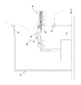
- FIG. 6 is a schematic view showing position relationship among the automatic bracket positioning device, head support and the patient's head, in accordance with the present disclosure.
- the automated orthodontic bracket positioning system 10 of the present disclosure includes a bite record device 2 , an automatic bracket positioning device 30 and a computer system 80 .
- the bite recorder 20 is coupled with the automatic bracket positioning device 30 and the computer system 80 .
- the computer system 80 is configured for constructing a digital 3D dental model, and the technology of building the digital 3D dental model 81 is a well-known technology, such as contact-type measurement technology, intra-oral scan technology, or chromatography, incorporating with software program computation and analysis, so as to acquire the orientation and coordinate data of the teeth of patient's upper and lower dentitions, and information of position relationship between the mandible and the maxilla.
- the computer system 80 estimates a predicted position of each orthodontic bracket on patient's tooth surface or a surface of the dental cast by using the digital 3D dental model.
- the computer system 80 controls the automatic bracket positioning device 30 to position the brackets 32 on the patient's tooth surfaces or the surfaces of the dental cast according to the predicted positions (please refer to FIG. 4 ).
- the bite record device 2 includes a bite recorder 20 and a sensor 24 for detecting the bite recorder 20 .
- the bite recorder 20 is a sturdy tray 21 in flat arc shape.
- the tray 21 is pre-coated with dental impression material 25 on both surfaces thereof.
- the tray 21 is placed into the patient's mouth to be lightly bitten by the patient's upper and lower dentitions, and the bite condition of the tooth can be recorded via the dental impression material 25 and the bite recorder 20 is steadily fastened on the dentition and hardly shifted in the patient's mouth, so as to ensure the subsequent detection to be precisely executed.
- the tray 21 is provided with calibrating markers 22 respectively disposed at multiple preset positions.
- a connector 23 is assembled at a front end of the tray 21 and extended outwardly.
- the connector 23 is not inserted into the patient's mouth.
- the connector 23 is connected with the automatic bracket positioning device 30 and the computer system 80 .
- the sensor 24 is disposed at a distal toggle 62 or a holder 31 of a multi-joint robotic arm 61 of the automatic bracket positioning device 30 , and configured for detecting the calibrating markers 22 which are used as intra-oral reference point in the patient's mouth.
- the sensor 24 detects the intra-oral reference points to generate multiple groups of digital point sets related to the space positions on tooth surfaces, and transmits the digital point sets to the computer system 80 via a transmission line (not shown in FIGs).
- the computer system executes a program computation to convert the digital point sets into an intra-oral coordinate record.
- the computer system receives and utilizes the intra-oral coordinate record to calibrate the digital 3D dental model, to ensure the practical intra-oral coordinate to match with the computation coordinate of the digital 3D dental model. Therefore, the predicted positions of the brackets estimated by the computer system can accurately match with the patient's tooth surfaces.
- the computer system acquires the information of position relationship between the sensors 24 and the calibrating markers 22 according to information collected by the sensors 24 , and then controls the multi-joint robotic arm 61 according to the acquired information until the bracket 32 is accurately transferred onto the tooth surface according to the predicted position.
- the automatic bracket positioning device 30 includes a holder 31 , a control module 41 , a light emitting module 51 and a multi-joint robotic arm 61 .
- the holder 31 is configured for holding or releasing a bracket 32 .
- the bracket 32 is an existing physical structure and includes a base 321 .
- a side of the base 321 is coated a layer of light-curing adhesive 322 , and the base 321 is provided with a body 323 at other side thereof.
- the body 323 is provided with a wire slot 324 at a center part thereof for receiving a metal wire, and provided with recessed parts 325 at two opposite sides thereof respectively for receiving the holder 31 .
- the holder 31 is provided with a first arm 33 and a second arm 34 , first ends of the first arm 33 and the second arm 34 are linked to a positioning plate 35 via a rotating pivot 331 and 341 , and second ends of the first arm 33 and the second arm 34 are provided with fastening members 332 and 342 which can fasten or release a recessed part 325 of the holder 31 .
- the first arm 33 and the second arm 34 are provided with first rods 333 and 343 and second rods 334 and 344 respectively.
- the first rods 333 and 343 , and the second rods 334 and 344 are linked and fastened with each other via an axis.
- the positioning plate 35 is linked and fastened with the distal toggle 62 of the multi-joint robotic arm 61 via a structural component 351 .
- the control module 41 includes an actuating rod 411 and an actuator 412 which is used for controlling the actuating rod 411 to reciprocate.
- the actuating rod 411 is inserted axially through the structural component 351 , a first end of the actuating rod 411 is passed through the end plate 621 of the distal toggle 62 and inserted into the distal toggle 62 , and an inner end of the actuating rod 411 is linked with a contact member 622 .
- a reset spring 623 is mounted on the actuating rod 411 between the contact member 622 and the end plate 621 .
- a second end of the actuating rod 411 is passed through the positioning plate 35 , and linked with first ends of a first support rod 354 and a second support rod 355 .
- the first support rod 354 and the second support rod 355 are linked with an axis 353 .
- a second end of the first support rod 354 is linked with an axis 335 of the first arm 33
- a second end of the second support rod 355 is linked with an axis 345 of the second arm 34 .
- the actuating rod 411 when the actuating rod 411 reciprocates along the axis of the structural component 351 , the linear motion of the actuating rod 411 is converted to the linkage motions of the first arm 33 and the second arm 34 via the first support rod 354 and the second support rod 355 , so that the fastening member 332 and 342 can be fastened with or released from a recessed part 325 of the bracket 32 . Accordingly, the holder 31 can hold or release the bracket 32 .
- the actuator 412 is disposed within the distal toggle 62 of the multi-joint robotic arm 61 and the actuator 412 can be a mechanical assembly or a magnetic assembly. As shown in FIGs, the actuator 412 is a magnetic assembly and coupled with the computer system 80 via a coil and a conductive wire.
- the computer system 80 directs, controls and commands the actuator 412 to exert a pushing force on the contact member 622 or relieve the pushing force for the contact member 622 .
- the actuating rod 411 is moved toward the holder 31 to compress the reset spring 623 to enable the holder 31 to release the bracket 32 .
- the contact member 622 is restored by the reset spring 623 to drive the actuating rod 411 to move in reverse, so that the holder 31 can be closed to nip the bracket 32 .
- the light emitting module 51 is disposed on the end plate 621 of the distal toggle 62 of the multi joint robotic arm 61 , and coupled with the computer system 80 .
- the computer system 80 directs, controls and commands the light emitting module 51 to turn on or off.
- the light emitting module 51 provides a curing light toward the light-curing adhesive 322 .
- the curing light is used to harden the light-curing adhesive 322 of the brackets 32 .
- the multi joint robotic arm 61 is directed, controlled and commanded by the computer system 80 to execute a multi-angle, multi-axle and multi-curvature movement, in cooperation with the linking operation of the holder 31 and the control module 41 , to pick up the brackets 32 from the bracket tray (not shown in FIGs) and place the brackets 32 on the patient's tooth surfaces according to the predicted positions estimated by the computer system 80 .
- the brackets 32 are prepared in the bracket tray, one by one, following the tooth sequence in four quarters, upper-left, upper-right, lower-left and lower-right regions. This is a well-known arrangement.
- the multi-joint robotic arm 61 is provided with a pressure sensor (not shown in FIGs).
- a pressure sensor detects the pressure reaching a predetermined value, it indicates that the bracket 32 is stably touched with the patient's tooth surface already.
- the computer system 80 activates the light emitting module 51 to irradiate curing light to harden the light-curing adhesive 322 , whereby the bracket 32 can be bolded on the patient's tooth surface.
- the computer system 80 commands the control module 41 to operate to enable the holder 31 to open, so that the holder 31 can be separated from the bracket 32 located on the patient's tooth surface.
- a head support 70 is used in the present disclosure, and the head support 70 includes a forehead guide 71 and a chin guide 72 .
- the forehead guide 71 is located above the automatic bracket positioning device 30
- the chin guide 72 is located below the automatic bracket positioning device 30
- the forehead guide 71 and the chin guide 72 are fastened in a base 73 .
- the patient's chin is held by the chin guide 72 and the patient's forehead is contacted with the forehead guide 71 , so as to keep the patient's head being at an upright status.
- the automatic bracket positioning device 30 places the brackets 32 on the patient's tooth surfaces one by one, and then the dentist engages metal wires on the brackets 32 .
- the metal wires interact with the brackets to move the teeth into the desired positions for a preset period of time.
Landscapes
- Health & Medical Sciences (AREA)
- Oral & Maxillofacial Surgery (AREA)
- Dentistry (AREA)
- Epidemiology (AREA)
- Life Sciences & Earth Sciences (AREA)
- Animal Behavior & Ethology (AREA)
- General Health & Medical Sciences (AREA)
- Public Health (AREA)
- Veterinary Medicine (AREA)
- Engineering & Computer Science (AREA)
- General Engineering & Computer Science (AREA)
- Dental Tools And Instruments Or Auxiliary Dental Instruments (AREA)
Applications Claiming Priority (3)
| Application Number | Priority Date | Filing Date | Title |
|---|---|---|---|
| CN201410316398.X | 2014-07-04 | ||
| CN201410316398.XA CN104083224B (zh) | 2014-07-04 | 2014-07-04 | 自动化口腔正畸托槽定位系统 |
| CN201410316398 | 2014-07-04 |
Publications (2)
| Publication Number | Publication Date |
|---|---|
| US20160000526A1 US20160000526A1 (en) | 2016-01-07 |
| US9855115B2 true US9855115B2 (en) | 2018-01-02 |
Family
ID=51631062
Family Applications (1)
| Application Number | Title | Priority Date | Filing Date |
|---|---|---|---|
| US14/789,667 Expired - Fee Related US9855115B2 (en) | 2014-07-04 | 2015-07-01 | Automated orthodontic bracket positioning system and method |
Country Status (5)
| Country | Link |
|---|---|
| US (1) | US9855115B2 (zh) |
| CN (1) | CN104083224B (zh) |
| GB (1) | GB2541628A (zh) |
| TW (1) | TWI549661B (zh) |
| WO (1) | WO2016000291A1 (zh) |
Cited By (2)
| Publication number | Priority date | Publication date | Assignee | Title |
|---|---|---|---|---|
| US20210275279A1 (en) * | 2018-10-09 | 2021-09-09 | Brandon Dale Kofford | Robotic assisted screw-attached pick-up dental coping systems and methods |
| US11166787B1 (en) | 2021-01-06 | 2021-11-09 | Arkimos Ltd | Orthodontic attachment systems and methods |
Families Citing this family (26)
| Publication number | Priority date | Publication date | Assignee | Title |
|---|---|---|---|---|
| US9222255B2 (en) * | 2013-08-01 | 2015-12-29 | Urbaneer LLC | Apparatus and method for reconfigurable space |
| CN104546157A (zh) * | 2015-01-28 | 2015-04-29 | 浙江隐齿丽医学技术有限公司 | 非人工加工牙套的工艺 |
| CN105662615B (zh) * | 2016-03-14 | 2018-03-23 | 赵计林 | 一种正畸托槽间接粘接精确定位系统及应用方法 |
| CN105852995B (zh) * | 2016-04-27 | 2018-08-07 | 叶年嵩 | 一种个性化舌侧托槽矫治器及其制作方法 |
| JP2019536561A (ja) * | 2016-11-30 | 2019-12-19 | ケアストリーム・デンタル・テクノロジー・トプコ・リミテッド | 歯列メッシュからのブレース除去のための方法およびシステム |
| CN108268673B (zh) * | 2016-12-30 | 2022-08-16 | 无锡时代天使医疗器械科技有限公司 | 用于对牙齿矫治器的矫治效果进行数字化仿真的方法 |
| US10405949B2 (en) * | 2017-05-04 | 2019-09-10 | Daniel Lee | Methods and devices for applying orthodontic brackets |
| US20190046297A1 (en) * | 2017-08-11 | 2019-02-14 | Align Technology, Inc. | Devices and systems for creation of attachments for use with dental appliances and changeable shaped attachments |
| DE102017127128A1 (de) | 2017-11-17 | 2019-05-23 | Gustav Gerstenkamp | Verfahren zum virtuellen Modellieren eines Zahnbogens |
| TWI644655B (zh) * | 2017-11-23 | 2018-12-21 | 勘德股份有限公司 | 數位齒模分割方法及數位齒模分割裝置 |
| US11049276B2 (en) | 2018-06-29 | 2021-06-29 | Industrial Technology Research Institute | Positioning guidance method and system for tooth brackets |
| CN108992192A (zh) * | 2018-08-22 | 2018-12-14 | 王宝兰 | 一种可调节式口腔科印模托盘装置 |
| CN111358583B (zh) * | 2018-12-26 | 2022-09-20 | 无锡时代天使医疗器械科技有限公司 | 壳状牙科器械附件安装系统及方法 |
| US10959817B2 (en) * | 2019-08-14 | 2021-03-30 | Sdc U.S. Smilepay Spv | Dental model holding system |
| CN113491532B (zh) * | 2020-03-20 | 2024-03-22 | 苏州佳世达光电有限公司 | 口扫机系统及口扫机的操作方法 |
| CN111513875B (zh) * | 2020-04-29 | 2021-10-08 | 西安交通大学口腔医院 | 一种简易口腔正畸间接粘连托槽转移装置 |
| CN111728722B (zh) * | 2020-06-23 | 2022-05-27 | 深圳市第二人民医院(深圳市转化医学研究院) | 一种托槽定位装置 |
| CN111956348B (zh) * | 2020-06-24 | 2021-11-02 | 深圳市美鸣齿科技术有限公司 | 义齿自动涂刷方法、系统、设备及存储介质 |
| CN111728723B (zh) * | 2020-07-27 | 2021-08-17 | 西安交通大学口腔医院 | 一种口腔正畸的托槽安装装置 |
| CN112336483B (zh) * | 2020-11-27 | 2022-04-05 | 广州德伦荔泰口腔门诊部有限公司 | 一种口腔科的针对正畸装置佩戴者的口腔清洁装置 |
| CN112656527B (zh) * | 2020-12-25 | 2021-09-14 | 首都医科大学附属北京口腔医院 | 一种口腔牙齿正畸托槽定位系统 |
| CN112932697B (zh) * | 2021-01-29 | 2022-05-24 | 正雅齿科科技(上海)有限公司 | 一种牙颌模型中硬腭区域识别方法及系统 |
| CN112908134A (zh) * | 2021-04-01 | 2021-06-04 | 西安交通大学医学院第一附属医院 | 一种医用口腔正畸训练装置 |
| CN114041894A (zh) * | 2021-11-16 | 2022-02-15 | 北京大学口腔医学院 | 牙科咬合记录装置的制作方法及牙科咬合记录装置 |
| CN113995534A (zh) * | 2021-11-18 | 2022-02-01 | 刘岚 | 一种制作牙合垫的方法 |
| CN116138905A (zh) * | 2023-03-07 | 2023-05-23 | 山东大学 | 一种机器人辅助正畸托槽粘结方法及粘接系统 |
Citations (10)
| Publication number | Priority date | Publication date | Assignee | Title |
|---|---|---|---|---|
| US4579380A (en) * | 1983-12-06 | 1986-04-01 | Carnegie-Mellon University | Servo robot gripper |
| US4850864A (en) * | 1987-03-30 | 1989-07-25 | Diamond Michael K | Bracket placing instrument |
| WO2001087179A1 (de) * | 2000-05-19 | 2001-11-22 | Albert Nadler | Vorrichtung und verfahren zum platzieren von zahnspangen-brackets auf zähnen |
| US20030204150A1 (en) * | 2002-04-25 | 2003-10-30 | Wolfgang Brunner | Method and apparatus for the 3-dimensional analysis of movement of the tooth surfaces of the maxilla in relation to the mandible |
| US20030215767A1 (en) | 2002-05-02 | 2003-11-20 | Eldad Taub | Appliance for positioning orthodontic components |
| US20060275736A1 (en) * | 2005-04-22 | 2006-12-07 | Orthoclear Holdings, Inc. | Computer aided orthodontic treatment planning |
| US20080253506A1 (en) * | 2005-05-04 | 2008-10-16 | Gerhard Zuendorf | Bone Density Calibration Method and System |
| CN102138829A (zh) | 2010-04-08 | 2011-08-03 | 沃尔夫冈·黑舍 | 带安装辅具的口腔正畸托安装结构 |
| CN102481181A (zh) | 2009-06-24 | 2012-05-30 | 科斯莫技术有限责任公司 | 颚操纵器 |
| US8366442B2 (en) * | 2006-02-15 | 2013-02-05 | Bankruptcy Estate Of Voxelogix Corporation | Dental apparatus for radiographic and non-radiographic imaging |
Family Cites Families (6)
| Publication number | Priority date | Publication date | Assignee | Title |
|---|---|---|---|---|
| US5879158A (en) * | 1997-05-20 | 1999-03-09 | Doyle; Walter A. | Orthodontic bracketing system and method therefor |
| JP4284690B2 (ja) * | 2006-05-18 | 2009-06-24 | 優 深山 | 下顎側方運動補助器具 |
| CN201260704Y (zh) * | 2008-10-06 | 2009-06-24 | 井庆泉 | 方丝弓矫治器托槽用镊子 |
| TW201121516A (en) * | 2009-12-31 | 2011-07-01 | zheng-he Huang | Structure and positioning method of dental bracket |
| CN102319124B (zh) * | 2011-09-26 | 2013-09-25 | 杭州六维齿科医疗技术有限公司 | 用于正畸托槽间接粘接的数字化导向模板 |
| TWM469884U (zh) * | 2013-07-19 | 2014-01-11 | Densmart Dental Co Ltd | 口腔矯正植體手術用定位測定裝置 |
-
2014
- 2014-07-04 CN CN201410316398.XA patent/CN104083224B/zh not_active Expired - Fee Related
- 2014-08-06 GB GB1622165.7A patent/GB2541628A/en not_active Withdrawn
- 2014-08-06 WO PCT/CN2014/083818 patent/WO2016000291A1/zh active Application Filing
- 2014-09-18 TW TW103132313A patent/TWI549661B/zh not_active IP Right Cessation
-
2015
- 2015-07-01 US US14/789,667 patent/US9855115B2/en not_active Expired - Fee Related
Patent Citations (10)
| Publication number | Priority date | Publication date | Assignee | Title |
|---|---|---|---|---|
| US4579380A (en) * | 1983-12-06 | 1986-04-01 | Carnegie-Mellon University | Servo robot gripper |
| US4850864A (en) * | 1987-03-30 | 1989-07-25 | Diamond Michael K | Bracket placing instrument |
| WO2001087179A1 (de) * | 2000-05-19 | 2001-11-22 | Albert Nadler | Vorrichtung und verfahren zum platzieren von zahnspangen-brackets auf zähnen |
| US20030204150A1 (en) * | 2002-04-25 | 2003-10-30 | Wolfgang Brunner | Method and apparatus for the 3-dimensional analysis of movement of the tooth surfaces of the maxilla in relation to the mandible |
| US20030215767A1 (en) | 2002-05-02 | 2003-11-20 | Eldad Taub | Appliance for positioning orthodontic components |
| US20060275736A1 (en) * | 2005-04-22 | 2006-12-07 | Orthoclear Holdings, Inc. | Computer aided orthodontic treatment planning |
| US20080253506A1 (en) * | 2005-05-04 | 2008-10-16 | Gerhard Zuendorf | Bone Density Calibration Method and System |
| US8366442B2 (en) * | 2006-02-15 | 2013-02-05 | Bankruptcy Estate Of Voxelogix Corporation | Dental apparatus for radiographic and non-radiographic imaging |
| CN102481181A (zh) | 2009-06-24 | 2012-05-30 | 科斯莫技术有限责任公司 | 颚操纵器 |
| CN102138829A (zh) | 2010-04-08 | 2011-08-03 | 沃尔夫冈·黑舍 | 带安装辅具的口腔正畸托安装结构 |
Non-Patent Citations (2)
| Title |
|---|
| Ganz, Scott D; Inside Dentistry. "The Next Evolution in CBCT: Combining Digital Technologies." vol. 9, Issue 2; Feb. 2013. * |
| Zhao Meng et al, "Model Measurement and Bracker Position System in Digital Three-Dimensional Dental Cast", Mar. 2008, Medical Information vol. 21. No. 3, pp. 1-4. |
Cited By (3)
| Publication number | Priority date | Publication date | Assignee | Title |
|---|---|---|---|---|
| US20210275279A1 (en) * | 2018-10-09 | 2021-09-09 | Brandon Dale Kofford | Robotic assisted screw-attached pick-up dental coping systems and methods |
| US11166787B1 (en) | 2021-01-06 | 2021-11-09 | Arkimos Ltd | Orthodontic attachment systems and methods |
| US11564776B2 (en) | 2021-01-06 | 2023-01-31 | Arkimos Ltd | Orthodontic attachment systems and methods |
Also Published As
| Publication number | Publication date |
|---|---|
| US20160000526A1 (en) | 2016-01-07 |
| CN104083224B (zh) | 2017-04-05 |
| GB201622165D0 (en) | 2017-02-08 |
| TW201601689A (zh) | 2016-01-16 |
| TWI549661B (zh) | 2016-09-21 |
| GB2541628A (en) | 2017-02-22 |
| WO2016000291A1 (zh) | 2016-01-07 |
| CN104083224A (zh) | 2014-10-08 |
Similar Documents
| Publication | Publication Date | Title |
|---|---|---|
| US9855115B2 (en) | Automated orthodontic bracket positioning system and method | |
| JP6886918B2 (ja) | 歯科用装置のコンピュータシステム支援設計 | |
| JP4230667B2 (ja) | 歯列矯正器具を正確に結合配置する方法および装置 | |
| JP6601775B2 (ja) | 歯列矯正装置の製造設備 | |
| JP4406006B2 (ja) | 歯科矯正器具のインダイレクトボンディング法および装置 | |
| JP5475473B2 (ja) | 歯科矯正治療用のインダイレクトボンディングトレー及びその製造方法 | |
| AU2006232959B2 (en) | Orthodontic indirect bonding apparatus with occlusal positioning stop members | |
| JP5341779B2 (ja) | 光硬化性接着材料を使用して歯列矯正装具を接着するための方法及び装置 | |
| JP2016501592A (ja) | 歯科スキャナ装置 | |
| EP3111886B1 (en) | Tool for obtaining dental occlusion in patient with edentulous jaw | |
| US11576767B2 (en) | Device and method for measuring a movement of a mandible | |
| KR101869907B1 (ko) | 디지털 라이브러리를 이용한 치아교정용 디지털 브라켓의 제조방법 | |
| JP5891080B2 (ja) | 顎運動シミュレーション方法、顎運動シミュレーション装置、及び顎運動シミュレーションシステム | |
| CN106456305A (zh) | 一种颌位关系记录方法及装置 | |
| KR101913834B1 (ko) | 디지털 치열교정 시스템 | |
| US8757875B2 (en) | Sensor positioning and stabilizing device | |
| KR101883943B1 (ko) | 치아교정용 디지털 브라켓 | |
| KR101862820B1 (ko) | 틀니 제조방법 | |
| JP2001029364A (ja) | 顎運動装置 | |
| WO2018147157A1 (ja) | 採得器具 | |
| US20230092457A1 (en) | Device for Simulating Lower Jaw Activity | |
| Mostashiri et al. | A Low-Cost Simple Method for Capturing the Mandibular Motion | |
| KR101628607B1 (ko) | 로봇암 적용 교합기 및 그의 교합 방법 | |
| CA2862432A1 (en) | Sensor positioning and stabilizing device |
Legal Events
| Date | Code | Title | Description |
|---|---|---|---|
| AS | Assignment |
Owner name: TAM WENG KIE, HONG KONG Free format text: ASSIGNMENT OF ASSIGNORS INTEREST;ASSIGNORS:TAM, WENG KONG;TAM, WENG KIE;SIGNING DATES FROM 20150622 TO 20150623;REEL/FRAME:036134/0633 |
|
| AS | Assignment |
Owner name: TAM, WENG-KIE, HONG KONG Free format text: ASSIGNMENT OF ASSIGNORS INTEREST;ASSIGNORS:TAM, WENG KONG;TAM, WENG KIE;SIGNING DATES FROM 20150622 TO 20150623;REEL/FRAME:036468/0830 |
|
| STCF | Information on status: patent grant |
Free format text: PATENTED CASE |
|
| FEPP | Fee payment procedure |
Free format text: MAINTENANCE FEE REMINDER MAILED (ORIGINAL EVENT CODE: REM.); ENTITY STATUS OF PATENT OWNER: SMALL ENTITY |
|
| LAPS | Lapse for failure to pay maintenance fees |
Free format text: PATENT EXPIRED FOR FAILURE TO PAY MAINTENANCE FEES (ORIGINAL EVENT CODE: EXP.); ENTITY STATUS OF PATENT OWNER: SMALL ENTITY |
|
| STCH | Information on status: patent discontinuation |
Free format text: PATENT EXPIRED DUE TO NONPAYMENT OF MAINTENANCE FEES UNDER 37 CFR 1.362 |
|
| FP | Lapsed due to failure to pay maintenance fee |
Effective date: 20220102 |