US9732397B2 - Defective engine block recycling method in continuous casting line - Google Patents
Defective engine block recycling method in continuous casting line Download PDFInfo
- Publication number
- US9732397B2 US9732397B2 US14/830,370 US201514830370A US9732397B2 US 9732397 B2 US9732397 B2 US 9732397B2 US 201514830370 A US201514830370 A US 201514830370A US 9732397 B2 US9732397 B2 US 9732397B2
- Authority
- US
- United States
- Prior art keywords
- engine block
- aluminum
- liner
- defective
- mold
- Prior art date
- Legal status (The legal status is an assumption and is not a legal conclusion. Google has not performed a legal analysis and makes no representation as to the accuracy of the status listed.)
- Expired - Fee Related
Links
Images


Classifications
-
- C—CHEMISTRY; METALLURGY
- C22—METALLURGY; FERROUS OR NON-FERROUS ALLOYS; TREATMENT OF ALLOYS OR NON-FERROUS METALS
- C22B—PRODUCTION AND REFINING OF METALS; PRETREATMENT OF RAW MATERIALS
- C22B7/00—Working up raw materials other than ores, e.g. scrap, to produce non-ferrous metals and compounds thereof; Methods of a general interest or applied to the winning of more than two metals
- C22B7/001—Dry processes
- C22B7/003—Dry processes only remelting, e.g. of chips, borings, turnings; apparatus used therefor
-
- B—PERFORMING OPERATIONS; TRANSPORTING
- B22—CASTING; POWDER METALLURGY
- B22D—CASTING OF METALS; CASTING OF OTHER SUBSTANCES BY THE SAME PROCESSES OR DEVICES
- B22D19/00—Casting in, on, or around objects which form part of the product
- B22D19/0009—Cylinders, pistons
-
- Y—GENERAL TAGGING OF NEW TECHNOLOGICAL DEVELOPMENTS; GENERAL TAGGING OF CROSS-SECTIONAL TECHNOLOGIES SPANNING OVER SEVERAL SECTIONS OF THE IPC; TECHNICAL SUBJECTS COVERED BY FORMER USPC CROSS-REFERENCE ART COLLECTIONS [XRACs] AND DIGESTS
- Y02—TECHNOLOGIES OR APPLICATIONS FOR MITIGATION OR ADAPTATION AGAINST CLIMATE CHANGE
- Y02P—CLIMATE CHANGE MITIGATION TECHNOLOGIES IN THE PRODUCTION OR PROCESSING OF GOODS
- Y02P10/00—Technologies related to metal processing
- Y02P10/20—Recycling
-
- Y02P10/218—
Definitions
- the present invention relates to a defective engine block recycling method in a continuous casting line. More particularly, the present invention pertains to a defective engine block recycling method in a continuous casting line in which, if a defect is expected to generate in a process of continuously casting engine blocks for use in motor vehicles, ships, aircrafts and the like, an engine block is cast using an aluminum-made dummy liner instead of a cast iron liner. The defective engine block thus manufactured is immediately recycled into an aluminum ingot. This eliminates the need to perform a work of removing a cast iron liner from an aluminum engine block, thereby reducing the cost and improving the quality of a recycled aluminum ingot.
- engine blocks for use in motor vehicles, ships, air crafts and the like are often manufactured using lightweight aluminum instead of cast iron.
- an aluminum engine block is high-priced but is advantageous in that it is possible to significantly reduce the weight of the engine block.
- An aluminum engine block is usually manufactured by a die casting method.
- the die casting method is a casting method used in casting nonferrous metal.
- molten metal is injected into a die at a pressure equal to or higher than the atmosphere pressure and is continuously pressed by a plunger until the molten metal is completely solidified.
- the die casting method has been used in casting metal types. Along with the development of nonferrous metal having high, strength, the range of application of the die casting method is gradually widened.
- a mold employed in the die casting method suddenly makes contact with a high-temperature molten metal.
- corrosions or cracks are easily generated on the surface of the mold.
- special steel having a high heat resistance is primarily used in making a die-casting-purpose mold.
- the die casting machine In order to perform a die casting process, it is necessary to use a die casting machine for pressurizing and injecting molten metal.
- the die casting machine is designed to inject molten metal into a mold at a high pressure and a high speed using a compressed air or a hydraulic plunger.
- the die casting method is more costly than an ordinary casting method and is not suitable for production of a small number of articles.
- the die casting method is economical only when mass-producing the same kind of products.
- die casting machines may be classified into a hot-chamber-type die casting machine and a cold-chamber-type die casting machine.
- a pressurizing cylinder is disposed within a melting pot.
- a plunger is moved into the pressurizing cylinder by a pneumatic pressure, a hydraulic pressure or an oil pressure, thereby pushing molten metal into a mold.
- Aluminum engine blocks are primarily manufactured by the hot-chamber-type die casting machine.
- a constant temperature e.g., 250 to 300 degrees C.
- a melting furnace is independently provided in the cold-chamber-type die casting machine.
- Molten metal is taken out of the melting furnace and is put into a pressurizing chamber.
- the molten metal is pushed into a die by a plunger. That is to say, in the cold-chamber-type die casting machine, molten metal is put into a sleeve made of special steel.
- molten metal is injected into a die with a plunger mounted to the front end of the piston rod.
- the cold-chamber-type die casting machine has an advantage in that impurities are less likely to infiltrate into the molten metal and a dense structure can be obtained by applying a high pressure at an initial cooling stage and during a solidifying period.
- die casting machines may be divided into a vertical die casting machine and a horizontal die casting machine.
- a movable die In the vertical die casting machine, a movable die is vertically disposed on a fixed die. In the horizontal die casting machine, a fixed die and a movable die are horizontally disposed. While the vertical die casting machine has been extensively used in the past, the horizontal die casting machine is predominantly used in recent years.
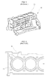
- FIGS. 1 and 2 illustrate one example of an aluminum engine block 10 manufactured by the aforementioned die casting method.
- the aluminum engine block 10 includes a body made of aluminum and a cast iron liner 20 having a superior wear resistance.
- reference numeral 30 designates a water jacket for cooling an engine.
- An aluminum engine block 10 is automatically manufactured by a die casting machine in an ordinary continuous casting line.
- an engine block mold M is mounted to a die.
- a bore pin 40 is fitted to the engine block mold M.
- the bore pin 40 which serves as a core during a casting process, is configured to support a cast iron liner 20 when pressurizing molten aluminum.
- the cast iron liner 20 is fitted to the outer circumferential surface of the bore pin 40 using a robot arm 50 .
- the cast iron liner 20 is formed in a cylindrical shape so as to have a predetermined thickness.
- the inner circumferential surface of the cast iron liner 20 is machined.
- a plurality of cast iron liners 20 is disposed side by side along a casting line.
- the robot arm 50 picks up four cast iron liners 20 and fits the cast iron liners 20 to the outer circumferential surfaces of bore pins 40 .
- the defective engine block is discarded or recycled. In the case of discarding the defective engine block, a loss of material cost grows larger. In the case of recycling the defective engine block, a large amount of cost is incurred in the recycling process.
- the defective engine block is melted and recycled into an aluminum ingot without completely removing a cast iron component, the quality of the aluminum ingot is reduced due to the cast iron component remaining in the aluminum ingot.
- it is thinkable to remove a cast iron component from molten aluminum. In this case, however, a large amount of cost is incurred.
- Korean Patent Application Publication No. 10-2006-0131064 discloses a method of detaching and recovering a cylinder liner from a cylinder block.
- a cylinder block for an automotive engine to be recycled is loaded onto a conveyer.
- the inner surface of a cylinder liner is heated by flames or induction heating.
- a boundary region between an aluminum body and a cylinder liner of the cylinder block is heated to a temperature equal to or higher than a melting point of the aluminum body, thereby removing the cylinder liner.
- Korean Patent No. 10-0625109 discloses an apparatus and method of removing a liner from an aluminum cylinder block.
- a defective product generated in a cylinder block manufacturing process is recycled into a raw material for the production of a cylinder block without going through an additional smelting process.
- the apparatus for manufacturing a cylinder block including a cylinder body made of aluminum and a liner made of another metallic material and fixed to the inner surface of the cylinder body includes a bed, a movable base installed so as to reciprocate toward and away the bed, a fixing means for fixing a detective cylinder block to one of the bed and the movable base, a cutting tool mounted to the other of the bed and the movable base at the opposite side of the cylinder block in a position corresponding to the cylinder of the cylinder block, the cutting tool having a cutting diameter larger than the outer diameter of the liner, a rotating means for rotating the cutting tool, and a moving means for moving the movable bas toward the bed so that the liner of the cylinder block and the peripheral portion thereof are cut by the cutting tool.
- the apparatus of the prior art cited above is designed to remove the cylinder liner through a cutting work in the case where defects are generated in the cylinder block.
- the apparatus of the prior art is extremely complex due to the provision of the additional cutting tool.
- Another object of the present invention is to provide a defective engine block recycling method in a continuous casting line, which is capable of easily recycling a defective engine block unit without resort to an additional recycling facility or work and significantly reducing a recycling cost.
- a further object of the present invention is to provide a defective engine block recycling method in a continuous casting line, which is capable of preventing stoppage of an operation of the continuous casting line by, if a defect is expected to generate in an engine block body, mounting a dummy liner rather than a real liner to a mold so that a casing process is continuously performed without stoppage.
- a still further object of the present invention is to provide a defective engine block recycling method in a continuous casting line, which is capable of directly melting and recycling a defective engine block unit without going through an additional work by using a dummy liner made of a material identical with or similar to a material of an engine block body.
- a yet still further object of the present invention is to provide a defective engine block recycling method in a continuous casting line, which is capable of reliably preventing inclusion of a cast iron component in a defective engine block unit, thereby preventing deterioration of physical properties of a recycled aluminum ingot otherwise caused by the mixture of impurities and improving the quality of a recycled aluminum ingot.
- a defective engine block recycling method in a continuous casting line including: inserting a bore pin into an engine block mold; fitting a real liner to an outer circumferential surface of the bore pin; and injecting molten aluminum into the engine block mold to cast an engine block body, wherein if an abnormality is generated in the engine block mold or the molten aluminum and if a defect is expected to generate in the engine block body, a defective engine block unit is produced by fitting a dummy liner, which is made of a material identical with or similar to a material of the engine block body, to the bore pin, and the defective engine block unit thus produced is directly melted and recycled.
- the engine block body may be made of aluminum
- the real liner may be made of cast iron
- the dummy liner may be made of a material which does not affect a quality of an aluminum ingot obtained by melting the defective engine block unit.
- the dummy liner may be melted and recycled without going through a process of removing the dummy liner from the defective engine block unit.
- the dummy liner may have a diameter which grows larger upward.
- the dummy liner may be formed by expanding or contracting an aluminum pipe.
- the defective engine block unit may be produced by a die casting machine.
- the die casting machine may include a temperature sensor configured to detect a temperature of the engine block mold and an alarming device configured to issue an alarm when the temperature of the engine block mold falls outside a predetermined temperature range.
- a defective engine block recycling method in a continuous casting line, which is capable of easily recycling a defective engine block unit in a cost-effective manner and minimizing a loss of material cost attributable to generation of a defect.
- FIG. 1 is a perspective view of an aluminum engine block manufactured by the prior art.
- FIG. 2 is a plan view of the aluminum, engine block illustrated in FIG. 1 .
- FIGS. 3A to 3D are sectional views illustrating how to mount a cast iron liner to a mold in the prior art.
- FIG. 4 is an enlarged sectional view illustrating how to fit a cast iron liner to a bore pin in the prior art.
- FIG. 5 is an enlarged sectional view illustrating how to fit a dummy liner to a bore pin according to the present invention.
- FIG. 6 is a flowchart illustrating a process of producing an engine block unit according to the present invention.
- FIGS. 5 and 6 One preferred embodiment of a defective engine block recycling method in a continuous casting line according to the present invention will now be described with reference to FIGS. 5 and 6 .
- a defective engine block recycling method in a continuous casting line includes; inserting a bore pin 40 into an engine block mold M; fitting a real liner 20 to an outer circumferential surface of the bore pin 40 ; and injecting molten aluminum into the engine block mold M to cast an engine block body 10 .
- a defective engine block unit is produced by fitting a dummy liner 20 a , which is made of a material identical with or similar to a material of the engine block body 10 , to the bore pin 40 , and the defective engine block unit thus produced is directly melted and recycled.
- the dummy liner 20 a is melted together with the defective engine block unit without removing the dummy liner 20 a from the defective engine block unit and is recycled into an aluminum ingot.
- the dummy liner 20 a is not used as a real cylinder liner. In the case where a defect is expected to generate in the engine block body 10 , the dummy liner 20 a is used in place of the cast iron real liner 20 in order to avoid stoppage of an operation in a continuous casting line.
- a defective engine block unit is recycled by breaking and removing a cast iron liner from an engine block body, or melting and removing a cast iron liner from an engine block body, or cutting and removing a cast iron liner from an engine block body using a cutting device. For that reason, a great deal of time and cost is required in recycling the defective engine block unit.
- the dummy liner 20 a is made of a material identical with or similar to a material of the engine block body 10 , specifically a material which does not reduce the quality of an aluminum ingot obtained by melting a defective engine block unit. Thus, there is no need to stop a continuous casting line even when a defect is expected to generate in the engine block body 10 .
- the dummy liner 20 a has a diameter which grows larger upward.
- the dummy liner 20 a is preferably formed by expanding or contracting an aluminum pipe produced through an extruding process.
- the method of manufacturing the dummy liner 20 a is not limited thereto.
- the engine block body 10 is cast by a die casting machine (not illustrated).
- the die casting machine preferably includes a temperature sensor configured to detect a temperature of the engine block mold M and an alarming device configured to issue an alarm when the temperature of the engine block mold M fails outside a predetermined temperature range.
- a worker may use the aluminum-made dummy liner 20 a instead of the cast iron real liner 20 .
- the defective engine block unit may be directly recycled by melting the dummy liner 20 a together with the engine block body 10 .
- the engine block mold M is mounted to the die casting machine, and the bore pin 40 is inserted into the engine block mold M.
- the cast iron real liner 20 and the dummy liner 20 a are disposed side by side on the continuous casting line. This enables a robot arm 50 , which will be described later, to selectively pick up the cast iron real liner 20 or the dummy liner 20 a and fit the same to the bore pin 40 .
- the bore pin 40 is a member which serves as a core in the casting process.
- the bore pin 40 is configured to support the cast iron liner 20 when injecting the molten aluminum into the engine block mold M.
- the robot arm 50 is operated so as to pick up the cast iron real liner 20 or the aluminum-made dummy liner 20 a and fit the same to the bore pin 40 .
- the robot arm 50 picks up four cast iron liners 20 or four dummy liners 20 a at a time and fits the same to the bore pin 40 .
- a defect may be generated in a specific section. Particularly, if molten aluminum is injected toward a cast iron real liner, a casting defect is often generated in a boundary region between the molten aluminum and the cast iron real liner.
- the temperature of the engine block mold M may fail, outside a suitable temperature range.
- the temperature sensor (not illustrated) of the die casting machine detects the temperature of the engine block mold M which fails outside the suitable temperature range. Then, the alarming device notifies a worker of the situation by issuing an alarm. Furthermore, there may be a case where the state of molten aluminum is poor and a defect is expected to generate in the engine block body 10 .
- the worker does not stop the continuous casting line but takes a measure so that the robot arm 50 picks up the dummy liner 20 a in place of the cast iron real liner 20 and fits the dummy liner 20 a to the bore pin 40 of the engine block mold M.
- the east iron real liner 20 is fitted to the bore pin 40 of the engine block mold M. If an abnormality is detected in the continuous casting line, the dummy liner 20 a is fitted to the bore pin 40 of the engine block mold M.
- the dummy liner 20 a is not used as a real cylinder liner because the dummy liner 20 a made of aluminum is weak in wear resistance and is unsuitable for use as a real cylinder liner.
- the dummy liner 20 a is used to manufacture a defective engine block unit without stopping the continuous casting line even in the case where a defect is expected to generate in the engine block body 10 .
- the continuous casting line may be continuously operated even when a defect is generated in an engine block body.
- a defect is generated in an engine block body.
- a cast iron real liner is integrally formed with an aluminum engine block body.
- a great deal of time and cost is required in recycling the defective product.
- the aluminum-made dummy liner 20 a is used in place of the cast iron real liner 20 . This makes it possible to continuously perform a casting work in the continuous casting line.
- the engine block body 10 and the dummy liner 20 a are made of an identical or similar material, it is possible to directly melt the defective engine block unit and to recycle the defective engine block unit into an aluminum ingot.
- the engine block body 10 and the dummy liner 20 a are made of an identical or similar material, it is possible to prevent deterioration of physical properties of a recycled aluminum ingot otherwise caused by the mixture of impurities and to improve the quality of a recycled aluminum ingot.
Landscapes
- Engineering & Computer Science (AREA)
- Mechanical Engineering (AREA)
- Chemical & Material Sciences (AREA)
- Geology (AREA)
- Life Sciences & Earth Sciences (AREA)
- Manufacturing & Machinery (AREA)
- General Life Sciences & Earth Sciences (AREA)
- Materials Engineering (AREA)
- Environmental & Geological Engineering (AREA)
- Metallurgy (AREA)
- Organic Chemistry (AREA)
- Molds, Cores, And Manufacturing Methods Thereof (AREA)
- Cylinder Crankcases Of Internal Combustion Engines (AREA)
Applications Claiming Priority (2)
| Application Number | Priority Date | Filing Date | Title |
|---|---|---|---|
| KR1020150080015A KR101685374B1 (ko) | 2015-06-05 | 2015-06-05 | 연속 주조 라인에서의 불량 엔진블록 재활용 방법 |
| KR10-2015-0080015 | 2015-06-05 |
Publications (2)
| Publication Number | Publication Date |
|---|---|
| US20160354837A1 US20160354837A1 (en) | 2016-12-08 |
| US9732397B2 true US9732397B2 (en) | 2017-08-15 |
Family
ID=57451469
Family Applications (1)
| Application Number | Title | Priority Date | Filing Date |
|---|---|---|---|
| US14/830,370 Expired - Fee Related US9732397B2 (en) | 2015-06-05 | 2015-08-19 | Defective engine block recycling method in continuous casting line |
Country Status (4)
| Country | Link |
|---|---|
| US (1) | US9732397B2 (es) |
| KR (1) | KR101685374B1 (es) |
| CN (1) | CN106238698B (es) |
| MX (1) | MX367693B (es) |
Citations (3)
| Publication number | Priority date | Publication date | Assignee | Title |
|---|---|---|---|---|
| US20060108089A1 (en) * | 2003-07-07 | 2006-05-25 | Mitsubishi Jidosha Kogyo Kabushiki Kaisha | Structure of cylinder block being cast with cylinder liner, method of manufacturing cylinder block, and cylinder liner to be cast in the method of manufacturing cylinder block |
| KR100625109B1 (ko) | 2005-06-29 | 2006-09-15 | 주식회사 유진소재산업 | 알루미늄 실린더블록의 라이너 제거 장치 및 방법 |
| KR20060131064A (ko) | 2005-06-15 | 2006-12-20 | 아강테크(주) | 실린더블록의 실린더 라이너 분리, 회수 방법 |
Family Cites Families (8)
| Publication number | Priority date | Publication date | Assignee | Title |
|---|---|---|---|---|
| DE4244502C1 (de) * | 1992-12-30 | 1994-03-17 | Bruehl Aluminiumtechnik | Zylinderkurbelgehäuse und Verfahren zu seiner Herstellung |
| KR20030016696A (ko) * | 2001-08-21 | 2003-03-03 | 현대자동차주식회사 | 엔진용 실린더 블록 제조방법 |
| KR100427281B1 (ko) * | 2001-09-05 | 2004-04-14 | 현대자동차주식회사 | 엔진용 실린더 블록 제조방법 |
| KR20060039698A (ko) * | 2004-11-03 | 2006-05-09 | 현대자동차주식회사 | 사탕용 실린더 라이너 제조장치 |
| US7921901B2 (en) * | 2008-04-16 | 2011-04-12 | GM Global Technology Operations LLC | Sacrificial sleeves for die casting aluminum alloys |
| CN202087810U (zh) * | 2011-06-07 | 2011-12-28 | 徐州徐航压铸有限公司 | 四缸发动机缸体压铸模的缸套柱结构 |
| CN102328202A (zh) * | 2011-09-29 | 2012-01-25 | 东风本田汽车有限公司 | 铝合金发动机废缸体回收再利用的方法及其冷式去除缸套设备 |
| CN203830698U (zh) * | 2014-05-28 | 2014-09-17 | 宁波市佳利来机械制造有限公司 | 发动机缸体压铸成型模具 |
-
2015
- 2015-06-05 KR KR1020150080015A patent/KR101685374B1/ko not_active Expired - Fee Related
- 2015-08-19 US US14/830,370 patent/US9732397B2/en not_active Expired - Fee Related
- 2015-09-14 CN CN201510582653.XA patent/CN106238698B/zh not_active Expired - Fee Related
-
2016
- 2016-06-03 MX MX2016007277A patent/MX367693B/es active IP Right Grant
Patent Citations (3)
| Publication number | Priority date | Publication date | Assignee | Title |
|---|---|---|---|---|
| US20060108089A1 (en) * | 2003-07-07 | 2006-05-25 | Mitsubishi Jidosha Kogyo Kabushiki Kaisha | Structure of cylinder block being cast with cylinder liner, method of manufacturing cylinder block, and cylinder liner to be cast in the method of manufacturing cylinder block |
| KR20060131064A (ko) | 2005-06-15 | 2006-12-20 | 아강테크(주) | 실린더블록의 실린더 라이너 분리, 회수 방법 |
| KR100625109B1 (ko) | 2005-06-29 | 2006-09-15 | 주식회사 유진소재산업 | 알루미늄 실린더블록의 라이너 제거 장치 및 방법 |
Non-Patent Citations (1)
| Title |
|---|
| Merriam-Webster definition of if, https://www.merriam-webster.com/dictionary/if, accessed Dec. 9, 2016. * |
Also Published As
| Publication number | Publication date |
|---|---|
| MX2016007277A (es) | 2016-12-05 |
| CN106238698A (zh) | 2016-12-21 |
| MX367693B (es) | 2019-09-02 |
| KR101685374B1 (ko) | 2016-12-13 |
| US20160354837A1 (en) | 2016-12-08 |
| CN106238698B (zh) | 2019-07-23 |
Similar Documents
| Publication | Publication Date | Title |
|---|---|---|
| JP2013099794A (ja) | 熱間鍛造による鍛造方法 | |
| US20170036269A1 (en) | Die casting machine shot sleeve | |
| JP2007260778A (ja) | 熱間鍛造装置、鍛造製品製造方法および鍛造製品 | |
| US10201850B2 (en) | Local extrusion device for high-pressure casting | |
| CN107824938A (zh) | 汽车冷冲模刃口堆焊方法 | |
| US9732397B2 (en) | Defective engine block recycling method in continuous casting line | |
| KR101971862B1 (ko) | 고진공 다이캐스팅 고압 공정을 이용한 다이캐스팅 금형의 진공배기 시스템 | |
| JP5035086B2 (ja) | 粗材冷却装置および方法 | |
| JP2002339794A (ja) | エンジンのシリンダブロック及びその製造方法 | |
| CN104607881A (zh) | 一种低温下防裂新型阀体的锻造工艺 | |
| KR101820812B1 (ko) | 폭발확관을 이용한 다이스캐스팅 금형의 냉각채널 이종접합방법 | |
| KR102763519B1 (ko) | 정밀 사형 주조용 용탕 누출 검지 장치 및 방법 | |
| KR102200915B1 (ko) | 다이 캐스팅용 슬리브의 내경 육성 용접 방법 | |
| KR101646358B1 (ko) | 다이캐스팅 방법 | |
| KR102553400B1 (ko) | 레이저헤드모듈을 이용한 비철금속 주조 레이저 절단방법 | |
| JP6373303B2 (ja) | 連続鋳造鋳型の補修方法 | |
| KR20150070735A (ko) | 센터 게이트형 다이캐스트 금형장치 및 이를 이용한 축대칭 방사형 제품의 제조방법 | |
| JP6379894B2 (ja) | 竪型鋳造機の竪型締装置及び型締制御方法 | |
| KR101341122B1 (ko) | 금속링 제조장치 및 방법 | |
| KR102910698B1 (ko) | 착탈식 멘드렐 및 다이스를 갖는 단동식 압출 성형 장치 | |
| KR102540789B1 (ko) | 다이캐스팅 공법을 이용한 차량용 부품 제조방법 | |
| US6923246B2 (en) | Billet, horizontal continuous casting process, and thixocasting process | |
| CN109433938B (zh) | 一种汽车模具快速加工工艺 | |
| CN105215313A (zh) | 一种用于制造辊颈的立式离心铸造装置 | |
| JP6256093B2 (ja) | 竪鋳込型ダイカストマシンの射出スリーブ温度制御方法 |
Legal Events
| Date | Code | Title | Description |
|---|---|---|---|
| AS | Assignment |
Owner name: AJU STEEL CO., LTD, KOREA, REPUBLIC OF Free format text: ASSIGNMENT OF ASSIGNORS INTEREST;ASSIGNOR:LEE, HAK YEON;REEL/FRAME:036364/0376 Effective date: 20150715 |
|
| STCF | Information on status: patent grant |
Free format text: PATENTED CASE |
|
| MAFP | Maintenance fee payment |
Free format text: PAYMENT OF MAINTENANCE FEE, 4TH YR, SMALL ENTITY (ORIGINAL EVENT CODE: M2551); ENTITY STATUS OF PATENT OWNER: SMALL ENTITY Year of fee payment: 4 |
|
| FEPP | Fee payment procedure |
Free format text: MAINTENANCE FEE REMINDER MAILED (ORIGINAL EVENT CODE: REM.); ENTITY STATUS OF PATENT OWNER: SMALL ENTITY |
|
| LAPS | Lapse for failure to pay maintenance fees |
Free format text: PATENT EXPIRED FOR FAILURE TO PAY MAINTENANCE FEES (ORIGINAL EVENT CODE: EXP.); ENTITY STATUS OF PATENT OWNER: SMALL ENTITY |
|
| STCH | Information on status: patent discontinuation |
Free format text: PATENT EXPIRED DUE TO NONPAYMENT OF MAINTENANCE FEES UNDER 37 CFR 1.362 |
|
| FP | Lapsed due to failure to pay maintenance fee |
Effective date: 20250815 |