US9677757B2 - Automatic water-adding vaporization pot - Google Patents
Automatic water-adding vaporization pot Download PDFInfo
- Publication number
- US9677757B2 US9677757B2 US14/422,659 US201314422659A US9677757B2 US 9677757 B2 US9677757 B2 US 9677757B2 US 201314422659 A US201314422659 A US 201314422659A US 9677757 B2 US9677757 B2 US 9677757B2
- Authority
- US
- United States
- Prior art keywords
- acquisition board
- temperature acquisition
- temperature
- pot body
- pot
- Prior art date
- Legal status (The legal status is an assumption and is not a legal conclusion. Google has not performed a legal analysis and makes no representation as to the accuracy of the status listed.)
- Expired - Fee Related, expires
Links
Images


Classifications
-
- F—MECHANICAL ENGINEERING; LIGHTING; HEATING; WEAPONS; BLASTING
- F22—STEAM GENERATION
- F22B—METHODS OF STEAM GENERATION; STEAM BOILERS
- F22B1/00—Methods of steam generation characterised by form of heating method
- F22B1/28—Methods of steam generation characterised by form of heating method in boilers heated electrically
- F22B1/284—Methods of steam generation characterised by form of heating method in boilers heated electrically with water in reservoirs
- F22B1/285—Methods of steam generation characterised by form of heating method in boilers heated electrically with water in reservoirs the water being fed by a pump to the reservoirs
-
- F—MECHANICAL ENGINEERING; LIGHTING; HEATING; WEAPONS; BLASTING
- F22—STEAM GENERATION
- F22D—PREHEATING, OR ACCUMULATING PREHEATED, FEED-WATER FOR STEAM GENERATION; FEED-WATER SUPPLY FOR STEAM GENERATION; CONTROLLING WATER LEVEL FOR STEAM GENERATION; AUXILIARY DEVICES FOR PROMOTING WATER CIRCULATION WITHIN STEAM BOILERS
- F22D5/00—Controlling water feed or water level; Automatic water feeding or water-level regulators
- F22D5/26—Automatic feed-control systems
Definitions
- the present disclosure relates to a vaporization pot, and more particularly to an automatic water-adding vaporization pot.
- a running time of the water pump is depended on a heat transfer rate and a heat capacity of the first temperature acquisition board.
- the heat transfer rate and the heat capacity of the first temperature acquisition board are depended on a mounting position, a volume and a shape of the first temperature acquisition board.
- the heating component is provided with a heating tube, and the one end of the first temperature acquisition board is located at the heating tube.
- the first temperature acquisition board and the heating component are connected together by welding or bolt connection.
- an on-off switch is connected into a power supply circuit of the heating component, and the on-off switch and the water-shortage and temperature sensing element are linked, or the water-shortage and temperature sensing element controls the on-off switch on or off.
- a reinforcing column is disposed within the pot body and has one end connected with an inner surface of a bottom of the pot body and the other end connected with a top of the pot body.
- a protection circuit for dry burning prevention comprises a PTC thermal protector for sensing a dry burning temperature, and the PTC thermal protector is connected with a heating control circuit of the heating component.
- FIG. 6 is a perspective view of an automatic water-adding vaporization pot according to a fourth embodiment of the present disclosure.
- FIG. 10 is a cross-sectional view of an automatic water-adding vaporization pot according to a seventh embodiment of the present disclosure.
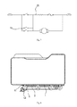
- FIG. 11 is a schematic circuit diagram of an automatic water-adding vaporization pot according to an eighth embodiment of the present disclosure.
- FIG. 13 is a cross-sectional view of the automatic water-adding vaporization pot according to a ninth embodiment of the present disclosure.
- a conventional temperature controller is generally directly mounted on the pot body, in other words, the temperature controller can detect a temperature of the pot body directly.
- the temperature controller can detect the decreased temperature immediately (i.e. there is no delay for detecting the decreased temperature by the temperature controller), a duration of adding water to the water pump cannot be met.
- a conventional solution is to detect a water level with an electric contact due to an influence of hard water, however, a detection accuracy is poor.
- the first temperature acquisition board 3 plays a role of controlling a temperature-sensing.
- a water quantity is decreased, an amount of heat transferred from the heating component 2 to the first temperature acquisition board 3 is increased, and thus the first temperature acquisition board 3 can be quickly heated up.
- the water-shortage and temperature sensing element 5 detects a change of the temperature and controls the water pump to fill water into the pot body 1 . Once the pot body 1 is filled with water, the temperature of the pot body 1 is decreased quickly. Due to a heat capacity of the first temperature acquisition board 3 and a temperature compensation effect of the heating component 2 , however, the decreased internal temperature of the pot body 1 influences the temperature of the first temperature acquisition board 3 with a delay, i.e.
- the first temperature acquisition board 3 may not be quickly cooled down, such that a dropped temperature of the first temperature acquisition board 3 is detected by the water-shortage and temperature sensing element 5 , after the temperature of the pot body 1 has been decreased a while.
- a duration of the delay equals to the duration of adding water of the water pump.
- the duration of adding water of the water pump can be calculated according to a volume of the pot body 1 , and a mounting location of the water-shortage and temperature sensing element 5 on the first temperature acquisition board 3 is determined accordingly.
- the water-shortage and temperature sensing element 5 in the embodiment of the present disclosure is a temperature controller or a temperature sensitive resistor.
- the solution of the present disclosure is different from the conventional solution such that the internal temperature of the pot body 1 is directly measured by a temperature sensing element 5 .
- the first temperature acquisition board 3 is used as a reference for measuring temperature.
- Such an indirect detection method for detecting temperature has adjustability and is favorable for adjustments of both a reference temperature and a measurement temperature of the temperature sensing element 5 , so as to achieve the continuous water-adding.
- the first temperature acquisition board 3 in the embodiment of the present disclosure plays roles of both transferring and collecting heat.
- the first temperature acquisition board 3 plays a role of stable calibration for a temperature control element at an initial stage. During ordinary work, the first temperature acquisition board 3 has a stable temperature, which may better meet a requirement of the detection of the temperature sensing element 5 .
- a running time of the water pump is depended on a heat transfer rate and a heat capacity of the first temperature acquisition board 3 .
- the heat transfer rate and the heat capacity of the first temperature acquisition board 3 are depended on a mounting position, a volume and a shape of the first temperature acquisition board 3 .
- the running time of the water pump is depended on relative positions between the first temperature acquisition board 3 and an inlet of the pot body 1 .
- the running time of the water pump may be adjusted by adjusting above parameters.
- the first temperature acquisition board 3 and the heating component 2 are formed integrally.
- the heating component 2 in the embodiment of the present disclosure may be configured a heating plate, and the first temperature acquisition board 3 and the heating plate 2 may adopts a same material.
- the first temperature acquisition board 3 may also use other material, such as a metal material or a ceramic material.
- the first temperature acquisition board 3 and the heating plate 2 may be connected together by welding or bolt connection, in which the bolt connection means connecting the first temperature acquisition board 3 and the heating plate 2 by screw or bolt.
- the heating plate 2 is provided with a heating tube 21 , and the one end of the first temperature acquisition board 3 is located at the heating tube 21 , such that the first temperature acquisition board 3 may promptly reflect a temperature change of the of the heating plate 2 , thus exactly detecting the change of the temperature.
- the one end 31 of the first temperature acquisition board 3 is bent and then connected with the heating plate 2 , and an interval between the remaining part 32 of the first temperature acquisition board 3 and the pot body 1 ranges from 0.5 mm to 20 mm. In this embodiment, the interval is 5 mm. Since there is the above interval between the remaining part 32 of the first temperature acquisition board 3 and the pot body 1 , the pot body 1 may not directly contact the temperature sensing element.
- a mounting hole 33 is formed in the part 32 of the first temperature acquisition board 3 away from the pot body 1 , a support member 34 is mounted in the mounting hole 33 , and a bottom of the support member 34 is supported on the pot body 1 .
- the support member 34 may not only play a role of supporting for the first temperature acquisition board 3 but also be used as a connector for mounting the water-shortage and temperature sensing element 5 . It is not easy for a deformation occurring to the remaining part 32 of the first temperature acquisition board 3 away from the pot body 1 because of an existence of the support member 34 .
- first temperature acquisition board 3 in the second embodiment is connected to the pot body 1 , and a connecting position is in proximity to the heating body 2 .
- Other structures, function and working principle of this embodiment are the same as the above embodiment.
- a second water-shortage and temperature sensing element may be also provided on the second temperature acquisition board 6 , and the first water-shortage and temperature sensing element 5 and the second water-shortage and temperature sensing element are configured for a high temperature detection and a low temperature detection respectively.
- a control for automatic water-adding is achieved by calculating a temperature difference or a temperature variation between the two water-shortage and temperature sensing elements.
- the first temperature acquisition board 3 is provided with the water-shortage and temperature sensing element 5 and a temperature sensor 61 for controlling the steam pressure. Because a temperature of the first temperature acquisition board 3 may exactly reflect the temperature of the heating plate, the temperature sensor 61 may be promptly activated so as to make the steam pressure in the pot body stable. Other structures of this embodiment are identical with the above two embodiments.
- the water-shortage and temperature sensing element 5 is a double-throw temperature controller that has two groups of contacts simultaneously being activated, in which one group of contacts controls the running of the water pump and the other group of contacts controls the power supply circuit 22 of the heating component 2 to work.
- This power supply circuit may enable the heating component 2 to go on working while the water pump is running.
- the heating component 2 will stop working until the pot body 1 is filled with water.
- the heating component 2 starts to heat while the water pump is working, which not only improve a generating speed of the steam, but also ensure a stability of the steam.
- a high temperature water-shortage and temperature sensing element is connected into the power supply circuit 22 of the heating component 2 .
- the heating component 2 is connected at the high temperature, and once the temperature is reduced, it switches to an ordinary power supply circuit.
- a controller mode may also be used, such that once a controller receives an activation signal from the water-shortage and temperature sensing element, the controller controls the heating component 2 to work.
- the heating component 2 is brazed to the bottom of the pot body 1 .
- a plurality of connection elements 4 are disposed at the bottom of the pot body 1 , and the heating component 2 is provided with through holes 41 through which the connection elements 4 penetrate, so that the heating component 2 is fastened to the bottom of the pot body 1 via the connection elements 4 .
- connection elements 4 are presented at the bottom of the pot body 1 , for example, the connection elements 4 may be pre-welded at the bottom of the pot body 1 , and the heating component 2 is fixed at the bottom of the pot body 1 by both fastening of the connection elements 4 and brazing during assembling.
- connection elements 4 may be also arranged at the bottom of the pot body 1 uniformly in other pattern so as to make the heating component 2 bear uniform force without creep.
- the connection elements 4 may be configured studs, one end of each connection element 4 is point welded to the bottom of the pot body 1 , and the other end of each connection element 4 secures the heating component 2 via a nut 42 .
- the stud and nut are used for securing in this embodiment; each stud is point welded to the bottom of the pot body 1 and secures the heating component 2 via the nut.
- connection elements 4 may also configured rivets, one end of each rivet is point welded to the bottom of the pot body 1 , and the other end of each rivet is riveted to the heating component 2 .
- a riveting structure is used in this mode.
- connection elements are provided between reinforcing ribs at the bottom of the pot body 1 .
- a reinforcing structure is formed at the connection elements 4 .
- the reinforcing structure at the connection elements 4 reduces the creep of the aluminum sheet caused by different coefficients of thermal expansion.
- a part of the bottom of the pot body 1 between the reinforcing ribs and the connection elements 4 may keep minimum deformation under a pressure of the pot body 1 , and thus the heating tube is disposed at this part more stably, and an edge cracking of the aluminum sheet is reduced.
- a reinforcing column 7 is disposed within the pot body 1 , one end of the reinforcing column 7 is connected with an inner surface of a bottom of the pot body 1 , and the other end of the reinforcing column 7 is connected with a top of the pot body 1 .
- the pot body 1 in the embodiment of the present disclosure consists of an upper pot body 11 and a lower pot body 12 .
- a through hole 13 with a flanging is formed inward at a top of the upper pot body 11 .
- a top of the reinforcing column 7 is welded in the through hole 13 , and a bottom of the reinforcing column 7 is welded to an inner surface of a bottom of the lower pot body 12 .
- a spacer 14 is further disposed at the through hole 13 .
- the spacer 14 is favorable for the welding of the reinforcing column 7 and plays a role of protection for the upper pot body 11 .
- a groove 71 is formed at the top and bottom of the reinforcing column 7 respectively.
- the groove 71 is favorable for the welding of the reinforcing column 7 . With the groove 71 , the heat may be concentrated at a welding part during the welding, thus improving a welding efficiency and reducing a welding time.
- a protection circuit 8 for dry burning prevention comprises a PTC thermal protector 81 for sensing a dry burning temperature, and the PTC thermal protector 81 is connected with a heating control circuit of the heating component 2 .
- contacts of the PTC thermal protector are connected in series in the heating control circuit of the heating component 2 .
- the PTC thermal protector is activated.
- a PTC heating element in the PTC thermal protector is on and heated, thus keeping the contacts of the PTC thermal protector always activated instead of resetting.
- Such PTC thermal protector may be purchased from a market.
- the PTC thermal protector is provided as a temperature controller for dry burning prevention, such that a heater may be not on and off repeatedly, thus extending service lives of related devices.
- the PTC thermal protector may also be mounted on the first temperature acquisition board 3 , such that a dry burning signal can be exactly detected and the protection for the dry burning is timely.
- the first temperature acquisition board 3 is formed by a middle part of the heating component 2 which is protruded outward, and the first temperature acquisition board 3 is connected with the heating component 2 via a connecting leg 39 .
- the first temperature acquisition board 3 is formed by protruding the middle part of the heating component 2 outside, such that the first temperature acquisition board 3 is away from the pot body 1 and plays the same role as that in each embodiment described above.
- the first temperature acquisition board 3 is connected with the heating component 2 via the connecting leg 39 located at one side.
- the connecting leg 39 is configured for transferring heat. Therefore, a time period for transferring heat may be controlled by adjusting a size of the connecting leg 39 .
- both sides of the first temperature acquisition board 3 are connected with the heating component 2 via the connecting legs 39 , and the remaining parts of the first temperature acquisition board 3 are away from the heating component 2 .
- outward protruding structure may be also replaced by an inward recessing of the pot body 1 .
- a design that the connection elements 4 are arranged in inner-and-outer-circles according to the sixth embodiment is used in this embodiment.
- Other structures may use a related structure of the embodiments described above or a combination thereof.
Applications Claiming Priority (4)
| Application Number | Priority Date | Filing Date | Title |
|---|---|---|---|
| CN201210318454.4 | 2012-08-31 | ||
| CN201210318454 | 2012-08-31 | ||
| CN201210318454.4A CN103672836B (zh) | 2012-08-31 | 2012-08-31 | 一种自动加水汽化锅 |
| PCT/CN2013/001024 WO2014032400A1 (zh) | 2012-08-31 | 2013-08-30 | 一种自动加水汽化锅 |
Publications (2)
| Publication Number | Publication Date |
|---|---|
| US20150233573A1 US20150233573A1 (en) | 2015-08-20 |
| US9677757B2 true US9677757B2 (en) | 2017-06-13 |
Family
ID=50182423
Family Applications (1)
| Application Number | Title | Priority Date | Filing Date |
|---|---|---|---|
| US14/422,659 Expired - Fee Related US9677757B2 (en) | 2012-08-31 | 2013-08-30 | Automatic water-adding vaporization pot |
Country Status (5)
| Country | Link |
|---|---|
| US (1) | US9677757B2 (zh) |
| EP (1) | EP2905534B1 (zh) |
| CN (1) | CN103672836B (zh) |
| RU (1) | RU2600481C1 (zh) |
| WO (1) | WO2014032400A1 (zh) |
Cited By (1)
| Publication number | Priority date | Publication date | Assignee | Title |
|---|---|---|---|---|
| US20170181564A1 (en) * | 2015-12-25 | 2017-06-29 | Zhigang He | Multifunctional Cooking Pot |
Families Citing this family (5)
| Publication number | Priority date | Publication date | Assignee | Title |
|---|---|---|---|---|
| CN103672836B (zh) * | 2012-08-31 | 2016-08-24 | 宁波新乐生活电器有限公司 | 一种自动加水汽化锅 |
| EP3540329B1 (en) * | 2016-06-20 | 2021-04-28 | Bleckmann GmbH & Co. KG | Heating system component providing a compact temperature sensor design |
| US10598549B2 (en) * | 2016-08-04 | 2020-03-24 | The Vollrath Company, L.L.C. | Wireless temperature probe |
| US11134321B2 (en) | 2016-08-04 | 2021-09-28 | The Vollrath Company, L.L.C. | Wireless temperature probe |
| EP4009741A1 (en) * | 2020-12-03 | 2022-06-08 | Bleckmann GmbH & Co. KG | Heating system component for sensing a first and second temperature |
Citations (44)
| Publication number | Priority date | Publication date | Assignee | Title |
|---|---|---|---|---|
| US2437963A (en) * | 1943-03-24 | 1948-03-16 | Gen Electric | Method and apparatus for producing aerosols |
| US2561932A (en) * | 1949-01-06 | 1951-07-24 | Hudson Mfg Co H D | Float type immersion heater for tanks and the like |
| US2686863A (en) * | 1951-08-07 | 1954-08-17 | Edward F Chandler | Fluid heating and circulating device |
| US2785271A (en) * | 1953-10-08 | 1957-03-12 | Hal H Baly | Steam generator |
| US4000396A (en) * | 1972-09-26 | 1976-12-28 | North American Systems, Inc. | Instant brewing pour-in instant electric coffee maker |
| US4460819A (en) * | 1983-01-11 | 1984-07-17 | Intropa Trading S.A. | Instantaneous flow-through electric water heater for coffee makers |
| US4634838A (en) * | 1983-09-29 | 1987-01-06 | Intropa S.A. | Electrically heated coffee percolator |
| US4668854A (en) * | 1985-08-13 | 1987-05-26 | Napco Scientific Company | Humidification system |
| US4835366A (en) * | 1987-10-07 | 1989-05-30 | Allied Precision Industries, Inc. | Portable temperature controlled floating electric immersion heater for a livestock water tank |
| US4881493A (en) * | 1986-03-11 | 1989-11-21 | Riba Guenther | Steam generator |
| US5150448A (en) * | 1989-12-15 | 1992-09-22 | Melitta Haushalts-Produkte GmbH & Co., KG | Beverage flow heater utilizing heated tube with discrete heating zone |
| US5367607A (en) * | 1991-09-13 | 1994-11-22 | Braun Aktiengesellschaft | Brewed beverage maker with unpressurized boiler vessel steam generator tube and common heating element |
| US5459812A (en) * | 1990-09-17 | 1995-10-17 | Strix Limited | Immersion heaters including sheet metal heat conduction link |
| US5651905A (en) * | 1995-06-07 | 1997-07-29 | The West Bend Company | Heating device for a small appliance |
| FR2755706A1 (fr) | 1996-11-13 | 1998-05-15 | Seb Sa | Generateur de vapeur |
| US5881207A (en) * | 1995-10-31 | 1999-03-09 | Seb Sa | Steam generator with automatic supply and a process for measuring the level of liquid in such a generator |
| US5933575A (en) * | 1998-03-19 | 1999-08-03 | Sanders; Clifton Omer | Water heating appliance for hottub or spa |
| US6148144A (en) * | 1999-01-27 | 2000-11-14 | Euroflex Srl | Portable linear shaped steam cleaner |
| US6243535B1 (en) * | 1997-02-14 | 2001-06-05 | Ecovap S.A. | Steam generator |
| CN2531178Y (zh) | 2001-10-26 | 2003-01-15 | 马有江 | 一种温控截止阀 |
| US20030142965A1 (en) * | 2002-01-29 | 2003-07-31 | Kable Enterprises Co., Ltd. | Steam-cleaning appliance |
| US6915070B1 (en) * | 2004-09-03 | 2005-07-05 | Ming-Tsung Lee | Quick heater for drinking water |
| US20060291828A1 (en) * | 2003-09-10 | 2006-12-28 | Tetsuya Kadoma | Vapor production device and cooker with the same |
| CN101278794A (zh) | 2008-05-20 | 2008-10-08 | 江苏科技大学 | 蒸汽型电热毯 |
| US20080247740A1 (en) * | 2005-09-19 | 2008-10-09 | Koninklijke Philips Electronics N.V. | Device for Making a Beverage, Provided with a Water Boiler |
| CN201184587Y (zh) | 2007-11-05 | 2009-01-21 | 邵博言 | 具有自动加水控制系统的蒸汽锅炉 |
| US20100011629A1 (en) * | 2006-12-18 | 2010-01-21 | Koninklijke Philips Electronics N.V. | Device for supplying superheated water |
| US20100021146A1 (en) * | 2006-07-26 | 2010-01-28 | Takao Murai | Vapor generation device and cooking device |
| US20100116812A1 (en) * | 2008-11-07 | 2010-05-13 | General Electric Company | Dry fire protection system |
| CN201473803U (zh) | 2009-08-21 | 2010-05-19 | 浙江华光电器集团有限公司 | 蒸汽挂烫机改进结构 |
| CN101799153A (zh) | 2009-07-09 | 2010-08-11 | 姜豪奎 | 高效蒸汽发生装置及其水位控制方法 |
| US7813628B2 (en) * | 2006-12-13 | 2010-10-12 | Gyung-Hee Haan | Instantaneous steam boiler |
| CN101925206A (zh) | 2010-07-15 | 2010-12-22 | 李嘉琪 | 一种电加热装置及使用该电加热装置的电加热器 |
| US20110058798A1 (en) * | 2007-12-24 | 2011-03-10 | Strix Limited | Liquid heating apparatus |
| US7920778B2 (en) * | 2004-12-22 | 2011-04-05 | Koninklijke Philips Electronics N.V. | Boiler for use in a steam generating device |
| US8146275B2 (en) * | 2008-11-20 | 2012-04-03 | Tsann Kuen (Zhangzhou) Enterprise Co., Ltd. | Steam iron |
| CN202298269U (zh) | 2011-10-09 | 2012-07-04 | 宁波新乐生活电器有限公司 | 一种改良的大容量汽化锅 |
| US20130055902A1 (en) * | 2010-05-21 | 2013-03-07 | Koninklijke Philips Electronics N.V. | Device for heating water and producing steam |
| CN202835311U (zh) | 2012-08-31 | 2013-03-27 | 宁波新乐生活电器有限公司 | 一种液体电加热容器 |
| CN202835312U (zh) | 2012-08-31 | 2013-03-27 | 宁波新乐生活电器有限公司 | 一种自动加水汽化锅 |
| US8616157B2 (en) * | 2005-12-19 | 2013-12-31 | Koninklijke Philips N.V. | Apparatus and method for generating steam |
| US20150233572A1 (en) * | 2013-03-14 | 2015-08-20 | Panasonic Intellectual Property Management Co., Ltd. | Steam generator |
| US20150233573A1 (en) * | 2012-08-31 | 2015-08-20 | Ningbo Xinle Small Domestic Appliance Co., Ltd | Automatic water-adding vaporization pot |
| US20160161108A1 (en) * | 2013-07-25 | 2016-06-09 | Koninklijke Philips N.V. | Apparatus for generating steam |
Family Cites Families (13)
| Publication number | Priority date | Publication date | Assignee | Title |
|---|---|---|---|---|
| SU366310A1 (ru) * | 1971-12-20 | 1973-01-16 | Всесоюзная | |
| US4455477A (en) * | 1980-04-16 | 1984-06-19 | Zip Heaters (Aust) Pty. Limited | Electric boiling water heater |
| IT1185051B (it) * | 1985-03-08 | 1987-11-04 | E G O Italiana Spa | Apparecchio per generare del vapore,in particolare per dispositivi di cottura |
| SU1373973A1 (ru) * | 1986-08-05 | 1988-02-15 | Киевский институт автоматики им.ХХУ съезда КПСС | Система регулировани температурного режима и перегрева пара пр моточного котлоагрегата |
| FI117665B (fi) * | 2005-08-10 | 2007-01-15 | F E M Ltd | Höyrynkehitin |
| EP1975308A1 (en) * | 2007-03-30 | 2008-10-01 | Koninklijke Philips Electronics N.V. | Method for determining the liquid level in a boiler |
| CN201094538Y (zh) * | 2007-08-28 | 2008-08-06 | 甘跃斌 | 一种快速电热壶的底部结构 |
| CN201139431Y (zh) * | 2007-12-08 | 2008-10-29 | 方士达 | 一种电加热容器 |
| CN201429123Y (zh) * | 2009-04-29 | 2010-03-24 | 夏云彪 | 装置温度采集板的电磁炉 |
| CN201715680U (zh) * | 2010-07-02 | 2011-01-19 | 佛山市顺德区兆坚电器制造有限公司 | 电热水器 |
| CN202195572U (zh) * | 2011-08-12 | 2012-04-18 | 杭州热威机电有限公司 | 和泵相结合的加热器 |
| CN203338886U (zh) * | 2011-12-20 | 2013-12-11 | 江苏神马电力股份有限公司 | 一种800kV气体绝缘复合套管 |
| CN102637594B (zh) * | 2012-03-19 | 2017-08-22 | 晶能光电(江西)有限公司 | 对外延片进行退火合金的装置及方法 |
-
2012
- 2012-08-31 CN CN201210318454.4A patent/CN103672836B/zh not_active Expired - Fee Related
-
2013
- 2013-08-30 RU RU2015108129/06A patent/RU2600481C1/ru not_active IP Right Cessation
- 2013-08-30 US US14/422,659 patent/US9677757B2/en not_active Expired - Fee Related
- 2013-08-30 WO PCT/CN2013/001024 patent/WO2014032400A1/zh active Application Filing
- 2013-08-30 EP EP13833430.5A patent/EP2905534B1/en not_active Not-in-force
Patent Citations (46)
| Publication number | Priority date | Publication date | Assignee | Title |
|---|---|---|---|---|
| US2437963A (en) * | 1943-03-24 | 1948-03-16 | Gen Electric | Method and apparatus for producing aerosols |
| US2561932A (en) * | 1949-01-06 | 1951-07-24 | Hudson Mfg Co H D | Float type immersion heater for tanks and the like |
| US2686863A (en) * | 1951-08-07 | 1954-08-17 | Edward F Chandler | Fluid heating and circulating device |
| US2785271A (en) * | 1953-10-08 | 1957-03-12 | Hal H Baly | Steam generator |
| US4000396A (en) * | 1972-09-26 | 1976-12-28 | North American Systems, Inc. | Instant brewing pour-in instant electric coffee maker |
| US4460819A (en) * | 1983-01-11 | 1984-07-17 | Intropa Trading S.A. | Instantaneous flow-through electric water heater for coffee makers |
| US4634838A (en) * | 1983-09-29 | 1987-01-06 | Intropa S.A. | Electrically heated coffee percolator |
| US4668854A (en) * | 1985-08-13 | 1987-05-26 | Napco Scientific Company | Humidification system |
| US4881493A (en) * | 1986-03-11 | 1989-11-21 | Riba Guenther | Steam generator |
| US4835366A (en) * | 1987-10-07 | 1989-05-30 | Allied Precision Industries, Inc. | Portable temperature controlled floating electric immersion heater for a livestock water tank |
| US5150448A (en) * | 1989-12-15 | 1992-09-22 | Melitta Haushalts-Produkte GmbH & Co., KG | Beverage flow heater utilizing heated tube with discrete heating zone |
| US5459812A (en) * | 1990-09-17 | 1995-10-17 | Strix Limited | Immersion heaters including sheet metal heat conduction link |
| US5367607A (en) * | 1991-09-13 | 1994-11-22 | Braun Aktiengesellschaft | Brewed beverage maker with unpressurized boiler vessel steam generator tube and common heating element |
| US5651905A (en) * | 1995-06-07 | 1997-07-29 | The West Bend Company | Heating device for a small appliance |
| US5881207A (en) * | 1995-10-31 | 1999-03-09 | Seb Sa | Steam generator with automatic supply and a process for measuring the level of liquid in such a generator |
| FR2755706A1 (fr) | 1996-11-13 | 1998-05-15 | Seb Sa | Generateur de vapeur |
| EP0843039A1 (fr) | 1996-11-13 | 1998-05-20 | Seb S.A. | Générateur de vapeur |
| US6243535B1 (en) * | 1997-02-14 | 2001-06-05 | Ecovap S.A. | Steam generator |
| US5933575A (en) * | 1998-03-19 | 1999-08-03 | Sanders; Clifton Omer | Water heating appliance for hottub or spa |
| US6148144A (en) * | 1999-01-27 | 2000-11-14 | Euroflex Srl | Portable linear shaped steam cleaner |
| CN2531178Y (zh) | 2001-10-26 | 2003-01-15 | 马有江 | 一种温控截止阀 |
| US20030142965A1 (en) * | 2002-01-29 | 2003-07-31 | Kable Enterprises Co., Ltd. | Steam-cleaning appliance |
| US7509034B2 (en) * | 2003-09-10 | 2009-03-24 | Sharp Kabushiki Kaisha | Vapor production device and cooker with the same |
| US20060291828A1 (en) * | 2003-09-10 | 2006-12-28 | Tetsuya Kadoma | Vapor production device and cooker with the same |
| US6915070B1 (en) * | 2004-09-03 | 2005-07-05 | Ming-Tsung Lee | Quick heater for drinking water |
| US7920778B2 (en) * | 2004-12-22 | 2011-04-05 | Koninklijke Philips Electronics N.V. | Boiler for use in a steam generating device |
| US20080247740A1 (en) * | 2005-09-19 | 2008-10-09 | Koninklijke Philips Electronics N.V. | Device for Making a Beverage, Provided with a Water Boiler |
| US8616157B2 (en) * | 2005-12-19 | 2013-12-31 | Koninklijke Philips N.V. | Apparatus and method for generating steam |
| US20100021146A1 (en) * | 2006-07-26 | 2010-01-28 | Takao Murai | Vapor generation device and cooking device |
| US7813628B2 (en) * | 2006-12-13 | 2010-10-12 | Gyung-Hee Haan | Instantaneous steam boiler |
| US20100011629A1 (en) * | 2006-12-18 | 2010-01-21 | Koninklijke Philips Electronics N.V. | Device for supplying superheated water |
| CN201184587Y (zh) | 2007-11-05 | 2009-01-21 | 邵博言 | 具有自动加水控制系统的蒸汽锅炉 |
| US20110058798A1 (en) * | 2007-12-24 | 2011-03-10 | Strix Limited | Liquid heating apparatus |
| CN101278794A (zh) | 2008-05-20 | 2008-10-08 | 江苏科技大学 | 蒸汽型电热毯 |
| US20100116812A1 (en) * | 2008-11-07 | 2010-05-13 | General Electric Company | Dry fire protection system |
| US8146275B2 (en) * | 2008-11-20 | 2012-04-03 | Tsann Kuen (Zhangzhou) Enterprise Co., Ltd. | Steam iron |
| CN101799153A (zh) | 2009-07-09 | 2010-08-11 | 姜豪奎 | 高效蒸汽发生装置及其水位控制方法 |
| CN201473803U (zh) | 2009-08-21 | 2010-05-19 | 浙江华光电器集团有限公司 | 蒸汽挂烫机改进结构 |
| US20130055902A1 (en) * | 2010-05-21 | 2013-03-07 | Koninklijke Philips Electronics N.V. | Device for heating water and producing steam |
| CN101925206A (zh) | 2010-07-15 | 2010-12-22 | 李嘉琪 | 一种电加热装置及使用该电加热装置的电加热器 |
| CN202298269U (zh) | 2011-10-09 | 2012-07-04 | 宁波新乐生活电器有限公司 | 一种改良的大容量汽化锅 |
| CN202835311U (zh) | 2012-08-31 | 2013-03-27 | 宁波新乐生活电器有限公司 | 一种液体电加热容器 |
| CN202835312U (zh) | 2012-08-31 | 2013-03-27 | 宁波新乐生活电器有限公司 | 一种自动加水汽化锅 |
| US20150233573A1 (en) * | 2012-08-31 | 2015-08-20 | Ningbo Xinle Small Domestic Appliance Co., Ltd | Automatic water-adding vaporization pot |
| US20150233572A1 (en) * | 2013-03-14 | 2015-08-20 | Panasonic Intellectual Property Management Co., Ltd. | Steam generator |
| US20160161108A1 (en) * | 2013-07-25 | 2016-06-09 | Koninklijke Philips N.V. | Apparatus for generating steam |
Non-Patent Citations (1)
| Title |
|---|
| International Search Report of International Application No. PCT/CN2013/001024 with English translation, mailed Dec. 12, 2013, 10 pages. |
Cited By (1)
| Publication number | Priority date | Publication date | Assignee | Title |
|---|---|---|---|---|
| US20170181564A1 (en) * | 2015-12-25 | 2017-06-29 | Zhigang He | Multifunctional Cooking Pot |
Also Published As
| Publication number | Publication date |
|---|---|
| RU2600481C1 (ru) | 2016-10-20 |
| US20150233573A1 (en) | 2015-08-20 |
| EP2905534B1 (en) | 2018-04-11 |
| CN103672836A (zh) | 2014-03-26 |
| EP2905534A1 (en) | 2015-08-12 |
| WO2014032400A1 (zh) | 2014-03-06 |
| CN103672836B (zh) | 2016-08-24 |
| EP2905534A4 (en) | 2016-07-13 |
Similar Documents
| Publication | Publication Date | Title |
|---|---|---|
| US9677757B2 (en) | Automatic water-adding vaporization pot | |
| US20110248020A1 (en) | Electromagnetic oven for barbecue | |
| WO2015149437A1 (zh) | 设置多感温探头的蒸煮锅具及一种蒸煮食物的方法 | |
| CN202835311U (zh) | 一种液体电加热容器 | |
| CN205053827U (zh) | 电锅 | |
| CN204931274U (zh) | 微型电饭煲的加热体弹性支撑结构 | |
| CN103672837B (zh) | 一种液体电加热容器 | |
| JP2007263507A (ja) | コンロ | |
| CN100595488C (zh) | 精确测温的电加热灶具及电加热灶具精确测温的方法 | |
| JP2510895Y2 (ja) | サ―モスタットの受熱体 | |
| CN110274701B (zh) | 一种烹饪电器蒸发盘的温度传感器固定装置 | |
| CN211242765U (zh) | 一种具有过热保护功能的炒菜机 | |
| CN211269931U (zh) | 一种双发热管炒菜机 | |
| CN210601762U (zh) | 一种精准控温的电磁炉 | |
| CN203454083U (zh) | 一种液体电加热容器 | |
| CN219982697U (zh) | 温控器安装结构及包括该温控器安装结构的电火锅 | |
| CN211242947U (zh) | 一种发热盘 | |
| CN220423759U (zh) | 一种控温精准的多功能锅 | |
| CN217039769U (zh) | 一种感温件安装结构及烹饪电器 | |
| CN216869790U (zh) | 一种燃气器具温度传感器 | |
| CN214180081U (zh) | 一种避免干烧的关东煮机 | |
| CN214180099U (zh) | 一种液体加热器的防干烧结构及液体加热器 | |
| CN219733734U (zh) | 一种结合温控组件的加热泵盖及加热泵 | |
| AU2012265567B2 (en) | Temperature sensing for an electric heating device | |
| CN217403632U (zh) | 烹饪器具的温度传感器 |
Legal Events
| Date | Code | Title | Description |
|---|---|---|---|
| AS | Assignment |
Owner name: NINGBO XINLE SMALL DOMESTIC APPLIANCE CO., LTD., C Free format text: ASSIGNMENT OF ASSIGNORS INTEREST;ASSIGNOR:KE, YU;REEL/FRAME:035812/0729 Effective date: 20150209 |
|
| STCF | Information on status: patent grant |
Free format text: PATENTED CASE |
|
| FEPP | Fee payment procedure |
Free format text: MAINTENANCE FEE REMINDER MAILED (ORIGINAL EVENT CODE: REM.); ENTITY STATUS OF PATENT OWNER: SMALL ENTITY |
|
| LAPS | Lapse for failure to pay maintenance fees |
Free format text: PATENT EXPIRED FOR FAILURE TO PAY MAINTENANCE FEES (ORIGINAL EVENT CODE: EXP.); ENTITY STATUS OF PATENT OWNER: SMALL ENTITY |
|
| STCH | Information on status: patent discontinuation |
Free format text: PATENT EXPIRED DUE TO NONPAYMENT OF MAINTENANCE FEES UNDER 37 CFR 1.362 |
|
| FP | Lapsed due to failure to pay maintenance fee |
Effective date: 20210613 |