US9649907B2 - Vehicle air-conditioner - Google Patents
Vehicle air-conditioner Download PDFInfo
- Publication number
- US9649907B2 US9649907B2 US13/456,603 US201213456603A US9649907B2 US 9649907 B2 US9649907 B2 US 9649907B2 US 201213456603 A US201213456603 A US 201213456603A US 9649907 B2 US9649907 B2 US 9649907B2
- Authority
- US
- United States
- Prior art keywords
- air
- passage
- evaporator
- disposed
- conditioned
- Prior art date
- Legal status (The legal status is an assumption and is not a legal conclusion. Google has not performed a legal analysis and makes no representation as to the accuracy of the status listed.)
- Active, expires
Links
Images


Classifications
-
- B—PERFORMING OPERATIONS; TRANSPORTING
- B60—VEHICLES IN GENERAL
- B60H—ARRANGEMENTS OF HEATING, COOLING, VENTILATING OR OTHER AIR-TREATING DEVICES SPECIALLY ADAPTED FOR PASSENGER OR GOODS SPACES OF VEHICLES
- B60H1/00—Heating, cooling or ventilating [HVAC] devices
- B60H1/00007—Combined heating, ventilating, or cooling devices
- B60H1/00021—Air flow details of HVAC devices
- B60H1/00064—Air flow details of HVAC devices for sending air streams of different temperatures into the passenger compartment
-
- B—PERFORMING OPERATIONS; TRANSPORTING
- B60—VEHICLES IN GENERAL
- B60H—ARRANGEMENTS OF HEATING, COOLING, VENTILATING OR OTHER AIR-TREATING DEVICES SPECIALLY ADAPTED FOR PASSENGER OR GOODS SPACES OF VEHICLES
- B60H1/00—Heating, cooling or ventilating [HVAC] devices
- B60H1/00007—Combined heating, ventilating, or cooling devices
- B60H1/00021—Air flow details of HVAC devices
- B60H2001/00078—Assembling, manufacturing or layout details
- B60H2001/00085—Assembling, manufacturing or layout details of air intake
-
- B—PERFORMING OPERATIONS; TRANSPORTING
- B60—VEHICLES IN GENERAL
- B60H—ARRANGEMENTS OF HEATING, COOLING, VENTILATING OR OTHER AIR-TREATING DEVICES SPECIALLY ADAPTED FOR PASSENGER OR GOODS SPACES OF VEHICLES
- B60H1/00—Heating, cooling or ventilating [HVAC] devices
- B60H1/00007—Combined heating, ventilating, or cooling devices
- B60H1/00021—Air flow details of HVAC devices
- B60H2001/00078—Assembling, manufacturing or layout details
- B60H2001/00099—Assembling, manufacturing or layout details comprising additional ventilating means
-
- B—PERFORMING OPERATIONS; TRANSPORTING
- B60—VEHICLES IN GENERAL
- B60H—ARRANGEMENTS OF HEATING, COOLING, VENTILATING OR OTHER AIR-TREATING DEVICES SPECIALLY ADAPTED FOR PASSENGER OR GOODS SPACES OF VEHICLES
- B60H1/00—Heating, cooling or ventilating [HVAC] devices
- B60H1/00007—Combined heating, ventilating, or cooling devices
- B60H1/00021—Air flow details of HVAC devices
- B60H2001/00114—Heating or cooling details
- B60H2001/00135—Deviding walls for separate air flows
Definitions
- the present invention relates to a vehicle air-conditioner capable of introducing air from outside a vehicle passenger compartment (outside air) and air from inside the vehicle passenger compartment (inside air) to generate conditioned air and blowing the conditioned air into the vehicle passenger compartment.
- Some known vehicle air-conditioners include an outside air passage and an inside air passage that are provided separately for guiding outside air and inside air, respectively.
- the known vehicle air-conditioners In a heat mode or a heat/defrost mode, the known vehicle air-conditioners circulate the inside air, having been already heated within a passenger compartment of the vehicle, through the inside air passage and blow the circulated inside air from heat outlets as a conditioned air to thereby heat the passenger compartment at a proper temperature.
- the outside air is introduced into the outside air passage to generate a conditioned air having a low level of humidity and the conditioned air is blown from defrost nozzles toward windowpanes to keep good antifogging property of the windowpanes.
- the known vehicle air-conditioners are able to improve passenger-compartment heating power or capacity and secure good windowpane anti-fogging property in the heat mode or the heat/defrost mode.
- One example of such known vehicle air-conditioners is disclosed in Japanese Patent No. 3684712 corresponding to Japanese Patent Application Laid-open Publication (JP-A) No. 10-109520.
- the disclosed vehicle air-conditioner is not able to blow the outside air and the inside air concurrently, via the outside air passage and the inside air passage, respectively, into the passenger compartment while it is operating in a normal stable stat.
- the term “normal stable state” is used herein to refer to a state in which the volume of conditioned air blown into the passenger compartment and the temperature of the passenger compartment are set in an intermediate range.
- the disclosed vehicle air-conditioner is operating in the normal stable state in the bi-level mode or the hat mode, one of the outside air and the inside air is solely used to generate conditioned air to be blown into the passenger compartment.
- This arrangement makes it difficult to achieve a good balance between passenger-compartment temperature comfort and windowpanes anti-fogging property.
- the conditioned air generated solely from the outside air or inside air is heated or cooled before being blown into the passenger compartment. Such additional heating or cooling will increase energy consumption of the vehicle air-conditioner.
- an object of the present invention to provide a vehicle air-conditioner, which is capable of securing a good balance of passenger-compartment temperature comfort and windowpanes anti-fogging property, and also achieving a reduction in energy consumption.
- an air-conditioner for a vehicle comprising: a first air inlet for selectively introducing outside air from outside a passenger compartment of the vehicle and inside air from inside the passenger compartment; a second air inlet for selectively introducing the inside air and the outside air; a first passage communicating with the first air inlet and capable of communicating to a defrost outlet, a side defrost outlet and a side vent outlet; a second passage communicating with the second air inlet and capable of communicating to a center vent outlet and a heat outlet; and an evaporator and a heater core disposed in the first and second passages in the named order as viewed from the first and second air inlets, wherein the air-conditioner is capable of operating in plural different modes, and in at least one of the plural different modes, the outside air introduced from the first air inlet into the first passage is conditioned by the evaporator and the heater core and subsequently blown, as a first conditioned air, from the defrost outlet, side de
- the inside air which is already kept at a proper temperature within the passenger compartment is circulated through the second passage and blown, as a conditioned air, from the respective outlets (center vent outlet and heat outlet) into the passenger compartment.
- the degree of air-conditioning i.e., cooling or heating condition
- outside air introduced from outside the passenger compartment and having a low level of humidity or a conditioned outside air is blown, as a conditioned air, from the defrost outlet, side defrost outlet and side vent outlet toward the windowpanes.
- the first and second passages it is possible to circulate the inside air during operation of the vehicle air-conditioner so that the passenger compartment is always kept in a comfortable condition. Concurrently at the same time, a fog-free state of the windowpanes can be maintained by introducing the outside air. Thus, a good balance between temperature comfort of the passenger compartment and anti-fogging properties of the windowpanes can be achieved during operation of the vehicle air-conditioner. This will eliminate undue heating and cooling of the passenger compartment by the conditioned air blown into the passenger compartment and, hence, energy consumption of the vehicle air-conditioner can be reduced.
- the air-conditioner further includes a first fan disposed in the first passage and located between the first air inlet and the evaporator, and a second fan disposed in the second passage and located between the second air inlet and the evaporator, wherein the first fan and the second fan are individually supported on respective driving shafts.
- the evaporator is mounted to tilt in a backward direction of the vehicle, and the tilted evaporator includes a lower half disposed in the first passage and an upper half disposed in the second passage.
- This arrangement is employed for a reason described below.
- the first passage is in communication with the defrost outlet, side defrost outlet and side vent outlet, while the second passage is in communication with the center vent outlet and heat outlet.
- the humidity of the outside air is normally higher than that of the inside air
- water vapor contained in the outside air will become condensed on a tube and fins of the evaporator upper half.
- the condensed water then flows downward from the evaporator upper half to the lower half of the evaporator along the pipe and fins of the evaporator.
- the condensed water may freeze on the tube and fins of the evaporator as it flows downward from the evaporator upper half toward the evaporator lower half.
- the evaporator upper half is disposed in the first passage, so that condensed water, which has been removed from the outside air, can smoothly fall by gravity down from the evaporator without freezing on the tube and fins of the evaporator.
- the evaporator is thus free from adhesion of frozen water and, hence, the outside air and inside air can pass through the evaporator smoothly with reduced resistance. This will achieve a reduction in energy consumption of the vehicle air-conditioner.
- FIG. 1 is an exploded perspective view of a vehicle air-conditioner embodying the present invention as it is removed from an instrument panel of the vehicle;
- FIG. 2 is a schematic cross-sectional view of the vehicle air-conditioner.
- FIG. 3 is a diagrammatical view showing the relation between a fun means and an evaporator of the vehicle air-conditioner
- FIG. 4 is an enlarged view of a portion of FIG. 2 .
- FIG. 5 is a schematic plan view showing an arrangement of a duct unit of the vehicle air-conditioner
- FIG. 6A is a view similar to FIG. 3 , but showing a condition in which the vehicle air-conditioner is operating to achieve a maximum cooling state in a vent mode;
- FIG. 6B is a view similar to FIG. 2 , but showing a condition in which the vehicle air-conditioner is operating to achieve the maximum cooling state in the vent mode;
- FIG. 7 is a view similar to FIG. 5 , but showing a manner in which conditioned air is blown from the duct unit when the vehicle air-conditioner is operating in the maximum cooling state in the vent mode;
- FIG. 8A is a view similar to FIG. 3 , but showing a condition in which the vehicle air-conditioner is operating to achieve a normal stable state in the vent mode;
- FIG. 8B is a view similar to FIG. 2 , but showing a condition in which the vehicle air-conditioner is operating to achieve the normal stable state in the vent mode;
- FIG. 9 is a view similar to FIG. 5 , but showing a manner in which controlled air is blown from the duct unit when the vehicle air-conditioner is operating in the normal stable state in the vent mode;
- FIG. 10A is a view similar to FIG. 3 , but showing a condition in which the vehicle air-conditioner is operating to achieve a normal stable state in a bi-level mode;
- FIG. 10B is a view similar to FIG. 2 , but showing a condition in which the vehicle air-conditioner is operating to achieve the normal stable state in the bi-level mode;
- FIG. 11 is a view similar to FIG. 5 , but showing a manner in which controlled air is blown from the duct unit when the vehicle air-conditioner is operating in the normal stable state in the bi-level mode;
- FIG. 12A is a view similar to FIG. 3 , but showing a condition in which the vehicle air-conditioner is operating to achieve an anti-fogging state in the bi-level mode;
- FIG. 12B is a view similar to FIG. 2 , but showing a condition in which the vehicle air-conditioner is operating to achieve the anti-fogging state in the bi-level mode;
- FIG. 13 is a view similar to FIG. 5 , but showing a manner in which controlled air is blown from the duct unit when the vehicle air-conditioner is operating in the anti-fogging state in the bi-level mode;
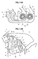
- FIG. 14A is a view similar to FIG. 3 , but showing a condition in which the vehicle air-conditioner is operating to achieve a normal stable state in a heat mode;
- FIG. 14B is a view similar to FIG. 2 , but showing a condition in which the vehicle air-conditioner is operating to achieve the normal stable state in the heat mode;
- FIG. 15 is a view similar to FIG. 5 , but showing a manner in which controlled air is blown from the duct unit when the vehicle air-conditioner is operating in the normal stable state in the heat mode;
- FIG. 16A is a view similar to FIG. 3 , but showing a condition in which the vehicle air-conditioner is operating to achieve a maximum-heating and anti-fogging state in the heat mode;
- FIG. 16B is a view similar to FIG. 2 , but showing a condition in which the vehicle air-conditioner is operating to achieve the maximum-heating and anti-fogging state in the heat mode;
- FIG. 17 is a view similar to FIG. 5 , but showing a manner in which controlled air is blown from the duct unit when the vehicle air-conditioner is operating in the maximum-heating and anti-fogging state in the heat mode;
- FIG. 18A is a view similar to FIG. 3 , but showing a condition in which the vehicle air-conditioner is operating to achieve a maximum anti-fogging state in a defrost mode;
- FIG. 18B is a view similar to FIG. 2 , but showing a condition in which the vehicle air-conditioner is operating to achieve the maximum anti-fogging state in the vent mode;
- FIG. 19 is a view similar to FIG. 5 , but showing a manner in which controlled air is blown from the duct unit when the vehicle air-conditioner is operating in the maximum anti-fogging state in the defrost mode.
- a vehicle 10 includes a passenger compartment 11 , an instrument panel 13 that partitions a front part of the passenger compartment, and a vehicle air-conditioner 15 disposed forwardly of the instrument panel 13 as viewed in a longitudinal or front-rear direction of the vehicle.
- the vehicle air-conditioner 15 includes an air-conditioning unit 16 installed in the vehicle 10 for performing air-conditioning of the interior of the passenger compartment 11 , and a duct unit 18 provided on the air-conditioning unit 16 .
- the air-conditioning unit 16 generally comprises a housing 21 disposed on a front part of the passenger compartment 11 , a fan means or device 22 disposed in the housing 21 , an evaporator 26 and a heater core 31 that are disposed downstream of the fan device 22 , and a damper means or device 35 disposed in the housing 21 for regulating the flow of air inside the housing 21 .
- the housing 21 has a first air inlet 51 for introducing outside air, a first passage 52 communicating with the first air inlet 51 , a defrost inlet (DEF inlet) 53 and a side vent inlet 54 that are in communication with the first passage 52 , a second air inlet 56 for introducing inside air, a second passage 57 communicating with the second air inlet 56 , and a center vent inlet 58 and a front and rear heat inlet 60 that are in communication with the second passage 57 .
- the first passage 52 and the second passage 57 are defined by a first partition wall 64 , a second partition wall 65 and a third partition wall 66 within the housing 21 .
- the DEF inlet 53 and the side vent inlet 54 are disposed above and forwardly of the heater core 31 .
- the center vent inlet 58 and the front and rear heat inlet 60 are disposed rearwardly of the evaporator 26 and the heater core 31 as viewed in the longitudinal direction of the vehicle body.
- the first partition wall 64 , the second partition wall 65 and the third partition wall 66 will be described later in detail.
- the fan device 22 ( FIG. 3 ) includes a first fan 23 disposed in the first passage 52 and located downstream of the first air inlet 51 , and a second fan 24 disposed in the second passage 57 and located downstream of the second air inlet 56 .
- the first fan 23 is disposed between the first air inlet 51 and the evaporator 26 (especially, a lower half 27 of the evaporator 26 ) and supported on a drive shaft 23 a of a first fan motor (not shown).
- the lower half 27 of the evaporator 26 will be hereinafter referred to for brevity as “evaporator lower half”.
- the second fan 24 is disposed between the second air inlet 56 and the evaporator (especially, an upper half 28 of the evaporator 26 ) and supported on a drive shaft 24 a of a second fan motor (not shown).
- the upper half 28 of the evaporator 26 will be hereinafter referred to for brevity as “evaporator upper half”.
- the number of rotations (i.e., rotational speed) of the second fan 24 can be adjusted by regulating voltage applied to the second fan motor.
- the first and second fans 23 and 24 of the fan device 22 are separately supported by the respective drive shafts 23 a , 24 a . Accordingly, switching between an operating state and a stopped state and adjustment of the rotational speed of the first and second fans 24 can be achieved for each individual fan.
- the evaporator 26 has the evaporator lower half 27 disposed in the first passage 52 downstream of the first fan 23 , and the evaporator upper half 28 disposed in the second passage 57 downstream of the second fan 24 .
- the evaporator 26 tilts backward of the vehicle body so that the evaporator lower half 22 including a lower end of the evaporator 26 is located forwardly of the evaporator upper half 28 including an upper end of the evaporator 26 .
- the evaporator 26 has the same structure as an evaporator commonly used in a conventional air-conditioning unit. Stated more specifically, when a compressor (not shown) of the air-conditioning unit 16 is driven, a refrigerant is fed in a gaseous phase to a condenser (not shown). The thus fed refrigerant is cooled by the condenser and fed in a liquid phase to an expansion valve 29 ( FIG. 2 ). The refrigerant is decompressed by the expansion valve 29 and thereafter fed to the evaporator 26 .
- the outside air or the inside air that has been guided into the first passage 52 by the first fan 23 can be cooled by the evaporator lower half 27 , while, at the same time, the outside air or the inside air that has been guided into the second passage 57 by the second fan 24 can be cooled by the evaporator upper half 28 .
- the heater core 31 is disposed downstream of the evaporator 26 and has a lower half (not designated) disposed in the first passage 52 and an upper half (not designated) disposed in the second passage 57 .
- the evaporator lower half 27 and the lower half of the heater core 31 are disposed in the order named on a downstream side of the first air inlet 51 .
- the evaporator upper half 28 and the upper half of the heater core 31 are disposed in the order named on a downstream side of the second air inlet 56 .
- the heater core 31 is disposed above the evaporator 26 and spaced from the evaporator 26 by a predetermined distance.
- the heater core 31 is disposed substantially parallel to the evaporator 26 . With this arrangement, the heater core 31 tilts backward of the vehicle body so that a lower end of the heater core 31 including the lower half thereof is located forwardly of an upper end including the upper half of the heater core 31 .
- the heater core 31 is configured in the same manner as a heater core normally used in a conventional air-conditioning unit.
- the outside air or the inside air, which has been cooled (or conditioned) by the evaporator 26 (and more particularly, the evaporator lower half 27 and the evaporator upper half 28 ) can be heated by the heater core 31 as the outside air or the inside air is guided onto the heater core 31 by first and second cooling/heating switching dampers 38 and 39 .
- conditioned air The outside air or the inside air that has been cooled or conditioned by the evaporator (i.e., the evaporator lower half 27 and/or the evaporator upper half 28 ) and the outside air or the inside air that has been heated or conditioned by the heater core 31 are referred to as “conditioned air”.
- the evaporator 26 and the heater core 31 tilt in a backward direction of the vehicle body. Furthermore, the DEF inlet 53 and the side vent inlet 54 are disposed above and forwardly of the heater core 31 , and the center vent inlet 58 and the front and rear heat inlet 60 are disposed rearwardly of the evaporator 26 and the heater core 31 as viewed in the longitudinal direction of the vehicle body.
- an upstream side of the evaporator 26 is divided by the first partition wall 64 into the first passage 52 and the second passage 57 .
- the first passage 52 has the evaporator lower half 27 disposed therein, and the second passage 57 has the evaporator upper half 28 disposed therein.
- the evaporator lower half 27 is disposed downstream of the first fan 23
- the evaporator upper half 28 is disposed downstream of the second fan 24 .
- the evaporator 26 tilts backward and hence has an inclined position sloping downward toward a forward direction of the vehicle body, and the evaporator lower half 27 is disposed in the first passage 52 while the evaporator upper half 28 is disposed in the second passage 52 for a reasons which will be discussed below.
- the first passage 52 communicates with a defrost outlet 96 , right and left side defrost outlets 97 , and right and left side vent outlets 92 .
- the second passage 57 communicates with a pair of laterally juxtaposed center vent outlets 91 , right and left front heat outlets 93 , and right and left rear heat outlets 94 ( FIG. 5 ).
- it may occur with higher frequency that the inside air is introduced into the second passage 57 , and the outside air is introduced into the first passage 52 in order to avoid fogging of a windshield 77 or side windowpanes 78 , 78 ( FIG. 5 ).
- the humidity of the outside air is normally higher than that of the inside air
- water vapor in the outside air will become condensed on a tube and fins of the evaporator upper half 28 .
- the condensed water then flows downward from the evaporator upper half 28 to the evaporator lower half 28 along the pipe and fins of the evaporator 26 .
- the condensed water may freeze on the tube and fins of the evaporator 26 as it flows downward from the evaporator upper half 28 toward the evaporator lower half 27 .
- the evaporator upper half 27 is disposed in the first passage 52 , so that condensed water, which has been removed from the outside air, can smoothly fall by gravity down from the evaporator 26 without freezing on the tube and fins of the evaporator 26 .
- the evaporator 26 is thus free from adhesion of frozen water and, hence, the outside air and inside air can pass through the evaporator 26 smoothly with reduced resistance. This will achieve a reduction in energy consumption of the vehicle air-conditioner 15 .
- the second partition wall 65 is disposed on a downstream side of the evaporator 26 . More particularly, the second partition wall 65 is disposed between the evaporator 26 and the heater core 31 . The second partition wall 65 is configured to separate a space between the evaporator 26 and the heater core 31 into the first passage 52 and the second passage 57 .
- the lower half of the heater core 31 is disposed on a downstream side of the evaporator lower half 27
- the upper half of the heater core 31 is disposed on a downstream side of the evaporator upper half 28 .
- the third partition wall 66 separate a space on a downstream side of the heater core 31 into the first passage 52 and the second passage 57 .
- the first passage 52 and the second passage 57 are formed within the housing 21 .
- the evaporator lower half 27 and the lower half of the heater core 31 are disposed in the first passage 52
- the evaporator upper half 28 and the upper half of the heater core 31 are disposed in the second passage 57 .
- the housing 21 also includes the damper means or device 35 disposed therein.
- the damper device 35 includes a first switching damper 36 for switching opening and closing of the first air inlet 51 , a second switching damper 37 for switching opening and closing of the second air inlet 56 , a first cooling/heating switching (air-mix) damper 38 disposed downstream of the evaporator lower half 27 , and a second cooling/heating switching (air-mix) damper 39 disposed downstream of the evaporator upper half 28 .
- the damper device 35 also includes a side vent/DEF switching damper 41 disposed downstream of the lower half of the heater core 31 , a DEF/warm-air switching damper 42 disposed downstream of the upper half of the heater core 31 , and a center vent/heat switching damper 43 disposed downstream of the evaporator upper half 28 and the upper half of the heater core 31 .
- the first switching damper 36 is mounted on the housing 21 via a support shaft 36 a and pivotally movable in a direction of the arrow A for opening and closing the first air inlet 51 .
- the first switching damper 36 is placed on a first stopper part 51 a of the first air inlet 51 , the outside air can be introduced or drawn from the first air inlet 51 into the first passage 52 .
- the first switching damper 36 is placed on a second stopper part 51 b of the first air inlet 51 , the inside air can be introduced or drawn from the first air inlet 51 into the first passage 52 .
- the first switching damper 36 is placed on the first stopper part 51 a of the first air inlet 51 while the vehicle air-conditioner 15 is operating, for example, in a normal stable state. This means that when the vehicle air-conditioner 15 is operating in the normal stable state, the outside air is introduced or drawn from the first air inlet 51 into the first passage 52 .
- the term “normal stable state” is used to refer to, for example, a state in which the interior of the passenger compartment reaches a comfortable environment for a vehicle occupant.
- the second switching damper 37 is mounted on the housing 21 via a support shaft 37 e and is pivotally movable in a direction of the arrow B for opening and closing the second air inlet 56 .
- the inside air can be introduced or drawn from the second air inlet 56 into the second passage 57 .
- the second switching damper 37 is placed on a second stopper part 56 b of the second air inlet 56 , the outside air can be introduced or drawn from the second air inlet 56 into the second passage 57 .
- the second switching damper 37 is placed on the first stopper part 56 a of the second air inlet 56 while the vehicle air-conditioner 15 is operating, for example, in the normal stable state. This means that when the vehicle air-conditioner 15 is operating in the normal stable state, the inside air is introduced or drawn from the second air inlet 56 into the second passage 57 .
- the first cooling/heating switching damper 38 is disposed in the first passage 52 and located between the evaporator lower half 27 and the lower half of the heater core 31 .
- the first cooling/heating switching damper 38 is mounted on the housing 21 via a support shaft 38 a and pivotally movable in a direction of the arrow C.
- the first cooling/heating switching damper 38 is pivotally moved in the direction of the arrow C between a cool first connecting hole 71 and a heat first connecting hole 72 so that the cool first connecting hole 71 and the heat first connecting hole 72 can be opened and closed by the first cooling/heating switching damper 38 .
- first cool conditioned air When the heat first connecting hole 72 is closed by the first cooling/heating switching damper 38 , the outside air or the inside air which has been cooled by the evaporator lower half 27 is guided via the cool first connecting hole 71 toward the DEF inlet 53 and the side vent inlet 54 .
- the outside air or the inside air which has been cooled by the evaporator lower half 27 will be hereinafter referred to as “first cool conditioned air”.
- first warm conditioned air when the cool first connecting hole 71 is closed by the first cooling/heating switching damper 37 , the outside air or the inside air which has been cooled by the evaporator lower half 27 is guided through the heat first connecting hole 72 toward the lower half of the heater core 31 . The thus guided outside air or inside air is then heated by the lower half of the heater core 31 .
- the outside air or the inside air which has been heated by the lower half of the heater core 31 will be hereinafter referred to as “first warm conditioned air”.
- the first cooling/heating switching damper 38 may be set in a position intermediate between the heat first connecting hole 72 and the cool first connecting hole 71 so that a part of the first cool conditioned air is guided toward the DEF inlet 53 and the side vent inlet 54 and the remaining part of the first cool conditioned air is guided toward the lower half of the heater core 31 .
- the first warm conditioned air which has been subjected to heating by the lower half of the heater core 31 , is mixed with the part of the first cool conditioned air on a downstream side of the lower half of the heater core 31 .
- the outside air or the inside air which is made up with a mixture of the first warm conditioned air and the first cool conditioned air will be hereinafter referred to as “first mixed conditioned air”.
- the second cooling/heating switching damper 39 is disposed in the second passage 57 and located between the evaporator upper half 28 and the upper half of the heater core 31 .
- the second cooling/heating switching damper 39 is mounted on the housing 21 via a support shaft 39 a and pivotally movable in a direction of the arrow D.
- the second cooling/heating switching damper 39 is pivotally moved in the direction of the arrow D between a cool second connecting hole 74 and a heat second connecting hole 75 so that the cool second connecting hole 74 and the heat second connecting hole 75 can be opened and closed by the second cooling/heating switching damper 39 .
- the outside air or the inside air which has been cooled by the evaporator upper half 28 is guided through the cool second connecting hole 74 toward the center vent inlet 58 and the front and rear heat inlet 60 .
- the outside air or the inside air which has been cooled by the evaporator upper half 28 will be hereinafter referred to as “second cool air”.
- the outside air or the inside air which has been cooled by the evaporator upper half 28 is guided through the heat second connecting hole 75 toward the upper half of the heater core 31 .
- the thus guided outside air or inside air is then heated by the upper half of the heater core 31 .
- the outside air or the inside air which has been heated by the upper half of the heater core 31 will be hereinafter referred to as “second warm air”.
- the second cooling/heating switching damper 39 may be disposed in a position intermediate between the heat second connecting hole 75 and the cool second connecting hole 74 so that a part of the second cool air is guided toward the center vent inlet 58 and the front and rear heat inlet 60 , and the remaining part of the second cool air is guided toward the upper half of the heater core 31 .
- the second warm air which has been subjected to heating by the upper half of the heater core 31 is mixed with part of the second cool air on a downstream side of the upper half of the heater core 31 .
- the outside air or the inside air which is made up with a mixture of the second warm air and the second cool air will be hereinafter referred to as “second mixed conditioned air”.
- the side vent/DEF switching damper 41 is disposed above the heater core 31 and is pivotably mounted on the housing 21 via a support shaft 41 a for undergoing pivotal movement in a direction of the arrow E.
- the side vent/DEF switching damper 41 is pivotally moved in the direction of the arrow E between the side vent inlet 54 and a DEF connecting hole 55 so that the side vent inlet 54 and the DEF connecting hole 55 can be opened and closed by the side vent/DEF switching damper 41 .
- the DEF connecting hole 55 is an opening or hole through which the side vent inlet 54 and the DEF inlet 53 communicate with each other.
- first cool conditioned air When the side vent inlet 54 is closed by the side vent/DEF switching damper 41 , the first cool conditioned air, the first warm conditioned air and the first mixed conditioned air are guided toward the DEF connecting hole.
- the first cool conditioned air, the first warm conditioned air and the first mixed conditioned air will be collectively referred to as “first conditioned air”.
- the DEF connecting hole 55 is closed by the side vent/DEF switching damper 41
- the first conditioned air is guided toward the side vent inlet 54 .
- the side vent/DEF switching damper 41 may be disposed in a position intermediate between the side vent inlet 54 and the DEF connecting hole 55 so that a part of the first conditioned air is guided toward the side vent inlet 54 while the remaining part of the first conditioned air is guided toward the DEF connecting hole 55 .
- the DEF/warm-air switching damper 42 is disposed in the second passage 57 and located above the upper half of the heater core 31 .
- the DEF/warm-air switching damper 42 is mounted on the housing 21 via a support shaft 42 a and pivotally movable in a direction of the arrow F for opening and closing a side vent connecting hole 59 .
- the side vent connecting hole 59 When the side vent connecting hole 59 is closed by the DEF/warm-air switching damper 42 , the outside air or the inside air, which has passed through the evaporator upper half 28 or the upper half of the heater core 31 , is guided toward the center vent inlet 58 and the front and rear heat inlet 60 .
- the side vent connecting hole 59 is opened by the DEF/warm-air switching damper 42 , a part of the outside air or a part of the inside air, which has passed through the evaporator upper half 28 or the upper half of the heater core 31 , is guided through the side vent connecting hole 59 toward the DEF inlet 53 .
- the center vent/heat switching damper 43 is disposed in the second passage 57 and located rearwardly of the evaporator upper half 28 as viewed in the longitudinal direction of the vehicle body.
- the center vent/heat switching damper 43 is mounted on the housing 21 via a support shaft 43 a and pivotally movable in a direction of the arrow G.
- the center vent/heat switching damper 43 is pivotally moved in the direction of the arrow G between the center vent inlet 58 and the front and rear heat inlet 60 so that the center vent inlet 58 and the front and rear heat inlet 60 can be opened and closed by the center vent/heat switching damper 43 .
- the center vent/heat switching damper 43 may be disposed is a position intermediate between the center vent inlet 58 and the front and rear heat inlet 60 so that the outside air or the inside air, which has passed through the evaporator upper half 28 or the upper half of the heater core 31 , is partially guided toward the center vent inlet 58 , while the remaining part of the outside air or the remaining part of the inside air is guided toward the front and rear heat inlet 60 .
- the duct unit 18 includes a center vent duct 81 for guiding the conditioned air toward a face of an occupant sitting on each of right and left front seats, right and left side vent ducts 82 for guiding the conditioned air toward a side of the occupant sitting on each of the right and left front seats, right and left front heat vent ducts 83 ( FIG. 5 ) for guiding the conditioned air toward feet of the occupant sitting on each of the right and left front seats, and right and left rear heat vent ducts 84 ( FIG. 5 ) for guiding the conditioned air toward feet of an occupant sitting on a rear seat.
- a center vent duct 81 for guiding the conditioned air toward a face of an occupant sitting on each of right and left front seats
- right and left side vent ducts 82 for guiding the conditioned air toward a side of the occupant sitting on each of the right and left front seats
- right and left front heat vent ducts 83 FIG. 5
- right and left rear heat vent ducts 84
- the duct unit 18 further has a defrost duct (DEF duct) 86 for guiding the conditioned air toward the windshield 77 , and right and left side defrost ducts (side DEF ducts) 87 for guiding the conditioned air toward the right and left side windowpanes 78 ( FIG. 5 ), respectively.
- DEF duct defrost duct
- side DEF ducts side defrost ducts
- the center vent duct 81 is a duct which connects the center vent inlet 58 ( FIG. 4 ) and the center vent outlets 91 .
- the center vent outlets 91 are disposed substantially at a central portion 13 a of the instrument panel 13 . With the center vent outlets 91 thus arranged, the conditioned air blown from each of the center vent outlets 91 can be directed toward the face of the occupant sitting on a corresponding one of the right and left front seats.
- the side vent ducts 82 are ducts which connect the side vent inlet 54 ( FIG. 4 ) to the side vent outlets 92 .
- the side vent outlets 92 are disposed at opposite right and left side portions 13 b of the instrument panel 13 . With this arrangement, the conditioned air blown from each of the side vent outlets 92 can be directed toward the side of the occupant sitting on a corresponding one of the right and left front seats. The conditioned air blown from the side vent outlets 92 can be also directed toward the side windowpanes 78 ( FIG. 5 ).
- the right and left front heat vent ducts 83 are ducts which connect the front and rear heat inlet 60 ( FIG. 4 ) to the right and left front heat outlets 93 .
- the right and left front heat outlets 93 are provided at a floor panel 14 ( FIG. 2 ) and located forwardly of the right and left front seats, respectively. With this arrangement, the conditioned air blown from each of the right and left front heat outlets 93 can be directed toward the feet of the occupant sitting on a corresponding one of the right and left front seats.
- the right and left rear heat vent ducts 84 are ducts, which are provided to connect the front and rear heat inlet 60 ( FIG. 4 ) and the right and left rear heat outlets 94 .
- the right and left rear heat outlets 94 are provided at the floor panel 14 ( FIG. 2 ) and located forwardly of right and left parts of the rear seat. With this arrangement, the conditioned air blown from each of the right and left rear heat outlets 94 can be directed toward the feet of the occupant sitting on the right or left side part of the rear seat.
- the DEF duct 86 is a duct provided to connect the DEF inlet 53 ( FIG. 4 ) and the DEF outlet 96 .
- the DEF outlet 96 is disposed at an upper front portion 13 c of the instrument panel and located rearwardly adjacent to the windshield 77 . With this arrangement, the conditioned air blown from the DEF outlet 96 can be directed toward the windshield 77 .
- the right and left side DEF ducts 87 are ducts which connect the DEF inlet 53 ( FIG. 4 ) and the right and left side DEF outlets 97 .
- the right and left side DEF outlets 97 are provided at opposite right and left side portions 13 d of the instrument panel 13 and located immediately above the right and left side vent outlets 92 , respectively. With this arrangement, the conditioned air blown from the right and left side DEF outlets 97 can be directed toward the right and left windowpanes 78 ( FIG. 5 ).
- the vehicle air-conditioner 15 of the present invention is configured such that outside air (air from outside the passenger compartment 11 ) or inside air (air from inside the passenger compartment 11 ) can be introduced from the first air inlet 51 , and the inside air or the outside air can be introduced from the second air inlet 56 .
- the vehicle air-conditioner 15 is able to first introduce thereinto the outside air or the inside air from the first air inlet 51 , then generate a conditioned air as the introduced outside air or inside air passes through the evaporator lower half 27 and the lower half of the heater core 31 , and finally blow the conditioned air into the passenger compartment 11 . Furthermore, the vehicle air-conditioner 15 is also able to first introduce thereinto the inside air or the outside air, then generate a conditioned air as the introduced inside air or outside air passes the evaporator upper half 28 and the upper half of the heater core 31 , and finally blow the conditioned air into the passenger compartment 11 .
- the outside air introduced from the outside of the passenger compartment 11 can be blown into the passenger compartment via the vehicle air-conditioner 15 .
- the inside air introduced from the inside of the passenger compartment 11 can be recirculated into the passenger compartment 11 via the vehicle air-conditioner 15 .
- the humidity sensor 102 detects humidity inside the passenger compartment 11 and sends detected humidity information to a control unit (not shown) of the vehicle.
- the control unit compares the humidity information with a preset threshold value and determines, on the basis of the result of comparison, as to whether the windows are in a condition to start fogging up.
- the control unit When it is determined that the windows are in a condition to start fogging up, the control unit sends a control signal to the vehicle air-conditioner 15 to thereby control the vehicle air-conditioner 15 to blow conditioned air (outside air) from the DEF duct 86 and the side DEF ducts 87 .
- conditioned air outside air
- the first passage 52 is in fluid communication with the DEF outlet 96 , the side DEF outlets 97 and the side vent outlets 92 , and the evaporator lower half 27 and the lower half of the heater core 31 are disposed in the first passage 52 . Furthermore, the first passage can selectively introduce the outside air and the inside air. Additionally, the second passage 57 is in fluid communication with the center vent outlets 91 and the front and rear heat outlets 93 , 94 , and the evaporator upper half 28 and the upper half of the heater core 31 are disposed in the second passage 57 . Furthermore, the second passage 57 can selectively introduce the outside air and the inside air.
- the inside air that has been introduced into the second passage 57 can be blown from the center vent outlets 91 and the front and rear heat outlets 93 , 94 into the passenger compartment 11 .
- the inside air which has been already kept at a proper temperature within the passenger compartment 11 is circulated through the air-conditioner 15 and blown from the outlets 91 , 93 and 94 as conditioned air into the passenger compartment 11 .
- heating or cooling condition of the passenger compartment 11 can be adjusted efficiently.
- outside air that has been introduced into the first passage 51 can be blown from the DEF outlet 96 , side DEF outlets 97 , and side vent outlets 92 toward the windowpanes (windshield 77 and the side windowpanes 78 ).
- outside air having a low level of humidity that has been introduced from outside the passenger compartment 11 or conditioned outside air can be blown as a conditioned air from the outlets 96 , 97 and 92 toward the windshield 77 and the right and left side windowpanes 78 , 78 .
- the windshield 77 and the side windowpanes 78 can be prevented from becoming fogged.
- the vehicle air-conditioner 15 is able to secure good temperature comfort of the passenger compartment 11 by way of circulation of the inside air through the second passage 57 while securing good anti-fogging properties of the windshield 77 and side windowpanes 78 by using the outside air introduced into the first passage 52 .
- heating or cooling conditions of the passenger compartment 11 can be efficiently adjusted, and the windshield 77 and the side windowpanes 78 ( FIG. 5 ) can be prevented from becoming fogged. This will eliminate undue heating or cooling of the passenger compartment 11 by the conditioned air, and energy consumption by the vehicle air-conditioner 15 can be reduced.
- first and second fans 23 and 24 of the fan means or device 22 are separately supported on the respective drive shafts 23 a and 24 a , switching of the start-stop operation and adjustment of the rotational speed of these fans 23 , 24 can be performed with respect to each individual fan.
- the volume of conditioned air to be blown into the passenger compartment 11 can be properly adjusted in view of current heating or cooling conditions of the passenger compartment 11 or a fog-up state of the windowpanes (i.e., the windshield 77 and the side windowpanes 78 ). Accordingly good temperature comfort of the passenger compartment 11 and good anti-fogging property of the windowpanes 77 , 78 can be secured concurrently with improved accuracy, and the energy consumption can be further reduced.
- FIGS. 6A, 6B and 7 show the vehicle air-conditioner 15 while operating in a maximum cooling state when a vent mode is selected.
- the first switching damper 36 is placed on the second stopper part 51 b of the first air inlet 51
- the second switching damper 37 is placed on the first stopper part 56 a of the second air inlet 56 .
- the first cooling/heating switching damper 38 of the air-conditioning unit 16 is placed on the heat first connecting hole 72
- the second cooling/heating switching damper 39 is placed on the heat second connecting hole 75 .
- the DEF/warm-air switching damper 42 is set in a position to close the side vent connecting hole 59
- the side vent/DEF switching damper 41 is placed in a position to close the DEF connecting hole 55 .
- the second fan 24 is driven to rotate whereupon air inside of the passenger compartment 11 (i.e., the inside air already cooled to a proper temperature) is introduced or drawn from the second air inlet 56 into the second passage 57 .
- the thus introduced inside air is then cooled and converted into a second cool conditioned air as it passes through the evaporator upper half 28 disposed in the second passage 57 .
- the second cool conditioned air flows successively through the center vent inlet 58 and the center vent duct 81 and is eventually blown, as a conditioned air, from the center vent outlets 91 into the passenger compartment 11 as indicated by the arrow I (also shown in FIG. 7 ).
- the first fan 23 is driven to rotate whereupon the inside air, which has already been cooled to the proper temperature, is introduced or drawn from the first air inlet 51 into the first passage 52 .
- the inside air thus introduced into the first passage 52 is then cooled and converted into a first cool conditioned air as it passes through the evaporator lower half 27 disposed in the first passage 52 .
- the first cool conditioned air flows successively through the cool first connecting hole 71 and the side vent inlet 54 and is guided into the side vent ducts 82 .
- the first cool conditioned air guided into the side vent ducts 82 is eventually blown, as a conditioned air, from the side vent outlets 92 into the passenger compartment 11 as indicated by the arrow J.
- FIGS. 8A, 8B and 9 show the vehicle air-conditioner 15 while operating in a normal stable state when the vent mode is selected.
- the first switching damper 36 is shifted from the position to achieve the maximum cooling state in the vent mode shown in FIG. 6A to a position where it is placed on the first stopper part 51 a of the first air inlet 51 .
- the first cooling/heating switching damper 38 of the air-conditioning unit 16 is shifted from the position as assumed in the maximum cooling state in the vent mode shown in FIG. 6B to a position intermediate between the cool first connecting hole 71 and heat first connecting hole 72 .
- the second cooling/heating switching damper 39 of the air-conditioning unit 16 is shifted from the position of FIG. 6B to a position intermediate between the cool second connecting hole 74 and the heat second connecting hole 75 .
- the first and second fans 23 and 24 are driven to rotate at a speed lower than the speed as achieved while the vehicle air-conditioner 15 is operating in the vent mode to realize the maximum cooling state.
- air inside of the passenger compartment (that is the inside air already cooled to a proper temperature) is introduced or drawn from the second air inlet 56 into the second passage 57 .
- the inside air drawn into the second passage 57 is cooled and converted into a second cool conditioned air as it passes across the evaporator upper half 28 .
- a part of the second cool conditioned air flows downstream along the second passage 57 while bypassing the upper half of the heater core 31 .
- the remaining part of the second cool conditioned air passes across the upper half of the heater core 31 whereupon it is heated and converted into a second warm conditioned air.
- the second warm conditioned air flows downstream along the second passage 57 where it is mixed with the second cool conditioned air which has passed through the evaporator upper half 28 while bypassing the upper half of the heater core 31 .
- a second mixed conditioned air is produced.
- the second mixed conditioned air has a temperature so regulated as to enable proper cooling of the passenger compartment 11 .
- the second mixed conditioned air then flows from the center vent inlet 58 into the center vent duct 81 , advances downstream along the center vent duct 81 , and eventually is blown, as conditioned air, from the center vent outlets 91 into the passenger compartment 11 as indicated by the arrow K shown in FIG. 8B (also see FIG. 9 ).
- air from outside the passenger compartment 11 (that is the outside air) is introduced or drawn through the first air inlet 51 into the first passage 52 .
- the outside air thus drawn into the first passage 52 is cooled and converted into a first cool conditioned air as it passes across the evaporator lower half 27 .
- a part of the first cool conditioned air flows downstream along the first passage 52 while bypassing the lower half of the heater core 31 .
- the remaining part of the first cool conditioned air is heated and converted into a first warm conditioned air as it passes across the lower half of the heater core 31 .
- the first warm conditioned air flows downstream along the first passage 52 where it is mixed with the first cool conditioned air which has passed through the evaporator lower half 27 while bypassing the lower half of the heater core 31 .
- a first mixed conditioned air is produced.
- the first mixed conditioned air has a temperature so regulated as to enable proper cooling of the passenger compartment 11 .
- the first mixed conditioned air then flows from the side vent inlet 54 into the side vent ducts 82 .
- the first mixed conditioned air guided into the side vent ducts is blown, as a conditioned air, from the side vent outlets 92 into the passenger compartment 11 , as indicated by the arrow L.
- the vehicle air-conditioner 15 of the present invention guides the outside air (first mixed conditioned air) only into the side bent ducts 82 provided adjacent to the side windowpanes 78 while guiding the inside air (second mixed conditioned air) into the center vent duct 81 .
- the vehicle air-conditioner 15 is able to achieve a good balance between comfort and ventilation and anti-fogging property with a minimum cooling capacity. Cooling workload on the conditioned air to be blown into the passenger compartment can thus be reduced and, hence, energy consumption of the vehicle air-conditioner can be reduced, too.
- a load per each fan can be reduced to a smaller level as compared to that of conventional air-conditioning units equipped with a single blower motor fan.
- This arrangement insures a highly efficient operation of the vehicle air-conditioner 15 with reduced energy consumption.
- the rotational speed of the first fan 23 is set to be lower than the rotational speed as achieved by the first fan 23 in the normal stable state in the vent mode shown in FIG. 8A
- the rotational speed of the second fan 24 is set to be higher than the rotational speed as achieved by the second fan 24 in the normal stable state in the vent mode.
- the center vent/heat switching damper 43 is shifted from the position as assumed in the normal stable condition in the vent mode to a position intermediate between the center vent inlet 58 and the front and rear heat inlet 60 .
- air inside of the passenger compartment (that is the inside air already cooled at a proper temperature) is introduced from the second air inlet 56 into the second passage 57 .
- the inside air thus introduced into the second passage 57 is cooled and converted into a second cool conditioned air as it passes across the evaporator upper half 28 .
- a part of the second cool conditioned air is guided into the second passage 57 while bypassing the upper half of the heater core 31 .
- the remaining part of the second cool conditioned air passes across the upper half of the heater core 31 whereupon it is heated and converted a second warm conditioned air.
- the second warm conditioned air is guided into the second passage 57 where it is mixed with the second cool conditioned air.
- a second mixed condition air is produced.
- the second mixed conditioned air has a temperature so regulated as to enable proper cooling of the passenger compartment 11 .
- a part of the second mixed conditioned air flows from the center vent inlet 58 into the center vent duct 81 and is eventually blown, as a conditioned air, from the center vent outlets 91 into the passenger compartment 11 , as indicated by the arrow M (also shown in FIG. 11 ).
- the remaining part of the second mixed conditioned air is guided into the heat inlet 60 .
- the second mixed conditioned air thus guided into the heat inlet 60 partially flows downstream along the front heat bent ducts 83 and is blown, as a conditioned air, from the front heat outlets 93 into the passenger compartment 11 , as indicated by the arrow N.
- the remaining part of the second mixed conditioned air flows downstream along the rear heat vent ducts 84 and is blown, as a conditioned air, from the rear heat outlets 94 into the passenger compartment 11 as indicated by the arrow O.
- air from outside the passenger compartment 11 (that is the outside air) is introduced or drawn via the first air inlet 51 into the first passage 52 .
- the outside air thus introduced in the first passage 52 is cooled and converted into a first cool conditioned air as it pass passed across the evaporator lower half 27 .
- a part of the first cool conditioned air is guided into the first passage 52 while bypassing the lower half of the heater core 31 .
- the remaining part of the first cool conditioned air passes across the lower half of the heater core 31 whereupon it is heated and converted into a first warm conditioned air.
- the first warm conditioned air is guided into the first passage 52 where it is mixed with the first cool conditioned air.
- the first mixed conditioned air has a temperature so regulated as to enable proper cooling of the passenger compartment 11 .
- the first mixed conditioned air is guided from the side vent inlet 54 into the side bent ducts 82 .
- the first mixed conditioned air thus guided in the side vent ducts 82 is blown, as a conditioned air, from the side vent outlets 92 into the passenger compartment 11 , as indicated by the arrow P.
- the conditioned air blown from the side vent outlets 92 as indicated by the arrow P partially impinges on respective inside surfaces of the side windowpanes 78 . This will facilitate highly efficient securement of a fog-free state of the side windowpanes 78 .
- first mixed conditioned air is guided only into the side bent ducts 82 provided adjacent to the side windowpanes 78 while the inside air (second mixed conditioned air) is guided into the center vent duct 81 and the front and rear heat vent ducts 83 , 84 .
- second mixed conditioned air is guided into the center vent duct 81 and the front and rear heat vent ducts 83 , 84 . Cooling workload on the conditioned air to be blown into the passenger compartment 11 can thus be reduced and, hence, energy consumption of the vehicle air-conditioner 15 can be reduced, too.
- While the vehicle air-conditioner 15 is operating in the normal stable state in the bi-level mode shown in FIGS. 10A, 10B and 11 , it may occur that the humidity of the passenger compartment 11 exceeds a prescribed value (threshold value) and the control unit determines that windowpanes are in a condition to start fogging up. When such condition occurs, the vehicle air-conditioner operates in such a manner as discussed below with reference to FIGS. 12A, 12B and 13 .
- the control unit determines, on the basis of humidity information detected by the humidity sensor 102 ( FIG. 1 ), that the windowpanes are in a condition to start fogging up.
- the control units issue a control signal on the basis of which the air-conditioning unit 16 of the vehicle air-conditioner 15 is set in an anti-fogging state in the bi-level mode.
- the vehicle air-conditioner 15 changes the condition shown in FIG. 10B such that the first cooling/heating switching damper 38 is set in a position to close the heat first connecting hole 72 , and the second cooling/heating switching damper 39 is set in a position to close the heat second connecting hole 75 . Furthermore, the side vent/DEF switching damper 41 is set in a position intermediate between the side vent inlet 54 and the DEF connecting hole 55 . In this condition, the rotational speed of the first fan 23 shown in FIG. 12A is increased to thereby increase the volume of blow-out air. For example, the rotational speed of the first fan 23 and the rotational speed of the second fan 24 are set in the ratio 65:35.
- Air inside of the passenger compartment 11 (that is the inside air already cooled to a proper temperature) is introduced or drawn from the second air inlet 56 into the second passage 57 .
- the inside air thus guided in the second passage 57 is cooled and converted into a second cool conditioned air as it passes across the evaporator upper half 28 .
- the second cool conditioned air partially flows from the center vent inlet 58 into the center vent duct 81 and is eventually blown, as a conditioned air, from the center vent outlets 91 into the passenger compartment 11 , as indicated by the arrow M.
- the remaining part of the second cool conditioned air is guided into the front and rear heat inlet 60 .
- the second cool conditioned air thus guided in the front and rear heat inlet 60 partially flows downstream along the front heat vent ducts 83 and is eventually blown, as a conditioned air, from the front heat outlets 93 into the passenger compartment 11 , as indicated by the arrow N.
- the remaining part of the second cool conditioned air flows downstream along the rear heat vent ducts 84 is eventually blown, as s conditioned air, from the rear heat outlets 94 into the passenger compartment 11 , as indicated by the arrow O.
- the air-conditioned state of the passenger compartment 11 can be adjusted with increased efficiency.
- air outside of the passenger compartment 11 (that is the outside air) is introduced or drawn from the first air inlet 51 into the first passage 52 .
- the outside air thus introduced in the first passage 52 is cooled and converted into a first cool conditioned air as it passes across the evaporator lower half 27 .
- the first cool conditioned air has a low level of humidity.
- the first cool conditioned air is guided successively through the cool first connecting hole 71 and the side vent inlet 53 into the side vent ducts 82 while by passing the lower half of the heater core 31 .
- the first cool conditioned air thus guided in the side vent ducts 82 is blown, as a conditioned air, from the side vent outlets 92 into the passenger compartment 11 , as indicated by the arrow P.
- the remaining part of the first cool conditioned air passes through the DEF connecting hole 55 and is distributed in a branched fashion into the DEF duct 86 and a pair of side DEF ducts 87 ( FIG. 13 ).
- the first cool conditioned air guided into the DEF duct 86 is blown, as a conditioned air, from the DEF outlet 96 toward the inside surface of the windshield 77 , as indicated by the arrow Q.
- the first cool conditioned air guided into the side DEF ducts 87 is blown, as a conditioned air, from the side DEF outlets 92 toward the side windowpanes 78 , as indicated by the arrow R shown in FIG. 13 . Furthermore, the conditioned air blown from the side vent outlets 92 as indicated by the arrow P partially impinges on the side windowpanes 78 .
- a fog-free state of the of the side windowpanes 78 can be maintained reliably and efficiently.
- the volume of blow-out air is increased, in order to keep the windshield 44 and the side windowpanes 78 in a fog-free state.
- a total air volume of the conditioned air is set to be 380 m 3 /h.
- air inside of the passenger compartment (the inside air already cooled to a proper temperature) is cooled to generate a conditioned air and the conditioned air is blown from the center vent outlets 91 and the front and rear heat outlets 93 , 94 .
- the air-conditioned state of the passenger compartment can be adjusted easily and efficiently.
- a fog-free state of the windshield 77 and the side windowpanes 78 can be maintained reliably and efficiently.
- first cool conditioned air the outside air (first cool conditioned air), which is guided into the side vent ducts 82 located adjacent to the side windowpanes 78 , the side DEF ducts 87 , and the DEF duct 86 located adjacent to the windshield 77
- second cool conditioned air the inside air which is guided into the center vent ducts 81 and the front and rear heat vent ducts 83 , 84
- the cooling workload on a conditioned air to be blown into the passenger compartment 11 can thus be reduced and, hence, the energy consumption of the vehicle air-condition can be reduced, too.
- the flow volumes (corresponding to the rotational speeds) of these fans 23 , 24 can be adjusted for each individual fan.
- a ventilating operation and an anti-fogging operation can be achieved with a minimum amount of outside air introduced in the vehicle air-conditioner 15 .
- the volume of conditioned air can be properly adjusted in accordance with a desired anti-fogging operation in the bi-level mode. This will ensure that during a bi-level mode operation, a fog-free state of the windowpanes can be maintained reliably and efficiently, and a further reduction in energy consumption of the vehicle air-conditioner 15 can be achieved.
- FIGS. 14A, 14B and 15 there is shown the vehicle air-conditioner 15 while operating in a normal stable state in a heat mode (air-conditioning mode).
- the first switching damper 36 is placed on the first stopper part 51 a of the first air inlet 51
- the second switching damper 37 is placed on a first stopper part 56 a of the second air inlet 56 .
- FIG. 14A the first switching damper 36 is placed on the first stopper part 51 a of the first air inlet 51
- the second switching damper 37 is placed on a first stopper part 56 a of the second air inlet 56 .
- the first cooling/heating switching damper 38 is set in a position intermediate between the cool first connecting hole 71 and the heat first connecting hole 72
- the second cooling/heating switching damper 39 is set in a position intermediate between the cool second connecting hole 74 and the heat second connecting hole 75
- the side vent/DEF switching damper 41 is set in a position intermediate between the side vent inlet 54 and the DEF connecting hole 55 .
- the first and second fans 23 and 24 are driven to start rotation.
- air inside of the passenger compartment 11 (the inside air already heated to a proper temperature) is introduced from the second air inlet 26 into the second passage 57 .
- the inside air thus introduced in the second passage 57 is cooled and converted into a second cool conditioned air as it passes across the evaporator upper half 28 .
- a part of the second cool conditioned air is guided into the second passage 57 while bypassing the upper half of the heater core 31 .
- the remaining part of the second cool conditioned air passes across the upper half of the heater core 31 whereupon it is heated and converted into a second warm conditioned air.
- the second warm conditioned air is guided into the second passage 57 where it is mixed with the second cool conditioned air and a second mixed conditioned air is generated.
- the second mixed conditioned air has a temperature, which is adjusted to enable proper heating of the passenger compartment.
- the second mixed conditioned air is guided into the front and rear heat inlet 60 .
- a part of the second mixed conditioned air thus guided in the front and rear heat inlet 60 flows downstream along the front heat vent ducts 63 and is eventually blown, as a conditioned air, from the front heat outlets 93 into the passenger compartment 11 , as indicated by the arrow S.
- the remaining part of the second mixed conditioned air flows downstream along the rear heat vent ducts 83 and is eventually blown, as a conditioned air, into the passenger compartment 11 , as indicated by the arrow T.
- air outside of the passenger compartment 11 (outside air) is introduced from the first air inlet 51 into the first passage 52 .
- the outside air thus introduced in the first passage 52 is cooled and converted into a first cool conditioned air as it passes across the evaporator lower half 27 .
- the first cool conditioned air has a low level of humidity. A part of the first cool conditioned air is guided in the first passage 52 while bypassing the lower half of the heater core 31 .
- the remaining part of the first cool conditioned air passes across the lower half of the heater core 31 whereupon it is heated and converted into a first warm conditioned air.
- the first warm conditioned air is guided into the first passage 52 where it is mixed with the first cool conditioned air. With this mixing, a first mixed condition air is generated.
- the first mixed conditioned air has a temperature, which is adjusted to enable proper heating of the passenger compartment.
- a part of the first mixed conditioned air is guided from the side vent inlet 54 into the side vent ducts 82 .
- the first mixed conditioned air thus guided in the side vent ducts 82 is blown, as s conditioned air, from the side vent outlets 92 into the passenger compartment 11 , as indicated by the arrow U.
- a part of the conditioned air which is blown from the side vent outlets 92 impinges on the inside surfaces of the side windowpanes 78 .
- the remaining portion of the first mixed conditioned air passes through the DEF connecting hole 55 and is distributed in a branched fashion into the DEF duct 86 and the side DEF ducts 87 ( FIG. 15 ).
- the first mixed conditioned air thus guided in the DEF duct 86 is blown, as a conditioned air, from the DEF outlet 96 toward the inside surface of the windshield 77 , as indicated by the arrow V.
- the first mixed conditioned air guided in the side DEF ducts 87 is blown, as a conditioned air, from the side DEF outlets 97 toward the inside surfaces of the side windowpanes 78 .
- a fog-free state of the side windowpanes 78 can be maintained reliably and efficiently.
- the flow volumes (corresponding to the rotational speeds) of these fans 23 , 24 can be adjusted for each individual fan.
- a ventilating operation and an anti-fogging operation can be achieved with a minimum amount of outside air introduced in the vehicle air-conditioner 15 and, hence, the energy consumption of the vehicle air-conditioner can be reduced, too.
- the control unit determines that the windowpanes are in a condition to start fogging up.
- the vehicle air-conditioner 15 will shift its operation from the heat mode (normal stable state) shown in FIGS. 14A, 14B and 15 to, for example, an anti-fogging state, as will be discussed below with reference to FIGS. 16A, 16B and 17 .
- the control units determines, on the basis of humidity information detected by the humidity sensor 102 ( FIG. 1 ), that the windowpanes are in a condition to start fogging up.
- the control units issues a control signal on the basis of which the air-conditioning unit 16 of the vehicle air-conditioner 15 is set in a condition to realize a fog-free state and a maximum heat state concurrently in the heat mode, which is called “maximum heat/defrost mode”.
- the first cooling/heating switching damper 38 set in a position to close the cool first connecting hole 71
- the second cooling/heating switching damper 39 is set in a position to close the cool second connecting hole 74 .
- rotational speed of the first fan 23 is increased to thereby increase the volume of air sent out from the first fan 23 .
- air inside of the passenger compartment 11 (inside air already heated to a proper temperature) is introduced from the second air inlet 56 into the second passage 57 .
- the inside air thus introduced in the second passage 57 passes successively through the evaporator upper half 28 and the upper half of the heater core 31 .
- the inside air is heated and converted in a second warm conditioned air.
- the second warm conditioned air is guided into the front and rear heat inlet 60 .
- a part of the second warm conditioned air thus guided in the front and rear heat inlet 60 flows downstream along the front heat vent ducts 83 and is eventually blown, as a conditioned air, from the front heat outlets 93 into the passenger compartment 11 , as indicated by the arrow S.
- the remaining part of the second warm conditioned air flows downstream along the rear heat vent ducts 84 and is eventually blown, as a conditioned air, into the passenger compartment 11 , as indicated by the arrow T.
- the air-conditioned state (heated state) of the passenger compartment 11 can be adjusted easily and efficiently.
- the rotational speed of the first fan 23 is increased to thereby increase the volume of air blown by the first fan 23 , a relatively large amount of outside air is guided toward the evaporator lower half 27 .
- the outside air is conditioned to have a low level of humidity as it passes across the evaporator lower half 27 .
- the thus conditioned outside air passes across the lower half of the heater core 31 whereupon it is heated and converted in a first warm conditioned air having a low level of humidity.
- a part of the first warm conditioned air is guided from the side vent inlet 54 into the side vent ducts 82 .
- the first warm conditioned air thus guided in the side vent ducts 82 is blown in large amounts, as a conditioned air, from the side vent outlets 92 into the passenger compartment 11 , as indicated by the arrow U.
- a part of the conditioned air blown from the side vent outlets 92 impinges on the inside surfaces of the side windowpanes 78 .
- the remaining part of the first warm conditioned air which has been heated by the lower half of the heater core 31 , passes through the DEF connecting hole 55 and is distributed in a branched fashion into the DEF duct 86 and the side DEF ducts 87 ( FIG. 17 ).
- the first warm conditioned air (outside air conditioned to have a low level of humidity) distributed in the DEF duct 86 is blown, as a conditioned air, from the DEF outlets 96 toward the inside surface of the windshield 77 , as indicated by the arrow V.
- the first warm conditioned air distributed in the side DEF ducts 87 is blown, as a conditioned air, from the side DEF outlets 97 toward the inside surfaces of the side windowpanes 78 , as indicated by the arrow W.
- a fog-free state of the side windowpanes 78 can be maintained reliably and efficiently.
- the volume of inside air is 175 m 3 /h and the volume of outside air is also 175 m 3 /h.
- the air-conditioned state (heated state) of the passenger compartment 11 can be adjusted with increased efficiency. Furthermore, by merely increasing the rotational speed of the first fan 23 , a fog-free state of the windshield 77 and side windowpanes 78 can be maintained reliably and efficiently. The fog-free state of the windshield 77 and side windowpanes 78 can be achieved efficiently while keeping a maximum heat state in the heat mode.
- the flow volumes (corresponding to the rotational speeds) of these fans 23 , 24 can be adjusted for each individual fan.
- a ventilating operation and an anti-fogging operation can be achieved with a minimum amount of outside air introduced in the vehicle air-conditioner 15 and, hence, a further reduction in energy consumption can be achieved.
- FIGS. 18A, 18B and 18 a description will be made about an example in which the vehicle air-conditioner 15 is operating in a maximum defogging state in a defrost mode (DEF mode).
- DEF mode defrost mode
- the second switching damper 37 is shifted from the position shown in FIG. 16A to a position in which it is placed on the second stopper part 56 b of the second air inlet 56 .
- the DEF/warm-air switching damper 42 is pivotally moved from the position shown in FIG. 16B to a position to open the side vent connecting hole 59 . Under such conditions, the first fan 23 and the second fan 24 are driven and second fans 23 and 24 are driven.
- outside air is guided toward the evaporator lower half 27 .
- the outside air then passes across the evaporator lower half 27 whereupon it is conditioned to have a low level of humidity.
- the thus conditioned outside air is heated and converted into a first warm conditioned air as it passes across the lower half of the heater core 63 .
- the first warm conditioned air has a low level of humidity.
- a part of the first warm conditioned air is guided from the side vent inlet 54 into the side vent ducts 82
- the first warm conditioned air thus guided in the side vent ducts 82 is blown in large amounts, as a conditioned air, from the side vent outlets 92 into the passenger compartment 11 , as indicated by the arrow X.
- a part of the conditioned air thus blown from the side vent outlets 92 impinges on the inside surfaces of the side windowpanes 78 .
- the remaining part of the first warm conditioned air, which has been heated by the lower half of the heater core 31 is guided toward the DEF inlet 53 .
- rotation of the second fan 24 guides the outside air toward the evaporator upper half 28 .
- the outside air then passes across the evaporator upper half 28 whereupon it is conditioned to have a low level of humidity.
- the thus conditioned outside air is heated and converted into a second warm conditioned air as it passes across the upper half of the heater core 31 .
- the second warm conditioned air still has a low level of humidity.
- the second warm conditioned air is guided from the side vent connecting hole 59 into the DEF inlet 53 .
- the second warm conditioned air guided to the DEF inlet 53 and the first warm conditioned air guided to the DEF inlet 53 are mixed together and a mixture of the first and second warm conditioned airs is distributed in a branched fashion to the DEF duct 86 and the side DEF ducts 87 ( FIG. 19 ).
- that part of the mixture of the first and second warm conditioned airs which is distributed to the DEF duct 86 is blown, as a conditioned air, from the DEF outlet 96 toward the inside surface of the windshield 77 , as indicated by the arrow Y.
- That part of the mixture of the first and second warm conditioned airs which is distributed to the side DEF ducts 87 is blown, as a conditioned air, from the side DEF outlets 97 toward the inside surfaces of the side windowpanes 78 , as indicated by the arrow Z.
- a fog-free state of the side windowpanes 78 can be maintained reliably and efficiently.
- first warm conditioned air and a second warm conditioned air are generated.
- the thus generated first and second warm conditioned airs are mixed together, and a mixture of the first and second warm conditioned air is blown toward the windshield 77 and side windowpanes 78 , so that the good anti-fogging properties of the windowpanes including the windshield can be maintained.
- first and second fans 23 , 24 because of the use of two independently controllable blower motor fans (first and second fans 23 , 24 ), a load per each fan can be reduced to a smaller level as compared to that of conventional air-conditioning units equipped with a single blower motor fan. This arrangement enables the vehicle air-conditioner 15 to operate with higher efficiencies, thus achieving a reduction in energy consumption.
- the present invention is particularly advantageous when embodied in a vehicle air-conditioner of the type wherein air inside of the passenger compartment and air outside of the passenger compartment are introduced to generate a conditioned air and the conditioned air is blown into the passenger compartment.
Priority Applications (4)
| Application Number | Priority Date | Filing Date | Title |
|---|---|---|---|
| US13/456,603 US9649907B2 (en) | 2012-04-26 | 2012-04-26 | Vehicle air-conditioner |
| JP2013027981A JP5706923B2 (ja) | 2012-04-26 | 2013-02-15 | 車両用空気調和装置 |
| EP13158601.8A EP2657052B1 (en) | 2012-04-26 | 2013-03-11 | Vehicle air-conditioner |
| CN201310163622.1A CN103373198B (zh) | 2012-04-26 | 2013-04-23 | 车辆空气调节器 |
Applications Claiming Priority (1)
| Application Number | Priority Date | Filing Date | Title |
|---|---|---|---|
| US13/456,603 US9649907B2 (en) | 2012-04-26 | 2012-04-26 | Vehicle air-conditioner |
Publications (2)
| Publication Number | Publication Date |
|---|---|
| US20130283840A1 US20130283840A1 (en) | 2013-10-31 |
| US9649907B2 true US9649907B2 (en) | 2017-05-16 |
Family
ID=47900716
Family Applications (1)
| Application Number | Title | Priority Date | Filing Date |
|---|---|---|---|
| US13/456,603 Active 2032-11-10 US9649907B2 (en) | 2012-04-26 | 2012-04-26 | Vehicle air-conditioner |
Country Status (4)
| Country | Link |
|---|---|
| US (1) | US9649907B2 (zh) |
| EP (1) | EP2657052B1 (zh) |
| JP (1) | JP5706923B2 (zh) |
| CN (1) | CN103373198B (zh) |
Cited By (3)
| Publication number | Priority date | Publication date | Assignee | Title |
|---|---|---|---|---|
| US20170203631A1 (en) * | 2016-01-18 | 2017-07-20 | Hanon Systems | Air conditioning system for vehicle |
| US20180105012A1 (en) * | 2015-04-28 | 2018-04-19 | Denso Corporation | Air conditioner for vehicle |
| US11951803B2 (en) * | 2021-11-15 | 2024-04-09 | Hyundai Motor Company | HVAC system for cargo vehicle |
Families Citing this family (9)
| Publication number | Priority date | Publication date | Assignee | Title |
|---|---|---|---|---|
| JP6262936B2 (ja) * | 2012-08-31 | 2018-01-17 | 株式会社吉田製作所 | カメラ内蔵ハンドピース |
| JP2016002949A (ja) * | 2014-06-19 | 2016-01-12 | 株式会社ケーヒン | 車両用空調装置 |
| KR102158496B1 (ko) * | 2014-09-01 | 2020-09-23 | 한온시스템 주식회사 | 차량용 히트 펌프 시스템 |
| KR101628530B1 (ko) * | 2014-11-17 | 2016-06-09 | 현대자동차주식회사 | 차량용 공조 장치 |
| US10166841B2 (en) * | 2015-09-09 | 2019-01-01 | International Truck Intellectual Property Company, Llc | Vehicle climate control system |
| US10065479B1 (en) * | 2017-02-22 | 2018-09-04 | Denso International America, Inc. | System and method for minimizing air leak in an HVAC unit |
| JP6655057B2 (ja) * | 2017-11-30 | 2020-02-26 | 本田技研工業株式会社 | 車両用空気浄化装置 |
| KR102456849B1 (ko) * | 2017-12-15 | 2022-10-21 | 한온시스템 주식회사 | 차량용 공조장치 |
| TWI716324B (zh) * | 2020-06-10 | 2021-01-11 | 群光電能科技股份有限公司 | 空調箱及其風量平衡控制方法 |
Citations (39)
| Publication number | Priority date | Publication date | Assignee | Title |
|---|---|---|---|---|
| US4289195A (en) * | 1978-09-29 | 1981-09-15 | Regie National Des Usines Renault | Climate control device for the passenger compartment of motor vehicle |
| US4346729A (en) * | 1979-05-29 | 1982-08-31 | Eaton Corporation | Temperature control system and pushbutton controlled pneumatic actuator |
| US4412425A (en) * | 1980-12-09 | 1983-11-01 | Nippon Soken, Inc. | Air conditioning and ventilation system |
| US4537245A (en) * | 1981-10-09 | 1985-08-27 | Nippondenso Co., Ltd. | Zone air-conditioning control system for motor vehicle compartment |
| US4570450A (en) * | 1982-12-14 | 1986-02-18 | Nippondenso Co., Ltd. | Apparatus for controlling automotive air conditioners |
| US4702307A (en) * | 1986-01-23 | 1987-10-27 | Alps Electric Co., Ltd. | Air conditioner control system |
| US4718244A (en) * | 1985-03-08 | 1988-01-12 | Nissan Motor Company, Limited | Air conditioner |
| US4759269A (en) * | 1986-12-22 | 1988-07-26 | Ford Motor Company | Airconditioning control system for an automotive vehicle |
| US4762169A (en) * | 1984-07-24 | 1988-08-09 | Bayerische Motoren Werke Aktiengesellschaft | Heating and/or air-conditioning system for the interior of motor vehicles |
| US4783970A (en) * | 1986-03-12 | 1988-11-15 | Diesel Kiki Co., Ltd. | Air conditioning system for vehicles |
| US4819715A (en) * | 1983-09-14 | 1989-04-11 | Nissan Shatai Company, Limited | Automatic air conditioning system for an automotive vehicle |
| US4916913A (en) * | 1987-09-10 | 1990-04-17 | Kabushiki Kaisha Toshiba | Air conditioning apparatus having two refrigerating circuits in central unit and control method of defrosting the same |
| US4953630A (en) * | 1988-09-27 | 1990-09-04 | Diesel Kiki Co., Ltd. | Apparatus for controlling an automobile air-conditioner to control defrost bleed air |
| US5016704A (en) * | 1987-06-15 | 1991-05-21 | Nissan Motor Company, Limited | Air conditioner system for automotive vehicle |
| US5113748A (en) | 1990-08-09 | 1992-05-19 | Nissan Motor Co., Ltd. | Defroster construction for automotive air conditioner |
| US5156204A (en) * | 1987-06-15 | 1992-10-20 | Nissan Motor Company, Limited | Air conditioner system with defrost door modulation as a function of ambient temperature |
| US5181553A (en) * | 1987-06-15 | 1993-01-26 | Nissan Motor Company, Limited | Air conditioner system for automotive vehicle with minimum discharge temperature for rear foot outlet |
| US5211604A (en) * | 1990-12-29 | 1993-05-18 | Mazda Motor Corporation | Air conditioner for use in an automotive vehicle |
| JPH05178079A (ja) | 1992-01-06 | 1993-07-20 | Nippondenso Co Ltd | 車両用空気調和装置 |
| US5257736A (en) * | 1992-08-06 | 1993-11-02 | Donald Roy | Self-regulating air ventilation apparatus |
| US5277038A (en) * | 1992-08-28 | 1994-01-11 | Instatherm Company | Thermal storage system for a vehicle |
| US5309731A (en) * | 1991-12-27 | 1994-05-10 | Nippondenso Co., Ltd. | Air conditioning apparatus |
| US5390728A (en) * | 1992-07-15 | 1995-02-21 | Nippondenso Co., Ltd. | Air conditioner for use in a vehicle |
| JPH0858359A (ja) | 1994-08-26 | 1996-03-05 | Nippondenso Co Ltd | 車両用空気調和装置 |
| JPH09156348A (ja) | 1995-12-13 | 1997-06-17 | Denso Corp | 車両用空気調和装置 |
| JPH10109520A (ja) | 1996-10-07 | 1998-04-28 | Denso Corp | 車両用空調装置 |
| US5860593A (en) * | 1996-05-02 | 1999-01-19 | Mercedes-Benz Ag | Vehicle air-conditioning system having an air-guiding arrangement which is adjustable as a function of the sun radiation |
| DE19838174A1 (de) | 1997-08-25 | 1999-03-04 | Denso Corp | Klimaanlage für ein Fahrzeug |
| US6371202B1 (en) * | 1998-11-25 | 2002-04-16 | Denso Corporation | Vehicle air conditioner |
| US20020084058A1 (en) * | 2000-12-28 | 2002-07-04 | Calsonic Kansei Corporation | Automotive air conditioner |
| US20030000691A1 (en) * | 1999-12-30 | 2003-01-02 | Kim In Kap | Air conditioner for vehicles |
| US6607029B2 (en) * | 1997-03-25 | 2003-08-19 | Valeo Climatisation | Heating and ventilating apparatus for a motor vehicle with selective control in different zones of the cabin |
| US20050205247A1 (en) * | 2004-02-16 | 2005-09-22 | Calsonic Kansei Corporation | Automotive air-conditioning system |
| US20050230096A1 (en) * | 2004-04-19 | 2005-10-20 | Honda Motor Co., Ltd. | Vehicle air-conditioning system |
| US20060021424A1 (en) * | 2004-07-27 | 2006-02-02 | Calsonic Kansei Corporation | Automotive air-conditioner |
| US20100043470A1 (en) * | 2008-08-20 | 2010-02-25 | Sungho Kang | Dual zone type air conditioner for vehicles and method of controlling the same |
| US20100304654A1 (en) | 2009-05-29 | 2010-12-02 | Honda Motor Co., Ltd. | Integrated front and rear hvac system |
| US20110036117A1 (en) | 2009-08-13 | 2011-02-17 | Visteon Global Technologies, Inc. | Compact hvac system for a motor vehicle |
| JP2011121430A (ja) | 2009-12-09 | 2011-06-23 | Calsonic Kansei Corp | 車両用空気調和装置 |
Family Cites Families (13)
| Publication number | Priority date | Publication date | Assignee | Title |
|---|---|---|---|---|
| US2096901A (en) * | 1936-04-06 | 1937-10-26 | Knecht Albert | Wind screen |
| JPS6115618U (ja) * | 1984-07-04 | 1986-01-29 | 日産自動車株式会社 | 空調装置 |
| DE19651279B4 (de) * | 1995-12-13 | 2004-09-16 | Denso Corp., Kariya | Klimaanlage für ein Fahrzeug |
| JP3617157B2 (ja) * | 1995-12-13 | 2005-02-02 | 株式会社デンソー | 車両用空調装置 |
| JPH11115450A (ja) * | 1997-10-14 | 1999-04-27 | Denso Corp | 車両用空調装置 |
| US5916253A (en) * | 1998-05-04 | 1999-06-29 | Carrier Corporation | Compact trailer refrigeration unit |
| JP3293573B2 (ja) * | 1998-11-18 | 2002-06-17 | 株式会社デンソー | 車両用空調装置 |
| DE19854940B4 (de) * | 1998-11-27 | 2006-09-07 | Behr Gmbh & Co. Kg | Baugruppe für ein Cockpit eines Kraftfahrzeuges |
| KR100723974B1 (ko) * | 2001-03-27 | 2007-06-04 | 한라공조주식회사 | 자동차용 공기조화장치 |
| JP4127097B2 (ja) * | 2003-03-31 | 2008-07-30 | 株式会社デンソー | 車両用空調装置 |
| JP4254450B2 (ja) * | 2003-09-25 | 2009-04-15 | マツダ株式会社 | 車両用空調装置 |
| RU2470799C2 (ru) * | 2008-09-08 | 2012-12-27 | Тойота Дзидося Кабусики Кайся | Автотранспортное управляющее устройство |
| US20110005707A1 (en) * | 2009-07-10 | 2011-01-13 | Keihin Corporation | Heat exchanger equipped with a partitioning member for use in a vehicular air conditioning apparatus |
-
2012
- 2012-04-26 US US13/456,603 patent/US9649907B2/en active Active
-
2013
- 2013-02-15 JP JP2013027981A patent/JP5706923B2/ja active Active
- 2013-03-11 EP EP13158601.8A patent/EP2657052B1/en not_active Not-in-force
- 2013-04-23 CN CN201310163622.1A patent/CN103373198B/zh active Active
Patent Citations (40)
| Publication number | Priority date | Publication date | Assignee | Title |
|---|---|---|---|---|
| US4289195A (en) * | 1978-09-29 | 1981-09-15 | Regie National Des Usines Renault | Climate control device for the passenger compartment of motor vehicle |
| US4346729A (en) * | 1979-05-29 | 1982-08-31 | Eaton Corporation | Temperature control system and pushbutton controlled pneumatic actuator |
| US4412425A (en) * | 1980-12-09 | 1983-11-01 | Nippon Soken, Inc. | Air conditioning and ventilation system |
| US4537245A (en) * | 1981-10-09 | 1985-08-27 | Nippondenso Co., Ltd. | Zone air-conditioning control system for motor vehicle compartment |
| US4570450A (en) * | 1982-12-14 | 1986-02-18 | Nippondenso Co., Ltd. | Apparatus for controlling automotive air conditioners |
| US4819715A (en) * | 1983-09-14 | 1989-04-11 | Nissan Shatai Company, Limited | Automatic air conditioning system for an automotive vehicle |
| US4762169A (en) * | 1984-07-24 | 1988-08-09 | Bayerische Motoren Werke Aktiengesellschaft | Heating and/or air-conditioning system for the interior of motor vehicles |
| US4718244A (en) * | 1985-03-08 | 1988-01-12 | Nissan Motor Company, Limited | Air conditioner |
| US4702307A (en) * | 1986-01-23 | 1987-10-27 | Alps Electric Co., Ltd. | Air conditioner control system |
| US4895000A (en) * | 1986-03-12 | 1990-01-23 | Diesel Kiki Co., Ltd. | Air conditioning system for vehicles |
| US4783970A (en) * | 1986-03-12 | 1988-11-15 | Diesel Kiki Co., Ltd. | Air conditioning system for vehicles |
| US4759269A (en) * | 1986-12-22 | 1988-07-26 | Ford Motor Company | Airconditioning control system for an automotive vehicle |
| US5181553A (en) * | 1987-06-15 | 1993-01-26 | Nissan Motor Company, Limited | Air conditioner system for automotive vehicle with minimum discharge temperature for rear foot outlet |
| US5016704A (en) * | 1987-06-15 | 1991-05-21 | Nissan Motor Company, Limited | Air conditioner system for automotive vehicle |
| US5156204A (en) * | 1987-06-15 | 1992-10-20 | Nissan Motor Company, Limited | Air conditioner system with defrost door modulation as a function of ambient temperature |
| US4916913A (en) * | 1987-09-10 | 1990-04-17 | Kabushiki Kaisha Toshiba | Air conditioning apparatus having two refrigerating circuits in central unit and control method of defrosting the same |
| US4953630A (en) * | 1988-09-27 | 1990-09-04 | Diesel Kiki Co., Ltd. | Apparatus for controlling an automobile air-conditioner to control defrost bleed air |
| US5113748A (en) | 1990-08-09 | 1992-05-19 | Nissan Motor Co., Ltd. | Defroster construction for automotive air conditioner |
| US5211604A (en) * | 1990-12-29 | 1993-05-18 | Mazda Motor Corporation | Air conditioner for use in an automotive vehicle |
| US5309731A (en) * | 1991-12-27 | 1994-05-10 | Nippondenso Co., Ltd. | Air conditioning apparatus |
| JPH05178079A (ja) | 1992-01-06 | 1993-07-20 | Nippondenso Co Ltd | 車両用空気調和装置 |
| US5390728A (en) * | 1992-07-15 | 1995-02-21 | Nippondenso Co., Ltd. | Air conditioner for use in a vehicle |
| US5257736A (en) * | 1992-08-06 | 1993-11-02 | Donald Roy | Self-regulating air ventilation apparatus |
| US5277038A (en) * | 1992-08-28 | 1994-01-11 | Instatherm Company | Thermal storage system for a vehicle |
| JPH0858359A (ja) | 1994-08-26 | 1996-03-05 | Nippondenso Co Ltd | 車両用空気調和装置 |
| JPH09156348A (ja) | 1995-12-13 | 1997-06-17 | Denso Corp | 車両用空気調和装置 |
| US5860593A (en) * | 1996-05-02 | 1999-01-19 | Mercedes-Benz Ag | Vehicle air-conditioning system having an air-guiding arrangement which is adjustable as a function of the sun radiation |
| JPH10109520A (ja) | 1996-10-07 | 1998-04-28 | Denso Corp | 車両用空調装置 |
| US6607029B2 (en) * | 1997-03-25 | 2003-08-19 | Valeo Climatisation | Heating and ventilating apparatus for a motor vehicle with selective control in different zones of the cabin |
| DE19838174A1 (de) | 1997-08-25 | 1999-03-04 | Denso Corp | Klimaanlage für ein Fahrzeug |
| US6371202B1 (en) * | 1998-11-25 | 2002-04-16 | Denso Corporation | Vehicle air conditioner |
| US20030000691A1 (en) * | 1999-12-30 | 2003-01-02 | Kim In Kap | Air conditioner for vehicles |
| US20020084058A1 (en) * | 2000-12-28 | 2002-07-04 | Calsonic Kansei Corporation | Automotive air conditioner |
| US20050205247A1 (en) * | 2004-02-16 | 2005-09-22 | Calsonic Kansei Corporation | Automotive air-conditioning system |
| US20050230096A1 (en) * | 2004-04-19 | 2005-10-20 | Honda Motor Co., Ltd. | Vehicle air-conditioning system |
| US20060021424A1 (en) * | 2004-07-27 | 2006-02-02 | Calsonic Kansei Corporation | Automotive air-conditioner |
| US20100043470A1 (en) * | 2008-08-20 | 2010-02-25 | Sungho Kang | Dual zone type air conditioner for vehicles and method of controlling the same |
| US20100304654A1 (en) | 2009-05-29 | 2010-12-02 | Honda Motor Co., Ltd. | Integrated front and rear hvac system |
| US20110036117A1 (en) | 2009-08-13 | 2011-02-17 | Visteon Global Technologies, Inc. | Compact hvac system for a motor vehicle |
| JP2011121430A (ja) | 2009-12-09 | 2011-06-23 | Calsonic Kansei Corp | 車両用空気調和装置 |
Non-Patent Citations (3)
| Title |
|---|
| Office Action issued Dec. 18, 2014 in counterpart Chinese Application 201310163622.1. |
| Office Action issued on Jul. 15, 2014 in counterpart Japanese Application 2013-027981. |
| Office Action issued on May 22, 2013 in counterpart European Application 13 158 601.8. |
Cited By (4)
| Publication number | Priority date | Publication date | Assignee | Title |
|---|---|---|---|---|
| US20180105012A1 (en) * | 2015-04-28 | 2018-04-19 | Denso Corporation | Air conditioner for vehicle |
| US20170203631A1 (en) * | 2016-01-18 | 2017-07-20 | Hanon Systems | Air conditioning system for vehicle |
| US10611207B2 (en) * | 2016-01-18 | 2020-04-07 | Hanon Systems | Air conditioning system for vehicle |
| US11951803B2 (en) * | 2021-11-15 | 2024-04-09 | Hyundai Motor Company | HVAC system for cargo vehicle |
Also Published As
| Publication number | Publication date |
|---|---|
| US20130283840A1 (en) | 2013-10-31 |
| CN103373198B (zh) | 2015-12-23 |
| JP5706923B2 (ja) | 2015-04-22 |
| JP2013227006A (ja) | 2013-11-07 |
| EP2657052B1 (en) | 2014-11-19 |
| EP2657052A1 (en) | 2013-10-30 |
| CN103373198A (zh) | 2013-10-30 |
Similar Documents
| Publication | Publication Date | Title |
|---|---|---|
| US9649907B2 (en) | Vehicle air-conditioner | |
| EP1564047B1 (en) | Automotive air-conditioning system | |
| JP5639800B2 (ja) | 車両用空調装置 | |
| JP5949677B2 (ja) | 車両用空調装置 | |
| CN108081902B (zh) | 用于车辆的空气处理系统 | |
| WO2000061395A1 (fr) | Climatiseur destine a un vehicule | |
| JP2000326721A (ja) | 空気調和ユニット及び車両用空気調和装置 | |
| US6749008B2 (en) | Vehicle air-conditioning system | |
| KR20170121069A (ko) | 차량용 공조장치 | |
| JPH11208245A (ja) | 車両用空調装置 | |
| JP3814987B2 (ja) | 車両用空調装置 | |
| US20220339988A1 (en) | Air conditioner for vehicle | |
| JP7052758B2 (ja) | 車両用空調装置 | |
| JP4075627B2 (ja) | 車両用空調装置 | |
| JP2018144532A (ja) | 車両用空調装置 | |
| JP6958276B2 (ja) | 空調システム | |
| KR101492152B1 (ko) | 차량용 후석 공조장치 | |
| JP4075206B2 (ja) | 車両用空調装置 | |
| WO2023182146A1 (ja) | 車両用空調ユニット | |
| JP2000168338A (ja) | 車両用空調装置 | |
| JP2001039149A (ja) | 車両の空調装置 | |
| JP2019084840A (ja) | 車両用空調装置 | |
| US20230166577A1 (en) | Air conditioner for vehicle | |
| US20230173869A1 (en) | Heating, ventilation, and air conditioning system for vehicle | |
| JP2008155716A (ja) | 車両用空調装置及び空調制御装置 |
Legal Events
| Date | Code | Title | Description |
|---|---|---|---|
| AS | Assignment |
Owner name: HONDA MOTOR CO., LTD., JAPAN Free format text: ASSIGNMENT OF ASSIGNORS INTEREST;ASSIGNORS:KAKIZAKI, SHINJI;KANEMARU, JUNICHI;REEL/FRAME:028203/0574 Effective date: 20120413 |
|
| STCF | Information on status: patent grant |
Free format text: PATENTED CASE |
|
| MAFP | Maintenance fee payment |
Free format text: PAYMENT OF MAINTENANCE FEE, 4TH YEAR, LARGE ENTITY (ORIGINAL EVENT CODE: M1551); ENTITY STATUS OF PATENT OWNER: LARGE ENTITY Year of fee payment: 4 |