US9592410B2 - Voice transmitter - Google Patents
Voice transmitter Download PDFInfo
- Publication number
- US9592410B2 US9592410B2 US14/767,473 US201414767473A US9592410B2 US 9592410 B2 US9592410 B2 US 9592410B2 US 201414767473 A US201414767473 A US 201414767473A US 9592410 B2 US9592410 B2 US 9592410B2
- Authority
- US
- United States
- Prior art keywords
- diaphragm member
- voice transmitter
- diaphragm
- holding
- holding member
- Prior art date
- Legal status (The legal status is an assumption and is not a legal conclusion. Google has not performed a legal analysis and makes no representation as to the accuracy of the status listed.)
- Active
Links
Images


Classifications
-
- A—HUMAN NECESSITIES
- A62—LIFE-SAVING; FIRE-FIGHTING
- A62B—DEVICES, APPARATUS OR METHODS FOR LIFE-SAVING
- A62B18/00—Breathing masks or helmets, e.g. affording protection against chemical agents or for use at high altitudes or incorporating a pump or compressor for reducing the inhalation effort
- A62B18/08—Component parts for gas-masks or gas-helmets, e.g. windows, straps, speech transmitters, signal-devices
-
- G—PHYSICS
- G10—MUSICAL INSTRUMENTS; ACOUSTICS
- G10K—SOUND-PRODUCING DEVICES; METHODS OR DEVICES FOR PROTECTING AGAINST, OR FOR DAMPING, NOISE OR OTHER ACOUSTIC WAVES IN GENERAL; ACOUSTICS NOT OTHERWISE PROVIDED FOR
- G10K11/00—Methods or devices for transmitting, conducting or directing sound in general; Methods or devices for protecting against, or for damping, noise or other acoustic waves in general
- G10K11/18—Methods or devices for transmitting, conducting or directing sound
-
- G—PHYSICS
- G10—MUSICAL INSTRUMENTS; ACOUSTICS
- G10K—SOUND-PRODUCING DEVICES; METHODS OR DEVICES FOR PROTECTING AGAINST, OR FOR DAMPING, NOISE OR OTHER ACOUSTIC WAVES IN GENERAL; ACOUSTICS NOT OTHERWISE PROVIDED FOR
- G10K13/00—Cones, diaphragms, or the like, for emitting or receiving sound in general
Definitions
- the present invention relates to a voice transmitter for use in a protective mask or a protective garment used for the purpose of securing respiration of a wearer from various substances and conditions noxious to a human body.
- a voice diaphragm in a state of being tensed at a predetermined tension in order to secure a sufficient voice transmission performance.
- a cover is provided with an inner annular rib and a housing is provided with a projection so as to hold a voice diaphragm therebetween, thereby applying a predetermined tension to this speaking diaphragm.
- an extremely highly accurate procedure is required.
- the present invention has been made in order to solve the above problems, and an object thereof is to provide a voice transmitter in a simple structure that can be manufactured at a low cost, and can make speech uttered by a wearer clearly hearable at the outside.
- the present invention provides a voice transmitter that transmits speech uttered by a wearer to an outside, the voice transmitter including: a diaphragm member able to transmit the speech from one side to the other side; and a holding member to hold at least a part of the diaphragm member, wherein the diaphragm member is formed of a heat-shrinkable material, and the diaphragm member is heated to be shrunk while the diaphragm member is held by the holding member, thereby holding the diaphragm member by the holding member while substantially an entire surface of the diaphragm member is tensed.
- the holding member is formed to be a frame having a predetermined shape, and an aperture formed on an inner side of the holding member is covered with the diaphragm member.
- At least one of a heating temperature and a heating time of the diaphragm member is so controlled as to adjust a degree of tension applied to the diaphragm member to be a predetermined value.
- the diaphragm member is formed of a heat-shrinkable material, and the diaphragm member is heated to be shrunk while the diaphragm member is held by the holding member, thereby holding the diaphragm member by the holding member while the substantially entire surface of the diaphragm member is tensed.
- the diaphragm member becomes shrunk only by heating the diaphragm member while the diaphragm member is held by the holding member.
- the diaphragm member can be held by the holding member while the substantially entire area of the diaphragm member is tensed by the holding member, thus securely preventing generation of wrinkles and sagging of the diaphragm member. Accordingly, it is possible to provide the voice transmitter in a simple structure that can be manufactured at a low cost, and can make speech uttered by a wearer clearly hearable at the outside.
- the holding member is formed to be a frame having a predetermined shape, and the aperture formed on the inner side of the holding member is covered with the diaphragm member.
- the diaphragm member is heated to be shrunk, thereby applying tension to the diaphragm member in all directions around the circumference of the diaphragm member.
- a degree of tension applied to the diaphragm member can be adjusted by controlling at least one of the heating temperature and the heating time of the diaphragm member to a predetermined value, thereby easily adjusting the frequency characteristics of the speech transmitted through this diaphragm member.
- FIG. 1 is an exploded perspective view schematically showing components included in a voice transmitter unit according to Embodiment 1 of the present invention.
- FIG. 2A is an exploded perspective view schematically showing components of a voice transmitter body in the voice transmitter unit according to Embodiment 1 of the present invention.
- FIG. 2B is a perspective view schematically showing a state in which the voice transmitter body is assembled in the voice transmitter unit according to Embodiment 1 of the present invention.
- FIG. 3 is an exterior drawing schematically showing a state in which the voice transmitter unit of Embodiment 1 of the present invention is used in a protective mask.
- FIG. 4 is an exterior drawing schematically showing a state in which the voice transmitter unit of Embodiment 1 of the present invention is used in a protective garment.
- FIG. 5 is an exploded perspective view schematically showing components included in a first variation of the voice transmitter unit of Embodiment 1 of the present invention.
- FIG. 6 is an exploded perspective view schematically showing components included in a second variation of the voice transmitter unit of Embodiment 1 of the present invention.
- FIG. 7 is an exploded perspective view schematically showing components included in a voice transmitter body according to Embodiment 2 of the present invention.
- FIG. 8A is an exploded perspective view schematically showing components included in a voice transmitter body according to Embodiment 3 of the present invention.
- FIG. 8B is a perspective view schematically showing a state in which the voice transmitter body is assembled in the voice transmitter unit according to Embodiment 3 of the present invention.
- FIG. 9 is a conceptual diagram showing components included in a voice transmitter body according to Embodiment 4 of the present invention.
- FIG. 10 is a conceptual diagram showing components included in a voice transmitter body according to Embodiment 5 of the present invention.
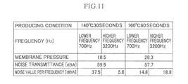
- FIG. 11 is a table showing a relation between a heating condition and frequency characteristics of the voice transmitter unit according to Embodiment 1.
- Embodiment 1 of the present invention is shown in FIG. 1 to FIG. 6 .
- a voice transmitter unit 10 of this Embodiment 1 is provided to a protective mask 110 as shown in FIG. 3 or a protective garment 120 as shown in FIG. 4 so as to transmit speech uttered by a wearer 100 who wears the protective mask 110 or the protective garment 120 to the outside.
- the voice transmitter unit 10 of this Embodiment 1 includes a voice transmitter body 11 , a cover member 14 , and a mounting base 15 .
- the voice transmitter body 11 of this Embodiment 1 includes a diaphragm member 12 and a holding member 13 .
- the diaphragm member 12 is formed of a heat-shrinkable material, such as a material of polypropylene and polyester.
- the diaphragm member 12 is made of the above material as a thick-film member, and is capable of transmitting speech from one side to the other side.
- the diaphragm member 12 is preferably formed to have a film thickness of approximately 0.01 to 0.2 mm. In this Embodiment 1, the diaphragm member 12 is formed to have a film thickness of approximately 0.05 mm.
- the diaphragm member 12 may be formed by using any material with any thickness as far as the material has a heat-shrinkable property, and can transmit speech uttered by the wearer 100 from one side (i.e., the inside of the voice transmitter unit 10 ) to the other side (i.e., the outside of the voice transmitter unit 10 ).
- An entire shape of the diaphragm member 12 is formed to be larger than an outer diameter of the holding member 13 .
- the shape of the diaphragm member 12 may be the same as an outer edge shape of the holding member 13 , but the present invention is not limited to the same shape as that of the holding member 13 .
- the holding member 13 is formed of resin having a high rigidity or the like.
- the holding member 13 is formed in a frame shape. Specifically, the holding member 13 is formed in a ring shape in this Embodiment 1.
- the voice transmitter body 11 is held between the cover member 14 and the mounting base 15 .
- the cover member 14 is formed by a member made of resin having a high rigidity or the like.
- a member body 16 of the cover member 14 is formed in a substantially cylindrical shape.
- the member body 16 has an inner diameter slightly larger than a diameter of the voice transmitter body 11 so that the voice transmitter body 11 can be housed in the member body 16 .
- a protective member 17 is disposed on one end side of the cover member 14 .
- the protective member 17 is formed by arranging plural stick-like members 17 a side by side.
- a gap 18 is formed between every two adjacent stick-like members 17 a .
- the above configuration of the protective member 17 attains both preferable voice transmission and damage prevention of the voice transmitter body 11 from external ballistic fragments. Any configuration (e.g., tiltingly arranging plural plate bodies side by side, making a grid form, or having a number of small holes) of the protective member 17 may be employed as far as the preferable speech transmission and the damage prevention of the voice transmitter body 11 can be both attained.
- Locking portions 19 are projectingly formed at a lower end of the member body 16 .
- An inwardly curved hook is provided at a front end of each locking portion 19 , and these hooks are locked to the mounting base 15 described later.
- the mounting base 15 is disposed on a front surface of the protective mask 110 or the protective garment 120 in use at a portion located closely to a front of the mouth of the wearer 100 .
- the mounting base 15 is formed of a high-rigidity resin or the like in a substantially ring shape.
- An outer diameter of the mounting base 15 is formed to be substantially the same as an outer diameter of the voice transmitter body 11 .
- the mounting base 15 may be joined to the protective mask 110 or the protective garment 120 , may be integrally formed with the protective mask 110 or the protective garment 120 , or may be formed to be detachable relative to the protective mask 110 or the protective garment 120 .
- the entire voice transmitter unit 10 may be joined to the protective mask 110 or the protective garment 120 , or may be integrally formed with the protective mask 110 or the protective garment 120 . Specifically, a part or whole of the voice transmitter unit 10 may be detachable to, or integrally formed with the protective mask 110 or the protective garment 120 .
- the protective mask 110 as shown in FIG. 3 is a gas mask, a dust respirator, an airline respirator, a respirator, or the like, and is used for protecting respiration of an operator from dusts, fine toxic substances such as asbestos, air polluted by a poisonous gas, harmful aerosol, microbes, or toxins.
- the voice transmitter unit 10 of this Embodiment is disposed to a portion of a mask main body 111 of the protective mask 110 corresponding to the front of the mouth of the wearer 100 when the wearer 100 wears the mask.
- the mask main body 111 is provided with a filter member 112 that filters dusts and toxic substances.
- any configuration may be employed for the protective mask 110 .
- a facepiece or the like of the protective mask 110 may be of a semi-half face type shown in FIG. 3 , a full face type, or a face shield type.
- An air intake mechanism of the protective mask 110 may be of a so-called air-feed type including a self-respirator, for example, other than a filtering type as shown in FIG. 3 .
- the protective garment 120 as shown in FIG. 4 may be a chemical protective garment, a ballistic-fragment protective garment, a fall protective garment, an electric-work protective garment, a radiation protective garment, a fire protective garment, a wasp-extermination protective garment, or an explosion protective garment, for example.
- FIG. 4 shows the protective garment 120 of a hood type covering the head to the shoulder of the wearer 100 . It should be noted that protective garments of other types may also be employed, as described later.
- a protective garment body 121 of the protective garment 120 is formed by using fabric made of a material impermeable to dusts or toxic substances. There is provided a transparent window 122 at a position of the protective garment body 121 corresponding to the eyes of the wearer 100 when the wearer 100 wears the protective garment.
- a central aperture 123 is formed in the protective garment 120 , and the mounting base 15 as well as the voice transmitter unit 10 are disposed to this central aperture 123 .
- Side apertures 124 are formed at both side portions relative to the central aperture 123 , and the filter member 112 is disposed to each of the side apertures 124 .
- the voice transmitter unit 10 and the filter member 112 are coupled to a mask 125 worn by the wearer 100 inside the protective garment body 121 . This configuration attains both respiration of the wearer 100 who wears the protective garment 120 and transmission of speech uttered by the wearer 100 to the outside.
- a listening unit 126 for allowing the wearer 100 in the protective garment 120 to readily listen to external sounds at a portion of the protective garment body 121 corresponding to each ear of the wearer 100 when the wearer 100 wears the garment.
- the listening unit 126 may be configured in the same manner as that of the voice transmitter unit 10 , thereby attaining reduction in cost of the protective garment 120 .
- the protective garment 120 may be configured in any manner.
- the protective garment 120 may be of a suit type that covers the entire body of the wearer 100 .
- a portion of the protective garment 120 corresponding to the face of the wearer 100 may be opened so as to expose the face (in a state of wearing the mask 125 ) of the wearer 100 to the outside.
- an air supply unit (not shown) that sends clean air to the inside of the protective garment 120 is provided so that it is unnecessary for the wearer 100 to wear the mask 125 inside the protective garment 120 .
- the diaphragm member 12 is disposed on one surface of the holding member 13 .
- the one surface of the holding member 13 is entirely covered with the diaphragm member 12 .
- a peripheral edge portion of the diaphragm member 12 is wrapped around a peripheral edge portion 13 a of the holding member 13 to the other surface thereof.
- the peripheral edge portion of the diaphragm member 12 is brought into a state of being wrapped around under a lower surface of the holding member 13 as shown in FIG. 2A .
- the diaphragm member 12 In this state, if the diaphragm member 12 is heated, the diaphragm member 12 becomes shrunk due to heat. At this time, the peripheral edge portion of the diaphragm member 12 (specifically, the portion wrapped around under the lower surface of the holding member 13 ) also becomes shrunk, thus generating a tensile force to pull the holding member 13 toward the inside. As a result, the diaphragm member 12 covers the holding member 13 while the tension is maintained, thereby holding the diaphragm member 12 by the holding member 13 . This tension maintains a portion of the diaphragm member 12 located on an upper surface of the holding member 13 to be in a state of having no wrinkles and no sagging. Through the above processing, the voice transmitter body 11 is completed.
- the wearer 100 houses the voice transmitter body 11 in the cover member 14 .
- the wearer 100 mounts the cover member 14 on the mounting base 15 of the protective mask 110 , and locks the hooks of the locking portions 19 to the mounting base 15 so as to hold the voice transmitter body 11 between the cover member 14 and the mounting base 15 .
- the voice transmitter unit 10 is mounted to the protective mask 110 .
- the wearer 100 places the protective mask 110 on which the voice transmitter unit 10 is mounted at a position of his or her mouth, and puts strings on the ears, thereby completing the wearing of the protective mask 110 . In this state, the wearer 100 can use the protective mask 110 .
- the cover member 14 in which the voice transmitter body 11 is housed is mounted on the mounting base 15 of the protective garment 120 , and the voice transmitter unit 10 is mounted on the protective garment 120 , and thereafter, the wearer 100 wears the protective garment 120 .
- the present inventors produced the holding members 13 of plural different types using various heating temperatures and various heating times.
- the present inventors measured transmission amounts of speech in a lower frequency region (700 Hz in this case) and a higher frequency region (3200 Hz in this case) for each of these holding members 13 .
- each diaphragm member 12 a region contributing to transmission of speech was defined to be a circular region having a diameter of 36 mm. This measurement was carried out using Sound Level Meter Class 1 NL-52 manufactured by RION Co., Ltd. as a measuring instrument in such a manner that speech at 70 [dB] was measured at a position as far as 1 m away from the speech for two minutes.
- FIG. 11 is a table showing part of measurement results.
- a tension applied to the diaphragm member 12 i.e., membrane pressure in FIG. 11
- a transmittance of the speech in entire frequency band was 59.9 [dBA].
- a transmittance of speech at 700 [Hz] was 37.5 [dBA]
- a transmittance of speech at 3200 [Hz] was 5.6 [dBA].
- a tension applied to the diaphragm member 12 was 28.3 [g/cm 2 ], and a transmittance of speech in the entire frequency band was 57.7 [dBA].
- a transmittance of speech at 700 [Hz] was 14.8 [dBA]
- a transmittance of speech at 3200 [Hz] was 18.8 [dBA].
- a value of the tension of the diaphragm member 12 could be adjusted by changing the heating temperature and the heating time. It was found that if the tension is smaller, the transmittance of speech in the lower frequency range became greater, and if the tension is greater, the transmittance of speech in the higher frequency range became greater.
- the diaphragm member 12 of the voice transmitter body 11 is formed of a heat-shrinkable material, and the diaphragm member 12 is heated to be shrunk while the diaphragm member 12 is held by the holding member 13 , thereby holding the diaphragm member 12 by the holding member while the substantially entire surface of the diaphragm member 12 is tensed; therefore, the diaphragm member 12 becomes shrunk only by heating the diaphragm member 12 while the diaphragm member 12 is held by the holding member 13 .
- the diaphragm member 12 can be held by the holding member 13 while the substantially entire area of the diaphragm member 12 is tensed by the holding member 13 , thus securely preventing generation of wrinkles and sagging of the diaphragm member 12 . Accordingly, it is possible to provide the voice transmitter body 11 and the voice transmitter unit 10 in a simple structure that can be manufactured at a low cost, and can make speech uttered by a wearer clearly hearable at the outside.
- the holding member 13 is formed to be a frame having a substantially circular shape in a front view or any shape
- the aperture formed on the inner side of the holding member 13 is covered with the diaphragm member
- the diaphragm member 12 is heated to be shrunk, thereby applying tension to the diaphragm member 12 in all directions around the circumference of the diaphragm member 12 .
- a degree of tension applied to the diaphragm member 12 can readily be adjusted by controlling at least one of the heating temperature and the heating time of the diaphragm member 12 , hence it is possible to easily adjust the frequency characteristics of the speech transmitted through this diaphragm member 12 .
- the voice transmitter unit 10 at a low cost, which is capable of easily transmitting speech to the outside by adjusting the tension of the diaphragm member 12 in accordance with the voice characteristics with a high accuracy.
- the holding member 13 in the voice transmitter body 11 of the voice transmitter unit 10 , is illustrated in a substantially ring shape in a front view, but the holding member 13 is not limited to this, and any shape may be employed as far as the holding member 13 is formed in a frame shape.
- the voice transmitter body 11 , the cover member 14 , and the mounting base 15 of the voice transmitter unit 10 are respectively formed in an approximately rectangular shape in a front view, and the holding member 13 of the voice transmitter body 11 is also formed in an annular form having a substantially rectangular shape in a front view.
- the diaphragm member 12 is also formed to be greater than the entire shape of the holding member 13 .
- the member body 16 of the cover member 14 is formed in a substantially square pole shape
- the mounting base 15 is formed in a substantially rectangular shape in plain view.
- the voice transmitter unit 10 may also be configured to respectively form the voice transmitter unit 10 , the cover member 14 , and the mounting base 15 in a shape including recessedly curved surfaces, such as a so-called gourd shape (shape defined by a pair of projectingly curved surfaces and a pair of recessedly curved surfaces) in a front view.
- a so-called gourd shape shape defined by a pair of projectingly curved surfaces and a pair of recessedly curved surfaces
- the voice transmitter body 11 , the cover member 14 , and the mounting base 15 may be formed in any substantially polygonal shape other than a rectangle shape in a front view, such as a substantially pentagon and a substantially hexagon, or may be formed in a shape including an assembly of straight lines and curved surfaces which partially include substantially recessed portions.
- the cover member 14 and the mounting base 15 may be formed into any solid bodies.
- the voice transmitter body 11 may be formed in a cone shape (recessed conical shape) or in a dome shape (swelling semi-spherical shape), and the cover member 14 and the mounting base 15 may be respectively formed in a recessed shape and a projecting shape corresponding to the shapes of the voice transmitter body 11 .
- the holding member 13 of the voice transmitter body 11 is formed as a frame in a cone shape or a dome shape, and the diaphragm member 12 is mounted on this frame, and is heat-shrunk, thereby forming the voice transmitter body 11 in a cone shape or a dome shape.
- the holding member 13 may be formed in any shape other than a frame shape as far as the diaphragm member 12 can be tensed in a state of having no wrinkles and no sagging while the diaphragm member 12 is firmly fixed.
- the holding member 13 may be formed in a substantially U shape with all corners in straight angles or a substantially U shape with round corners, or may be formed such that a pair of stick-like members are arranged in substantially parallel to each other in such a manner as to hold at least part of the diaphragm member 12 that is disposed on the inner side of the holding member 13 .
- the voice transmitter unit 10 it is possible to flexibly form the voice transmitter unit 10 into a shape suitable to the shapes or specifications of the protective mask 110 and the protective garment 120 , at the same time, in the voice transmitter body 11 , it is possible to readily prevent wrinkles and sagging in the diaphragm member 12 . It becomes more flexible to select respective shapes of the voice transmitter unit 10 and the voice transmitter body 11 , thus facilitating designing of the protective mask 110 and the protective garment 120 .
- FIG. 7 shows Embodiment 2 of the present invention.
- a voice transmitter body 21 instead of the voice transmitter body 11 of Embodiment 1.
- the voice transmitter body 21 includes a diaphragm member 22 and a pair of holding members 23 a , 23 b.
- the diaphragm member 22 of this Embodiment 2 as shown in FIG. 7 is formed in a substantially circular shape in a front view.
- the diameter of the diaphragm member 22 may be the same as the diameter (outer diameter) of each of the holding members 23 a , 23 b , or may be larger or smaller than the diameter of each of the holding members 23 a , 23 b .
- the diaphragm member 22 may be formed in any shape as far as the diaphragm member 22 is not smaller than the inner diameter of each of the holding members 23 a , 23 b.
- Each of the holding members 23 a , 23 b in this Embodiment 2 is formed to be a ring-shaped frame, and holds the diaphragm member 22 therebetween.
- Each of the holding members 23 a , 23 b may have the same diameter, or one of the members, for example, the holding member 23 a may have a larger diameter than that of the other member, for example, the holding member 23 b.
- the diaphragm member 22 in a fabricating process of the voice transmitter body 21 as shown in FIG. 7 , the diaphragm member 22 is disposed between the pair of holding members 23 a , 23 b .
- the diaphragm member 22 is held between the pair of holding members 23 a , 23 b , and is firmly fixed using a desired method, and thereafter, the diaphragm member 22 is heated to be tensed so that the diaphragm member 22 is held by the holding members 23 a , 23 b in a state of having no wrinkles and no sagging.
- the holding members 23 a , 23 b have different diameters from each other, a peripheral edge portion of the holding member having a greater diameter, for example, the holding member 23 a may be wrapped around the holding member having a smaller diameter, for example, the holding member 23 b with the diaphragm member 22 held between the holding members 23 a , 23 b , and in this state, the diaphragm member 22 may be held between the holding members 23 a , 23 b in the same manner as that of Embodiment 1.
- the diaphragm member 22 in the voice transmitter body 21 , can be held between the pair of holding members 23 a , 23 b so as to be strongly and firmly fixed, thus preventing separation of the diaphragm member 22 from the holding members 23 a , 23 b as well as readily producing the voice transmitter body 21 in a state in which the diaphragm member 22 has no wrinkles and no sagging.
- each of the holding members 23 a , 23 b may have a shape other than the substantially ring shape in a front view.
- FIG. 8 show Embodiment 3 of the present invention.
- a voice transmitter body 31 instead of the voice transmitter body 11 of Embodiment 1 and the voice transmitter body 21 of Embodiment 2, there is provided a voice transmitter body 31 .
- the voice transmitter body 31 includes a diaphragm member 32 , and a pair of holding members 33 a , 33 b .
- the diaphragm member 32 has the same configuration as that of the diaphragm member 22 of Embodiment 2.
- Each of the holding members 33 a , 33 b is formed to be a ring-shaped frame as similar to the holding members 23 a , 23 b of Embodiment 2, and holds the diaphragm member 32 therebetween.
- the holding members 33 a , 33 b are different from the holding members 23 a , 23 b of Embodiment 2 in that a folding portion 34 b is provided to a vicinity of a peripheral edge portion of the holding member 33 b .
- the folding portion 34 b is so formed as to wrappingly hold an outer edge portion of the holding member 33 a when the holding members 33 a , 33 b are stacked.
- the diaphragm member 32 in a fabricating process of the voice transmitter body 31 as shown in FIG. 8A , the diaphragm member 32 is disposed between the pair of holding members 33 a , 33 b .
- the diaphragm member 32 is held between the pair of holding members 33 a , 33 b , and the folding portion 34 b is folded around to the inner side (in the upper direction of the drawing indicated by arrows in FIG. 8A ) to be firmly fixed (see an enlarged view of FIG. 8B ).
- the diaphragm member 32 is heated to be tensed so that the diaphragm member 32 is held by the holding members 33 a , 33 b in a state of having no wrinkles and no sagging.
- the diaphragm member 32 in the voice transmitter body 31 , can be held between the pair of holding members 33 a , 33 b , and the folding portion 34 b can be so folded as to be strongly and firmly fixed, thus more securely preventing separation of the diaphragm member 32 from the holding members 33 a , 33 b as well as readily producing the voice transmitter body 31 including the diaphragm member 32 in a state of having no wrinkles and no sagging.
- each of the holding members 33 a , 33 b may have a shape other than the substantially ring shape in a front view.
- FIG. 9 shows Embodiment 4 of the present invention.
- a voice transmitter body 41 instead of the voice transmitter bodies 11 , 21 , 31 of Embodiments 1 to 3, there is provided a voice transmitter body 41 .
- the voice transmitter body 41 includes a diaphragm member 42 , and a pair of holding members 43 a , 43 b .
- the diaphragm member 42 has the same configuration as that of the diaphragm member 22 of Embodiment 2.
- Each of the holding members 43 a , 43 b is formed to be a ring-shaped frame as similar to the holding members 23 a , 23 b of Embodiment 2, and holds the diaphragm member 42 therebetween.
- the holding member 43 b is different from the holding member 23 b of Embodiment 2 in that a swaging projection 44 is provided on an inner side (upper side in FIG. 9 ) of the holding member 43 b.
- the diaphragm member 42 in a fabricating process of the voice transmitter body 41 as shown in FIG. 9 , the diaphragm member 42 is disposed between the pair of holding members 43 a , 43 b .
- the diaphragm member 42 is held between the pair of holding members 43 a , 43 b (see a state “before swaging” in an enlarged view of FIG. 9 ).
- the vicinities of peripheral edge portions of the holding members 43 a , 43 b are swaged with the diaphragm member 42 held therebetween, thereby enclosing a peripheral edge portion of the diaphragm member 42 and the peripheral edge portion of the holding member 43 b by the peripheral edge portion of the holding member 43 a so as to be firmly fixed (see a state “after swaging” in the enlarged view of FIG. 9 ).
- the diaphragm member 42 is put in a state of being tensed to some extent.
- the diaphragm member 42 is heated to be tensed so that the diaphragm member 42 is held in a state of having no wrinkles and no sagging by the holding members 43 a , 43 b.
- the diaphragm member 42 can be so held by the holding members 43 a , 43 b as to be strongly and firmly fixed, it is possible to more securely prevent separation of the diaphragm member 42 from the holding members 43 a , 43 b , and readily produce the voice transmitter body 41 including the diaphragm member 42 in a state of having no wrinkles and no sagging.
- each of the holding members 43 a , 43 b may have a shape other than the substantially ring shape in a front view.
- FIG. 10 shows Embodiment 5 of the present invention.
- a voice transmitter body 51 instead of the voice transmitter bodies 11 , 21 , 31 , 41 of Embodiments 1 to 4, there is provided a voice transmitter body 51 .
- the voice transmitter body 51 includes a diaphragm member 52 , and a pair of holding members 53 a , 53 b .
- the diaphragm member 52 has the same configuration as that of the diaphragm member 22 of Embodiment 2.
- Each of the holding members 53 a , 53 b is formed to be a ring-shaped frame as similar to the holding members 23 a , 23 b of Embodiment 2, and holds the diaphragm member 52 therebetween.
- the holding members 53 a , 53 b are different from the holding members 23 a , 23 b of Embodiment 2 in that a fitting projection 54 a is disposed on an inner side (lower side in FIG. 10 ) of the holding member 53 a , and a fitted recess 54 b is disposed on an inner side (upper side in FIG. 10 ) of the holding member 53 b , respectively.
- the fitting projection 54 a and the fitted recess 54 b are so provided at respective positions as to overlap each other when the holding members 53 a , 53 b are stacked.
- the diaphragm member 52 in a fabricating process of the voice transmitter body 51 as shown in FIG. 10 , the diaphragm member 52 is disposed between the pair of holding members 53 a , 53 b .
- the diaphragm member 52 is held between the pair of holding members 53 a , 53 b .
- the fitting projection 54 a of the holding member 53 a is fitted to the fitted recess 54 b in such a manner as to be firmly fixed to each other with the diaphragm member 52 held therebetween.
- the diaphragm member 52 is heated to be tensed so that the diaphragm member 52 is held in a state of having no wrinkles and no sagging by the holding members 53 a , 53 b.
- each of the holding members 53 a , 53 b may have a shape other than the substantially ring shape in a front view.
- the diaphragm member 12 is mounted on the holding member 13 , the diaphragm members 22 , 32 , 42 , 52 are respectively held by the holding members 23 a and 23 b , 33 a and 33 b , 43 a and 43 b , and 53 a and 53 b , and thereafter, the diaphragm members 12 , 22 , 32 , 42 , 52 are respectively heated to be shrunk.
- each of the diaphragm member 12 and the holding member 13 , the diaphragm member 22 and the holding members 23 a , 23 b , the diaphragm member 32 and the holding members 33 a , 33 b , the diaphragm member 42 and the holding members 43 a , 43 b , and the diaphragm member 52 and the holding members 53 a , 53 b is formed of a thermoplastic material such as polypropylene, the diaphragm member 12 and the holding member 13 , the diaphragm member 22 and the holding members 23 a , 23 b , the diaphragm member 32 and the holding members 33 a , 33 b , the diaphragm member 42 and the holding members 43 a , 43 b , and the diaphragm member 52 and the holding members 53 a , 53 b are firmly joined by welder processing or the like, respectively, and thereafter, each of the diaphragm member 12 and the holding member 13
Landscapes
- Health & Medical Sciences (AREA)
- Physics & Mathematics (AREA)
- Multimedia (AREA)
- Acoustics & Sound (AREA)
- Engineering & Computer Science (AREA)
- Business, Economics & Management (AREA)
- Emergency Management (AREA)
- General Health & Medical Sciences (AREA)
- Pulmonology (AREA)
- Respiratory Apparatuses And Protective Means (AREA)
- Details Of Audible-Bandwidth Transducers (AREA)
- Diaphragms For Electromechanical Transducers (AREA)
- Professional, Industrial, Or Sporting Protective Garments (AREA)
Applications Claiming Priority (5)
| Application Number | Priority Date | Filing Date | Title |
|---|---|---|---|
| JP2013-027642 | 2013-02-15 | ||
| JP2013027642 | 2013-02-15 | ||
| JP2014-019979 | 2014-02-05 | ||
| JP2014019979A JP5759032B2 (ja) | 2013-02-15 | 2014-02-05 | 伝声器 |
| PCT/JP2014/053139 WO2014126083A1 (ja) | 2013-02-15 | 2014-02-12 | 伝声器 |
Publications (2)
| Publication Number | Publication Date |
|---|---|
| US20160001109A1 US20160001109A1 (en) | 2016-01-07 |
| US9592410B2 true US9592410B2 (en) | 2017-03-14 |
Family
ID=51354083
Family Applications (1)
| Application Number | Title | Priority Date | Filing Date |
|---|---|---|---|
| US14/767,473 Active US9592410B2 (en) | 2013-02-15 | 2014-02-12 | Voice transmitter |
Country Status (6)
| Country | Link |
|---|---|
| US (1) | US9592410B2 (ja) |
| JP (1) | JP5759032B2 (ja) |
| KR (1) | KR102039533B1 (ja) |
| CN (1) | CN105073205B (ja) |
| MY (1) | MY184392A (ja) |
| WO (1) | WO2014126083A1 (ja) |
Cited By (1)
| Publication number | Priority date | Publication date | Assignee | Title |
|---|---|---|---|---|
| US20180000173A1 (en) * | 2016-06-29 | 2018-01-04 | Garry Tsaur | Mask With a Sound-transmitting Structure |
Families Citing this family (4)
| Publication number | Priority date | Publication date | Assignee | Title |
|---|---|---|---|---|
| US11273334B2 (en) * | 2015-10-22 | 2022-03-15 | Scott Technologies, Inc. | Respirator mask with voice transmittal feature |
| US10856591B2 (en) * | 2017-08-29 | 2020-12-08 | To2M Corporation | Breathable mask capable of transmitting sound |
| KR101953988B1 (ko) * | 2017-08-31 | 2019-03-04 | 프랭크 자우어 | 소리를 전달할 수 있는 통기성 마스크 |
| GB201808993D0 (en) * | 2018-06-01 | 2018-07-18 | Avon Polymer Prod Ltd | Speech diaphram module for a respirator mask |
Citations (14)
| Publication number | Priority date | Publication date | Assignee | Title |
|---|---|---|---|---|
| US1730227A (en) * | 1923-03-31 | 1929-10-01 | Lewis M Mcbride | Gas mask |
| US3109425A (en) * | 1960-03-04 | 1963-11-05 | Electric Storage Battery Co | Respirator speaking diaphragm and exhalation valve unit |
| US3124130A (en) * | 1964-03-10 | Respirator with speaking diaphragm | ||
| US3140754A (en) * | 1954-02-12 | 1964-07-14 | Armard V Motsinger | Gas mask speech transmission |
| US3834231A (en) * | 1973-04-17 | 1974-09-10 | Tokyo Toyo Rubber Ind Co Ltd | Flexible diaphragms for gas meter |
| US5038459A (en) * | 1987-03-04 | 1991-08-13 | Hosiden Electronics Co., Ltd. | Method of fabricating the diaphragm unit of a condenser microphone by electron beam welding |
| CA2134914A1 (en) | 1993-11-16 | 1995-05-17 | Sadashige Koba | Face mask with adjustable ear loops and method of manufacture |
| US5895537A (en) * | 1997-10-09 | 1999-04-20 | Campbell; Richard G. | Sonic welded gas mask and process |
| JP2000189529A (ja) | 1998-12-28 | 2000-07-11 | Koken Ltd | 面体取り付け用伝声器 |
| JP2001275187A (ja) | 2000-03-24 | 2001-10-05 | Nec Viewtechnology Ltd | 平面スピーカ |
| US6305370B1 (en) * | 1998-10-02 | 2001-10-23 | DRäGER SICHERHEITSTECHNIK GMBH | Voice transmitter for a breathing protective mask |
| JP2002027582A (ja) | 2000-07-03 | 2002-01-25 | Nec Viewtechnology Ltd | スピーカシステム |
| JP2002219185A (ja) | 2001-01-26 | 2002-08-06 | Koken Ltd | 防護マスク用伝声装置 |
| US7610670B2 (en) * | 2005-05-25 | 2009-11-03 | Kabushiki Kaisha Audio-Technica | Method for manufacturing a diaphragm assembly |
Family Cites Families (5)
| Publication number | Priority date | Publication date | Assignee | Title |
|---|---|---|---|---|
| JP3376329B2 (ja) * | 1999-10-22 | 2003-02-10 | エヌイーシービューテクノロジー株式会社 | 振動膜及び平面スピーカ |
| JP3408476B2 (ja) * | 1999-11-19 | 2003-05-19 | エヌイーシービューテクノロジー株式会社 | 平面スピーカシステム |
| JP3457596B2 (ja) * | 1999-11-19 | 2003-10-20 | Necビューテクノロジー株式会社 | Usb対応スピーカ駆動システム |
| CN101102622B (zh) * | 2006-07-07 | 2011-12-14 | 欧力天工股份有限公司 | 振动膜组装体的制造方法以及电容式传声器 |
| CN201410243Y (zh) * | 2009-06-09 | 2010-02-24 | 无锡市华信安全设备有限公司 | 带传声装置的防毒防尘半面罩 |
-
2014
- 2014-02-05 JP JP2014019979A patent/JP5759032B2/ja active Active
- 2014-02-12 CN CN201480009055.7A patent/CN105073205B/zh active Active
- 2014-02-12 KR KR1020157020519A patent/KR102039533B1/ko active IP Right Grant
- 2014-02-12 WO PCT/JP2014/053139 patent/WO2014126083A1/ja active Application Filing
- 2014-02-12 US US14/767,473 patent/US9592410B2/en active Active
- 2014-02-12 MY MYPI2015702612A patent/MY184392A/en unknown
Patent Citations (15)
| Publication number | Priority date | Publication date | Assignee | Title |
|---|---|---|---|---|
| US3124130A (en) * | 1964-03-10 | Respirator with speaking diaphragm | ||
| US1730227A (en) * | 1923-03-31 | 1929-10-01 | Lewis M Mcbride | Gas mask |
| US3140754A (en) * | 1954-02-12 | 1964-07-14 | Armard V Motsinger | Gas mask speech transmission |
| US3109425A (en) * | 1960-03-04 | 1963-11-05 | Electric Storage Battery Co | Respirator speaking diaphragm and exhalation valve unit |
| US3834231A (en) * | 1973-04-17 | 1974-09-10 | Tokyo Toyo Rubber Ind Co Ltd | Flexible diaphragms for gas meter |
| US5038459A (en) * | 1987-03-04 | 1991-08-13 | Hosiden Electronics Co., Ltd. | Method of fabricating the diaphragm unit of a condenser microphone by electron beam welding |
| CA2134914A1 (en) | 1993-11-16 | 1995-05-17 | Sadashige Koba | Face mask with adjustable ear loops and method of manufacture |
| JPH07185027A (ja) | 1993-11-16 | 1995-07-25 | Minnesota Mining & Mfg Co <3M> | 耳掛け付顔面マスクおよびその製造方法 |
| US5895537A (en) * | 1997-10-09 | 1999-04-20 | Campbell; Richard G. | Sonic welded gas mask and process |
| US6305370B1 (en) * | 1998-10-02 | 2001-10-23 | DRäGER SICHERHEITSTECHNIK GMBH | Voice transmitter for a breathing protective mask |
| JP2000189529A (ja) | 1998-12-28 | 2000-07-11 | Koken Ltd | 面体取り付け用伝声器 |
| JP2001275187A (ja) | 2000-03-24 | 2001-10-05 | Nec Viewtechnology Ltd | 平面スピーカ |
| JP2002027582A (ja) | 2000-07-03 | 2002-01-25 | Nec Viewtechnology Ltd | スピーカシステム |
| JP2002219185A (ja) | 2001-01-26 | 2002-08-06 | Koken Ltd | 防護マスク用伝声装置 |
| US7610670B2 (en) * | 2005-05-25 | 2009-11-03 | Kabushiki Kaisha Audio-Technica | Method for manufacturing a diaphragm assembly |
Non-Patent Citations (1)
| Title |
|---|
| International Search Report mailed Mar. 25, 2014 for corresponding International Patent Application No. PCT/JP2014/053139. |
Cited By (1)
| Publication number | Priority date | Publication date | Assignee | Title |
|---|---|---|---|---|
| US20180000173A1 (en) * | 2016-06-29 | 2018-01-04 | Garry Tsaur | Mask With a Sound-transmitting Structure |
Also Published As
| Publication number | Publication date |
|---|---|
| WO2014126083A1 (ja) | 2014-08-21 |
| KR102039533B1 (ko) | 2019-11-01 |
| KR20150120343A (ko) | 2015-10-27 |
| MY184392A (en) | 2021-04-01 |
| CN105073205B (zh) | 2017-12-08 |
| CN105073205A (zh) | 2015-11-18 |
| JP5759032B2 (ja) | 2015-08-05 |
| JP2014176634A (ja) | 2014-09-25 |
| US20160001109A1 (en) | 2016-01-07 |
Similar Documents
| Publication | Publication Date | Title |
|---|---|---|
| US9592410B2 (en) | Voice transmitter | |
| WO2014030643A1 (ja) | 防護服 | |
| KR101985567B1 (ko) | 착용이 용이하면서 김서림을 방지한 방진마스크 | |
| JP5062619B2 (ja) | 保護ヘッドギアシステム | |
| JP7426001B2 (ja) | 音声伝達機能を備えた呼吸用マスク | |
| EP0728403B1 (en) | Voice transmission adaptor assembly | |
| WO2018188598A1 (zh) | 一种空气净化装置面罩 | |
| US11865377B2 (en) | System and method for fit test and monitoring for respiratory products | |
| US20160059051A1 (en) | Air Purification Respirator Voice Amplifier | |
| KR101925525B1 (ko) | 확성 기능을 구비한 안면 마스크 | |
| US20230024861A1 (en) | Head Covering Device Providing Filtered Air | |
| EP1484087A1 (en) | A microphone adaptor for a respirator | |
| US20240024709A1 (en) | Breathing apparatus and method of communicating using breathing apparatus | |
| KR101692524B1 (ko) | 다기능 안전면체 | |
| JP2016092630A (ja) | 防護マスク | |
| KR102656412B1 (ko) | 화재대피용 방연마스크 | |
| US20230233886A1 (en) | Respirator | |
| CN114515398B (zh) | 一种防护面具通信装置 | |
| TWI715454B (zh) | 口罩 | |
| US20230285781A1 (en) | Modular Reusable Elastomeric Half-Face Respirator | |
| KR102361833B1 (ko) | 마스크가 결합된 산업용 두건 | |
| CN214074766U (zh) | 一种新型防毒面具 | |
| JP6150993B2 (ja) | 防護服 | |
| AU2004202336B2 (en) | Speaker for a communication apparatus | |
| RU2212261C1 (ru) | Респиратор |
Legal Events
| Date | Code | Title | Description |
|---|---|---|---|
| AS | Assignment |
Owner name: KOKEN LTD., JAPAN Free format text: ASSIGNMENT OF ASSIGNORS INTEREST;ASSIGNORS:KANNO, RYO;MATSUDA, SHOKO;REEL/FRAME:036316/0043 Effective date: 20150710 |
|
| STCF | Information on status: patent grant |
Free format text: PATENTED CASE |
|
| MAFP | Maintenance fee payment |
Free format text: PAYMENT OF MAINTENANCE FEE, 4TH YR, SMALL ENTITY (ORIGINAL EVENT CODE: M2551); ENTITY STATUS OF PATENT OWNER: SMALL ENTITY Year of fee payment: 4 |