US9545752B2 - Film-applying machine - Google Patents
Film-applying machine Download PDFInfo
- Publication number
- US9545752B2 US9545752B2 US14/452,521 US201414452521A US9545752B2 US 9545752 B2 US9545752 B2 US 9545752B2 US 201414452521 A US201414452521 A US 201414452521A US 9545752 B2 US9545752 B2 US 9545752B2
- Authority
- US
- United States
- Prior art keywords
- coupled
- film
- storage
- assembly
- applying machine
- Prior art date
- Legal status (The legal status is an assumption and is not a legal conclusion. Google has not performed a legal analysis and makes no representation as to the accuracy of the status listed.)
- Expired - Fee Related, expires
Links
Images


Classifications
-
- B—PERFORMING OPERATIONS; TRANSPORTING
- B29—WORKING OF PLASTICS; WORKING OF SUBSTANCES IN A PLASTIC STATE IN GENERAL
- B29C—SHAPING OR JOINING OF PLASTICS; SHAPING OF MATERIAL IN A PLASTIC STATE, NOT OTHERWISE PROVIDED FOR; AFTER-TREATMENT OF THE SHAPED PRODUCTS, e.g. REPAIRING
- B29C63/00—Lining or sheathing, i.e. applying preformed layers or sheathings of plastics; Apparatus therefor
- B29C63/0004—Component parts, details or accessories; Auxiliary operations
-
- B—PERFORMING OPERATIONS; TRANSPORTING
- B29—WORKING OF PLASTICS; WORKING OF SUBSTANCES IN A PLASTIC STATE IN GENERAL
- B29C—SHAPING OR JOINING OF PLASTICS; SHAPING OF MATERIAL IN A PLASTIC STATE, NOT OTHERWISE PROVIDED FOR; AFTER-TREATMENT OF THE SHAPED PRODUCTS, e.g. REPAIRING
- B29C65/00—Joining or sealing of preformed parts, e.g. welding of plastics materials; Apparatus therefor
- B29C65/78—Means for handling the parts to be joined, e.g. for making containers or hollow articles, e.g. means for handling sheets, plates, web-like materials, tubular articles, hollow articles or elements to be joined therewith; Means for discharging the joined articles from the joining apparatus
- B29C65/7841—Holding or clamping means for handling purposes
- B29C65/7847—Holding or clamping means for handling purposes using vacuum to hold at least one of the parts to be joined
-
- B—PERFORMING OPERATIONS; TRANSPORTING
- B65—CONVEYING; PACKING; STORING; HANDLING THIN OR FILAMENTARY MATERIAL
- B65B—MACHINES, APPARATUS OR DEVICES FOR, OR METHODS OF, PACKAGING ARTICLES OR MATERIALS; UNPACKING
- B65B33/00—Packaging articles by applying removable, e.g. strippable, coatings
- B65B33/02—Packaging small articles, e.g. spare parts for machines or engines
-
- B—PERFORMING OPERATIONS; TRANSPORTING
- B25—HAND TOOLS; PORTABLE POWER-DRIVEN TOOLS; MANIPULATORS
- B25B—TOOLS OR BENCH DEVICES NOT OTHERWISE PROVIDED FOR, FOR FASTENING, CONNECTING, DISENGAGING, OR HOLDING
- B25B11/00—Work holders not covered by any preceding group in the subclass, e.g. magnetic work holders, vacuum work holders
- B25B11/005—Vacuum work holders
-
- B—PERFORMING OPERATIONS; TRANSPORTING
- B65—CONVEYING; PACKING; STORING; HANDLING THIN OR FILAMENTARY MATERIAL
- B65B—MACHINES, APPARATUS OR DEVICES FOR, OR METHODS OF, PACKAGING ARTICLES OR MATERIALS; UNPACKING
- B65B61/00—Auxiliary devices, not otherwise provided for, for operating on sheets, blanks, webs, binding material, containers or packages
-
- B—PERFORMING OPERATIONS; TRANSPORTING
- B29—WORKING OF PLASTICS; WORKING OF SUBSTANCES IN A PLASTIC STATE IN GENERAL
- B29C—SHAPING OR JOINING OF PLASTICS; SHAPING OF MATERIAL IN A PLASTIC STATE, NOT OTHERWISE PROVIDED FOR; AFTER-TREATMENT OF THE SHAPED PRODUCTS, e.g. REPAIRING
- B29C63/00—Lining or sheathing, i.e. applying preformed layers or sheathings of plastics; Apparatus therefor
- B29C63/02—Lining or sheathing, i.e. applying preformed layers or sheathings of plastics; Apparatus therefor using sheet or web-like material
-
- B—PERFORMING OPERATIONS; TRANSPORTING
- B65—CONVEYING; PACKING; STORING; HANDLING THIN OR FILAMENTARY MATERIAL
- B65B—MACHINES, APPARATUS OR DEVICES FOR, OR METHODS OF, PACKAGING ARTICLES OR MATERIALS; UNPACKING
- B65B33/00—Packaging articles by applying removable, e.g. strippable, coatings
-
- Y—GENERAL TAGGING OF NEW TECHNOLOGICAL DEVELOPMENTS; GENERAL TAGGING OF CROSS-SECTIONAL TECHNOLOGIES SPANNING OVER SEVERAL SECTIONS OF THE IPC; TECHNICAL SUBJECTS COVERED BY FORMER USPC CROSS-REFERENCE ART COLLECTIONS [XRACs] AND DIGESTS
- Y10—TECHNICAL SUBJECTS COVERED BY FORMER USPC
- Y10T—TECHNICAL SUBJECTS COVERED BY FORMER US CLASSIFICATION
- Y10T156/00—Adhesive bonding and miscellaneous chemical manufacture
- Y10T156/17—Surface bonding means and/or assemblymeans with work feeding or handling means
- Y10T156/1702—For plural parts or plural areas of single part
- Y10T156/1744—Means bringing discrete articles into assembled relationship
- Y10T156/1776—Means separating articles from bulk source
- Y10T156/1778—Stacked sheet source
Definitions
- the present disclosure relates to film-applying machines to apply protective films.
- a surface of the electronic device can be coated with a piece of protective film.
- a film-applying machine can be used to apply the protective film.
- FIG. 1 is an isometric view of an embodiment of a film-applying machine including a application apparatus, a storage apparatus, and a peeling apparatus, the storage apparatus including a rolling mechanism.
- FIG. 2 is similar to FIG. 1 but viewed from another angle.
- FIG. 3 is an exploded isometric view of the application apparatus of the film-applying machine of FIG. 1 .
- FIG. 4 is an isometric view of the storage apparatus of the film-applying machine of FIG. 1 .
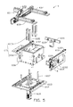
- FIG. 5 is an exploded isometric view of the storage apparatus of FIG. 4 .
- FIG. 6 is similar to FIG. 4 , but viewed from another angle.
- FIG. 7 is an exploded isometric view of the storage apparatus of FIG. 6 .
- FIG. 8 is an isometric view of the rolling mechanism of the storage apparatus of FIG. 4 .
- FIG. 9 is an isometric view of the peeling apparatus of the film-applying machine of FIG. 1 .
- Coupled is defined as connected, whether directly or indirectly through intervening components, and is not necessarily limited to physical connections.
- the connection can be such that the objects are permanently connected or releasably connected.
- substantially is defined to be essentially conforming to the particular dimension, shape, or other feature that the term modifies, such that the component need not be exact.
- substantially cylindrical means that the object resembles a cylinder, but can have one or more deviations from a true cylinder.
- comprising when utilized, means “including, but not necessarily limited to”; it specifically indicates open-ended inclusion or membership in the so-described combination, group, series and the like.
- a machine to apply a protective film can include a bracket, a mechanical arm adjacent to the bracket, an application apparatus coupled to the mechanical arm, a storage apparatus coupled to the bracket, and a controlling platform.
- the storage apparatus can include a storage mechanism, a driving mechanism, and a first rolling mechanism.
- the storage mechanism can include a supporting frame mounted to the bracket, and a storage assembly adjustably coupled to the supporting frame.
- the driving mechanism can include a supporting member and a driving assembly.
- the supporting member can be coupled to the supporting frame.
- the driving assembly can include a driving member coupled to the supporting member and a first transmission belt coupled to the driving member.
- the first rolling mechanism can include a pressing plate and a plurality of rollers. An end of the pressing plate can be coupled to the first transmission belt, and another end can be slidably coupled to the supporting frame.
- the plurality of rollers can be rotatably mounted on the pressing plate.
- the driving member can be configured to drive the first transmission belt and the first rolling assembly to slide relative to the storage assembly, such that the first rolling assembly can be configured to flatten a protective film supported on the storage assembly.
- the mechanical arm can be configured to drive the application apparatus to vacuum-lift a top layer
- the mechanical arm can be configured to drive the application apparatus to apply the top layer.
- the controlling platform can be electrically coupled to the mechanical arm, the application apparatus, and the storage apparatus, and can be configured to control the mechanical arm, the application apparatus, and the storage apparatus to cooperate to apply the protective film to the workpiece.
- FIGS. 1-2 illustrate an embodiment of a film-applying machine 10 which can be arranged beside a production line (not shown), and configured to apply a protective film 200 onto a workpiece (not shown) carried by the production line.
- the film-applying machine 10 can include a bracket 1 , a controlling platform 2 , a mechanical arm 3 , an application apparatus 4 , a storage apparatus 6 , and a peeling apparatus 8 (shown in FIG. 2 ).
- the bracket 1 can be disposed in a working environment.
- the controlling platform 2 can be mounted beside the bracket 1 .
- the mechanical arm 3 can be mounted on the bracket 1 and positioned adjacent to the controlling platform 2 .
- the application apparatus 4 can be mounted to an end of the mechanical arm 3 .
- the storage apparatus 6 can be mounted to the bracket 1 and positioned adjacent to the mechanical arm 3 .
- the peeling apparatus 8 can be mounted at a side of the storage apparatus 6 adjacent to the mechanical arm 3 .
- the controlling platform 2 having a built-in program, can be electrically coupled to the mechanical arm 3 , the application apparatus 4 , the storage apparatus 6 , and the peeling apparatus 8 .
- the controlling platform 2 can control the apparatuses mentioned above to cooperate with each other and complete a film-pasting process.
- the mechanical arm 3 can be a six-axis robot arm.
- the mechanical arm 3 can be mounted on other member, such as, but not limited to, the ground or a supporting frame (not shown).
- the mechanical arm 3 can be positioned adjacent to the storage apparatus 6 and configured to take a piece of the protective film 200 from the storage apparatus 6 onto the workpiece carried on the production line.
- the application apparatus 4 can be mounted to an end of the mechanical arm 3 and can be configured to vacuum-lift a protective film 200 and applying the protective film 200 onto a workpiece (not shown) carried by the production line.
- the application apparatus 4 can include a first mounting plate 41 , a cushion 43 , a second mounting plate 45 , and a sucking plate 47 .
- the first mounting plate 41 can be mounted to the mechanical arm 3 .
- a first end portion of the cushion 43 can be coupled to the first mounting plate 41 , and a second end portion can be coupled to the second mounting plate 45 .
- the cushion 43 can be elastic and configured to protect the workpiece from damage during the film-pasting process.
- the second mounting plate 45 can be substantially a rectangular plate.
- a plurality of connecting members 451 can be provided at a side of the second mounting plate 45 adjacent to the cushion 43 .
- Each connecting member 45 can define an inlet 4511 .
- the inlet 4511 can extend through the connecting member 451 and the second mounting plate 45 .
- a number of the connecting members 45 can be one or more than one.
- the connecting member 45 can be configured to couple with an external air-providing apparatus (not shown) to evacuate or generate gas.
- the sucking plate 47 can be mounted on another side of the second mounting plate 45 away from the connecting members 451 .
- the sucking plate 47 can be stacked up on the side of the second mounting plate 45 away from the cushions 43 .
- the sucking plate 47 can define a sunken portion 471 on a surface facing the second mounting plate 45 .
- the sunken portion 471 and the second mounting plate 45 can define a receiving cavity (not shown) for receiving gas.
- a bottom surface of the sunken portion 471 can define a plurality of holes 473 communicating with the sunken portion 471 .
- a plurality of sealing members 49 can be provided between the second mounting plate 45 and the sucking plate 47 .
- the sealing members 49 can surround edges of the sunken portion 471 .
- the inlet 4511 , the sunken portion 471 , and the holes 471 can define a gas channel, such that the application apparatus 4 can attract and lift the protective film 200 when gas is sucked from the holes 473 , the receiving cavity, and the connecting member 451 ; the application apparatus 4 can release the protective film 200 onto the workpiece when gas from the external air-providing apparatus is introduced to the holes 473 .
- the storage apparatus 6 can be mounted on the bracket 1 and positioned adjacent to the mechanical arm 3 .
- the storage apparatus 6 can be configured to store a plurality of multilayer protective film 200 .
- the storage apparatus 6 can include a storage mechanism 61 coupled to the bracket 1 and a rolling mechanism 63 mounted on the storage mechanism 61 .
- the storage mechanism 61 can include a supporting frame 611 , an adjusting assembly 613 , and a storage assembly 615 .
- the supporting frame 611 can include a basic plate 6112 , a movable plate 6113 , a first holder 6114 , a second holder 6115 , a third holder 6116 , and a guiding assembly 6117 .
- the basic plate 6112 can be substantially a rectangular plate and can be mounted to the bracket 1 .
- the movable plate 6113 can be substantially a rectangular plate and movably mounted to a side of the basic plate 6112 away from the bracket 1 .
- the movable plate 6113 can be positioned substantially on a middle of the base plate 6112 and configured to slide on the basic plate 6112 .
- the first holder 6114 can be mounted to the basic plate 6112 and can be substantially perpendicular to the basic plate 6112 .
- the first holder 6114 can provide a first rail 6101 at a side thereof away from the basic plate 6112 .
- a plurality of first sliding members 6103 can be slidably coupled to the first rail 6101 .
- the two first sliding members 6103 can be configured to slide along the first rail 6101 .
- the second holder 6115 can be mounted to the basic plate 6112 and coupled to the first holder 6114 .
- the second holder 6115 can be substantially perpendicular to the first holder 6114 and the basic plate 6112 .
- the third holder 6116 can be mounted on the basic plate 6112 and coupled to the second holder 6115 .
- the third holder 6116 can be substantially parallel to the first holder 6114 .
- the third holder 6116 can provide a second rail 6105 at a side thereof away from the basic plate 6112 .
- a plurality of second sliding members 6107 can be slidably coupled to the second rail 6105 . In the illustrated embodiment, there are two second sliding members 6107 .
- the two sliding members 6107 can be configured to slide along the second rail 6105 .
- the guiding assembly 6117 can be substantially perpendicularly mounted on the movable plate 6113 and positioned among the first holder 6114 , the second holder 6115 , and the third holder 6116 .
- the guiding assembly 6117 can include six guiding rods.
- a first guiding rod 6118 can be provided on a side of the first holder 6114 facing the guiding assembly 6117 .
- the first guiding rod 6118 can be substantially perpendicularly mounted on the first holder 6114 , to extend along a first direction parallel to the base plate 6112 and towards the guiding assembly 6117 .
- a second guiding rod 6119 can be provided on a side of the second holder 6115 adjacent to the guiding assembly 6117 .
- the second guiding rod 6119 can be substantially perpendicularly mounted on the second holder 6115 and extend along a second direction parallel to the base plate 6112 towards the guiding assembly 6117 .
- the second guiding rod 6119 can be substantially perpendicular to the first guiding rod 6118 .
- the guiding assembly 6117 , the first guiding rod 6118 , and the second guiding rod 6119 can be configured to cooperate with the adjusting assembly 613 to locate the storage apparatus 615 .
- the adjusting assembly 613 can include a lifting adjusting member 6131 , a first adjusting member 6133 , and a second adjusting member 6135 (shown in FIG. 6 ).
- the lifting adjusting member 6131 can be mounted to a side of the basic plate 6112 away from the guiding assembly 6117 .
- An end of the lifting adjusting member 6131 can extend through the basic plate 6112 and the movable plate 6113 to couple with the storage assembly 615 .
- the lifting adjusting member 6131 can be configured to adjust a height of the storage assembly 615 .
- the lifting adjusting member 6131 can be driven by a servo motor.
- the lifting adjusting member 6131 can uplift the storage assembly 615 appropriately.
- a top layer of the protective film 200 can be lifted, to enable the application apparatus 4 to vacuum-lift the top layer and further enable the rolling mechanism 63 to flatten the protective film 200 .
- the first adjusting member 6133 can be mounted on a side of the first holder 6114 away from the first guiding rod 6118 . An end of the first adjusting member 6133 can extend through the first holder 6114 and couple with the storage assembly 615 .
- the first adjusting member 6133 can be configured to adjust a location of the storage assembly 615 along the first direction.
- the second adjusting member 6135 can be mounted on a side of the second holder 6115 away from the second guiding rod 6119 . An end of the second adjusting member 6135 can extend through the second holder 6115 and couple with the storage assembly 615 .
- the second adjusting member 6135 can be configured to adjust a location of the storage assembly 615 along the second direction.
- the storage assembly 615 can include a storage member 6151 and a plurality of positioning members 6153 .
- the storage member 6151 can be movably mounted to the basic plate 6112 and positioned between the first holder 6114 and the second holder 6115 .
- the storage member 6151 can be configured to receive the multilayer protective film 200 .
- the storage member 6151 can be sleeved on the guiding assembly 6117 via a bottom surface thereof
- the storage member 6151 can be sleeved on the first guiding rod 6118 via a sidewall facing the first holder 6114 and sleeved on the second guiding rod 6119 via a sidewall facing the second holder 6115 .
- the storage member 6151 can be coupled to the lifting adjusting member 6131 , the first adjusting member 6133 , and the second adjusting member 6135 .
- the positioning member 6153 can be removably coupled to a side of the storage member 6151 away from the basic plate 6112 .
- the positioning member 6153 can be configured to precisely position the protective film 200 .
- the rolling mechanism 63 can be mounted at a side of the storage member 6151 away from the basic plate 6112 .
- the rolling mechanism 63 can be configured to flatten the protective film 200 and iron out any air bubbles between the sucking plate 47 and the protective film 200 , thereby improving a quality of film application process.
- the rolling mechanism 63 can include a supporting member 631 , a driving assembly 633 , a first rolling assembly 637 , and a second rolling assembly 639 .
- the supporting member 631 can be substantially a rectangular plate perpendicularly mounted to the third holder 6116 .
- the driving assembly 633 can include a driving member 6330 , a driver 6331 , a first transmission member 6332 , a second transmission member 6333 , a first follower 6334 , and a second follower 6335 .
- the driving member 6330 can be mounted to a side of the storage member 6151 away from the basic plate 6112 and positioned substantially on the middle of the storage member 6151 .
- the driving member 6330 can be a motor.
- the driver 6331 can be mounted to an end of the driving member 6330 adjacent to the supporting member 631 .
- the first transmission member 6332 can be mounted to a side of the supporting member 631 adjacent to the driving member 6330 and meshed with the driver 6331 .
- the second transmission member 6333 can be mounted to the supporting member 631 and meshed with the first transmission member 6332 .
- the driver 6331 , the first transmission member 6332 , and the second transmission member 6333 can be toothed gears.
- the first follower 6334 can be mounted to a side of the supporting member 631 away from the driving member 6330 .
- the first follower 6334 can include two first pulleys 6336 spaced from each other.
- a first transmission belt 6337 can be wound on the two first pulleys 6336 .
- One of the two first pulleys 6336 can be mounted to the supporting member 631 corresponding to the first transmission member 6332 and coupled to the first transmission member 6332 .
- Another first pulley 6336 can be mounted to an end of the supporting member 631 .
- the second follower 6335 can be mounted on the supporting member 631 and adjacent to the first follower 6334 .
- the second follower 6335 can include two second pulleys 6338 spaced from each other.
- a second transmission belt 6339 can be wound on the two second pulleys 6338 .
- One of the two second pulleys 6338 can be mounted to the supporting member 631 corresponding to the second transmission member 6333 and coupled to the second transmission member 6333 .
- Another second pulley 6338 can be mounted to an end of the supporting member 631 .
- the first transmission belt 6337 and the second transmission belt 6339 can be same-speed belts.
- the first rolling assembly 637 and the second rolling assembly 639 can be substantially parallel to each other and can be movably coupled to the first holder 6114 and the third holder 6116 .
- the first rolling assembly 637 can be coupled to the first transmission belt 6337
- the second rolling assembly 639 can be coupled to the second transmission belt 6339 .
- the driving member 6330 can move the transmission member 635 , such that the first assembly 637 and the second rolling assembly 639 can slide towards or away from each other along a direction parallel to the basic plate 6112 .
- the first rolling assembly 637 can correspond to the first follower 6334 and include a pressing plate 6371 , two bases 6373 , and a plurality of rollers 6375 .
- the pressing plate 6371 can be substantially a rectangular plate and positioned perpendicular to the supporting member 631 .
- An end of the pressing member 6371 can be coupled to one of the two second sliding members 6107 ; another end can extend towards the first holder 6114 and couple with one of the two first sliding members 603 .
- the bases 6373 can be mounted to opposite ends of the pressing plate 6371 .
- the plurality of the rollers 6375 can be substantially parallel to each other. Opposite ends of each roller 639 can be rotatably coupled to the bases 6373 .
- the second rolling assembly 639 can correspond to the second follower 6335 .
- a structure and a location of the second rolling assembly 639 can be similar to those of the first rolling assembly 637 .
- the second rolling assembly 639 can include a pressing plate, two bases, and a plurality of rollers. For the sake of simplicity, a description of the second rolling assembly 639 is omitted.
- the mechanical arm 3 can drive the application apparatus 4 and the piece of the multilayer protective film 200 on the application apparatus 4 to resist against the rollers 6375 and keep reciprocating relative to the rollers 6375 , such that air bubbles between the protective film 200 and the application apparatus 4 can be ironed out.
- the peeling apparatus 8 can be mounted on a side of the first holder 6114 adjacent to the mechanical arm 3 .
- the peeling apparatus 8 can be configured to peel off any backing paper adhering on the protective film 200 .
- the peeling apparatus 8 can be mounted on the bracket 1 and adjacent to the mechanical arm 3 such that the mechanical arm 3 can reach the peeling apparatus 8 .
- the peeling apparatus 8 can include a holding member 81 mounted on the first holder 6114 , a sucking member 83 mounted on the holding member 81 , and a sensor 85 mounted on the holding member 81 .
- the sucking member 83 can be substantially hollow.
- a gas nozzle 831 can be provided at an end of the sucking member 83 .
- the gas nozzle 831 can be a stack of flexible pieces. An end surface of the gas nozzle 831 can be substantially concave, such that the gas nozzle 831 can manipulate the backing paper without damaging the protective film 200 . When an end surface of the gas nozzle 831 is pressed, the gas nozzle 831 can be deformed, such that the backing paper can be attached on the gas nozzle 831 .
- the gas nozzle 831 can define a longitudinal through hole 8311 .
- the sensor 85 can be positioned adjacent to the gas nozzle 831 . When the sensor 85 senses that the mechanical arm 3 has driven the protective film 200 towards the gas nozzle 831 , the sucking member 83 can evacuate air.
- the backing paper protective film 200 can be firmly adhered on the gas nozzle 831 and the mechanical arm 3 can move the protective film 200 away from the peeling apparatus 8 , to leave the backing paper adhered on the gas nozzle 831 .
- the peeling apparatus 8 can be omitted, such that the backing paper can be peeled off by hand or by a robot.
- the multilayer protective film 200 can be stacked in the storage member 6151 via the positioning member 6153 , and then the positioning member 6153 can be removed from the storage member 6151 .
- the controller 2 can control the mechanical arm 3 and the application apparatus 4 to move close to the multilayer protective film 200 .
- the sucking plate 47 can resist against a top layer of the protective film 200 .
- the external air-providing apparatus can evacuate air via the application apparatus 4 , such that the top layer can be adhered onto the sucking plate 47 .
- the mechanical arm 3 can move the application apparatus 4 and the top layer of protective film 200 way from the storage member 6151 .
- the driving assembly 633 can drive the first rolling assembly 637 and the second rolling assembly 639 to slide towards each other and stop at the middle of the supporting member 631 , thereby flattening the multilayer protective film 200 on the storage member 6151 .
- the mechanical arm 3 can drive the application apparatus 4 and the top layer of protective film 200 to resist against the rollers 6375 and keep reciprocating relative to the rollers 6375 , such that air bubbles can be ironed out.
- the mechanical arm 3 can move the application apparatus 4 and the top layer close to the peeling apparatus 8 , the sucking member 83 can evacuate air, such that the backing paper of the top layer can be firmly adhered on the gas nozzle 831 , and the mechanical arm 3 can move the protective film away from the peeling apparatus 8 , leaving the release paper on the gas nozzle 831 .
- the mechanical arm 3 can drive the application apparatus 4 to apply the top layer of the protective film 200 onto the workpiece.
- the second rolling assembly 639 can be omitted; accordingly, the second transmission member 6333 and the second follower 6335 can be omitted.
- the two first pulleys 6336 can be mounted on opposite ends of the supporting member 631 , and the driving member 6330 , the driver 6331 , and the first transmission member 6332 can be mounted on one end of the supporting member 631 corresponding to one of the two pulleys 6336 .
Landscapes
- Engineering & Computer Science (AREA)
- Mechanical Engineering (AREA)
- Manufacturing & Machinery (AREA)
- Lining Or Joining Of Plastics Or The Like (AREA)
- Sheets, Magazines, And Separation Thereof (AREA)
- Container, Conveyance, Adherence, Positioning, Of Wafer (AREA)
- Physics & Mathematics (AREA)
- Fluid Mechanics (AREA)
Abstract
Description
Claims (20)
Applications Claiming Priority (2)
| Application Number | Priority Date | Filing Date | Title |
|---|---|---|---|
| CN201310338532.1A CN104340407B (en) | 2013-08-06 | 2013-08-06 | Automatic film sticking equipment |
| CN2013103385321 | 2013-08-06 |
Publications (2)
| Publication Number | Publication Date |
|---|---|
| US20150041065A1 US20150041065A1 (en) | 2015-02-12 |
| US9545752B2 true US9545752B2 (en) | 2017-01-17 |
Family
ID=52447582
Family Applications (1)
| Application Number | Title | Priority Date | Filing Date |
|---|---|---|---|
| US14/452,521 Expired - Fee Related US9545752B2 (en) | 2013-08-06 | 2014-08-05 | Film-applying machine |
Country Status (3)
| Country | Link |
|---|---|
| US (1) | US9545752B2 (en) |
| CN (1) | CN104340407B (en) |
| TW (1) | TW201522066A (en) |
Families Citing this family (41)
| Publication number | Priority date | Publication date | Assignee | Title |
|---|---|---|---|---|
| CN105984607A (en) * | 2015-03-04 | 2016-10-05 | 天津巨龙暖通设备开发有限公司 | Automatic film pasting device of heating radiator |
| CN104709504B (en) * | 2015-03-27 | 2017-02-01 | 广东韦达尔科技有限公司 | Full-automatic efficient film sticking machine |
| CN104960691B (en) * | 2015-06-05 | 2017-08-04 | 王艺 | A kind of sticking film for mobile phone device |
| CN105151385B (en) * | 2015-07-09 | 2016-05-18 | 濠玮电子科技(惠州)有限公司 | A kind of chain transmission type automatic film applicator and film coating process thereof |
| CN105083617B (en) * | 2015-08-14 | 2017-03-22 | 东莞市铭杨机械有限公司 | Full-automatic film sticking machine |
| CN107044470B (en) * | 2016-02-05 | 2019-06-18 | 康硕电子(苏州)有限公司 | Sticking device and sticking method for sticky workpiece |
| CN105819019B (en) * | 2016-05-17 | 2019-04-26 | 江苏杰士德精密工业有限公司 | Film adhering jig |
| EP3466644B1 (en) * | 2016-05-27 | 2023-07-05 | Lami Corporation Inc. | Laminating apparatus |
| CN106626349B (en) * | 2016-11-30 | 2018-12-21 | 深圳市三上高分子环保新材料股份有限公司 | Ultraviolet heating film covering method for packing tube |
| CN106672305A (en) * | 2017-02-28 | 2017-05-17 | 合肥宝亿自动化科技有限公司 | Frame automatic film pasting device and film pasting method thereof |
| CN107116880B (en) * | 2017-04-20 | 2019-05-17 | 浙江诚康钢管有限公司 | A kind of pressing machine |
| CN107264866A (en) * | 2017-07-31 | 2017-10-20 | 深圳市发斯特精密技术有限公司 | A kind of laminator and its method of work |
| CN109748136A (en) * | 2017-11-01 | 2019-05-14 | 湖南海擎智能科技有限责任公司 | Automatic coating scraping device |
| CN107972927A (en) * | 2017-12-21 | 2018-05-01 | 王荣华 | Tobacco finished product tape seal, which pushes away to smear attaching device and push away, smears the method for being adjacent to |
| CN108422675B (en) * | 2018-02-10 | 2019-09-13 | 泰州炬昕微电子有限公司 | A pre-aligned semi-automatic laminating machine |
| CN108891012A (en) * | 2018-06-27 | 2018-11-27 | 温州市科泓机器人科技有限公司 | Sticking film for mobile phone equipment towards flexible manufacturing |
| CN109263060B (en) * | 2018-08-14 | 2020-11-17 | 江苏明晶布业股份有限公司 | Multifunctional PTFE (Polytetrafluoroethylene) shaping and hot laminating equipment |
| CN109228299A (en) * | 2018-09-19 | 2019-01-18 | 深圳市嘉熠精密自动化科技有限公司 | A kind of vacuum laminator |
| CN109177144A (en) * | 2018-09-20 | 2019-01-11 | 东莞奥得时精密电子有限公司 | Waterproof breathable film structure material and process, and film laminating jig |
| CN109049669B (en) * | 2018-09-29 | 2024-02-13 | 苏州宏瑞达新能源装备有限公司 | A soft film laying support device |
| CN109335082B (en) * | 2018-10-05 | 2024-05-03 | 宣恩县璟泰电子有限公司 | Protective film pasting device and precious production facility that charges thereof |
| CN109353872A (en) * | 2018-10-25 | 2019-02-19 | 惠州市浩明科技股份有限公司 | Anti-scratch protective film feeding mechanism and slitting equipment |
| CN109436424B (en) * | 2018-11-09 | 2024-03-26 | 山东红宝自动化有限公司 | Automatic assembly line for display screen |
| CN109623732B (en) * | 2019-01-30 | 2023-12-15 | 领胜城科技(江苏)有限公司 | Automatic keyboard glue product assembling equipment and assembling process using same |
| CN109895369B (en) * | 2019-03-12 | 2025-03-11 | 东莞市驰卡实业有限公司 | Certificate film assembly mechanism and certificate making machine |
| CN110370612B (en) * | 2019-08-01 | 2022-04-19 | 圣杰智能科技(广州)有限公司 | Automatic film pasting method |
| CN112477092B (en) * | 2019-09-12 | 2022-10-14 | 福州康派克光电科技有限公司 | Vacuum self-adsorption box forming device and forming method |
| CN110712362B (en) * | 2019-09-24 | 2022-02-18 | 神通科技集团股份有限公司 | Automatic film pasting equipment and film pasting method thereof |
| CN110884714B (en) * | 2019-10-23 | 2021-09-17 | 广东金弘达自动化科技股份有限公司 | Packaging equipment for automatically wrapping and packaging flat plate products with thin films |
| CN110936600B (en) * | 2019-12-13 | 2020-10-02 | 荣旗工业科技(苏州)股份有限公司 | Automatic film pasting and assembling machine for blue film crescent moon gum |
| CN111086228A (en) * | 2019-12-27 | 2020-05-01 | 苏州领裕电子科技有限公司 | A rolling sticking suction device for keyboard glue |
| US12030266B2 (en) * | 2020-03-13 | 2024-07-09 | The Boeing Company | Scrolls that vacuum secure objects to complex surfaces |
| CN111844713B (en) * | 2020-07-07 | 2021-09-14 | 广州众人环保工程有限公司 | Auxiliary fixing device for automobile film and using method thereof |
| CN111731555A (en) * | 2020-07-17 | 2020-10-02 | 宁波峰梅新能源汽车科技有限公司 | An automatic plane laminating equipment |
| CN113334755B (en) * | 2021-04-19 | 2023-12-22 | 嘉兴思艺旅游用品有限公司 | ABS composite board thinning and film pressing device for draw-bar box |
| CN115367190B (en) * | 2021-09-10 | 2023-10-31 | 广东聚华印刷显示技术有限公司 | Film attaching device, film attaching equipment and film attaching method |
| CN114229571B (en) * | 2021-12-31 | 2023-12-12 | 深圳市联星服装辅料有限公司 | Belt arranging machine with cloth belt flattening function |
| CN115196085B (en) * | 2022-07-14 | 2023-05-26 | 上海中侨职业技术大学 | Packaging device for VR products |
| CN115535350B (en) * | 2022-09-30 | 2025-09-02 | 无锡中卓智能科技股份有限公司 | A high-efficiency film stripping machine for car lights |
| CN116834268B (en) * | 2023-07-10 | 2024-06-14 | 江苏联成开拓集团有限公司 | Automobile central control screen production film pasting device |
| CN118850428B (en) * | 2024-06-27 | 2025-09-16 | 歌尔股份有限公司 | Film pasting mechanical arm and film pasting equipment |
Citations (3)
| Publication number | Priority date | Publication date | Assignee | Title |
|---|---|---|---|---|
| US4293365A (en) * | 1980-08-01 | 1981-10-06 | Crown Zellerbach Corporation | Apparatus for applying labels or the like |
| CN202098569U (en) | 2011-06-01 | 2012-01-04 | 何忠亮 | Automatic laminator |
| US20140020843A1 (en) * | 2012-07-20 | 2014-01-23 | Hon Hai Precision Industry Co., Ltd. | Machine for cutting object and sticking film |
Family Cites Families (6)
| Publication number | Priority date | Publication date | Assignee | Title |
|---|---|---|---|---|
| JPH1034476A (en) * | 1996-07-18 | 1998-02-10 | Nec Eng Ltd | Sheet sticking device |
| DE10218347A1 (en) * | 2002-04-25 | 2003-11-06 | Nordson Corp | Protective layer application onto products, particularly furniture, involves deposition of one or more hot melt strips or beads onto product edges |
| CN2703384Y (en) * | 2004-05-17 | 2005-06-01 | 志圣科技(广州)有限公司 | Secondary rolling device for film press |
| CN102173316B (en) * | 2010-12-21 | 2013-06-19 | 上海技美电子科技有限公司 | Film sticking method and equipment |
| CN202743512U (en) * | 2012-06-26 | 2013-02-20 | 厦门市泽睿自动化科技有限公司 | Mulch applicator |
| CN202754169U (en) * | 2012-08-16 | 2013-02-27 | 深圳市创信力自动化设备有限公司 | Automatic sticking film machine |
-
2013
- 2013-08-06 CN CN201310338532.1A patent/CN104340407B/en not_active Expired - Fee Related
- 2013-08-09 TW TW102128595A patent/TW201522066A/en unknown
-
2014
- 2014-08-05 US US14/452,521 patent/US9545752B2/en not_active Expired - Fee Related
Patent Citations (3)
| Publication number | Priority date | Publication date | Assignee | Title |
|---|---|---|---|---|
| US4293365A (en) * | 1980-08-01 | 1981-10-06 | Crown Zellerbach Corporation | Apparatus for applying labels or the like |
| CN202098569U (en) | 2011-06-01 | 2012-01-04 | 何忠亮 | Automatic laminator |
| US20140020843A1 (en) * | 2012-07-20 | 2014-01-23 | Hon Hai Precision Industry Co., Ltd. | Machine for cutting object and sticking film |
Also Published As
| Publication number | Publication date |
|---|---|
| CN104340407A (en) | 2015-02-11 |
| CN104340407B (en) | 2016-08-10 |
| US20150041065A1 (en) | 2015-02-12 |
| TW201522066A (en) | 2015-06-16 |
Similar Documents
| Publication | Publication Date | Title |
|---|---|---|
| US9545752B2 (en) | Film-applying machine | |
| CN106043799B (en) | Automatic film pasting device and film pasting method for side surface periphery profiling | |
| CN111699056B (en) | Automatic feeding and discharging device and method of vision-based punching machine and punching equipment | |
| CN109573158B (en) | Lithium battery film sticking machine | |
| WO2013063847A1 (en) | Fully automated punching mechanical hand | |
| JP2020512195A (en) | Centering device | |
| CN110451003A (en) | Automatic laminating machine utilizing | |
| JP6336369B2 (en) | Cover glass laminating equipment | |
| CN113247351A (en) | Screen glass film pasting overturning device and method and film pasting equipment | |
| WO2013128710A1 (en) | Coating application device, substrate retaining device, and substrate retaining method | |
| KR102147127B1 (en) | Apparatus for cutting substrate | |
| KR20190059570A (en) | Apparatus for cutting substrate | |
| JP5177909B2 (en) | Board bonding equipment | |
| JP2014217851A (en) | Method for folding workpiece using press brake and press brake | |
| CN110931398B (en) | A packaging device | |
| KR101144978B1 (en) | Protective film attaching apparatus | |
| US20180071771A1 (en) | Detaching apparatus and detaching method | |
| CN212313007U (en) | Film tearing device | |
| TWM503060U (en) | Frame releasing mechanism of frame clamping jig and plate receiving and placing device thereof | |
| KR101969555B1 (en) | Apparatus and method for ejecting a semiconductor chip | |
| KR20100116573A (en) | Glass side tape attachment tape attachment device | |
| JP2016181613A (en) | Adhesive tape affixing device to substrate and affixing method | |
| JP6940267B2 (en) | Screen printing machine | |
| CN210557912U (en) | Automatic feeding positioning machine | |
| KR102114031B1 (en) | Apparatus for cutting substrate |
Legal Events
| Date | Code | Title | Description |
|---|---|---|---|
| AS | Assignment |
Owner name: HON HAI PRECISION INDUSTRY CO., LTD., TAIWAN Free format text: ASSIGNMENT OF ASSIGNORS INTEREST;ASSIGNORS:YANG, MING-LU;NI, JIE;SIGNING DATES FROM 20140804 TO 20140805;REEL/FRAME:033470/0410 Owner name: FU DING ELECTRONICAL TECHNOLOGY (JIASHAN) CO.,LTD. Free format text: ASSIGNMENT OF ASSIGNORS INTEREST;ASSIGNORS:YANG, MING-LU;NI, JIE;SIGNING DATES FROM 20140804 TO 20140805;REEL/FRAME:033470/0410 |
|
| STCF | Information on status: patent grant |
Free format text: PATENTED CASE |
|
| MAFP | Maintenance fee payment |
Free format text: PAYMENT OF MAINTENANCE FEE, 4TH YEAR, LARGE ENTITY (ORIGINAL EVENT CODE: M1551); ENTITY STATUS OF PATENT OWNER: LARGE ENTITY Year of fee payment: 4 |
|
| FEPP | Fee payment procedure |
Free format text: MAINTENANCE FEE REMINDER MAILED (ORIGINAL EVENT CODE: REM.); ENTITY STATUS OF PATENT OWNER: LARGE ENTITY |
|
| LAPS | Lapse for failure to pay maintenance fees |
Free format text: PATENT EXPIRED FOR FAILURE TO PAY MAINTENANCE FEES (ORIGINAL EVENT CODE: EXP.); ENTITY STATUS OF PATENT OWNER: LARGE ENTITY |
|
| STCH | Information on status: patent discontinuation |
Free format text: PATENT EXPIRED DUE TO NONPAYMENT OF MAINTENANCE FEES UNDER 37 CFR 1.362 |
|
| FP | Lapsed due to failure to pay maintenance fee |
Effective date: 20250117 |