US9523920B2 - Exposure device and exposure method - Google Patents

Exposure device and exposure method Download PDF

Info

Publication number
US9523920B2
US9523920B2 US14/386,245 US201314386245A US9523920B2 US 9523920 B2 US9523920 B2 US 9523920B2 US 201314386245 A US201314386245 A US 201314386245A US 9523920 B2 US9523920 B2 US 9523920B2
Authority
US
United States
Prior art keywords
marking
guide rail
exposure
rail frame
mask plate
Prior art date
Legal status (The legal status is an assumption and is not a legal conclusion. Google has not performed a legal analysis and makes no representation as to the accuracy of the status listed.)
Expired - Fee Related, expires
Application number
US14/386,245
Other versions
US20160238940A1 (en
Inventor
Haitao MA
Haisheng Zhao
Current Assignee (The listed assignees may be inaccurate. Google has not performed a legal analysis and makes no representation or warranty as to the accuracy of the list.)
BOE Technology Group Co Ltd
Beijing BOE Optoelectronics Technology Co Ltd
Original Assignee
BOE Technology Group Co Ltd
Beijing BOE Optoelectronics Technology Co Ltd
Priority date (The priority date is an assumption and is not a legal conclusion. Google has not performed a legal analysis and makes no representation as to the accuracy of the date listed.)
Filing date
Publication date
Application filed by BOE Technology Group Co Ltd, Beijing BOE Optoelectronics Technology Co Ltd filed Critical BOE Technology Group Co Ltd
Assigned to BEIJING BOE OPTOELECTRONICS TECHNOLOGY CO., LTD., BOE TECHNOLOGY GROUP CO., LTD. reassignment BEIJING BOE OPTOELECTRONICS TECHNOLOGY CO., LTD. ASSIGNMENT OF ASSIGNORS INTEREST (SEE DOCUMENT FOR DETAILS). Assignors: MA, HAITAO, ZHAO, Haisheng
Publication of US20160238940A1 publication Critical patent/US20160238940A1/en
Application granted granted Critical
Publication of US9523920B2 publication Critical patent/US9523920B2/en
Expired - Fee Related legal-status Critical Current
Adjusted expiration legal-status Critical

Links

Images

Classifications

    • GPHYSICS
    • G03PHOTOGRAPHY; CINEMATOGRAPHY; ANALOGOUS TECHNIQUES USING WAVES OTHER THAN OPTICAL WAVES; ELECTROGRAPHY; HOLOGRAPHY
    • G03FPHOTOMECHANICAL PRODUCTION OF TEXTURED OR PATTERNED SURFACES, e.g. FOR PRINTING, FOR PROCESSING OF SEMICONDUCTOR DEVICES; MATERIALS THEREFOR; ORIGINALS THEREFOR; APPARATUS SPECIALLY ADAPTED THEREFOR
    • G03F7/00Photomechanical, e.g. photolithographic, production of textured or patterned surfaces, e.g. printing surfaces; Materials therefor, e.g. comprising photoresists; Apparatus specially adapted therefor
    • G03F7/70Microphotolithographic exposure; Apparatus therefor
    • G03F7/70483Information management; Active and passive control; Testing; Wafer monitoring, e.g. pattern monitoring
    • G03F7/70491Information management, e.g. software; Active and passive control, e.g. details of controlling exposure processes or exposure tool monitoring processes
    • G03F7/70541Tagging, i.e. hardware or software tagging of features or components, e.g. using tagging scripts or tagging identifier codes for identification of chips, shots or wafers
    • GPHYSICS
    • G03PHOTOGRAPHY; CINEMATOGRAPHY; ANALOGOUS TECHNIQUES USING WAVES OTHER THAN OPTICAL WAVES; ELECTROGRAPHY; HOLOGRAPHY
    • G03FPHOTOMECHANICAL PRODUCTION OF TEXTURED OR PATTERNED SURFACES, e.g. FOR PRINTING, FOR PROCESSING OF SEMICONDUCTOR DEVICES; MATERIALS THEREFOR; ORIGINALS THEREFOR; APPARATUS SPECIALLY ADAPTED THEREFOR
    • G03F7/00Photomechanical, e.g. photolithographic, production of textured or patterned surfaces, e.g. printing surfaces; Materials therefor, e.g. comprising photoresists; Apparatus specially adapted therefor
    • G03F7/20Exposure; Apparatus therefor
    • G03F7/2045Exposure; Apparatus therefor using originals with apertures, e.g. stencil exposure masks
    • GPHYSICS
    • G03PHOTOGRAPHY; CINEMATOGRAPHY; ANALOGOUS TECHNIQUES USING WAVES OTHER THAN OPTICAL WAVES; ELECTROGRAPHY; HOLOGRAPHY
    • G03FPHOTOMECHANICAL PRODUCTION OF TEXTURED OR PATTERNED SURFACES, e.g. FOR PRINTING, FOR PROCESSING OF SEMICONDUCTOR DEVICES; MATERIALS THEREFOR; ORIGINALS THEREFOR; APPARATUS SPECIALLY ADAPTED THEREFOR
    • G03F7/00Photomechanical, e.g. photolithographic, production of textured or patterned surfaces, e.g. printing surfaces; Materials therefor, e.g. comprising photoresists; Apparatus specially adapted therefor
    • G03F7/70Microphotolithographic exposure; Apparatus therefor
    • G03F7/70691Handling of masks or workpieces
    • G03F7/70716Stages
    • GPHYSICS
    • G03PHOTOGRAPHY; CINEMATOGRAPHY; ANALOGOUS TECHNIQUES USING WAVES OTHER THAN OPTICAL WAVES; ELECTROGRAPHY; HOLOGRAPHY
    • G03FPHOTOMECHANICAL PRODUCTION OF TEXTURED OR PATTERNED SURFACES, e.g. FOR PRINTING, FOR PROCESSING OF SEMICONDUCTOR DEVICES; MATERIALS THEREFOR; ORIGINALS THEREFOR; APPARATUS SPECIALLY ADAPTED THEREFOR
    • G03F7/00Photomechanical, e.g. photolithographic, production of textured or patterned surfaces, e.g. printing surfaces; Materials therefor, e.g. comprising photoresists; Apparatus specially adapted therefor
    • G03F7/70Microphotolithographic exposure; Apparatus therefor
    • G03F7/70691Handling of masks or workpieces
    • G03F7/70733Handling masks and workpieces, e.g. exchange of workpiece or mask, transport of workpiece or mask

Definitions

  • Embodiments of the present invention relate to an exposure device and an exposure method.
  • exposure of the circuit pattern and exposure of the identification pattern are carried out separately, and exposure of the identification pattern is conducted in such a way that exposure of the identification pattern is conducted on every product on the substrate one by one. This may lead to a too long time with the exposure process, and the production capacity is seriously affected.
  • an exposure device comprising: an exposure lamp, a mask plate and a marking equipment, the marking equipment comprising:
  • a guide rail frame disposed on the mask plate
  • At least one marking vehicle disposed on the guide rail frame
  • a controller configured to control the guide rail frame move to a corresponding exposure location on the mask plate earlier than the exposure lamp, and to control the marking vehicle lie in a corresponding marking location, for displaying a corresponding marking identification.
  • the marking vehicle is a mask for forming an identification pattern.
  • the marking vehicle includes a body module and a display panel module assembled together;
  • the display panel module includes: an identification display zone and a transmissive buffer zone that is located between the body module and the identification display zone;
  • the identification display zone acts to display the corresponding marking identification when the marking vehicle lies in the corresponding marking location
  • the transmissive buffer zone acts to conduct a transmissive display.
  • the controller acts to control the identification display zone of the marking vehicle to perform a transmissive display, and meanwhile to control the guide rail frame start to move, so that the guide rail frame moves to a second exposure location on the mask plate earlier than the exposure lamp.
  • a moving speed of the exposure lamp upon the mask plate being exposed with it is in a range of 0.2 to 0.3 m/s
  • a moving speed of the guide rail frame under the control of the controller is in a range of 3.0 to 6.0 m/s.
  • both the guide rail frame and the marking vehicle are provided with infrared detectors, which are used to detect locations of the marking vehicle and the guide rail frame on the mask plate.
  • the controller acts to receive location of the guide rail frame on the mask plate detected by the infrared detectors by a wireless transmission technology, to control the guide rail frame move to the corresponding exposure location on the mask plate, next, to receive location of the marking vehicle on the mask plate detected by the infrared detectors by the wireless transmission technology, and further to send a control signal to the marking vehicle by the wireless transmission technology to control the marking vehicle move to the corresponding marking location, so as to display the corresponding marking identification.
  • the device further comprises a linear motor
  • the linear motor is connected to the guide rail frame, and acts to drive the guide rail frame to move linearly along a direction perpendicular to the guide rail frame on the mask plate;
  • the controller acts to take control of movement of the guide rail frame by controlling the linear motor.
  • the exposure machine is configured to conduct a row-by-row exposure on the mask plate, the direction in which the guide rail moves is perpendicular to a row direction, and the guide rail is configured to be able to control the marking vehicle move in the row direction.
  • the exposure lamp, the marking vehicle and the mask plate are arranged sequentially in this order.
  • a portion of the mask plate corresponding to a place in need of marking is pervious to light.
  • Another embodiment of the invention provides an exposure method with the exposure device claimed as claim 1 , comprising the following steps:
  • the marking vehicle includes a body module and a display panel module assembled together;
  • the display panel module includes: an identification display zone and a transmissive buffer zone that is located between the body module and the identification display zone; wherein, the identification display zone acts to display the corresponding marking identification when the marking vehicle lies in the corresponding marking location; the transmissive buffer zone acts to conduct a transmissive display;
  • making the guide rail frame move to the corresponding exposure location on the mask plate earlier than the exposure lamp under the control of the controller and making the marking vehicle lie in the corresponding marking location under the control of the controller so as to display the corresponding marking identification includes:
  • a moving speed of the exposure lamp upon the mask plate being exposed with it is in a range of 0.2 to 0.3 m/s
  • a moving speed of the guide rail frame under the control of the controller is in a range of 3.0 to 6.0 m/s.
  • both the guide rail frame and the marking vehicle are provided with infrared detectors, which are used to detect locations of the marking vehicle and the guide rail frame on the mask plate; and making the marking vehicle lie in a corresponding marking location under the control of the controller so as to display the corresponding marking identification includes:
  • the device further comprises a linear motor; the linear motor is connected to the guide rail frame, and acts to drive the guide rail frame to move linearly along a direction perpendicular to the guide rail frame on the mask plate; and the control over the movement of the guide rail frame with the controller includes:
  • a controller is employed to make the guide rail frame move to a corresponding exposure location on the mask plate earlier than the exposure lamp under its control, and to make the marking vehicle lie in a corresponding marking location under its control to display a corresponding marking identification, waiting for the exposure lamp to move to the exposure location, so as to accomplish exposure of an identification pattern at the exposure location.
  • exposure is also conducted at identifying locations on the mask plate, so as to accomplish exposure of identification patterns.
  • FIG. 1 is a structurally schematic view illustrating an exposure device provided by an embodiment of the invention
  • FIG. 2 is a structurally schematic view illustrating a marking vehicle provided by an embodiment of the invention
  • FIG. 3 is a schematic view illustrating movement of a marking vehicle during an exposure provided by an embodiment of the invention.
  • the exposure device comprises an exposure lamp 1 , a mask plate 2 and a marking equipment 3 .
  • the marking equipment 3 includes: a guide rail frame 31 , disposed on the mask plate 2 ; at least one marking vehicle 32 , disposed on the guide rail frame 31 ; and a controller 34 , for controlling the guide rail frame 31 to move to a corresponding exposure location on the mask plate 2 earlier than the exposure lamp 1 , and for controlling the marking vehicle 32 move to a corresponding marking location, so as to display a corresponding marking identification.
  • the exposure location and the marking location on the mask plate 2 are fixed, and the exposure lamp 1 is a linear light source, and carries out a horizontal movement relative to the mask plate 1 , so as to conduct exposure operations row by row.
  • the exposure location refers to a position in one row on the mask plate 1 where identification patterns need to emerge by exposure
  • the marking location refers to a position in correspondence with each identification pattern that needs to emerge by exposure at the exposure location. So, preferably, the number of marking vehicles on the guide rail frame is the number of marking locations contained in one row on the mask plate.
  • marking locations at individual exposure locations are the same, and after the marking vehicle is moved to a corresponding marking location at a first exposure location, at the next exposure location, it is unnecessary for the controller to control the marking vehicle again for its movement.
  • the controller makes the guide rail frame move to the next exposure location on the mask plate earlier than the exposure lamp under its control, it also needs to make the marking vehicle move to a corresponding marking location under its control.
  • the exposure machine is configured to conduct a row-by-row exposure on the mask plate, the direction in which the guide rail moves is perpendicular to a row direction, and the guide rail is configured to be able to make the marking vehicle move in the row direction under its control.
  • the exposure lamp 1 moves horizontally to conduct a row-by-row exposure on the mask plate 2
  • the controller 34 controls the guide rail frame 31 to move to a corresponding exposure location on the mask plate 2 earlier than the exposure lamp 1 .
  • the exposure lamp moves to a corresponding exposure location where the guide rail frame 1 is located
  • exposure of an identification pattern can be completed.
  • the guide rail frame 31 will move to the next exposure location under the control of the controller 34 earlier, and waits for the exposure lamp 1 to move to the next exposure location, so as to accomplish exposure of an identification pattern at the next exposure location.
  • a one-time exposure is performed on the mask plate 2 with the exposure lamp 1 , in which, while exposure of a circuit pattern is finished, exposure is also conducted at every identifying location on the mask plate, so as to accomplish exposure of an identification pattern.
  • the exposure lamp 1 is engaged in exposure beginning from a boundary of the mask plate 2
  • the first corresponding exposure location is the exposure location nearest to the boundary of the mask plate 2 .
  • the marking vehicle 32 includes a body module 321 and a display panel module 322 that are assembled together.
  • the display panel module 322 includes an identification display zone 3221 and a transmissive buffer zone 3222 that is located between the body module 321 and the identification display zone 3221 .
  • the identification display zone 3221 is used to display a corresponding marking identification as the marking vehicle 32 lies in a corresponding marking location; and the transmissive buffer zone 3222 is use for transmissive display.
  • the guide rail frame moves to an exposure location earlier, and the marking vehicle moves to a corresponding marking location, for displaying a corresponding marking identification.
  • the exposure lamp 1 is going to move to the exposure location.
  • the exposure lamp 1 goes through an exposure at the identification display zone 3221 of the marking vehicle at a corresponding marking location; and at this time, the exposure lamp 1 is about to enter the transmissive buffer zone 3222 that acts to avoid light of the exposure lamp from being blocked by the body module 321 .
  • FIG. 3 illustrates relative positions of the exposure lamp 1 and the marking vehicle 32 at a T 3 time before the guide rail frame 31 moves to the next exposure location.
  • the moving speed of the exposure lamp at this time is in the range of 0.2 to 0.3 m/s
  • the moving speed of the guide rail frame is in the range of 3.0 to 6.0 m/s.
  • both the guide rail frame 31 and the N marking vehicles 32 are provided with infrared detectors (not illustrated in the figure), which are used to detect locations of the marking vehicles 32 and the guide rail frame 31 on the mask plate 2 .
  • the infrared detectors can detect distances between a marking vehicle and the guide rail frame and between a marking vehicle and a marking vehicle by infrared detection, so as to detect locations of individual marking vehicles and the guide rail frame 31 on the mask plate. By doing this, the marking vehicles 3 and the guide rail frame 312 can move to corresponding locations on the mask plate 2 under the control of the controller 34 .
  • the controller 34 receives location of the guide rail frame 31 on the mask plate 2 detected by the infrared detectors by a wireless transmission technology, and makes the guide rail frame 31 move to a corresponding exposure location on the mask plate 2 under its control. It is also possible that the controller 34 receives locations of the marking vehicles 32 on the mask plate detected by the infrared detectors by a wireless transmission technology, and sends control signals to the marking vehicles by the wireless transmission technology to control the marking vehicles to move to corresponding marking locations, so as to display corresponding marking identifications. As such, interference with the exposure process caused by controlling a marking vehicle through a data wire in prior art is avoided.
  • the exposure device further includes a linear motor 33 , which is connected to the guide rail frame 31 , and acts to drive the guide rail frame 31 to move linearly along a direction perpendicular to the guide rail frame 31 on the mask plate 2 .
  • the controller 34 may take control of movement of the guide rail frame through the linear motor 33 .
  • a marking vehicle 32 is a mask for forming an identification pattern.
  • an exposure for forming a marking identification is carried out by enabling light emitted by the exposure lamp 1 to be transmitted through the pattern of the marking vehicle 32 .
  • the marking vehicle may also be called as a marking mask. That is, the same light source can be used as a light source for marking and a light source for exposure of a circuit pattern, and exposure of the circuit pattern and exposure of an identification pattern can be completed synchronously.
  • the exposure lamp 1 In the propagating direction of light emitted by the exposure lamp 1 , the exposure lamp 1 , the marking vehicle 32 and the mask plate 2 are arranged sequentially in this order.
  • a portion of the mask plate 2 corresponding to a place in need of marking is pervious to light, and therefore, when a marking operation is conducted, light emitted from the exposure lamp 1 can be transmitted through pattern of the marking vehicle 32 and then transmitted through the mask plate 2 , so that an identification pattern emerges through exposure.
  • the process for forming marking may be the same as the process for forming the circuit pattern.
  • the identification pattern may be formed by development, etching and other process.
  • an exposure method applied to the above exposure device comprising the following steps.
  • an exposure lamp moves horizontally to perform an exposure on a mask plate.
  • a controller makes the guide rail frame move to a corresponding exposure location on the mask plate earlier than the exposure lamp under its control, and makes the marking vehicle lie in a corresponding marking location under its control, so as to display a corresponding marking identification.
  • the step 102 is carried out circularly with the controller while the step 101 is carried out, until exposure locations on the mask plate are all subjected to exposure.
  • the step 101 is accomplished and a one-time exposure is conducted on the mask plate, exposure of a circuit pattern and exposure of an identification pattern are accomplished simultaneously.
  • time of the exposure process is greatly saved, and production capacity is enhanced.
  • the marking vehicle 32 includes a body module 321 and a display panel module 322 that are assembled together.
  • the display panel module 322 includes an identification display zone 3221 and a transmissive buffer zone 3222 that is located between the body module 321 and the identification display zone 3221 .
  • the identification display zone 3221 is used for display of a corresponding marking identification as the marking vehicle 32 lies in a corresponding marking location; and the transmissive buffer zone 3222 is used for transmissive display.
  • the step 102 includes the following steps concretely.
  • the controller takes control of the identification display zone of the marking vehicle for a transmissive display, and meanwhile makes the guide rail frame start to move under its control, so that the guide rail frame moves to a second exposure location on the mask plate earlier than the exposure lamp.
  • the guide rail frame moves to an exposure location earlier, and the marking vehicle moves to a corresponding marking location, for displaying a corresponding marking identification.
  • the exposure lamp 1 is going to move to the exposure location.
  • the exposure lamp 1 goes through an exposure at the identification display zone 3221 of the marking vehicle at a corresponding marking location; and at this time, the exposure lamp 1 is about to enter the transmissive buffer zone 3222 that acts to avoid light of the exposure lamp from being blocked by the body module 321 .
  • FIG. 3 illustrates relative positions of the exposure lamp 1 and the marking vehicle 32 at a T 3 time before the guide rail frame 31 moves to the next exposure location.
  • the moving speed of the exposure lamp is in the range of 0.2 to 0.3 m/s
  • the moving speed of the guide rail frame is in the range of 3.0 to 6.0 m/s.
  • Both the guide rail frame and the marking vehicle are provided with infrared detectors, which are used to detect locations of the marking vehicle and the guide rail frame on the mask plate 2 . Then, the controller making the marking vehicle lie in a corresponding marking location under its control so as to display a corresponding marking identification as stated in the step 102 and 103 includes that:
  • the controller receives location of the guide rail frame on the mask plate detected by the infrared detectors by a wireless transmission technology, and makes the guide rail frame move to a corresponding exposure location on the mask plate under its control.
  • the controller receives location of the marking vehicle on the mask plate detected by the infrared detectors by a wireless transmission technology, and sends a control signal to the marking vehicle by the wireless transmission technology to make the marking vehicle move to a corresponding marking location under its control, so as to display a corresponding marking identification.
  • the exposure device further includes a linear motor 33 , which is connected to the guide rail frame, and acts to drive the guide rail frame to move linearly along a direction perpendicular to the guide rail frame on the mask plate.
  • the controller taking control of movement of the guide rail frame includes that, the controller takes control of movement of the guide rail frame by controlling the linear motor.

Landscapes

  • Physics & Mathematics (AREA)
  • General Physics & Mathematics (AREA)
  • Exposure And Positioning Against Photoresist Photosensitive Materials (AREA)

Abstract

An exposure device and an exposure method are provided. The exposure device includes an exposure lamp, a mask plate and a marking equipment. The marking equipment includes a guide rail frame disposed on the mask plate, and at least one marking vehicle disposed on the guide rail frame, a controller. The controller acts to make the guide rail frame move to a corresponding exposure location on the mask plate earlier than the exposure lamp under its control, and to make the marking vehicle lie in a corresponding marking location by dint of its control, for displaying a corresponding marking identification.

Description

TECHNICAL FIELD
Embodiments of the present invention relate to an exposure device and an exposure method.
BACKGROUND
In the manufacturing process of an array substrate, it is necessary that marking be conducted on the manufactured product, i.e., an identification of the product such as ID information and a 2D code be produced on a substrate, so that computerized automation is implemented in subsequent engineering and the product state can be traced back.
When products of small size (7 inch or less) are produced, hundreds of products can usually be produced on one substrate in a 5-generation line. In general, after exposure of a first-layer circuit pattern of each product on a substrate is completed, the marking equipment is employed to perform exposure of an identifying pattern on every product on the substrate one by one, and next, development, etching, stripping and other process are conducted, so as to form the first-layer circuit pattern and the identification pattern by manufacture. Thus, marking of products is realized.
During the exposure, exposure of the circuit pattern and exposure of the identification pattern are carried out separately, and exposure of the identification pattern is conducted in such a way that exposure of the identification pattern is conducted on every product on the substrate one by one. This may lead to a too long time with the exposure process, and the production capacity is seriously affected.
SUMMARY
According to an embodiment of the present invention, there is provided an exposure device, comprising: an exposure lamp, a mask plate and a marking equipment, the marking equipment comprising:
a guide rail frame, disposed on the mask plate;
at least one marking vehicle, disposed on the guide rail frame;
a controller, configured to control the guide rail frame move to a corresponding exposure location on the mask plate earlier than the exposure lamp, and to control the marking vehicle lie in a corresponding marking location, for displaying a corresponding marking identification.
In one example, the marking vehicle is a mask for forming an identification pattern.
In one example, the marking vehicle includes a body module and a display panel module assembled together;
the display panel module includes: an identification display zone and a transmissive buffer zone that is located between the body module and the identification display zone;
the identification display zone acts to display the corresponding marking identification when the marking vehicle lies in the corresponding marking location;
the transmissive buffer zone acts to conduct a transmissive display.
In one example, after exposure of a marking location at a first exposure location on the mask plate with the exposure lamp is finished, the controller acts to control the identification display zone of the marking vehicle to perform a transmissive display, and meanwhile to control the guide rail frame start to move, so that the guide rail frame moves to a second exposure location on the mask plate earlier than the exposure lamp.
In one example, a moving speed of the exposure lamp upon the mask plate being exposed with it is in a range of 0.2 to 0.3 m/s, and a moving speed of the guide rail frame under the control of the controller is in a range of 3.0 to 6.0 m/s.
In one example, both the guide rail frame and the marking vehicle are provided with infrared detectors, which are used to detect locations of the marking vehicle and the guide rail frame on the mask plate.
In one example, the controller acts to receive location of the guide rail frame on the mask plate detected by the infrared detectors by a wireless transmission technology, to control the guide rail frame move to the corresponding exposure location on the mask plate, next, to receive location of the marking vehicle on the mask plate detected by the infrared detectors by the wireless transmission technology, and further to send a control signal to the marking vehicle by the wireless transmission technology to control the marking vehicle move to the corresponding marking location, so as to display the corresponding marking identification.
In one example, the device further comprises a linear motor;
the linear motor is connected to the guide rail frame, and acts to drive the guide rail frame to move linearly along a direction perpendicular to the guide rail frame on the mask plate;
the controller acts to take control of movement of the guide rail frame by controlling the linear motor.
In one example, the exposure machine is configured to conduct a row-by-row exposure on the mask plate, the direction in which the guide rail moves is perpendicular to a row direction, and the guide rail is configured to be able to control the marking vehicle move in the row direction.
In one example, in a propagating direction of lights emitted by the exposure lamp, the exposure lamp, the marking vehicle and the mask plate are arranged sequentially in this order.
In one example, a portion of the mask plate corresponding to a place in need of marking is pervious to light.
Another embodiment of the invention provides an exposure method with the exposure device claimed as claim 1, comprising the following steps:
moving the exposure lamp horizontally to conduct an exposure on the mask plate;
making the guide rail frame move to a corresponding exposure location on the mask plate earlier than the exposure lamp under the control of the controller, and making the marking vehicle lie in a corresponding marking location under the control of the controller, so as to display a corresponding marking identification.
In one example, the marking vehicle includes a body module and a display panel module assembled together; the display panel module includes: an identification display zone and a transmissive buffer zone that is located between the body module and the identification display zone; wherein, the identification display zone acts to display the corresponding marking identification when the marking vehicle lies in the corresponding marking location; the transmissive buffer zone acts to conduct a transmissive display;
making the guide rail frame move to the corresponding exposure location on the mask plate earlier than the exposure lamp under the control of the controller and making the marking vehicle lie in the corresponding marking location under the control of the controller so as to display the corresponding marking identification includes:
after exposure of the identification display zone at a first exposure location on the mask plate with the exposure lamp is finished, making the identification display zone of the marking vehicle perform a transmissive display under the control of the controller, and meanwhile making the guide rail frame start to move under the control of the controller, so that the guide rail frame moves to a second exposure location on the mask plate earlier than the exposure lamp.
In one example, a moving speed of the exposure lamp upon the mask plate being exposed with it is in a range of 0.2 to 0.3 m/s, and a moving speed of the guide rail frame under the control of the controller is in a range of 3.0 to 6.0 m/s.
In one example, both the guide rail frame and the marking vehicle are provided with infrared detectors, which are used to detect locations of the marking vehicle and the guide rail frame on the mask plate; and making the marking vehicle lie in a corresponding marking location under the control of the controller so as to display the corresponding marking identification includes:
receiving location of the guide rail frame on the mask plate detected by the infrared detectors through a wireless transmission technology by the controller, making the guide rail frame move to the corresponding exposure location on the mask plate under the control of the controller, afterwards, receiving location of the marking vehicle on the mask plate detected by the infrared detectors through the wireless transmission technology by the controller, and then sending a control signal to the marking vehicle by the wireless transmission technology from the controller to make the marking vehicle lie in the corresponding marking location, so as to display a corresponding marking identification.
In one example, the device further comprises a linear motor; the linear motor is connected to the guide rail frame, and acts to drive the guide rail frame to move linearly along a direction perpendicular to the guide rail frame on the mask plate; and the control over the movement of the guide rail frame with the controller includes:
taking control of movement of the guide rail frame by means of controlling the linear motor with the controller.
In an exposure device and exposure method thereof provided by the above technical solutions, a controller is employed to make the guide rail frame move to a corresponding exposure location on the mask plate earlier than the exposure lamp under its control, and to make the marking vehicle lie in a corresponding marking location under its control to display a corresponding marking identification, waiting for the exposure lamp to move to the exposure location, so as to accomplish exposure of an identification pattern at the exposure location. As such, while exposure of a circuit pattern is finished with the exposure lamp, exposure is also conducted at identifying locations on the mask plate, so as to accomplish exposure of identification patterns. When it is compared to the case in an existing technology that a one-time exposure is conducted on a mask plate at first, and then identification patterns are exposed one by one, time of the exposure process is greatly saved, and production capacity is enhanced.
BRIEF DESCRIPTION OF THE DRAWINGS
In order to illustrate the technical solution of the embodiments of the invention more clearly, the drawings of the embodiments will be briefly described below; it is obvious that the drawings as described below are only related to some embodiments of the invention, but not limitative of the invention.
FIG. 1 is a structurally schematic view illustrating an exposure device provided by an embodiment of the invention;
FIG. 2 is a structurally schematic view illustrating a marking vehicle provided by an embodiment of the invention;
FIG. 3 is a schematic view illustrating movement of a marking vehicle during an exposure provided by an embodiment of the invention.
DETAILED DESCRIPTION
In order to make objects, technical details and advantages of the embodiments of the invention apparent, hereinafter, the technical solutions of the embodiments of the invention will be described in a clearly and fully understandable way in connection with the drawings related to the embodiments of the invention. It is obvious that the described embodiments are just a part but not all of the embodiments of the invention. Based on the described embodiments of the invention, those ordinarily skilled in the art can obtain other embodiment(s), without any inventive work, which come(s) within the scope sought for protection by the invention.
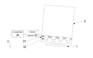
According to an embodiment of the invention, there is provided an exposure device. As illustrated in FIG. 1, the exposure device comprises an exposure lamp 1, a mask plate 2 and a marking equipment 3. The marking equipment 3 includes: a guide rail frame 31, disposed on the mask plate 2; at least one marking vehicle 32, disposed on the guide rail frame 31; and a controller 34, for controlling the guide rail frame 31 to move to a corresponding exposure location on the mask plate 2 earlier than the exposure lamp 1, and for controlling the marking vehicle 32 move to a corresponding marking location, so as to display a corresponding marking identification.
It is to be noted here that, the exposure location and the marking location on the mask plate 2 are fixed, and the exposure lamp 1 is a linear light source, and carries out a horizontal movement relative to the mask plate 1, so as to conduct exposure operations row by row. The exposure location refers to a position in one row on the mask plate 1 where identification patterns need to emerge by exposure, and the marking location refers to a position in correspondence with each identification pattern that needs to emerge by exposure at the exposure location. So, preferably, the number of marking vehicles on the guide rail frame is the number of marking locations contained in one row on the mask plate.
In usual cases, marking locations at individual exposure locations are the same, and after the marking vehicle is moved to a corresponding marking location at a first exposure location, at the next exposure location, it is unnecessary for the controller to control the marking vehicle again for its movement. When marking locations at individual exposure locations on the mask plate are different, after the controller makes the guide rail frame move to the next exposure location on the mask plate earlier than the exposure lamp under its control, it also needs to make the marking vehicle move to a corresponding marking location under its control. For example, the exposure machine is configured to conduct a row-by-row exposure on the mask plate, the direction in which the guide rail moves is perpendicular to a row direction, and the guide rail is configured to be able to make the marking vehicle move in the row direction under its control.
In summary, the exposure lamp 1 moves horizontally to conduct a row-by-row exposure on the mask plate 2, and the controller 34 controls the guide rail frame 31 to move to a corresponding exposure location on the mask plate 2 earlier than the exposure lamp 1. When the exposure lamp moves to a corresponding exposure location where the guide rail frame 1 is located, exposure of an identification pattern can be completed. After exposure of the marking location at the corresponding exposure location is completed, the guide rail frame 31 will move to the next exposure location under the control of the controller 34 earlier, and waits for the exposure lamp 1 to move to the next exposure location, so as to accomplish exposure of an identification pattern at the next exposure location. As such, a one-time exposure is performed on the mask plate 2 with the exposure lamp 1, in which, while exposure of a circuit pattern is finished, exposure is also conducted at every identifying location on the mask plate, so as to accomplish exposure of an identification pattern. Here, in the event that the exposure lamp 1 is engaged in exposure beginning from a boundary of the mask plate 2, the first corresponding exposure location is the exposure location nearest to the boundary of the mask plate 2.
With the exposure device provided by embodiments of the invention, it is possible that while exposure of a circuit pattern is completed, exposure of an identification pattern is also completed. When it is compared to a multiple exposure in prior art, time of the exposure process is greatly saved, and production capacity is enhanced.
For example, as illustrated in FIG. 2, the marking vehicle 32 includes a body module 321 and a display panel module 322 that are assembled together. The display panel module 322 includes an identification display zone 3221 and a transmissive buffer zone 3222 that is located between the body module 321 and the identification display zone 3221. The identification display zone 3221 is used to display a corresponding marking identification as the marking vehicle 32 lies in a corresponding marking location; and the transmissive buffer zone 3222 is use for transmissive display.
Because marking locations on the mask plate 2 are fixed, when the other part of the mask plate 2 is exposed with the exposure lamp 1, the guide rail frame moves to an exposure location earlier, and the marking vehicle moves to a corresponding marking location, for displaying a corresponding marking identification. As illustrated in FIG. 3, at a T1 time, the exposure lamp 1 is going to move to the exposure location. At a T2 time, the exposure lamp 1 goes through an exposure at the identification display zone 3221 of the marking vehicle at a corresponding marking location; and at this time, the exposure lamp 1 is about to enter the transmissive buffer zone 3222 that acts to avoid light of the exposure lamp from being blocked by the body module 321. When light of the exposure lamp will move out of the identification display zone 3221 at the T2 time, the identification display zone 3221 turns into transmissive display, and at the same time, the guide rail frame 31 starts to move to the next marking location, and moving speed of the guide rail frame is greater than moving speed of the exposure lamp. FIG. 3 illustrates relative positions of the exposure lamp 1 and the marking vehicle 32 at a T3 time before the guide rail frame 31 moves to the next exposure location.
For example, the moving speed of the exposure lamp at this time is in the range of 0.2 to 0.3 m/s, and the moving speed of the guide rail frame is in the range of 3.0 to 6.0 m/s.
For example, both the guide rail frame 31 and the N marking vehicles 32 are provided with infrared detectors (not illustrated in the figure), which are used to detect locations of the marking vehicles 32 and the guide rail frame 31 on the mask plate 2.
The infrared detectors can detect distances between a marking vehicle and the guide rail frame and between a marking vehicle and a marking vehicle by infrared detection, so as to detect locations of individual marking vehicles and the guide rail frame 31 on the mask plate. By doing this, the marking vehicles 3 and the guide rail frame 312 can move to corresponding locations on the mask plate 2 under the control of the controller 34.
For example, it is possible that the controller 34 receives location of the guide rail frame 31 on the mask plate 2 detected by the infrared detectors by a wireless transmission technology, and makes the guide rail frame 31 move to a corresponding exposure location on the mask plate 2 under its control. It is also possible that the controller 34 receives locations of the marking vehicles 32 on the mask plate detected by the infrared detectors by a wireless transmission technology, and sends control signals to the marking vehicles by the wireless transmission technology to control the marking vehicles to move to corresponding marking locations, so as to display corresponding marking identifications. As such, interference with the exposure process caused by controlling a marking vehicle through a data wire in prior art is avoided.
For example, as illustrated in FIG. 1, the exposure device further includes a linear motor 33, which is connected to the guide rail frame 31, and acts to drive the guide rail frame 31 to move linearly along a direction perpendicular to the guide rail frame 31 on the mask plate 2. At this time, the controller 34 may take control of movement of the guide rail frame through the linear motor 33.
For example, a marking vehicle 32 is a mask for forming an identification pattern. When a marking operation is conducted, an exposure for forming a marking identification is carried out by enabling light emitted by the exposure lamp 1 to be transmitted through the pattern of the marking vehicle 32. Thus, the marking vehicle may also be called as a marking mask. That is, the same light source can be used as a light source for marking and a light source for exposure of a circuit pattern, and exposure of the circuit pattern and exposure of an identification pattern can be completed synchronously.
For example, in the propagating direction of light emitted by the exposure lamp 1, the exposure lamp 1, the marking vehicle 32 and the mask plate 2 are arranged sequentially in this order.
For example, a portion of the mask plate 2 corresponding to a place in need of marking is pervious to light, and therefore, when a marking operation is conducted, light emitted from the exposure lamp 1 can be transmitted through pattern of the marking vehicle 32 and then transmitted through the mask plate 2, so that an identification pattern emerges through exposure.
For example, after exposure is accomplished, the process for forming marking may be the same as the process for forming the circuit pattern. For example, the identification pattern may be formed by development, etching and other process.
According to an embodiment of the invention, there is further provided an exposure method applied to the above exposure device, comprising the following steps.
101, an exposure lamp moves horizontally to perform an exposure on a mask plate.
102, a controller makes the guide rail frame move to a corresponding exposure location on the mask plate earlier than the exposure lamp under its control, and makes the marking vehicle lie in a corresponding marking location under its control, so as to display a corresponding marking identification.
The step 102 is carried out circularly with the controller while the step 101 is carried out, until exposure locations on the mask plate are all subjected to exposure. In such a way, after the step 101 is accomplished and a one-time exposure is conducted on the mask plate, exposure of a circuit pattern and exposure of an identification pattern are accomplished simultaneously. When it is compared to a multiple exposure in prior art, time of the exposure process is greatly saved, and production capacity is enhanced.
As illustrated in FIG. 2, the marking vehicle 32 includes a body module 321 and a display panel module 322 that are assembled together. The display panel module 322 includes an identification display zone 3221 and a transmissive buffer zone 3222 that is located between the body module 321 and the identification display zone 3221. The identification display zone 3221 is used for display of a corresponding marking identification as the marking vehicle 32 lies in a corresponding marking location; and the transmissive buffer zone 3222 is used for transmissive display. In this case, the step 102 includes the following steps concretely.
1021, after exposure of the identification display zone at a first exposure location on the mask plate with the exposure lamp is finished, the controller takes control of the identification display zone of the marking vehicle for a transmissive display, and meanwhile makes the guide rail frame start to move under its control, so that the guide rail frame moves to a second exposure location on the mask plate earlier than the exposure lamp.
Because marking locations on the mask plate 2 are fixed, when the other part of the mask plate 2 is exposed with the exposure lamp 1, the guide rail frame moves to an exposure location earlier, and the marking vehicle moves to a corresponding marking location, for displaying a corresponding marking identification. As illustrated in FIG. 3, at a T1 time, the exposure lamp 1 is going to move to the exposure location. At a T2 time, the exposure lamp 1 goes through an exposure at the identification display zone 3221 of the marking vehicle at a corresponding marking location; and at this time, the exposure lamp 1 is about to enter the transmissive buffer zone 3222 that acts to avoid light of the exposure lamp from being blocked by the body module 321. When light of the exposure lamp will move out of the identification display zone 3221 at the T2 time, the identification display zone 3221 turns into transmissive display, and at the same time, the guide rail frame 31 starts to move to the next marking location, and moving speed of the guide rail frame is greater than moving speed of the exposure lamp. FIG. 3 illustrates relative positions of the exposure lamp 1 and the marking vehicle 32 at a T3 time before the guide rail frame 31 moves to the next exposure location. For example, at this time, the moving speed of the exposure lamp is in the range of 0.2 to 0.3 m/s, and the moving speed of the guide rail frame is in the range of 3.0 to 6.0 m/s.
Both the guide rail frame and the marking vehicle are provided with infrared detectors, which are used to detect locations of the marking vehicle and the guide rail frame on the mask plate 2. Then, the controller making the marking vehicle lie in a corresponding marking location under its control so as to display a corresponding marking identification as stated in the step 102 and 103 includes that:
the controller receives location of the guide rail frame on the mask plate detected by the infrared detectors by a wireless transmission technology, and makes the guide rail frame move to a corresponding exposure location on the mask plate under its control. Next, the controller receives location of the marking vehicle on the mask plate detected by the infrared detectors by a wireless transmission technology, and sends a control signal to the marking vehicle by the wireless transmission technology to make the marking vehicle move to a corresponding marking location under its control, so as to display a corresponding marking identification. As such, interference with the exposure process caused by controlling a marking vehicle through a data wire in prior art is avoided.
For example, the exposure device further includes a linear motor 33, which is connected to the guide rail frame, and acts to drive the guide rail frame to move linearly along a direction perpendicular to the guide rail frame on the mask plate. Then, the controller taking control of movement of the guide rail frame includes that, the controller takes control of movement of the guide rail frame by controlling the linear motor.
Descriptions made above are merely exemplary embodiments of the invention, but are not used to limit the protection scope of the invention. The protection scope of the invention is determined by attached claims.

Claims (20)

The invention claimed is:
1. An exposure device, comprising: an exposure lamp, a mask plate and a marking equipment, the marking equipment comprising:
a guide rail frame, disposed on the mask plate;
at least one marking vehicle, disposed on the guide rail frame;
a controller, configured to control the guide rail frame move to a corresponding exposure location on the mask plate earlier than the exposure lamp, and to control the marking vehicle lie in a corresponding marking location, for displaying a corresponding marking identification.
2. The device claimed as claim 1, wherein, the marking vehicle is a mask for forming an identification pattern.
3. The device claimed as claim 1, wherein, the marking vehicle includes a body module and a display panel module assembled together;
the display panel module includes: an identification display zone and a transmissive buffer zone that is located between the body module and the identification display zone;
the identification display zone acts to display the corresponding marking identification when the marking vehicle lies in the corresponding marking location;
the transmissive buffer zone acts to conduct a transmissive display.
4. The device claimed as claim 3, wherein, after exposure of a marking location at a first exposure location on the mask plate with the exposure lamp is finished, the controller acts to control the identification display zone of the marking vehicle to perform a transmissive display, and meanwhile to control the guide rail frame start to move, so that the guide rail frame moves to a second exposure location on the mask plate earlier than the exposure lamp.
5. The device claimed as claim 1, wherein, a moving speed of the exposure lamp upon the mask plate being exposed with it is in a range of 0.2 to 0.3 m/s, and a moving speed of the guide rail frame under the control of the controller is in a range of 3.0 to 6.0 m/s.
6. The device claimed as claim 1, wherein, both the guide rail frame and the marking vehicle are provided with infrared detectors, which are used to detect locations of the marking vehicle and the guide rail frame on the mask plate.
7. The device claimed as claim 6, wherein, the controller acts to receive location of the guide rail frame on the mask plate detected by the infrared detectors by a wireless transmission technology, to control the guide rail frame move to the corresponding exposure location on the mask plate, next, to receive location of the marking vehicle on the mask plate detected by the infrared detectors by the wireless transmission technology, and further to send a control signal to the marking vehicle by the wireless transmission technology to control the marking vehicle move to the corresponding marking location, so as to display the corresponding marking identification.
8. The device claimed as claim 7, wherein, the device further comprises a linear motor;
the linear motor is connected to the guide rail frame, and acts to drive the guide rail frame to move linearly along a direction perpendicular to the guide rail frame on the mask plate;
the controller acts to take control of movement of the guide rail frame by controlling the linear motor.
9. The device claimed as claim 1, wherein, the exposure machine is configured to conduct a row-by-row exposure on the mask plate, the direction in which the guide rail moves is perpendicular to a row direction, and the guide rail is configured to be able to control the marking vehicle move in the row direction.
10. The device claimed as claim 1, wherein, in a propagating direction of lights emitted by the exposure lamp, the exposure lamp, the marking vehicle and the mask plate are arranged sequentially in this order.
11. The device claimed as claim 1, wherein, a portion of the mask plate corresponding to a place in need of marking is pervious to light.
12. An exposure method with the exposure device claimed as claim 1, comprising the following steps:
moving the exposure lamp horizontally to conduct an exposure on the mask plate;
making the guide rail frame move to a corresponding exposure location on the mask plate earlier than the exposure lamp under the control of the controller, and making the marking vehicle lie in a corresponding marking location under the control of the controller, so as to display a corresponding marking identification.
13. The method claimed as claim 12, wherein, the marking vehicle includes a body module and a display panel module assembled together; the display panel module includes: an identification display zone and a transmissive buffer zone that is located between the body module and the identification display zone; wherein, the identification display zone acts to display the corresponding marking identification when the marking vehicle lies in the corresponding marking location; the transmissive buffer zone acts to conduct a transmissive display;
making the guide rail frame move to the corresponding exposure location on the mask plate earlier than the exposure lamp under the control of the controller and making the marking vehicle lie in the corresponding marking location under the control of the controller so as to display the corresponding marking identification includes:
after exposure of the identification display zone at a first exposure location on the mask plate with the exposure lamp is finished, making the identification display zone of the marking vehicle perform a transmissive display under the control of the controller, and meanwhile making the guide rail frame start to move under the control of the controller, so that the guide rail frame moves to a second exposure location on the mask plate earlier than the exposure lamp.
14. The method claimed as claim 13, wherein, a moving speed of the exposure lamp upon the mask plate being exposed with it is in a range of 0.2 to 0.3 m/s, and a moving speed of the guide rail frame under the control of the controller is in a range of 3.0 to 6.0 m/s.
15. The method claimed as claim 12, wherein, both the guide rail frame and the marking vehicle are provided with infrared detectors, which are used to detect locations of the marking vehicle and the guide rail frame on the mask plate; and making the marking vehicle lie in a corresponding marking location under the control of the controller so as to display the corresponding marking identification includes:
receiving location of the guide rail frame on the mask plate detected by the infrared detectors through a wireless transmission technology by the controller, making the guide rail frame move to the corresponding exposure location on the mask plate under the control of the controller, afterwards, receiving location of the marking vehicle on the mask plate detected by the infrared detectors through the wireless transmission technology by the controller, and then sending a control signal to the marking vehicle by the wireless transmission technology from the controller to make the marking vehicle lie in the corresponding marking location, so as to display a corresponding marking identification.
16. The method claimed as claim 12, wherein, the device further comprises a linear motor; the linear motor is connected to the guide rail frame, and acts to drive the guide rail frame to move linearly along a direction perpendicular to the guide rail frame on the mask plate; and the control over the movement of the guide rail frame with the controller includes:
taking control of movement of the guide rail frame by means of controlling the linear motor with the controller.
17. The device claimed as claim 2, wherein, the marking vehicle includes a body module and a display panel module assembled together;
the display panel module includes: an identification display zone and a transmissive buffer zone that is located between the body module and the identification display zone;
the identification display zone acts to display the corresponding marking identification when the marking vehicle lies in the corresponding marking location;
the transmissive buffer zone acts to conduct a transmissive display.
18. The device claimed as claim 2, wherein, a moving speed of the exposure lamp upon the mask plate being exposed with it is in a range of 0.2 to 0.3 m/s, and a moving speed of the guide rail frame under the control of the controller is in a range of 3.0 to 6.0 m/s.
19. The device claimed as claim 2, wherein, both the guide rail frame and the marking vehicle are provided with infrared detectors, which are used to detect locations of the marking vehicle and the guide rail frame on the mask plate.
20. The device claimed as claim 2, wherein, the exposure machine is configured to conduct a row-by-row exposure on the mask plate, the direction in which the guide rail moves is perpendicular to a row direction, and the guide rail is configured to be able to control the marking vehicle move in the row direction.
US14/386,245 2013-07-04 2013-12-09 Exposure device and exposure method Expired - Fee Related US9523920B2 (en)

Applications Claiming Priority (4)

Application Number Priority Date Filing Date Title
CN201310278663.5A CN103324037B (en) 2013-07-04 2013-07-04 Exposure device and method
CN201310278663 2013-07-04
CN201310278663.5 2013-07-04
PCT/CN2013/088901 WO2015000263A1 (en) 2013-07-04 2013-12-09 Exposure device and exposure method thereof

Publications (2)

Publication Number Publication Date
US20160238940A1 US20160238940A1 (en) 2016-08-18
US9523920B2 true US9523920B2 (en) 2016-12-20

Family

ID=49192866

Family Applications (1)

Application Number Title Priority Date Filing Date
US14/386,245 Expired - Fee Related US9523920B2 (en) 2013-07-04 2013-12-09 Exposure device and exposure method

Country Status (3)

Country Link
US (1) US9523920B2 (en)
CN (1) CN103324037B (en)
WO (1) WO2015000263A1 (en)

Cited By (1)

* Cited by examiner, † Cited by third party
Publication number Priority date Publication date Assignee Title
US10191214B2 (en) 2017-03-31 2019-01-29 Nokia Of America Corporation Photonic integrated circuit having a relative polarization-rotating splitter/combiner

Families Citing this family (4)

* Cited by examiner, † Cited by third party
Publication number Priority date Publication date Assignee Title
CN103324037B (en) 2013-07-04 2015-01-07 北京京东方光电科技有限公司 Exposure device and method
CN105446083B (en) * 2014-08-28 2018-05-04 上海微电子装备(集团)股份有限公司 It is a kind of that there is the exposure machine of stamp
CN109041441B (en) * 2018-09-14 2024-07-30 东莞市多普光电设备有限公司 Batch management exposure method and exposure equipment for PCB
CN110058496B (en) * 2019-05-16 2021-04-06 昆山国华电子科技有限公司 Circuit board exposure equipment and exposure process

Citations (6)

* Cited by examiner, † Cited by third party
Publication number Priority date Publication date Assignee Title
US6556279B1 (en) * 2001-05-10 2003-04-29 Ultratech Stepper, Inc. Motion compensation system and method for lithography
CN1437713A (en) 2000-06-21 2003-08-20 芳诺·萨尔米 Method for distinctively marking circuit boards
US6634290B1 (en) * 1999-08-10 2003-10-21 Fuji Machine Mfg. Co., Ltd. Mask-printing apparatus and method including inspection of printed material and re-printing step
CN101271825A (en) 2007-03-22 2008-09-24 中芯国际集成电路制造(上海)有限公司 Chip identification production method and light shield
CN103091974A (en) 2013-02-27 2013-05-08 上海华力微电子有限公司 Photolithography mask structure
CN103324037A (en) 2013-07-04 2013-09-25 北京京东方光电科技有限公司 Exposure device and method

Family Cites Families (13)

* Cited by examiner, † Cited by third party
Publication number Priority date Publication date Assignee Title
JPH0682744B2 (en) * 1986-05-30 1994-10-19 キヤノン株式会社 Automatic mask carrier
JP2964522B2 (en) * 1989-03-03 1999-10-18 日本電気株式会社 Semiconductor wafer, method of manufacturing the same, and method of selecting semiconductor chips
US5331371A (en) * 1990-09-26 1994-07-19 Canon Kabushiki Kaisha Alignment and exposure method
JP3477838B2 (en) * 1993-11-11 2003-12-10 株式会社ニコン Scanning exposure apparatus and exposure method
JP2003121982A (en) * 2001-10-11 2003-04-23 Nikon Corp Mask, exposure method, exposure apparatus, and device manufacturing method
JP2006005226A (en) * 2004-06-18 2006-01-05 Nikon Corp Position measuring apparatus, alignment apparatus, exposure apparatus, position measuring method, alignment method, exposure method, and device manufacturing method
KR20080042423A (en) * 2006-11-10 2008-05-15 삼성전자주식회사 Display method including cell ID generation method and the cell ID
US8234603B2 (en) * 2010-07-14 2012-07-31 International Business Machines Corporation Method for fast estimation of lithographic binding patterns in an integrated circuit layout
CN102375331A (en) * 2010-08-12 2012-03-14 富葵精密组件(深圳)有限公司 Circuit board marking system and application method thereof
CN201955619U (en) * 2010-11-29 2011-08-31 上海华虹Nec电子有限公司 Layout structure of photoetching alignment graph in semiconductor manufacture
CN102649376B (en) * 2011-06-21 2014-04-02 北京京东方光电科技有限公司 Titling method and equipment
JP5770041B2 (en) * 2011-07-29 2015-08-26 株式会社ブイ・テクノロジー Photomask and exposure apparatus
CN202735677U (en) * 2012-06-08 2013-02-13 合肥芯硕半导体有限公司 Device for marking inner layer circuit board of laser direct-writing exposure machine

Patent Citations (6)

* Cited by examiner, † Cited by third party
Publication number Priority date Publication date Assignee Title
US6634290B1 (en) * 1999-08-10 2003-10-21 Fuji Machine Mfg. Co., Ltd. Mask-printing apparatus and method including inspection of printed material and re-printing step
CN1437713A (en) 2000-06-21 2003-08-20 芳诺·萨尔米 Method for distinctively marking circuit boards
US6556279B1 (en) * 2001-05-10 2003-04-29 Ultratech Stepper, Inc. Motion compensation system and method for lithography
CN101271825A (en) 2007-03-22 2008-09-24 中芯国际集成电路制造(上海)有限公司 Chip identification production method and light shield
CN103091974A (en) 2013-02-27 2013-05-08 上海华力微电子有限公司 Photolithography mask structure
CN103324037A (en) 2013-07-04 2013-09-25 北京京东方光电科技有限公司 Exposure device and method

Non-Patent Citations (3)

* Cited by examiner, † Cited by third party
Title
First Chinese Office Action Appln. No. 201310278663.5; Dated Aug. 28, 2014.
International Search Report Appln. No. PCT/CN2013/088901; Dated Apr. 16, 2014.
Written Opinion of the International Searching Authority dated Apr. 3, 2014; PCT/CN2013/088901.

Cited By (1)

* Cited by examiner, † Cited by third party
Publication number Priority date Publication date Assignee Title
US10191214B2 (en) 2017-03-31 2019-01-29 Nokia Of America Corporation Photonic integrated circuit having a relative polarization-rotating splitter/combiner

Also Published As

Publication number Publication date
US20160238940A1 (en) 2016-08-18
CN103324037B (en) 2015-01-07
CN103324037A (en) 2013-09-25
WO2015000263A1 (en) 2015-01-08

Similar Documents

Publication Publication Date Title
US9523920B2 (en) Exposure device and exposure method
US10201828B2 (en) Coating system and coating method
US10266297B2 (en) Labeling device
US20160257598A1 (en) Glass sheet acquisition and positioning system and associated method for an inline system for measuring the optical characteristics of a glass sheet
DE102012210891A1 (en) Multi-directional proximity sensor
CN114473631A (en) Gantry synchronous adjustment method for double-drive system
JP2010249744A (en) Image generation device for wiring harness visual inspection, and image generation method for wiring harness visual inspection
JP2013003592A (en) Marking method and equipment thereof
CN106053473A (en) Device and method utilizing mechanical arm to carry out visual positioning detection
CN104062099A (en) Testing device and method for LED light strips with side luminance
CN109104682B (en) Multithreading test method and test system for car audio
CN102385028B (en) Defect point locating method of semiconductor device
US20140339208A1 (en) Laser machining device and adjusting method for same
JP3091424B2 (en) Perforator
US20180352217A1 (en) Apparatus for vehicle-mounted camera calibration and method for vehicle-mounted camera calibration
CN120318163B (en) An intelligent production control system for PCB circuit boards
CN105928952B (en) AOI control system and its control method
CN108376666A (en) A kind of chip wafer positioning system and localization method
KR101259350B1 (en) Electrode pattern inspection device with T-type sensor
DE112016004651T5 (en) ULTRASONIC SPACING SENSOR AND WORKPIECE IDENTIFIER CONTAINING THEM
KR101096065B1 (en) Robot Vision Inspection System and Method Using High Speed Communication Interface
CN205652824U (en) Automatic dress strip device of detector bar
CN114689590B (en) Auxiliary edge inspection device and edge inspection method for polarizing plate automatic optical inspection machine
CN109158325A (en) The device for visual identification of IC punching system kind and recognition methods and application
CN209069242U (en) Screw locking height detecting device and electronic product assembly line

Legal Events

Date Code Title Description
AS Assignment

Owner name: BEIJING BOE OPTOELECTRONICS TECHNOLOGY CO., LTD.,

Free format text: ASSIGNMENT OF ASSIGNORS INTEREST;ASSIGNORS:MA, HAITAO;ZHAO, HAISHENG;REEL/FRAME:033777/0803

Effective date: 20140912

Owner name: BOE TECHNOLOGY GROUP CO., LTD., CHINA

Free format text: ASSIGNMENT OF ASSIGNORS INTEREST;ASSIGNORS:MA, HAITAO;ZHAO, HAISHENG;REEL/FRAME:033777/0803

Effective date: 20140912

STCF Information on status: patent grant

Free format text: PATENTED CASE

MAFP Maintenance fee payment

Free format text: PAYMENT OF MAINTENANCE FEE, 4TH YEAR, LARGE ENTITY (ORIGINAL EVENT CODE: M1551); ENTITY STATUS OF PATENT OWNER: LARGE ENTITY

Year of fee payment: 4

FEPP Fee payment procedure

Free format text: MAINTENANCE FEE REMINDER MAILED (ORIGINAL EVENT CODE: REM.); ENTITY STATUS OF PATENT OWNER: LARGE ENTITY

LAPS Lapse for failure to pay maintenance fees

Free format text: PATENT EXPIRED FOR FAILURE TO PAY MAINTENANCE FEES (ORIGINAL EVENT CODE: EXP.); ENTITY STATUS OF PATENT OWNER: LARGE ENTITY

STCH Information on status: patent discontinuation

Free format text: PATENT EXPIRED DUE TO NONPAYMENT OF MAINTENANCE FEES UNDER 37 CFR 1.362

FP Lapsed due to failure to pay maintenance fee

Effective date: 20241220