US9437111B2 - Boundary detection system - Google Patents
Boundary detection system Download PDFInfo
- Publication number
- US9437111B2 US9437111B2 US14/292,685 US201414292685A US9437111B2 US 9437111 B2 US9437111 B2 US 9437111B2 US 201414292685 A US201414292685 A US 201414292685A US 9437111 B2 US9437111 B2 US 9437111B2
- Authority
- US
- United States
- Prior art keywords
- vehicle
- boundary detection
- threat
- zone
- detection tool
- Prior art date
- Legal status (The legal status is an assumption and is not a legal conclusion. Google has not performed a legal analysis and makes no representation as to the accuracy of the status listed.)
- Active, expires
Links
- 238000001514 detection method Methods 0.000 title claims abstract description 291
- 230000004044 response Effects 0.000 claims abstract description 67
- 238000000034 method Methods 0.000 claims abstract description 32
- 238000004458 analytical method Methods 0.000 claims abstract description 20
- 230000035945 sensitivity Effects 0.000 claims description 35
- 230000001133 acceleration Effects 0.000 claims description 13
- 238000013459 approach Methods 0.000 claims description 12
- 238000012544 monitoring process Methods 0.000 claims description 2
- 230000001154 acute effect Effects 0.000 claims 1
- 238000004891 communication Methods 0.000 abstract description 16
- 230000008569 process Effects 0.000 description 15
- 230000000007 visual effect Effects 0.000 description 6
- 241001465754 Metazoa Species 0.000 description 5
- 230000033001 locomotion Effects 0.000 description 5
- 230000008859 change Effects 0.000 description 4
- 238000012545 processing Methods 0.000 description 4
- 230000003247 decreasing effect Effects 0.000 description 3
- 238000012986 modification Methods 0.000 description 3
- 230000004048 modification Effects 0.000 description 3
- 241000269400 Sirenidae Species 0.000 description 2
- 230000003213 activating effect Effects 0.000 description 2
- 230000009429 distress Effects 0.000 description 2
- 230000006870 function Effects 0.000 description 2
- 230000006855 networking Effects 0.000 description 2
- 230000009118 appropriate response Effects 0.000 description 1
- 230000008901 benefit Effects 0.000 description 1
- 230000005540 biological transmission Effects 0.000 description 1
- 235000012813 breadcrumbs Nutrition 0.000 description 1
- 238000010586 diagram Methods 0.000 description 1
- 238000005516 engineering process Methods 0.000 description 1
- 238000003384 imaging method Methods 0.000 description 1
- 230000007774 longterm Effects 0.000 description 1
- 238000012546 transfer Methods 0.000 description 1
Images


Classifications
-
- B—PERFORMING OPERATIONS; TRANSPORTING
- B60—VEHICLES IN GENERAL
- B60R—VEHICLES, VEHICLE FITTINGS, OR VEHICLE PARTS, NOT OTHERWISE PROVIDED FOR
- B60R21/00—Arrangements or fittings on vehicles for protecting or preventing injuries to occupants or pedestrians in case of accidents or other traffic risks
-
- G—PHYSICS
- G08—SIGNALLING
- G08G—TRAFFIC CONTROL SYSTEMS
- G08G1/00—Traffic control systems for road vehicles
- G08G1/16—Anti-collision systems
- G08G1/165—Anti-collision systems for passive traffic, e.g. including static obstacles, trees
-
- G—PHYSICS
- G08—SIGNALLING
- G08G—TRAFFIC CONTROL SYSTEMS
- G08G1/00—Traffic control systems for road vehicles
- G08G1/16—Anti-collision systems
- G08G1/166—Anti-collision systems for active traffic, e.g. moving vehicles, pedestrians, bikes
-
- B—PERFORMING OPERATIONS; TRANSPORTING
- B60—VEHICLES IN GENERAL
- B60R—VEHICLES, VEHICLE FITTINGS, OR VEHICLE PARTS, NOT OTHERWISE PROVIDED FOR
- B60R21/00—Arrangements or fittings on vehicles for protecting or preventing injuries to occupants or pedestrians in case of accidents or other traffic risks
- B60R21/01—Electrical circuits for triggering passive safety arrangements, e.g. airbags, safety belt tighteners, in case of vehicle accidents or impending vehicle accidents
-
- G—PHYSICS
- G08—SIGNALLING
- G08B—SIGNALLING OR CALLING SYSTEMS; ORDER TELEGRAPHS; ALARM SYSTEMS
- G08B23/00—Alarms responsive to unspecified undesired or abnormal conditions
-
- G—PHYSICS
- G08—SIGNALLING
- G08B—SIGNALLING OR CALLING SYSTEMS; ORDER TELEGRAPHS; ALARM SYSTEMS
- G08B25/00—Alarm systems in which the location of the alarm condition is signalled to a central station, e.g. fire or police telegraphic systems
- G08B25/01—Alarm systems in which the location of the alarm condition is signalled to a central station, e.g. fire or police telegraphic systems characterised by the transmission medium
- G08B25/08—Alarm systems in which the location of the alarm condition is signalled to a central station, e.g. fire or police telegraphic systems characterised by the transmission medium using communication transmission lines
-
- G—PHYSICS
- G08—SIGNALLING
- G08G—TRAFFIC CONTROL SYSTEMS
- G08G1/00—Traffic control systems for road vehicles
-
- B—PERFORMING OPERATIONS; TRANSPORTING
- B60—VEHICLES IN GENERAL
- B60R—VEHICLES, VEHICLE FITTINGS, OR VEHICLE PARTS, NOT OTHERWISE PROVIDED FOR
- B60R21/00—Arrangements or fittings on vehicles for protecting or preventing injuries to occupants or pedestrians in case of accidents or other traffic risks
- B60R2021/003—Arrangements or fittings on vehicles for protecting or preventing injuries to occupants or pedestrians in case of accidents or other traffic risks characterised by occupant or pedestian
Definitions
- This disclosure generally relates to a boundary detection system for tracking the movement of objects outside of a vehicle. More particularly, the boundary detection system is configured to track objects outside of a vehicle in order to warn occupants of the vehicle of potentially threatening situations.
- An occupant of a vehicle may find himself/herself in a situation where it is difficult to accurately track external events that may be occurring outside of the vehicle. In such situations, the occupant may benefit from additional assistance that monitors events and objects outside of the vehicle, and provides a notification to the occupant inside the vehicle.
- Exemplary embodiments provide systems and methods for tracking objects that are outside of a vehicle, analyzing the tracked object in order to determine a potential threat of the tracked object to occupants of the vehicle, and implementing a threat response based on the analysis for protecting the occupants of the vehicle from the tracked object.
- a vehicle boundary detection system includes at least a memory configured to store threat identification information; a sensor unit configured to sense an object outside a vehicle and obtain sensor information based on the sensed object; and a processor in communication with the memory and the sensor unit, the processor being configured to receive the sensor information, and to control a threat response based on at least one of the sensor information or the threat identification information.
- a method for detecting objects within a boundary surrounding a vehicle includes at least storing, within a memory, threat identification information including information for identifying threatening situations; sensing, by a sensor unit, an object located outside a vehicle, and obtaining sensor information based on the sensed object; receiving, by a processor, the sensor information; and controlling, by the processor, a threat response based on at least one of the sensor information or the threat identification information.
- FIG. 1 illustrates a number of boundary detection zones surrounding a vehicle
- FIG. 2 illustrates an exemplary threat detection environment according to some embodiments
- FIG. 3 illustrates an exemplary threat detection environment according to some embodiments
- FIG. 4 illustrates an exemplary vehicle equipped with sensors of the boundary detection system according to some embodiments
- FIG. 5 illustrates an exemplary flow chart describing a process according to some embodiments
- FIG. 6 illustrates an exemplary block diagram including components of the boundary detection system according to some embodiments.
- FIG. 7 illustrates an exemplary table according to some embodiments.
- Components and systems may be included on, and/or within, a vehicle for identifying objects that are detected around the vehicle. By identifying objects that are detected around the vehicle, further analysis may be implemented to determine whether the objects pose a threat to the safety of one or more occupants of the vehicle.
- this disclosure describes a boundary detection system that is included as a feature of a vehicle. One or more components of the boundary detection system may be shared with one or more components of the existing vehicle components.
- the boundary detection system is generally comprised of one or more sensors for detecting objects located within an external vicinity of the vehicle, a memory component for storing information received from the sensors and information that may be referenced when determining a predicted threat level of the detected object in terms of the vehicle occupants, and a processor for determining whether the object may pose a threatening situation for occupants of the vehicle based on the received sensor information and the information stored on the memory.
- the processor may further be configured to control other features and/or components of the vehicle for implementing a threat response based on the determination of whether the object poses a threat.
- the boundary detection system has been described as being comprised of one or more sensors, a memory component and a controller, it is within the scope of this disclosure for the boundary detections system to include a greater, or fewer, number of components.
- the boundary detection system may be utilized, for example, in a consumer passenger vehicle such as a sedan or truck.
- the boundary detection system may also be utilized, for example, on a non-civilian vehicle such as a vehicle used by a law enforcement agency, government agency, an emergency response agency (e.g., fire response agency), or a medical response agency (e.g., hospital or ambulance).
- a non-civilian vehicle such as a vehicle used by a law enforcement agency, government agency, an emergency response agency (e.g., fire response agency), or a medical response agency (e.g., hospital or ambulance).
- a non-civilian vehicle such as a vehicle used by a law enforcement agency, government agency, an emergency response agency (e.g., fire response agency), or a medical response agency (e.g., hospital or ambulance).
- a non-civilian vehicle such as a vehicle used by a law enforcement agency, government agency, an emergency response agency (e.g., fire response agency), or a medical response agency (e
- boundary detection tool running on the boundary detection system.
- the boundary detection tool may be a program, application, and/or some combination of software and hardware that is incorporated on one or more of the components that comprise the boundary detection system.
- the boundary detection tool and the boundary detection system is described in more detail below.
- the vehicle and the features corresponding to the boundary detection tool and boundary detection system described herein are applicable while the vehicle is in a parked (i.e., stationary state), it is also within the scope of this disclosure that the same features may apply while the vehicle is in a moving state.
- the following description is provided based on the boundary detection tool identifying at least three distinct threat level classifications that may be assigned to an object detected outside of the vehicle 100 .
- the three exemplary threat level classifications are no threat level classification, low threat level classification, and high threat level classification.
- an emergency threat level classification may exist that is above the high threat level classification.
- the threat level classifications references are provided for exemplary purposes, as it is within the scope of the boundary detection tool to reference a greater, or fewer, number of threat level classifications.
- the boundary detection tool may identify two distinct threat level classifications: a low threat class, and a high threat class.
- the boundary detection tool may identify a no threat class as the lowest threat level classification, a high threat class as the highest threat level classification, and one or more threat level classifications in-between the no threat class and the high threat class to represent varying levels of threat in-between the no threat class and the high threat class.
- FIG. 1 illustrates a vehicle 100 stationed within an environment that includes a plurality of threat level zones surrounding the vehicle 100 .
- the far zone 101 begins at a distance that is far enough away from an occupied zone 105 (e.g., the occupied zone 105 may represent an area within the vehicle 100 where occupants may be located) of the vehicle 100 such that the boundary detection tool identifies objects within the far zone 101 as being outside a relevant range.
- the far zone 101 may begin at a distance from the occupied zone 105 where the boundary detection tool considers objects to pose little or no threat to occupants within the occupied zone 105 .
- the far zone 101 may being at a distance that corresponds to the maximum sensor range for one or more sensors that comprise the boundary detection system. It follows that an object positioned within the far zone 101 may be considered by the boundary detection tool to be assigned a no threat level classification based on its distance from the occupied zone 105 .
- the next zone in from the far zone 101 and closer to the vehicle 100 is the mid zone 102 .
- An object within the mid zone 102 may be tracked by one or more sensors that comprise the boundary detection system.
- the distances from the occupied zone 105 that comprise the mid zone 102 may correspond to distances at which the boundary detection tool determines is relevant to begin tracking objects that may pose a threat to occupants within the vehicle 100 .
- the outside boundary of the mid zone 102 may correspond to a distance that corresponds to a maximum range of one or more sensors that comprise the boundary detection system.
- an object identified by the boundary detection tool as being a predetermined distance away from the occupied zone 105 to be located within the mid zone 102 may initially be classified within the no threat level classification or the low threat level classification based on its distance from the occupied zone 105 .
- other factors considered by the boundary detection tool may increase an object's assigned threat level classification to a higher threat class (e.g., from the low threat level class to the high threat class, or from the no threat level class to the low threat level class) or decrease an object's assigned threat level class (e.g., from the low threat level class to the no threat level class).
- an object detected within the mid zone 102 may initially be classified by the boundary detection tool as having either no threat or low threat level classification.
- the other factors considered by the boundary detection tool may correspond to sensor information on the object as sensed by one or more sensors included in the boundary detection system (e.g., size of the object, velocity of the object, acceleration of the object, predicted movement/path/trajectory/position/location of the object, or predicted object type of the object).
- size of the object e.g., size of the object, velocity of the object, acceleration of the object, predicted movement/path/trajectory/position/location of the object, or predicted object type of the object.
- the next zone in from the mid zone 102 and closer to the vehicle 100 is the near zone 103 .
- An object within the near zone 103 may be tracked by one or more sensors that comprise the boundary detection system.
- the distances from the occupied zone 105 that comprise the near zone 103 may correspond to distances at which the boundary detection tool determines is relevant to track objects that may pose a threat to occupants within the vehicle 100 .
- an object identified by the boundary detection tool as being a predetermined distance away from the occupied zone 105 to be located within the near zone 103 may initially be classified by the boundary detection tool within the low threat level classification.
- Other factors considered by the boundary detection tool may increase the object's threat level classification to a higher threat class (e.g., from the low threat level to the high threat level class) or decrease the object's threat level to a lower threat class (e.g., from the low threat level class to the no threat level class).
- an object detected within the near zone 103 may initially be classified by the boundary detection tool as having a low threat level classification. A more in-depth description on the additional factors that may change an object's threat level is provided in more detail below.
- the next zone in from the near zone 103 and closer to the vehicle 100 is the critical zone 104 .
- An object within the critical zone 104 may be tracked by one or more sensors that comprise the boundary detection system.
- the distances from the occupied zone 105 that comprise the critical zone 104 may correspond to distances at which the boundary detection tool determines is relevant to track objects that may pose a threat to occupants within the vehicle 100 .
- some embodiments may identify the critical zone 104 to only include the areas immediately adjacent to the driver side and passenger side of the vehicle because this may represent an area where occupants of the vehicle 100 may be most vulnerable. For example, objects moving along the driver side and passenger sides of the vehicle may be more difficult for occupants to detect (e.g., may include “blind spots”), as compared to objects incoming from the front or back sides of the vehicle 100 .
- the occupied zone 104 may include the area to the front and back of the vehicle 100 such that the critical zone 104 includes the area immediately surrounding the vehicle 100 .
- an object identified by the boundary detection tool as having a distance away from the occupied zone 105 to be located within the critical zone 104 may initially be classified by the boundary detection tool within the high threat level classification.
- Other factors considered by the boundary detection tool may increase the object's threat level to a higher threat class (e.g., from the high threat level class to a higher emergency threat level class) or decrease the object's threat level to a lower threat class (e.g., from the high threat level class to the low threat level class).
- an object detected within the critical zone 104 may initially be classified by the boundary detection tool as having a high threat level classification. A more in-depth description on the additional factors that may change an object's threat level is provided in more detail below.
- the next zone in from the critical zone 104 is the occupied zone 105 .
- the occupied zone is an area within the vehicle 100 where the boundary detection tool may understand occupants of the vehicle 100 to be located.
- the occupied zone 105 may correspond to an area within the vehicle 100 where the boundary detection tool has identified one or more occupants of the vehicle 100 to be located based on sensor information received from one or more sensors that comprise the boundary detection system.
- the occupied zone is identified as an area corresponding to occupants within the vehicle 100 , and referenced as a focal point by the boundary detection tool, because the boundary detection tool serves to inform occupants of external influences that may be relevant to the occupants.
- the boundary detection tool may serve to warn occupants of the vehicle 100 concerning objects outside the vehicle 100 that the boundary detection tool has tracked and determined may pose a threat to the occupants.
- an object being tracked from outside the vehicle 100 and then detected within the occupied zone 105 may automatically be classified by the boundary detection tool within the highest threat level classification.
- a more in-depth description on the additional factors that may change an object's threat level is provided in more detail below.
- FIG. 1 is illustrated to identify five distinct zones (far zone, mid zone, near zone, critical zone and occupied zone), the exact number of zones is provided for exemplary purposes only.
- the critical zone 104 may be incorporated into the occupied zone 105 such that the occupied zone may include an area by the passenger or driver side doors, an area immediately encircling the vehicle 100 out to a predetermined distance, or an area within the vehicle 100 where the boundary detection system has determined, or predicted, the occupants are located. Therefore, it is within the scope of this disclosure that the boundary detection tool may identify and reference fewer, or more, zones while still implementing the features described herein. Further, each zone identified by the boundary detection tool may have associated with it one or more threat level classifications as described herein.
- the boundary detection tool may instead identify one or more specified distances from the occupied zone 105 in place of the “zones” referenced above and throughout this disclosure.
- FIG. 2 illustrates an environment where the vehicle 100 is in a parked state off the side of the road.
- the vehicle 100 may be a police vehicle that has parked on the side of the road to conduct police business (e.g., traffic stop, monitoring traffic, etc.).
- police business e.g., traffic stop, monitoring traffic, etc.
- the detection of the vehicle 100 being in the parked state may initialize the boundary detection tool to start its analysis or activate a threat response capability.
- the boundary detection tool may identify the vehicle 100 as being in a parked state based on the vehicle 100 being in the parked gear state, inputs from a motion sensor identifying the vehicle 100 being in a stopped state (even when the vehicle 100 is not in the parked gear state), inputs from an accelerometer sensor identifying the vehicle 100 being in a stopped state (even when the vehicle 100 is not in the parked gear state), or some combination thereof.
- the boundary detection tool may be running in some capacity while the vehicle is moving 100 as long as one or more components (e.g., sensors) of the boundary detection system are operational and detecting information on the surroundings of the vehicle 100 .
- the environment in FIG. 2 is illustrated to include a far zone 101 , a mid zone 102 , a near zone 103 , a critical zone 104 , and an occupied zone 105 that may be identified and referenced by the boundary detection tool.
- the environment in FIG. 2 is also illustrated to include a person 120 (i.e., object) walking away from the occupied zone 105 within the vehicle 100 .
- the person 120 is illustrated as walking away from the occupied zone 105 at a slow and steady pace as indicative from the tracks following the person's walking path.
- the environment illustrated in FIG. 2 also includes a second vehicle 110 driving away from the occupied zone 105 .
- both objects, the person 120 and second vehicle 110 are located within the far zone 101 . It follows that the boundary detection system on the vehicle 100 will detect both the person 120 and the second vehicle 110 within the far zone 101 , and provide such object location information to the boundary detection tool running on the boundary detection system.
- the far zone 101 may be defined to be outside the range of one or more of the sensors that comprise the boundary detection system.
- the person 120 and second vehicle 110 may be considered to be within the no threat class by default as they are at a distance far enough away from the occupied zone 105 that they cannot be accurately detected.
- the boundary detection tool may receive information from the sensors and initially identify the person 120 and second vehicle 110 as being classified within the no threat class based on the person 120 and second vehicle 110 being located at a distance away from the occupied zone 105 to be within the far zone 101 .
- the boundary detection tool may receive additional information on an object as the sensors of the boundary detection system tracks the object.
- the sensors of the boundary detection system may initially detect an object within one or more of the zones surrounding the vehicle 100 (e.g., objects at a distance from the occupied zone 105 to be within the mid zone 102 and further in towards the vehicle 100 ), and proceed to determine the initial position, velocity, speed, and size (length, width, height, radar cross section) of the object within the zones.
- the sensors of the boundary detection system may continue to track the movement of the object (e.g., position, velocity, speed, acceleration) as the object moves within one or more of the zones.
- the boundary detection tool may then generate calculations to predict the trajectory, or predicted further location, of the object and predict a future location or path of the object at a specific future time.
- the boundary detection tool may receive the sensor information from the sensors of the boundary detection system to generate a prediction on the object's type classification.
- the sensor information may provide information on the object's radar cross section, length, width, speed, or shape.
- the boundary detection tool may then cross reference the received sensor information against information that describes the characteristics that may classify an object into a distinct object type classification. Then based on this analysis the boundary detection tool may classify the object into one or more appropriate type classes.
- Exemplary object type classes may include a person class, an animal class (e.g., the animal class may further be classified into a threatening animal class and a non-threatening animal class), a motorized vehicle class (e.g., the motor vehicle class may further be classified into a passenger car class, a government agency vehicle class, and a larger truck class), a non-motorized vehicle class, a stationary object class, or a remote controlled device class.
- the information corresponding to the object type classification may be stored on a memory of the boundary detection system such that the information is accessible to the boundary detection tool.
- the type classes described above are provided for exemplary purposes, as it is within the scope of the boundary detection tool to identify a fewer, or greater, number of type classes when classifying the object type. In this way, the object being sensed may be a person, motorized vehicle, non-motorized vehicle, animal, remote controlled device, or other detectable object.
- the boundary detection tool may recognize an object that is classified into a certain object type class as further corresponding to be classified into a certain threat level class. For example, an object classified into the person class or motor vehicle class may be recognized by the boundary detection tool as being automatically classified into at least a low threat class. Additional factors and information received by the boundary detection tool may then be considered to further maintain the object within the low threat class, increase the object into the high threat class, or decrease the object into the no threat class. Further descriptions on the factors and information relied upon by the boundary detection tool when modifying an object's threat level classification is provided throughout this disclosure.
- FIG. 3 illustrates an environment where an object's threat level classification may be increased or decreased by the boundary detection tool based on the sensor information received from the sensors of the boundary detection system as the object is tracked within the zones surrounding the vehicle 100 .
- FIG. 3 illustrates three objects within the environment surrounding the vehicle 100 .
- the three objects include the second vehicle 110 positioned within the mid zone 102 and moving towards the near zone 103 , the first person 121 walking steadily within the near zone 103 towards the critical zone 104 , and the second person 122 currently within the critical zone 104 and rushing towards the occupied zone 105 .
- the boundary detection tool may initially classify an object within one or more zones based on positional information received from one or more of the sensors that comprised the boundary detection system. For example, the boundary detection tool may receive sensor information detailing a position of the second vehicle 110 and determine that the second vehicle 110 is at a distance from the occupied zone 105 to be within the mid zone 102 . The boundary detection tool may receive sensor information detailing a position of the first person 121 and determine that the first person 121 is at a distance from the occupied zone 105 to be within the near zone 103 . And the boundary detection tool may receive sensor information detailing a position of the second person 122 and determine that the second person 122 is at a distance from the occupied zone 105 to be within the critical zone 104 .
- the boundary detection tool may reference the object's zone position and/or distance from the occupied zone 105 to further assign a threat level classification to the object. For example, the boundary detection tool may further classify the second vehicle 110 into the no threat level class or low threat level class based on the second vehicle 110 being positioned at a distance from the occupied zone 105 to be in the mid zone 102 . The boundary detection tool may further classify the first person 121 into the low threat level class based on the first person 121 being positioned at a distance from the occupied zone 105 to be in the near zone 103 .
- the boundary detection tool may further classify the second person 122 into the high threat level class based on the second person 122 being positioned at a distance from the occupied zone 105 to be in the critical zone 104 .
- the boundary detection tool may not yet assign a threat level classification to the object based on the object's position classification into an identifiable zone.
- the boundary detection tool may reference sensor information received from the one or more of the sensors that comprise the boundary detection system in order to classify each of the objects into an appropriate object type class.
- the boundary detection tool may classify the second vehicle 110 into the motor vehicle type class based on received sensor information.
- the boundary detection tool may classify the first person 121 and second person 122 into the person type class based on sensor information received from the one or more sensors that comprise the boundary detection system.
- the boundary detection tool may then rely on the object's object type classification to further classify the object into a corresponding threat level classification.
- the boundary detection tool may further classify the second vehicle 110 into the low threat level class based on the second vehicle 110 being identified and classified into the motor vehicle class.
- the boundary detection tool may not yet assign a threat level classification to the object based on the object's object type classification.
- the boundary detection tool may continue to receive sensor information from the sensors as they track the objects surrounding the vehicle 100 . Based on the received sensor information, the boundary detection tool may determine a trajectory or predicted path of the object in terms of the occupied zone 105 . For example, in FIG. 3 the boundary detection tool may determine that the second vehicle 110 is moving towards the occupied zone 105 and/or moving from an outer zone (e.g., mid zone 102 ) to a more inner zone (i.e., near zone 103 ) closer to the occupied zone 105 .
- an outer zone e.g., mid zone 102
- a more inner zone i.e., near zone 103
- the boundary detection tool may assign a higher threat level classification to the object, or consider the object's path towards the occupied zone as a factor in maintaining or increasing the object's assigned threat level classification.
- This is exemplified by the second vehicle 110 , the first person 121 , and the second person 122 illustrated in FIG. 3 as advancing towards the occupied zone 105 and/or moving from an outer zone to a more inner zone closer to the vehicle 100 and the occupied zone 105 .
- the advancement of an object towards the occupied zone 105 and/or from an outer zone to a more inner zone may result in the boundary detection tool assigning a higher threat level classification to the objects, or considering a factor for maintaining or increasing each of the object's respective assigned threat level classification.
- the boundary detection tool may determine a rate of approach of the object in terms of the occupied zone 105 based on the sensor information received from the sensors of the boundary detection system.
- the rate of approach may correspond to a velocity, acceleration, deceleration, or other definable movement of the object that can be sensed by one or more sensors of the boundary detection system.
- the rate of approach may be classified, for example, as a fast, medium, steady, or slow rate of approach.
- the boundary detection tool may analyze the sensor information to determine an object's rate of approach towards the occupied zone 105 corresponds to the object accelerating towards the occupied zone and/or accelerating from an outer zone to a more inner zone.
- the boundary detection tool may assign a higher threat level classification to the object, or consider the acceleration towards the occupied zone as a factor in increasing the object's assigned threat level classification.
- the second person 122 is seen to be rapidly accelerating towards the vehicle 100 based on the second person's illustrated footsteps.
- the boundary detection tool may analyze the acceleration of the second person 122 towards the vehicle 100 as a threatening maneuver and assign a higher threat level classification, or further increase the second person's assigned threat level classification.
- the boundary detection tool may assign a lower threat level classification to an object, or decrease an object's assigned threat level classification when the boundary detection tool analyzes received sensor information and determines that the object is moving away from the occupied zone 105 and/or moving from an inner zone to a more outer zone further away from the vehicle 100 and the occupied zone 105 .
- This is exemplified by the person 120 illustrated in FIG. 2 as walking away from the vehicle 100 and the occupied zone 105 . Therefore, an analysis of the received sensor information that finds an object is moving away from the occupied zone 105 may result in the boundary detection tool assigning a lower threat level classification to the object, or considering a factor for maintaining or decreasing the object's assigned threat level classification.
- an analysis of the received sensor information by the boundary detection tool that determines an object is accelerating away from the occupied zone 105 and/or accelerating from an inner zone to a more outer zone further away from the occupied zone may result in the boundary detection tool assigning a lower threat level classification to the object, or considering a factor to decrease the object's assigned threat level classification.
- the boundary detection tool may further receive the sensor information and generate a prediction on the future path of an object (e.g., trajectory) that is being tracked.
- the sensor information collected to determine the object's predicted path may include, but is not limited to, position, past positions, speed, velocity, acceleration, and the like for the object.
- the boundary detection tool may assign a higher threat level classification to the object, or consider a factor to increase the object's assigned threat level classification to a higher threat level.
- the boundary detection tool may assign a lower threat level classification to the object, consider a factor to maintain the object's assigned threat level classification, or consider a factor to decrease the object's assigned threat level classification.
- the boundary detection tool may further receive the sensor information and generate a predicted time to impact/collision for the object being tracked (e.g., second vehicle 110 , first person 121 , or second person 122 ) and the occupied zone 105 and/or vehicle 100 .
- the predicted time to impact information may be calculated by the boundary detection tool based on an analysis of one or more of the following pieces of information: position, past positions, speed, velocity, acceleration, and the like for the object.
- the boundary detection tool may assign a higher threat level classification to the object, or consider a factor to increase the object's assigned threat level classification if the predicted time to impact is less than a predetermined amount of time.
- the boundary detection tool may assign a lower threat level classification to the object, or consider a factor to maintain the object's assigned threat level classification, or consider a factor to decrease the object's assigned threat level classification, if the predicted time to impact is greater than a predetermined amount of time.
- the boundary detection tool may generate a threat level classification to assign to the object.
- the list of factors provided above is for exemplary purposes, as it is within the scope of the disclosure for the boundary detection tool to consider greater, or fewer, factors than those specifically described.
- the boundary detection tool may further adjust the threat level classification based on one or more sensitivity level settings.
- the boundary detection level for example, may be operating in one of two sensitivity level settings: high or low.
- the high sensitivity level may correspond to a heightened sensitivity that applies a higher threat level classification for an object attribute or sensed information when compared to the same object attribute or sensed information under the low sensitivity level.
- FIG. 7 illustrates a table 700 that identifies the difference in threat level classifications assigned to an object based on a sensitivity level the boundary detection tool is operating under. As illustrated by FIG.
- the boundary detection tool may assign a high, or higher, threat level classification to an object when the boundary detection tool is operating a high sensitivity level as opposed to a low sensitivity level. For example, although an object at 5 meters away from the occupied zone 105 may not warrant a high threat classification under a low sensitivity level, the boundary detection tool operating in the high sensitivity level may assign a high threat classification to the same object located 5 meters away from the occupied zone 105 .
- the boundary detection tool may categorize more object attributes as being classified under a high, or higher, threat classification. For example, although under normal conditions (e.g., non-high sensitivity levels or low sensitivity level) the boundary detection tool may not take an object's temperature into consideration, under the higher sensitivity level the boundary detection tool may utilize temperature sensors in order to take the object's temperature into consideration when determining the object's overall threat level classification.
- the table 700 includes exemplary factors (e.g., distance from occupied zone, rate of approach, object type classification) that may be considered by the boundary detection tool when determining the threat level classification of an object, it is within the scope of this disclosure for the boundary detection tool to consider fewer, or greater, number of factors specifically described herein, or not, when determining the threat level classification of an object.
- factors e.g., distance from occupied zone, rate of approach, object type classification
- the sensitivity level of the boundary detection tool may be selected based on an occupant's direct input to control the sensitivity level into the boundary detection tool. In addition or alternatively, the sensitivity level may be changed based on a sensitivity triggering event recognized by the boundary detection tool from an analysis of received sensor information.
- the boundary detection tool may receive sensor information from one or more sensors of the boundary detection system. For example, a recognition by the boundary detection tool that an occupant of the vehicle 100 may be preoccupied (e.g., inputting commands into an on-board computer or other similar computing device that is part of the vehicle 100 or boundary detection system) may cause the boundary detection tool to select the high sensitivity level.
- a recognition by the boundary detection tool that the vehicle 100 is surrounded by a specified number of objects may cause the boundary detection tool to select the high sensitivity level.
- the boundary detection tool may rely on other vehicle 100 devices to recognize scenarios where the high sensitivity level should be selected.
- the boundary detection tool may receive positioning information from a GPS device of the vehicle to recognize the vehicle 100 is in an area known to have a higher crime rate.
- the boundary detection tool may select the high sensitivity status.
- the boundary detection tool may also receive clock information from a time keeping device of the vehicle 100 and recognize it is a time of day (e.g, after/before a certain time) known to have a higher crime rate.
- the boundary detection tool may select the high sensitivity status.
- the boundary detection tool may analyze sensor information and/or vehicle device information to recognize certain scenarios where the low sensitivity level should be selected. For example, recognition by the boundary detection tool that the vehicle 100 is surrounded by a large number of objects may cause the boundary detection tool to select the low sensitivity level in order to limit the number of false alarms due to the known increase in number of detectable objects surrounding the vehicle.
- the boundary detection system may implement a corresponding threat response output.
- the threat response output may be any combination of an audio, visual, or haptic feedback response capability of the boundary the boundary detection system and/or vehicle 100 .
- the corresponding threat response output may be controlled by the boundary detection tool based on the object's threat level classification.
- a list of threat level classifications and their corresponding threat response output information may be stored within a memory of the boundary detection system.
- the boundary detection tool may control the type of threat response output based on the object's threat level classification.
- an object with an assigned threat level classification that at least meets a predetermined threat level may have an audio type of threat response output.
- the boundary detection tool may control a speaker to output a warning message to an occupant of the vehicle 100 warning the occupant about the object being tracked.
- the boundary detection tool may output a different threat response (e.g., audio warning to the occupant, audio warning to the object outside the vehicle 100 , and/or display a warning for the occupant inside the vehicle 100 ).
- the boundary detection tool may have a predetermined set of rules that identify a proper threat response output for an identified threat level classification and object type classification.
- Some of the exemplary threat response outputs that may correspond to a specified threat level classification include, but are not limited to, an audible warning output to the occupants of the vehicle 100 , an audible warning output to the object being tracked by the boundary detection system outside of the vehicle 100 , a haptic warning response for occupants within the vehicle 100 (e.g., a vibrating component within the vehicle cabin seat(s), dashboard, or instrument panel), or a visual notification for an occupant of the vehicle 100 (e.g., a warning message, flag, pop-up icon, or other identifier for informing the occupant about the tracked object outside the vehicle 100 ).
- the boundary detection tool may activate or deactivate one or more threat response medium (e.g., audio, visual, haptic) based on an input received from the user and/or a determination processed by the boundary detection tool based on received sensor inputs.
- the user may desire to maintain a low profile, and therefore disable audio and/or haptic feedback types of threat responses while only allowing visual output types of threat responses to be output by the boundary detection tool.
- the enabling of only the visual mode for outputting a threat response may correspond to a specific mode (e.g., stealth mode) of operation implemented by the threat response tool based on a received user input or analysis of received sensor inputs.
- the user may be preoccupied (e.g., driving) or under a necessity to remain hidden (e.g., need to maintain stealth position in a police stakeout) to be staring at a display screen that outputs visual types of threat responses, and therefore in such embodiments the user may only enable audio and/or haptic types of threat response outputs.
- the disabling of the display screen for outputting a threat response may correspond to a specific mode (e.g., driving mode, or dark mode) of operation by the threat response tool based on a received user input or analysis of received sensor inputs.
- the threat response output may activate or deactivate one or more vehicle actuators in response to the determination of an object's threat level classification.
- vehicle actuators that may be activated or deactivated by the boundary detection tool include vehicle alarm systems, vehicle power door locks, vehicle power windows, vehicle sirens (e.g., police vehicle sirens), vehicle external lights (e.g., police vehicle lights), vehicle audio/radio system, vehicle in-cabin displays, or vehicle ignition system.
- a high level threat level classification may cause the boundary detection tool to initiate a threat response that transmits a distress communication to an off-site central command.
- the central command may, for example, be a police command center, another police vehicle, or another emergency response vehicle.
- the boundary detection tool may request additional support for the occupants in the vehicle.
- the boundary detection tool may initiate a threat response based on a threat response triggering event that may not be directly tied to the object's threat level classification.
- the boundary detection tool may identify a threat response triggering event to be, for example, an object being detected within a predetermined zone, an object being detected within a predetermined distance from the occupied zone 105 and/or vehicle 100 , an object being classified as a predetermined object type, an object predicted to collide with the occupied zone 105 and/or vehicle 100 , an object predicted to collide with the occupied zone 105 and/or 100 within a predetermined time, or an object being classified within a predetermined threat level.
- the boundary detection tool may initiate one or more of the threat responses described above as a corresponding threat response for a recognized threat response triggering event.
- This list of exemplary threat response triggering events is provided for exemplary purposes, and it is within the scope of the present disclosure for the boundary detection tool to recognize fewer, or greater, types of threat response triggering events.
- the parameters of the boundary detection tool described herein may be modified.
- a user may modify the number of identifiable zones, modify the threat level classification corresponding to each identifiable zone, modify the threat level classification corresponding to each object type, modify an increasing factor to an object's assigned threat level classification for a specific sensor input information (e.g., modify the number of threat levels an object will increase when the object is determined to be accelerating towards the vehicle 100 ), modify a decreasing factor to an object's assigned threat level classification for a specific sensor input information (e.g., modify the number of threat levels an object will decrease when the object is determined to be accelerating away the vehicle 100 ), or modify the threat response output that corresponds to a given threat level classification.
- a user may input the commands to modify parameters of the boundary detection tool via an instrument cluster panel that accepts user inputs.
- the boundary detection tool may not accept modifications to its parameters unless the user is able to provide proper authentication information first.
- This list of modifiable parameters of the boundary detection tool is provided for exemplary purposes only, as it is within the scope of this disclosure that the boundary detection tool will allow a user to modify a greater, or fewer, number of parameters than listed.
- the boundary detection tool may control a display unit of the boundary detection system to display any one or more of the information received, generated, or determined by the boundary detection tool as described herein.
- the boundary detection tool may control the display unit to display a representation of an environment surrounding the vehicle 100 similar to the environments illustrated in FIGS. 1, 2, and 3 . Like the environments illustrated in FIGS.
- the boundary detection tool may control the display unit to display the vehicle 100 , one or more zones (e.g., far zone, mid zone, near zone, critical zone, occupied zone), surrounding objects that have been detected and identified by the boundary detection system and boundary detection tool (e.g., second vehicle 110 , first person 121 , second person 122 ), and nearby roads and other road features (e.g., stop signs, traffic signals).
- the boundary detection tool may also control the display unit to display any of the obtained information to overlay the display of the surrounding environment.
- the display of the surrounding environment may include arrows identifying a predicted trajectory of an object, footprints or “breadcrumb” identifiers that identify the previous path of objects as they are tracked within the zones, speed information of an object, velocity information of an object, acceleration information of an object, object type classification of an object, or threat level classification of an object.
- This list of potential information that may be displayed by the boundary detection tool onto a display unit is provided for exemplary purposes, and it is within the scope of the present disclosure to include more, or less, information on such a display.
- the boundary detection tool may generate the environment display based on one or more of the following: sensor information sensed by one or more sensors that comprise the boundary detection system, Global Positioning System (GPS) information obtained by a GPS system that may be part of the boundary detection system, or map layout information stored on a memory of the boundary detection system.
- GPS Global Positioning System
- This list of information that the boundary detection tool may rely upon when generating the display is provided for exemplary purposes, and it is within the scope of the present disclosure for the boundary detection tool to rely on more, or less, information when generating such a display.
- the boundary detection tool may control a data recording device to begin recording sensor information based on a predetermined recording triggering event. Based on the boundary detection tool recognizing a recording triggering event has occurred, the boundary detection tool may control the data recording device to begin recording information.
- the information recorded by the data recording device may be sensor information such as detected position data of an object, speed data of an object, velocity data of an object, acceleration data of an object, a video camera recording of an object, or a snapshot digital image of an object.
- the information recorded by the data recording device may also be information generated by the boundary detection tool based on an analysis of received sensor information such as an object's object type classification or threat level classification. This list of information that may be recorded by the data recording device is provided for exemplary purposes, and it is within the scope of the present disclosure for the data recording device to record fewer, or greater, types of information.
- one or more types of information may be recorded for a predetermined amount of time before or after the recording triggering event is recognized.
- the boundary detection tool may control the data recording device to begin recording one or more types of information for a set amount of time (e.g., record information for 1 minute) before and/or after the recording trigger event is recognized.
- one or more types of information may be recorded by the data recording device throughout the duration of the predetermined recording triggering event being active.
- the boundary detection tool may identify a recording triggering event to be, for example, an object being detected within a predetermined zone, an object being detected within a predetermined distance from the occupied zone 105 and/or vehicle 100 , an object being classified as a predetermined object type, an object predicted to collide with the occupied zone 105 and/or vehicle 100 , an object predicted to collide with the occupied zone 105 and/or 100 within a predetermined time, or an object being classified within a predetermined threat level.
- This list of exemplary recording triggering events is provided for exemplary purposes, and it is within the scope of the present disclosure for the boundary detection tool to recognize fewer, or greater, types of recording triggering events.
- a user may access the information by retrieving it (e.g., removing a removable memory component of the data recording device, or downloading the information via a wired or wireless data transfer interface), copying it, viewing it, or clearing the information from the data recording device logs.
- the boundary detection tool may require the user to input the proper credentials in order to access the information stored on the data recording device.
- the boundary detection tool may determine when to activate the threat response outputs based on the recognition of a response output triggering event.
- the sensors of the boundary detection system may be tracking and obtaining sensor information on an object surrounding the vehicle 100 , and the boundary detection tool may be implementing the features described throughout this description, but the corresponding threat response output may be withheld until the boundary detection tool recognizes the appropriate response output triggering event.
- a threat response output triggering event may require the boundary detection tool to first make a determination that the vehicle 100 is in a parked state before activating the threat response outputs.
- the boundary detection tool may determine the vehicle 100 is in the parked state based on sensor information received from one or more sensors of the boundary detection tool that identify the vehicle 100 as not moving, or at least moving below a predetermined minimal speed.
- the boundary detection tool may also determine the vehicle 100 is in the parked state based on information received from the vehicle 100 identifying that the vehicle 100 is in the parked gear setting.
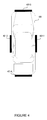
- FIG. 4 illustrates the vehicle 100 and a set of sensors that may comprise the boundary detection system described herein.
- the passenger side sensor unit 401 - 1 may be comprised of one or more sensors that are configured to sense objects on the passenger side of the vehicle 100 .
- the driver side sensor unit 401 - 2 may be comprised of one or more sensors that are configured to sense objects on the driver side of the vehicle 100 .
- the front side sensor unit 401 - 3 may be comprised of one or more sensors that are configured to sense objects on the front side of the vehicle 100 .
- the back side sensor unit 401 - 4 may be comprised of one or more sensors that are configured to sense objects on the back side of the vehicle 100 .
- the sensors that comprise the sensor units may include one or more of the following: a radar sensor, an ultrasonic sensor, a camera, a video camera, an infrared sensor, a lidar sensor, or other similar types of sensors for detecting and tracking an object that may surround a vehicle.
- the boundary detection system may detect and track an object outside of the vehicle 100 .
- FIG. 4 illustrates 4 separate sensor units ( 401 - 1 , 401 - 2 , 401 - 3 , and 401 - 4 ), it is within the scope of this disclosure that the boundary detection system includes a fewer, or greater, number of sensor units.
- the sensor units may only be found on the passenger side and driver side as threatening objects may be determined to more predominately approach a vehicle from these two sides.
- one or more of the sensor units may be utilized to sense objects that are above or below the vehicle 100 .
- FIG. 5 illustrates a flow chart 500 describing a process for achieving one or more of the features of the boundary detection tool described throughout this disclosure.
- the boundary detection tool may make a determination as to whether a proper response output triggering event (e.g., determining whether the vehicle is parked) is recognized from sensor information received by the boundary detection tool. If the boundary detection tool determines that the threat response outputs should not be activated, the process returns to the start and back to 501 until the proper conditions for activating the threat response outputs are recognized by the boundary detection tool.
- the boundary detection tool determines that the proper conditions are met at 501 , then the process proceeds to 502 where the boundary detection tool receives sensor information from one or more sensors that comprise the boundary detection system.
- the sensor information may correspond to the detection and tracking of an object outside of a vehicle. Descriptions of the boundary detection system receiving sensor information from one or more sensors of the boundary detection system are provided throughout this disclosure. The sensors that may comprise the boundary detection system are described throughout this disclosure. For example, exemplary sensors have been described with reference to FIG. 4 above, and described in additional detail with reference to FIG. 6 below.
- the boundary detection tool may analyze the received sensor information and identify an object that has been detected by the sensors. For example, the boundary detection tool may analyze the received sensor inputs and classify the object into one or more of object type classifications according to any one or more of the methods described above. Also at 503 , the boundary detection tool may analyze additional sensor information to determine a distance of the object from an occupied zone of the vehicle, predict a path of the object, determine a rate of approach of the object in terms of the occupied zone and/or vehicle, or predict a time to collision of the object in terms of the occupied zone and/or vehicle.
- the boundary detection tool may determine a threat level classification for the object based on the object type classification from 503 and/or the analysis of the additional sensor information received from the one or more sensors of the boundary detection system.
- the boundary detection tool may determine the threat level classification to assign to the object according to any one or more of the methods described above.
- the boundary detection tool may further increase, maintain, or decrease a previously assigned threat level classification corresponding to the object based on the object type classification and/or the analysis of the additional sensor information according to one or more of the methods described above.
- the boundary detection tool may implement a proper threat response output based on the threat level classification assigned to the object at 504 .
- the boundary detection tool may implement the proper threat response output according to any one or more of the methods described above.
- the process described by flow chart 500 is provided for exemplary purposes only. It is within the scope of the boundary detection tool described in this disclosure to achieve any one or more of the features, processes, and methods described herein by implementing a process that may include fewer, or greater, number of processes than described by flow chart 500 .
- the processes described with reference to 501 may be optional such that they may not be implemented by the boundary detection tool.
- the boundary detection tool may not be limited to the order of processes described in flow chart 500 in order to achieve the same, or similar, results.
- FIG. 6 illustrates an exemplary boundary detection system 600 that may be used for one or more of the components of the boundary detection system described herein, or in any other system configured to carry out the methods and features discussed above.
- the boundary detection system 600 may include a set of instructions that can be executed to cause the boundary detection system 600 to perform any one or more of the methods, processes, or features described herein.
- the processing unit 610 may include a processor 611 and a memory 612 .
- the boundary detection tool described throughout this disclosure may be a program that is comprised of a set of instructions stored on the memory 612 that are executed by the processor 611 to cause the boundary detection tool and boundary detection system 600 to perform any one or more of the methods, processes, or features described herein.
- the boundary detection system 600 may further be comprised of system input components that include, but are not limited to, radar sensor(s) 620 , infrared sensor(s) 621 , ultrasonic sensor(s) 622 , camera 623 (e.g., capable of capturing digital still images, streaming video, and digital video), instrument cluster inputs 624 , and vehicle sensor(s) 625 .
- the boundary detection system 600 may receive information inputs from one or more of these system input components. It is further within the scope of this disclosure that the boundary detection system 600 receives input information from another component not expressly illustrated in FIG. 6 such as a lidar sensor or other imaging technologies.
- the input components are in communication with the processing unit 610 via the communications bus 605 .
- the boundary detection system 600 may include an additional gateway module (not expressly illustrated) in-between the system input components and the processing unit 610 to better allow for communication between the two. Inputs into the boundary detection tool and the boundary detection system described throughout this disclosure may be inputted via one or more of the system input components described herein.
- the boundary detection system 600 may further include system output components such as instrument cluster outputs 630 , actuators 631 , center display 632 , and data recording device 633 .
- the system output components are in communication with the processing unit 610 via the communications bus 605 .
- Information output by the boundary detection tool and the boundary detection system described throughout this disclosure may be implemented according to one or more of the system input components described here.
- the threat response outputs may be implemented according to one or more of the system output components described herein.
- the boundary detection system 600 may also include speakers for outputting audible alerts. The speakers may be part of the instrument cluster or part of other vehicle subsystems such as the infotainment system.
- the boundary detection system 600 is illustrated in FIG. 6 to further include a communications unit 634 .
- the communications unit 634 may be comprised of a network interface (either wired or wireless) for communication with an external network 640 .
- the external network 640 may be a collection of one or more networks, including standards-based networks (e.g., 2G, 3G, 4G, Universal Mobile Telecommunications System (UMTS), GSM (R) Association, Long Term Evolution (LTE) (TM), or more), WiMAX, Bluetooth, near field communication (NFC), WiFi (including 802.11 a/b/g/n/ac or others), WiGig, Global Positioning System (GPS) networks, and others available at the time of the filing of this application or that may be developed in the future.
- the network(s) may be a public network, such as the Internet, a private network, such as an intranet, or combinations thereof, and may utilize a variety of networking protocols now available or later developed including, but not limited to TCP/IP based networking protocols
- the program that embodies the boundary detection tool may be downloaded and stored on the memory 612 via transmission through the network 640 from an off-site server. Further, in some embodiments the boundary detection tool running on the boundary detection system 600 may communicate with a central command server via the network 640 . For example, the boundary detection tool may communicate sensor information received from the sensors of the boundary detection system 600 to the central command server by controlling the communications unit 634 to transmit the information to the central command server via the network 640 . The boundary detection tool may also communicate any one or more of the generated data (e.g., object type classification or threat level classification) to the central command server.
- the generated data e.g., object type classification or threat level classification
- the boundary detection tool may also transmit data recorded into the data recording device 633 , and as described throughout this disclosure, to the central command server by controlling the recorded data to be transmitted through the communications unit 634 to the central command server via the network 640 .
- the central command server may transmit response information back to the boundary detection tool via the network 640 , where the response information is received by the communications unit 634 .
Landscapes
- Physics & Mathematics (AREA)
- General Physics & Mathematics (AREA)
- Business, Economics & Management (AREA)
- Emergency Management (AREA)
- Engineering & Computer Science (AREA)
- Mechanical Engineering (AREA)
- Traffic Control Systems (AREA)
- Alarm Systems (AREA)
- Radar Systems Or Details Thereof (AREA)
Priority Applications (7)
| Application Number | Priority Date | Filing Date | Title |
|---|---|---|---|
| US14/292,685 US9437111B2 (en) | 2014-05-30 | 2014-05-30 | Boundary detection system |
| DE102015108366.3A DE102015108366B4 (de) | 2014-05-30 | 2015-05-27 | Bereichsgrenzen-erkennungssystem |
| MX2015006744A MX348720B (es) | 2014-05-30 | 2015-05-28 | Sistema de deteccion en la periferia. |
| CN201510290215.6A CN105292036B (zh) | 2014-05-30 | 2015-05-29 | 边界检测系统 |
| RU2015120679A RU2678909C2 (ru) | 2014-05-30 | 2015-06-01 | Система для отслеживания объектов вокруг транспортного средства |
| US15/255,896 US9672744B2 (en) | 2014-05-30 | 2016-09-02 | Boundary detection system |
| US15/614,370 US10089879B2 (en) | 2014-05-30 | 2017-06-05 | Boundary detection system |
Applications Claiming Priority (1)
| Application Number | Priority Date | Filing Date | Title |
|---|---|---|---|
| US14/292,685 US9437111B2 (en) | 2014-05-30 | 2014-05-30 | Boundary detection system |
Related Child Applications (1)
| Application Number | Title | Priority Date | Filing Date |
|---|---|---|---|
| US15/255,896 Continuation US9672744B2 (en) | 2014-05-30 | 2016-09-02 | Boundary detection system |
Publications (2)
| Publication Number | Publication Date |
|---|---|
| US20150348417A1 US20150348417A1 (en) | 2015-12-03 |
| US9437111B2 true US9437111B2 (en) | 2016-09-06 |
Family
ID=54481644
Family Applications (3)
| Application Number | Title | Priority Date | Filing Date |
|---|---|---|---|
| US14/292,685 Active 2034-07-16 US9437111B2 (en) | 2014-05-30 | 2014-05-30 | Boundary detection system |
| US15/255,896 Active US9672744B2 (en) | 2014-05-30 | 2016-09-02 | Boundary detection system |
| US15/614,370 Active US10089879B2 (en) | 2014-05-30 | 2017-06-05 | Boundary detection system |
Family Applications After (2)
| Application Number | Title | Priority Date | Filing Date |
|---|---|---|---|
| US15/255,896 Active US9672744B2 (en) | 2014-05-30 | 2016-09-02 | Boundary detection system |
| US15/614,370 Active US10089879B2 (en) | 2014-05-30 | 2017-06-05 | Boundary detection system |
Country Status (5)
| Country | Link |
|---|---|
| US (3) | US9437111B2 (de) |
| CN (1) | CN105292036B (de) |
| DE (1) | DE102015108366B4 (de) |
| MX (1) | MX348720B (de) |
| RU (1) | RU2678909C2 (de) |
Cited By (16)
| Publication number | Priority date | Publication date | Assignee | Title |
|---|---|---|---|---|
| US20150307093A1 (en) * | 2014-04-24 | 2015-10-29 | Honda Motor Co., Ltd. | Collision avoidance assist apparatus, collision avoidance assist method, and program |
| US20170278399A1 (en) * | 2014-05-30 | 2017-09-28 | Ford Global Technologies, Llc | Boundary detection system |
| US10000103B2 (en) * | 2015-05-28 | 2018-06-19 | Ford Global Technologies, Llc | Method of controlling a vehicle active suspension system |
| US10031522B2 (en) * | 2015-05-27 | 2018-07-24 | Dov Moran | Alerting predicted accidents between driverless cars |
| EP3432283A1 (de) * | 2017-07-18 | 2019-01-23 | Aptiv Technologies Limited | System für sicheres verlassen zum sicherheitsschutz eines insassen, der ein automones fahrzeug verlässt |
| US10322696B2 (en) | 2017-01-18 | 2019-06-18 | Gm Global Technology Operations Llc. | Vehicle environment imaging systems and methods |
| US20190308587A1 (en) * | 2018-04-04 | 2019-10-10 | Ford Global Technologies, Llc | Vehicle lighting system featuring object identification and threat level assessment |
| US10497232B1 (en) | 2019-03-01 | 2019-12-03 | Motorola Solutions, Inc. | System and method for dynamic vehicular threat detection perimeter modification for an exited vehicular occupant |
| US10780822B1 (en) | 2019-05-20 | 2020-09-22 | Ford Global Technologies, Llc | Vehicle exclusion zone monitoring assembly and method |
| US10902722B2 (en) | 2017-05-11 | 2021-01-26 | Motorola Solutions, Inc. | Method for providing incident specific information at a vehicle computer |
| US11002827B2 (en) * | 2019-05-21 | 2021-05-11 | Motorola Solutions, Inc. | System and method for collaborating between vehicular 360 degree threat detection appliances |
| US11226624B2 (en) | 2019-04-11 | 2022-01-18 | Motorola Solutions, Inc. | System and method for enabling a 360-degree threat detection sensor system to monitor an area of interest surrounding a vehicle |
| US11335194B1 (en) | 2021-03-26 | 2022-05-17 | Toyota Research Institute, Inc. | Inverse parking distance control system |
| US11414083B2 (en) * | 2017-12-21 | 2022-08-16 | Continental Teves Ag & Co. Ohg | Method and system for avoiding lateral collisions |
| US20230054457A1 (en) * | 2021-08-05 | 2023-02-23 | Ford Global Technologies, Llc | System and method for vehicle security monitoring |
| US11950567B2 (en) | 2021-03-04 | 2024-04-09 | Sky View Environmental Service Llc | Condor monitoring systems and related methods |
Families Citing this family (91)
| Publication number | Priority date | Publication date | Assignee | Title |
|---|---|---|---|---|
| US9411327B2 (en) | 2012-08-27 | 2016-08-09 | Johnson Controls Technology Company | Systems and methods for classifying data in building automation systems |
| US9522676B2 (en) * | 2014-04-30 | 2016-12-20 | Denso International America, Inc. | Situation awareness assistant for vehicle control |
| US10534326B2 (en) | 2015-10-21 | 2020-01-14 | Johnson Controls Technology Company | Building automation system with integrated building information model |
| JP6639194B2 (ja) * | 2015-11-06 | 2020-02-05 | トヨタ自動車株式会社 | 情報表示装置 |
| US9758092B2 (en) * | 2015-12-15 | 2017-09-12 | Sony Corporation | System and method for generating a parking alert |
| US9460616B1 (en) | 2015-12-16 | 2016-10-04 | International Business Machines Corporation | Management of mobile objects and service platform for mobile objects |
| US11268732B2 (en) | 2016-01-22 | 2022-03-08 | Johnson Controls Technology Company | Building energy management system with energy analytics |
| US11947785B2 (en) | 2016-01-22 | 2024-04-02 | Johnson Controls Technology Company | Building system with a building graph |
| DE102016101901A1 (de) | 2016-02-03 | 2017-08-03 | Deutsches Zentrum für Luft- und Raumfahrt e.V. | Fahrerassistenzsystem |
| JP2017136968A (ja) * | 2016-02-04 | 2017-08-10 | 日立オートモティブシステムズ株式会社 | 車両制御装置 |
| US11768004B2 (en) | 2016-03-31 | 2023-09-26 | Johnson Controls Tyco IP Holdings LLP | HVAC device registration in a distributed building management system |
| US10505756B2 (en) | 2017-02-10 | 2019-12-10 | Johnson Controls Technology Company | Building management system with space graphs |
| US10417451B2 (en) | 2017-09-27 | 2019-09-17 | Johnson Controls Technology Company | Building system with smart entity personal identifying information (PII) masking |
| US10901373B2 (en) | 2017-06-15 | 2021-01-26 | Johnson Controls Technology Company | Building management system with artificial intelligence for unified agent based control of building subsystems |
| US11774920B2 (en) | 2016-05-04 | 2023-10-03 | Johnson Controls Technology Company | Building system with user presentation composition based on building context |
| US10139827B2 (en) * | 2016-06-28 | 2018-11-27 | Ford Global Technologies, Llc | Detecting physical threats approaching a vehicle |
| US9984567B2 (en) * | 2016-09-09 | 2018-05-29 | Ford Global Technologies, Llc | Detection of oncoming vehicles with IR light |
| US20180081357A1 (en) * | 2016-09-16 | 2018-03-22 | Ford Global Technologies, Llc | Geocoded information aided vehicle warning |
| CN106448047A (zh) * | 2016-10-27 | 2017-02-22 | 深圳市元征软件开发有限公司 | 车辆安全预警方法及装置 |
| US10684033B2 (en) | 2017-01-06 | 2020-06-16 | Johnson Controls Technology Company | HVAC system with automated device pairing |
| US11900287B2 (en) | 2017-05-25 | 2024-02-13 | Johnson Controls Tyco IP Holdings LLP | Model predictive maintenance system with budgetary constraints |
| US11360447B2 (en) | 2017-02-10 | 2022-06-14 | Johnson Controls Technology Company | Building smart entity system with agent based communication and control |
| US10854194B2 (en) | 2017-02-10 | 2020-12-01 | Johnson Controls Technology Company | Building system with digital twin based data ingestion and processing |
| US10515098B2 (en) | 2017-02-10 | 2019-12-24 | Johnson Controls Technology Company | Building management smart entity creation and maintenance using time series data |
| US10095756B2 (en) | 2017-02-10 | 2018-10-09 | Johnson Controls Technology Company | Building management system with declarative views of timeseries data |
| US20190361412A1 (en) | 2017-02-10 | 2019-11-28 | Johnson Controls Technology Company | Building smart entity system with agent based data ingestion and entity creation using time series data |
| US11280509B2 (en) | 2017-07-17 | 2022-03-22 | Johnson Controls Technology Company | Systems and methods for agent based building simulation for optimal control |
| US11764991B2 (en) | 2017-02-10 | 2023-09-19 | Johnson Controls Technology Company | Building management system with identity management |
| US11307538B2 (en) | 2017-02-10 | 2022-04-19 | Johnson Controls Technology Company | Web services platform with cloud-eased feedback control |
| US10807567B2 (en) * | 2017-02-21 | 2020-10-20 | Ford Global Technologies, Llc | Vehicle proximity tracking |
| US10911725B2 (en) * | 2017-03-09 | 2021-02-02 | Digital Ally, Inc. | System for automatically triggering a recording |
| WO2018175912A1 (en) | 2017-03-24 | 2018-09-27 | Johnson Controls Technology Company | Building management system with dynamic channel communication |
| US10421436B2 (en) * | 2017-03-24 | 2019-09-24 | Toyota Motor Engineering & Manufacturing North America, Inc. | Systems and methods for surveillance of a vehicle using camera images |
| US11327737B2 (en) | 2017-04-21 | 2022-05-10 | Johnson Controls Tyco IP Holdings LLP | Building management system with cloud management of gateway configurations |
| US10788229B2 (en) | 2017-05-10 | 2020-09-29 | Johnson Controls Technology Company | Building management system with a distributed blockchain database |
| US10256674B2 (en) * | 2017-05-23 | 2019-04-09 | Witricity Corporation | Wireless charging transmitter with foreign object and living object detection systems |
| US11022947B2 (en) | 2017-06-07 | 2021-06-01 | Johnson Controls Technology Company | Building energy optimization system with economic load demand response (ELDR) optimization and ELDR user interfaces |
| DE112017007636T5 (de) * | 2017-06-12 | 2020-09-24 | Continental Automotive Gmbh | Heckseitiges Pre-Crash-Sicherheitssystem |
| EP3655825B1 (de) | 2017-07-21 | 2023-11-22 | Johnson Controls Tyco IP Holdings LLP | Gebäudeverwaltungssystem mit dynamischen regeln mit unterregelwiederverwendung und gleichungsgesteuerter intelligenter diagnose |
| US20190033811A1 (en) | 2017-07-27 | 2019-01-31 | Johnson Controls Technology Company | Building management system with on-demand meter roll-ups |
| US20190071043A1 (en) * | 2017-09-06 | 2019-03-07 | Panasonic Automotive Systems Company of Americ Division of Panasonic Corporation of North America | Advanced collision detection and enhanced automotive crash notification |
| JP6859907B2 (ja) | 2017-09-08 | 2021-04-14 | トヨタ自動車株式会社 | 車両制御装置 |
| US11314726B2 (en) | 2017-09-27 | 2022-04-26 | Johnson Controls Tyco IP Holdings LLP | Web services for smart entity management for sensor systems |
| US20190138512A1 (en) | 2017-09-27 | 2019-05-09 | Johnson Controls Technology Company | Building risk analysis system with dynamic and base line risk |
| US10962945B2 (en) | 2017-09-27 | 2021-03-30 | Johnson Controls Technology Company | Building management system with integration of data into smart entities |
| US11314788B2 (en) | 2017-09-27 | 2022-04-26 | Johnson Controls Tyco IP Holdings LLP | Smart entity management for building management systems |
| US10565844B2 (en) | 2017-09-27 | 2020-02-18 | Johnson Controls Technology Company | Building risk analysis system with global risk dashboard |
| US10809682B2 (en) | 2017-11-15 | 2020-10-20 | Johnson Controls Technology Company | Building management system with optimized processing of building system data |
| US11281169B2 (en) | 2017-11-15 | 2022-03-22 | Johnson Controls Tyco IP Holdings LLP | Building management system with point virtualization for online meters |
| US11127235B2 (en) | 2017-11-22 | 2021-09-21 | Johnson Controls Tyco IP Holdings LLP | Building campus with integrated smart environment |
| US10501085B2 (en) | 2017-12-07 | 2019-12-10 | Waymo Llc | Early object detection for unprotected turns |
| US10752218B2 (en) * | 2018-02-22 | 2020-08-25 | Ford Global Technologies, Llc | Camera with cleaning system |
| US11954713B2 (en) | 2018-03-13 | 2024-04-09 | Johnson Controls Tyco IP Holdings LLP | Variable refrigerant flow system with electricity consumption apportionment |
| US20190315345A1 (en) * | 2018-04-16 | 2019-10-17 | David E. Newman | Blind spot potential-hazard avoidance system |
| JP7111517B2 (ja) * | 2018-06-14 | 2022-08-02 | シャープ株式会社 | 走行装置、走行装置の走行制御方法、走行装置の走行制御プログラムおよび記録媒体 |
| CN109255944B (zh) * | 2018-10-08 | 2021-08-17 | 长安大学 | 交通事故应急救援车辆的配置与派遣方法 |
| US11016648B2 (en) | 2018-10-30 | 2021-05-25 | Johnson Controls Technology Company | Systems and methods for entity visualization and management with an entity node editor |
| US11927925B2 (en) | 2018-11-19 | 2024-03-12 | Johnson Controls Tyco IP Holdings LLP | Building system with a time correlated reliability data stream |
| US10810866B2 (en) * | 2018-12-19 | 2020-10-20 | Federal Signal Corporation | Perimeter breach warning system |
| US10816635B1 (en) | 2018-12-20 | 2020-10-27 | Autonomous Roadway Intelligence, Llc | Autonomous vehicle localization system |
| US11099266B2 (en) * | 2019-01-11 | 2021-08-24 | International Business Machines Corporation | Trajectory based threat alerting with friendly device augmentation |
| US11436567B2 (en) | 2019-01-18 | 2022-09-06 | Johnson Controls Tyco IP Holdings LLP | Conference room management system |
| US10788798B2 (en) | 2019-01-28 | 2020-09-29 | Johnson Controls Technology Company | Building management system with hybrid edge-cloud processing |
| US10713950B1 (en) | 2019-06-13 | 2020-07-14 | Autonomous Roadway Intelligence, Llc | Rapid wireless communication for vehicle collision mitigation |
| US11442171B2 (en) * | 2019-07-26 | 2022-09-13 | 6 Watch, Inc. | Threat detection and notification system for public safety vehicles |
| US11106912B1 (en) | 2019-08-05 | 2021-08-31 | Genetec Inc. | Method and system for video content analysis |
| DE102019213155A1 (de) * | 2019-08-30 | 2021-03-04 | Robert Bosch Gmbh | Verfahren und Vorrichtung zum Betreiben eines Fahrzeugs |
| JP7247849B2 (ja) * | 2019-10-11 | 2023-03-29 | トヨタ自動車株式会社 | 駐車支援装置 |
| US11592575B2 (en) * | 2019-12-20 | 2023-02-28 | Waymo Llc | Sensor steering for multi-directional long-range perception |
| US20210200164A1 (en) | 2019-12-31 | 2021-07-01 | Johnson Controls Technology Company | Building data platform with edge based event enrichment |
| US11894944B2 (en) | 2019-12-31 | 2024-02-06 | Johnson Controls Tyco IP Holdings LLP | Building data platform with an enrichment loop |
| US11351998B2 (en) | 2020-03-18 | 2022-06-07 | Denso Corporation | Systems and methods for adapting activation of alerts according to curvature of a target path |
| US11537386B2 (en) | 2020-04-06 | 2022-12-27 | Johnson Controls Tyco IP Holdings LLP | Building system with dynamic configuration of network resources for 5G networks |
| JP7327257B2 (ja) * | 2020-04-13 | 2023-08-16 | トヨタ自動車株式会社 | 車載センサシステム |
| US11874809B2 (en) | 2020-06-08 | 2024-01-16 | Johnson Controls Tyco IP Holdings LLP | Building system with naming schema encoding entity type and entity relationships |
| US11954154B2 (en) | 2020-09-30 | 2024-04-09 | Johnson Controls Tyco IP Holdings LLP | Building management system with semantic model integration |
| US11397773B2 (en) | 2020-09-30 | 2022-07-26 | Johnson Controls Tyco IP Holdings LLP | Building management system with semantic model integration |
| US20220137575A1 (en) | 2020-10-30 | 2022-05-05 | Johnson Controls Technology Company | Building management system with dynamic building model enhanced by digital twins |
| CN114913691A (zh) * | 2021-02-08 | 2022-08-16 | 上海擎感智能科技有限公司 | 车辆的控制方法、系统、车载终端、汽车及存储介质 |
| CN117280291A (zh) | 2021-03-17 | 2023-12-22 | 江森自控泰科知识产权控股有限责任合伙公司 | 用于确定设备能量浪费的系统和方法 |
| US11769066B2 (en) | 2021-11-17 | 2023-09-26 | Johnson Controls Tyco IP Holdings LLP | Building data platform with digital twin triggers and actions |
| US11899723B2 (en) | 2021-06-22 | 2024-02-13 | Johnson Controls Tyco IP Holdings LLP | Building data platform with context based twin function processing |
| US11887460B2 (en) | 2021-08-12 | 2024-01-30 | Toyota Motor North America, Inc. | Transport-related contact notification |
| US11894136B2 (en) | 2021-08-12 | 2024-02-06 | Toyota Motor North America, Inc. | Occupant injury determination |
| US11608030B2 (en) * | 2021-08-12 | 2023-03-21 | Toyota Connected North America, Inc. | Vehicle surveillance system and early vehicle warning of potential threat |
| US11796974B2 (en) | 2021-11-16 | 2023-10-24 | Johnson Controls Tyco IP Holdings LLP | Building data platform with schema extensibility for properties and tags of a digital twin |
| US11934966B2 (en) | 2021-11-17 | 2024-03-19 | Johnson Controls Tyco IP Holdings LLP | Building data platform with digital twin inferences |
| US11704311B2 (en) | 2021-11-24 | 2023-07-18 | Johnson Controls Tyco IP Holdings LLP | Building data platform with a distributed digital twin |
| US11714930B2 (en) | 2021-11-29 | 2023-08-01 | Johnson Controls Tyco IP Holdings LLP | Building data platform with digital twin based inferences and predictions for a graphical building model |
| US20230219529A1 (en) * | 2022-01-07 | 2023-07-13 | Ford Global Technologies, Llc | Vehicle sensor control for optimized monitoring |
| US11950017B2 (en) | 2022-05-17 | 2024-04-02 | Digital Ally, Inc. | Redundant mobile video recording |
Citations (14)
| Publication number | Priority date | Publication date | Assignee | Title |
|---|---|---|---|---|
| US5646591A (en) | 1992-05-22 | 1997-07-08 | Directed Electronics, Inc. | Advanced method of indicating incoming threat level to an electronically secured vehicle and apparatus therefor |
| US20060031015A1 (en) * | 2004-08-09 | 2006-02-09 | M/A-Com, Inc. | Imminent-collision detection system and process |
| JP2006321357A (ja) | 2005-05-19 | 2006-11-30 | Auto Network Gijutsu Kenkyusho:Kk | 車両用監視装置 |
| US7289019B1 (en) * | 2004-05-13 | 2007-10-30 | Jon Kertes | Vehicle avoidance collision system |
| US20080211690A1 (en) | 2005-01-04 | 2008-09-04 | Robert Theodore Kinasewitz | E-field/b-field/acoustic ground target data fused multisensor method and apparatus |
| US7501937B2 (en) | 2003-08-27 | 2009-03-10 | Omega Patents, L.L.C. | Vehicle security device including pre-warn indicator and related methods |
| US8049659B1 (en) | 2008-04-18 | 2011-11-01 | Flex Force Enterprises LLC | Firearm threat detection, classification, and location using wideband radar |
| US8310353B2 (en) * | 2008-03-31 | 2012-11-13 | Honda Motor Co., Ltd. | Vehicle blind spot detection and indicator system |
| US20130181860A1 (en) | 2012-01-16 | 2013-07-18 | Ford Global Technologies, Llc | Radar based multifunctional safety system |
| US8504283B2 (en) * | 2007-07-12 | 2013-08-06 | Toyota Jidosha Kabushiki Kaisha | Host-vehicle risk acquisition device and method |
| US8589061B2 (en) * | 2010-05-17 | 2013-11-19 | Volvo Car Corporation | Forward collision risk reduction |
| US8600587B1 (en) | 2010-09-16 | 2013-12-03 | Rockwell Collins, Inc. | System and method for determining an object threat level |
| US20150112731A1 (en) * | 2013-10-18 | 2015-04-23 | State Farm Mutual Automobile Insurance Company | Risk assessment for an automated vehicle |
| US9091558B2 (en) * | 2013-12-23 | 2015-07-28 | Automotive Research & Testing Center | Autonomous driver assistance system and autonomous driving method thereof |
Family Cites Families (22)
| Publication number | Priority date | Publication date | Assignee | Title |
|---|---|---|---|---|
| US120903A (en) | 1871-11-14 | Improvement in machines for threading bolts | ||
| JPH1151674A (ja) | 1997-08-08 | 1999-02-26 | Aisin Aw Co Ltd | 車両用ナビゲーション装置及び記憶媒体 |
| DE19842176A1 (de) | 1998-09-15 | 2000-03-16 | Bosch Gmbh Robert | Verfahren und Vorrichtung zur Verkehrszeichenerkennung und Navigation |
| DE19843564A1 (de) * | 1998-09-23 | 2000-03-30 | Bosch Gmbh Robert | Warneinrichtung für ein Kraftfahrzeug |
| DE10336986A1 (de) | 2003-08-12 | 2005-03-17 | Daimlerchrysler Ag | Verfahren zum Vermeiden von Kollisionen eines Fahrzeugs |
| JP4449409B2 (ja) * | 2003-10-27 | 2010-04-14 | 日産自動車株式会社 | 車両用乗員保護装置 |
| US7526103B2 (en) | 2004-04-15 | 2009-04-28 | Donnelly Corporation | Imaging system for vehicle |
| JP4507815B2 (ja) | 2004-07-09 | 2010-07-21 | アイシン・エィ・ダブリュ株式会社 | 信号情報作成方法、信号案内情報提供方法及びナビゲーション装置 |
| CN100429101C (zh) * | 2005-09-09 | 2008-10-29 | 中国科学院自动化研究所 | 汽车行驶安全监控系统及监控方法 |
| RU72779U1 (ru) * | 2007-12-13 | 2008-04-27 | Общество с ограниченной ответственностью "КАФС" | Система для контроля вождения транспортного средства (варианты) |
| US8370755B2 (en) | 2007-12-27 | 2013-02-05 | Core Wireless Licensing S.A.R.L. | User interface controlled by environmental cues |
| EP2208967A1 (de) | 2009-01-20 | 2010-07-21 | Alpine Electronics, Inc. | Navigationssystem mit Routenführungsfunktion und Verfahren zur Routensuche |
| US8395529B2 (en) | 2009-04-02 | 2013-03-12 | GM Global Technology Operations LLC | Traffic infrastructure indicator on head-up display |
| DE102009020647A1 (de) | 2009-05-08 | 2010-11-18 | Daimler Ag | Verfahren zur Kollisionsvermeidung oder Kollisionsfolgenminderung für ein Kraftfahrzeug |
| DE102010053147A1 (de) | 2010-12-01 | 2011-07-28 | Daimler AG, 70327 | Verfahren und Vorrichtung zur Erfassung einer Umgebung eines Fahrzeugs |
| DE102012102317A1 (de) | 2012-03-20 | 2013-09-26 | Conti Temic Microelectronic Gmbh | Fahrerassistenzsystem zur Ausgabe von Verkehrszeicheninformationen und Verfahren zu dessen Betrieb |
| US9139133B2 (en) | 2012-05-31 | 2015-09-22 | GM Global Technology Operations LLC | Vehicle collision warning system and method |
| DE102012211509A1 (de) | 2012-07-03 | 2014-01-09 | Robert Bosch Gmbh | Verfahren zur Kollisionsvermeidung oder zur Verminderung von Unfallschäden und Fahrerassistenzsystem |
| US9070022B2 (en) | 2012-08-16 | 2015-06-30 | Plk Technologies Co., Ltd. | Route change determination system and method using image recognition information |
| US9195914B2 (en) | 2012-09-05 | 2015-11-24 | Google Inc. | Construction zone sign detection |
| JP6036371B2 (ja) | 2013-02-14 | 2016-11-30 | 株式会社デンソー | 車両用運転支援システム及び運転支援方法 |
| US9437111B2 (en) * | 2014-05-30 | 2016-09-06 | Ford Global Technologies, Llc | Boundary detection system |
-
2014
- 2014-05-30 US US14/292,685 patent/US9437111B2/en active Active
-
2015
- 2015-05-27 DE DE102015108366.3A patent/DE102015108366B4/de active Active
- 2015-05-28 MX MX2015006744A patent/MX348720B/es active IP Right Grant
- 2015-05-29 CN CN201510290215.6A patent/CN105292036B/zh active Active
- 2015-06-01 RU RU2015120679A patent/RU2678909C2/ru active
-
2016
- 2016-09-02 US US15/255,896 patent/US9672744B2/en active Active
-
2017
- 2017-06-05 US US15/614,370 patent/US10089879B2/en active Active
Patent Citations (14)
| Publication number | Priority date | Publication date | Assignee | Title |
|---|---|---|---|---|
| US5646591A (en) | 1992-05-22 | 1997-07-08 | Directed Electronics, Inc. | Advanced method of indicating incoming threat level to an electronically secured vehicle and apparatus therefor |
| US7501937B2 (en) | 2003-08-27 | 2009-03-10 | Omega Patents, L.L.C. | Vehicle security device including pre-warn indicator and related methods |
| US7289019B1 (en) * | 2004-05-13 | 2007-10-30 | Jon Kertes | Vehicle avoidance collision system |
| US20060031015A1 (en) * | 2004-08-09 | 2006-02-09 | M/A-Com, Inc. | Imminent-collision detection system and process |
| US20080211690A1 (en) | 2005-01-04 | 2008-09-04 | Robert Theodore Kinasewitz | E-field/b-field/acoustic ground target data fused multisensor method and apparatus |
| JP2006321357A (ja) | 2005-05-19 | 2006-11-30 | Auto Network Gijutsu Kenkyusho:Kk | 車両用監視装置 |
| US8504283B2 (en) * | 2007-07-12 | 2013-08-06 | Toyota Jidosha Kabushiki Kaisha | Host-vehicle risk acquisition device and method |
| US8310353B2 (en) * | 2008-03-31 | 2012-11-13 | Honda Motor Co., Ltd. | Vehicle blind spot detection and indicator system |
| US8049659B1 (en) | 2008-04-18 | 2011-11-01 | Flex Force Enterprises LLC | Firearm threat detection, classification, and location using wideband radar |
| US8589061B2 (en) * | 2010-05-17 | 2013-11-19 | Volvo Car Corporation | Forward collision risk reduction |
| US8600587B1 (en) | 2010-09-16 | 2013-12-03 | Rockwell Collins, Inc. | System and method for determining an object threat level |
| US20130181860A1 (en) | 2012-01-16 | 2013-07-18 | Ford Global Technologies, Llc | Radar based multifunctional safety system |
| US20150112731A1 (en) * | 2013-10-18 | 2015-04-23 | State Farm Mutual Automobile Insurance Company | Risk assessment for an automated vehicle |
| US9091558B2 (en) * | 2013-12-23 | 2015-07-28 | Automotive Research & Testing Center | Autonomous driver assistance system and autonomous driving method thereof |
Cited By (23)
| Publication number | Priority date | Publication date | Assignee | Title |
|---|---|---|---|---|
| US20150307093A1 (en) * | 2014-04-24 | 2015-10-29 | Honda Motor Co., Ltd. | Collision avoidance assist apparatus, collision avoidance assist method, and program |
| US10246089B2 (en) * | 2014-04-24 | 2019-04-02 | Honda Motor Co., Ltd. | Collision avoidance assist apparatus, collision avoidance assist method, and program |
| US10089879B2 (en) * | 2014-05-30 | 2018-10-02 | Ford Global Technologies, Llc | Boundary detection system |
| US20170278399A1 (en) * | 2014-05-30 | 2017-09-28 | Ford Global Technologies, Llc | Boundary detection system |
| US10031522B2 (en) * | 2015-05-27 | 2018-07-24 | Dov Moran | Alerting predicted accidents between driverless cars |
| US10281914B2 (en) * | 2015-05-27 | 2019-05-07 | Dov Moran | Alerting predicted accidents between driverless cars |
| US11755012B2 (en) | 2015-05-27 | 2023-09-12 | Dov Moran | Alerting predicted accidents between driverless cars |
| US10000103B2 (en) * | 2015-05-28 | 2018-06-19 | Ford Global Technologies, Llc | Method of controlling a vehicle active suspension system |
| US10322696B2 (en) | 2017-01-18 | 2019-06-18 | Gm Global Technology Operations Llc. | Vehicle environment imaging systems and methods |
| US10902722B2 (en) | 2017-05-11 | 2021-01-26 | Motorola Solutions, Inc. | Method for providing incident specific information at a vehicle computer |
| EP3432283A1 (de) * | 2017-07-18 | 2019-01-23 | Aptiv Technologies Limited | System für sicheres verlassen zum sicherheitsschutz eines insassen, der ein automones fahrzeug verlässt |
| US11414083B2 (en) * | 2017-12-21 | 2022-08-16 | Continental Teves Ag & Co. Ohg | Method and system for avoiding lateral collisions |
| US20190308587A1 (en) * | 2018-04-04 | 2019-10-10 | Ford Global Technologies, Llc | Vehicle lighting system featuring object identification and threat level assessment |
| US10696272B2 (en) * | 2018-04-04 | 2020-06-30 | Ford Global Technologies, Llc | Vehicle lighting system featuring object identification and threat level assessment |
| US10497232B1 (en) | 2019-03-01 | 2019-12-03 | Motorola Solutions, Inc. | System and method for dynamic vehicular threat detection perimeter modification for an exited vehicular occupant |
| US10867494B2 (en) | 2019-03-01 | 2020-12-15 | Motorola Solutions, Inc. | System and method for dynamic vehicular threat detection perimeter modification for an exited vehicular occupant |
| US11226624B2 (en) | 2019-04-11 | 2022-01-18 | Motorola Solutions, Inc. | System and method for enabling a 360-degree threat detection sensor system to monitor an area of interest surrounding a vehicle |
| US10780822B1 (en) | 2019-05-20 | 2020-09-22 | Ford Global Technologies, Llc | Vehicle exclusion zone monitoring assembly and method |
| US11002827B2 (en) * | 2019-05-21 | 2021-05-11 | Motorola Solutions, Inc. | System and method for collaborating between vehicular 360 degree threat detection appliances |
| US11950567B2 (en) | 2021-03-04 | 2024-04-09 | Sky View Environmental Service Llc | Condor monitoring systems and related methods |
| US11335194B1 (en) | 2021-03-26 | 2022-05-17 | Toyota Research Institute, Inc. | Inverse parking distance control system |
| US20230054457A1 (en) * | 2021-08-05 | 2023-02-23 | Ford Global Technologies, Llc | System and method for vehicle security monitoring |
| US11972669B2 (en) * | 2021-08-05 | 2024-04-30 | Ford Global Technologies, Llc | System and method for vehicle security monitoring |
Also Published As
| Publication number | Publication date |
|---|---|
| RU2015120679A (ru) | 2016-12-20 |
| MX348720B (es) | 2017-06-27 |
| US10089879B2 (en) | 2018-10-02 |
| CN105292036B (zh) | 2021-03-16 |
| US20150348417A1 (en) | 2015-12-03 |
| DE102015108366B4 (de) | 2023-06-15 |
| US9672744B2 (en) | 2017-06-06 |
| CN105292036A (zh) | 2016-02-03 |
| DE102015108366A1 (de) | 2015-12-03 |
| RU2678909C2 (ru) | 2019-02-04 |
| US20160371980A1 (en) | 2016-12-22 |
| MX2015006744A (es) | 2015-11-30 |
| RU2015120679A3 (de) | 2018-11-19 |
| US20170278399A1 (en) | 2017-09-28 |
Similar Documents
| Publication | Publication Date | Title |
|---|---|---|
| US10089879B2 (en) | Boundary detection system | |
| US11845399B2 (en) | Recording video of an operator and a surrounding visual field | |
| US10322696B2 (en) | Vehicle environment imaging systems and methods | |
| US20210124956A1 (en) | Information processing apparatus, information processing method, and program | |
| RU2656933C2 (ru) | Способ и устройство для предупреждения о встречном транспортном средстве | |
| US20210323788A1 (en) | Systems and methods for control systems to facilitate situational awareness of a vehicle | |
| CN107220581B (zh) | 通过后置摄像机的行人检测和运动预测 | |
| RU2689902C2 (ru) | Способ обнаружения физических угроз, приближающихся к транспортному средству (варианты), и транспортное средство | |
| US9352683B2 (en) | Traffic density sensitivity selector | |
| US20180144636A1 (en) | Distracted driver detection, classification, warning, avoidance system | |
| US20180046869A1 (en) | Method and Apparatus for Providing Information Via Collected and Stored Metadata Using Inferred Attentional Model | |
| US9626867B2 (en) | False warning suppression in a collision avoidance system | |
| CN105894810B (zh) | 用于监视在停车场上行驶的车辆的方法和设备 | |
| JP2019535566A (ja) | 不測のインパルス変化衝突検出器 | |
| CN111547043A (zh) | 通过自主车辆自动响应紧急服务车辆 | |
| JP2009069885A (ja) | 状態判定装置およびプログラム | |
| US11285966B2 (en) | Method and system for controlling an autonomous vehicle response to a fault condition | |
| US11636715B2 (en) | Using dynamic triggers in dangerous situations to view sensor data for autonomous vehicle passengers | |
| CN112534487A (zh) | 信息处理设备、移动体、信息处理方法和程序 | |
| EP1657568B1 (de) | System und verfahren zur überwachung der externen umgebung eines kraftfahrzeugs | |
| CN116569231A (zh) | 用于用户安全和体验的车辆控制 | |
| KR20180112336A (ko) | 복수의 센서를 이용하여 객체를 인식하는 전자 기기 및 방법 | |
| KR102149175B1 (ko) | 데이터 기반의 사고 감지 및 긴급 대응 서비스 시스템 및 그 처리 방법 | |
| JP2019028482A (ja) | 車載器および運転支援装置 | |
| JP2023147200A (ja) | 危険通知方法及び実装するためのシステム |
Legal Events
| Date | Code | Title | Description |
|---|---|---|---|
| AS | Assignment |
Owner name: FORD GLOBAL TECHNOLOGIES, LLC, MICHIGAN Free format text: ASSIGNMENT OF ASSIGNORS INTEREST;ASSIGNORS:IGNACZAK, BRAD;NEUBECKER, CYNTHIA M;BENNIE, BRIAN;AND OTHERS;SIGNING DATES FROM 20140516 TO 20140520;REEL/FRAME:035246/0312 |
|
| STCF | Information on status: patent grant |
Free format text: PATENTED CASE |
|
| MAFP | Maintenance fee payment |
Free format text: PAYMENT OF MAINTENANCE FEE, 4TH YEAR, LARGE ENTITY (ORIGINAL EVENT CODE: M1551); ENTITY STATUS OF PATENT OWNER: LARGE ENTITY Year of fee payment: 4 |
|
| MAFP | Maintenance fee payment |
Free format text: PAYMENT OF MAINTENANCE FEE, 8TH YEAR, LARGE ENTITY (ORIGINAL EVENT CODE: M1552); ENTITY STATUS OF PATENT OWNER: LARGE ENTITY Year of fee payment: 8 |