US9406445B2 - Solid electrolytic capacitor with enhanced wet-to-dry capacitance - Google Patents
Solid electrolytic capacitor with enhanced wet-to-dry capacitance Download PDFInfo
- Publication number
- US9406445B2 US9406445B2 US13/941,693 US201313941693A US9406445B2 US 9406445 B2 US9406445 B2 US 9406445B2 US 201313941693 A US201313941693 A US 201313941693A US 9406445 B2 US9406445 B2 US 9406445B2
- Authority
- US
- United States
- Prior art keywords
- electrolytic capacitor
- layer
- solid electrolytic
- anode
- overlies
- Prior art date
- Legal status (The legal status is an assumption and is not a legal conclusion. Google has not performed a legal analysis and makes no representation as to the accuracy of the status listed.)
- Active, expires
Links
- 239000003990 capacitor Substances 0.000 title claims abstract description 102
- 239000007787 solid Substances 0.000 title claims description 49
- 239000002245 particle Substances 0.000 claims abstract description 54
- 229920000642 polymer Polymers 0.000 claims abstract description 48
- 239000007784 solid electrolyte Substances 0.000 claims abstract description 38
- 229920001940 conductive polymer Polymers 0.000 claims abstract description 34
- -1 polyoxyethylene Polymers 0.000 claims description 105
- 238000000576 coating method Methods 0.000 claims description 41
- 239000011248 coating agent Substances 0.000 claims description 40
- GUVRBAGPIYLISA-UHFFFAOYSA-N tantalum atom Chemical compound [Ta] GUVRBAGPIYLISA-UHFFFAOYSA-N 0.000 claims description 20
- RTZKZFJDLAIYFH-UHFFFAOYSA-N Diethyl ether Chemical compound CCOCC RTZKZFJDLAIYFH-UHFFFAOYSA-N 0.000 claims description 18
- LYCAIKOWRPUZTN-UHFFFAOYSA-N ethylene glycol Natural products OCCO LYCAIKOWRPUZTN-UHFFFAOYSA-N 0.000 claims description 18
- 229920001002 functional polymer Polymers 0.000 claims description 17
- 229920003171 Poly (ethylene oxide) Polymers 0.000 claims description 13
- 239000003431 cross linking reagent Substances 0.000 claims description 12
- 229920001223 polyethylene glycol Polymers 0.000 claims description 12
- 235000014113 dietary fatty acids Nutrition 0.000 claims description 11
- 239000000194 fatty acid Substances 0.000 claims description 11
- 229930195729 fatty acid Natural products 0.000 claims description 11
- WGCNASOHLSPBMP-UHFFFAOYSA-N hydroxyacetaldehyde Natural products OCC=O WGCNASOHLSPBMP-UHFFFAOYSA-N 0.000 claims description 11
- 229920000123 polythiophene Polymers 0.000 claims description 10
- 230000015556 catabolic process Effects 0.000 claims description 9
- 229920001281 polyalkylene Polymers 0.000 claims description 8
- 239000002202 Polyethylene glycol Substances 0.000 claims description 6
- 229920001451 polypropylene glycol Polymers 0.000 claims description 6
- MTHSVFCYNBDYFN-UHFFFAOYSA-N diethylene glycol Chemical compound OCCOCCO MTHSVFCYNBDYFN-UHFFFAOYSA-N 0.000 claims description 4
- 125000000217 alkyl group Chemical group 0.000 claims description 3
- 229920001400 block copolymer Polymers 0.000 claims description 3
- 229920001515 polyalkylene glycol Polymers 0.000 claims description 3
- LRMHFDNWKCSEQU-UHFFFAOYSA-N ethoxyethane;phenol Chemical compound CCOCC.OC1=CC=CC=C1 LRMHFDNWKCSEQU-UHFFFAOYSA-N 0.000 claims 2
- 238000002048 anodisation reaction Methods 0.000 abstract description 7
- 230000015572 biosynthetic process Effects 0.000 abstract description 7
- 239000010410 layer Substances 0.000 description 44
- 239000006185 dispersion Substances 0.000 description 41
- 238000000034 method Methods 0.000 description 37
- 239000003792 electrolyte Substances 0.000 description 21
- 230000008569 process Effects 0.000 description 20
- 239000000203 mixture Substances 0.000 description 15
- 229910052760 oxygen Inorganic materials 0.000 description 15
- QVGXLLKOCUKJST-UHFFFAOYSA-N atomic oxygen Chemical compound [O] QVGXLLKOCUKJST-UHFFFAOYSA-N 0.000 description 14
- 229910052751 metal Inorganic materials 0.000 description 14
- 239000002184 metal Substances 0.000 description 14
- 239000001301 oxygen Substances 0.000 description 14
- 229910052715 tantalum Inorganic materials 0.000 description 14
- XLYOFNOQVPJJNP-UHFFFAOYSA-N water Substances O XLYOFNOQVPJJNP-UHFFFAOYSA-N 0.000 description 14
- PXHVJJICTQNCMI-UHFFFAOYSA-N nickel Substances [Ni] PXHVJJICTQNCMI-UHFFFAOYSA-N 0.000 description 13
- BQCADISMDOOEFD-UHFFFAOYSA-N Silver Chemical compound [Ag] BQCADISMDOOEFD-UHFFFAOYSA-N 0.000 description 12
- 229910052709 silver Inorganic materials 0.000 description 12
- 239000004332 silver Substances 0.000 description 12
- OKTJSMMVPCPJKN-UHFFFAOYSA-N Carbon Chemical compound [C] OKTJSMMVPCPJKN-UHFFFAOYSA-N 0.000 description 11
- ZMXDDKWLCZADIW-UHFFFAOYSA-N N,N-Dimethylformamide Chemical compound CN(C)C=O ZMXDDKWLCZADIW-UHFFFAOYSA-N 0.000 description 11
- 239000004815 dispersion polymer Substances 0.000 description 11
- 239000002904 solvent Substances 0.000 description 11
- IAZDPXIOMUYVGZ-UHFFFAOYSA-N Dimethylsulphoxide Chemical compound CS(C)=O IAZDPXIOMUYVGZ-UHFFFAOYSA-N 0.000 description 10
- 229920001609 Poly(3,4-ethylenedioxythiophene) Polymers 0.000 description 10
- 239000000853 adhesive Substances 0.000 description 10
- 230000001070 adhesive effect Effects 0.000 description 10
- 239000011230 binding agent Substances 0.000 description 10
- 239000000178 monomer Substances 0.000 description 10
- 229910052700 potassium Inorganic materials 0.000 description 10
- 239000000843 powder Substances 0.000 description 10
- 150000001450 anions Chemical class 0.000 description 9
- 150000001875 compounds Chemical class 0.000 description 8
- 229940052303 ethers for general anesthesia Drugs 0.000 description 8
- 239000008188 pellet Substances 0.000 description 8
- 239000000243 solution Substances 0.000 description 8
- PEDCQBHIVMGVHV-UHFFFAOYSA-N Glycerine Chemical compound OCC(O)CO PEDCQBHIVMGVHV-UHFFFAOYSA-N 0.000 description 7
- 150000002148 esters Chemical class 0.000 description 7
- 150000002170 ethers Chemical class 0.000 description 7
- 229910052759 nickel Inorganic materials 0.000 description 7
- CSCPPACGZOOCGX-UHFFFAOYSA-N Acetone Chemical compound CC(C)=O CSCPPACGZOOCGX-UHFFFAOYSA-N 0.000 description 6
- WEVYAHXRMPXWCK-UHFFFAOYSA-N Acetonitrile Chemical compound CC#N WEVYAHXRMPXWCK-UHFFFAOYSA-N 0.000 description 6
- LFQSCWFLJHTTHZ-UHFFFAOYSA-N Ethanol Chemical compound CCO LFQSCWFLJHTTHZ-UHFFFAOYSA-N 0.000 description 6
- XEKOWRVHYACXOJ-UHFFFAOYSA-N Ethyl acetate Chemical compound CCOC(C)=O XEKOWRVHYACXOJ-UHFFFAOYSA-N 0.000 description 6
- OKKJLVBELUTLKV-UHFFFAOYSA-N Methanol Chemical compound OC OKKJLVBELUTLKV-UHFFFAOYSA-N 0.000 description 6
- NBIIXXVUZAFLBC-UHFFFAOYSA-N Phosphoric acid Chemical compound OP(O)(O)=O NBIIXXVUZAFLBC-UHFFFAOYSA-N 0.000 description 6
- PPBRXRYQALVLMV-UHFFFAOYSA-N Styrene Chemical compound C=CC1=CC=CC=C1 PPBRXRYQALVLMV-UHFFFAOYSA-N 0.000 description 6
- WYURNTSHIVDZCO-UHFFFAOYSA-N Tetrahydrofuran Chemical compound C1CCOC1 WYURNTSHIVDZCO-UHFFFAOYSA-N 0.000 description 6
- 239000002253 acid Substances 0.000 description 6
- 229910052782 aluminium Inorganic materials 0.000 description 6
- 239000012298 atmosphere Substances 0.000 description 6
- 239000004020 conductor Substances 0.000 description 6
- 238000007598 dipping method Methods 0.000 description 6
- 229910002804 graphite Inorganic materials 0.000 description 6
- 239000010439 graphite Substances 0.000 description 6
- 239000000463 material Substances 0.000 description 6
- 238000005245 sintering Methods 0.000 description 6
- IJGRMHOSHXDMSA-UHFFFAOYSA-N Atomic nitrogen Chemical compound N#N IJGRMHOSHXDMSA-UHFFFAOYSA-N 0.000 description 5
- 150000001298 alcohols Chemical class 0.000 description 5
- XAGFODPZIPBFFR-UHFFFAOYSA-N aluminium Chemical compound [Al] XAGFODPZIPBFFR-UHFFFAOYSA-N 0.000 description 5
- 229910052799 carbon Inorganic materials 0.000 description 5
- 238000005056 compaction Methods 0.000 description 5
- 229920001577 copolymer Polymers 0.000 description 5
- 229910052802 copper Inorganic materials 0.000 description 5
- 239000010949 copper Substances 0.000 description 5
- 150000002009 diols Chemical class 0.000 description 5
- 150000004665 fatty acids Chemical class 0.000 description 5
- 239000000314 lubricant Substances 0.000 description 5
- 229910052758 niobium Inorganic materials 0.000 description 5
- 239000010955 niobium Substances 0.000 description 5
- GUCVJGMIXFAOAE-UHFFFAOYSA-N niobium atom Chemical compound [Nb] GUCVJGMIXFAOAE-UHFFFAOYSA-N 0.000 description 5
- 238000006116 polymerization reaction Methods 0.000 description 5
- 238000007639 printing Methods 0.000 description 5
- ZWEHNKRNPOVVGH-UHFFFAOYSA-N 2-Butanone Chemical compound CCC(C)=O ZWEHNKRNPOVVGH-UHFFFAOYSA-N 0.000 description 4
- RYGMFSIKBFXOCR-UHFFFAOYSA-N Copper Chemical compound [Cu] RYGMFSIKBFXOCR-UHFFFAOYSA-N 0.000 description 4
- LRHPLDYGYMQRHN-UHFFFAOYSA-N N-Butanol Chemical compound CCCCO LRHPLDYGYMQRHN-UHFFFAOYSA-N 0.000 description 4
- VYPSYNLAJGMNEJ-UHFFFAOYSA-N Silicium dioxide Chemical compound O=[Si]=O VYPSYNLAJGMNEJ-UHFFFAOYSA-N 0.000 description 4
- QAOWNCQODCNURD-UHFFFAOYSA-N Sulfuric acid Chemical compound OS(O)(=O)=O QAOWNCQODCNURD-UHFFFAOYSA-N 0.000 description 4
- YTPLMLYBLZKORZ-UHFFFAOYSA-N Thiophene Chemical compound C=1C=CSC=1 YTPLMLYBLZKORZ-UHFFFAOYSA-N 0.000 description 4
- 150000001408 amides Chemical class 0.000 description 4
- 239000004359 castor oil Substances 0.000 description 4
- 235000019438 castor oil Nutrition 0.000 description 4
- 239000003795 chemical substances by application Substances 0.000 description 4
- ZEMPKEQAKRGZGQ-XOQCFJPHSA-N glycerol triricinoleate Natural products CCCCCC[C@@H](O)CC=CCCCCCCCC(=O)OC[C@@H](COC(=O)CCCCCCCC=CC[C@@H](O)CCCCCC)OC(=O)CCCCCCCC=CC[C@H](O)CCCCCC ZEMPKEQAKRGZGQ-XOQCFJPHSA-N 0.000 description 4
- 238000011065 in-situ storage Methods 0.000 description 4
- 150000003254 radicals Chemical class 0.000 description 4
- 150000003839 salts Chemical class 0.000 description 4
- 241000894007 species Species 0.000 description 4
- HXJUTPCZVOIRIF-UHFFFAOYSA-N sulfolane Chemical compound O=S1(=O)CCCC1 HXJUTPCZVOIRIF-UHFFFAOYSA-N 0.000 description 4
- 150000003457 sulfones Chemical class 0.000 description 4
- 239000010936 titanium Substances 0.000 description 4
- 229910052719 titanium Inorganic materials 0.000 description 4
- QTBSBXVTEAMEQO-UHFFFAOYSA-N Acetic acid Chemical compound CC(O)=O QTBSBXVTEAMEQO-UHFFFAOYSA-N 0.000 description 3
- YMWUJEATGCHHMB-UHFFFAOYSA-N Dichloromethane Chemical compound ClCCl YMWUJEATGCHHMB-UHFFFAOYSA-N 0.000 description 3
- KFZMGEQAYNKOFK-UHFFFAOYSA-N Isopropanol Chemical compound CC(C)O KFZMGEQAYNKOFK-UHFFFAOYSA-N 0.000 description 3
- FXHOOIRPVKKKFG-UHFFFAOYSA-N N,N-Dimethylacetamide Chemical compound CN(C)C(C)=O FXHOOIRPVKKKFG-UHFFFAOYSA-N 0.000 description 3
- MUBZPKHOEPUJKR-UHFFFAOYSA-N Oxalic acid Chemical compound OC(=O)C(O)=O MUBZPKHOEPUJKR-UHFFFAOYSA-N 0.000 description 3
- 229920002845 Poly(methacrylic acid) Polymers 0.000 description 3
- 239000004793 Polystyrene Substances 0.000 description 3
- 229920002125 Sokalan® Polymers 0.000 description 3
- ATJFFYVFTNAWJD-UHFFFAOYSA-N Tin Chemical compound [Sn] ATJFFYVFTNAWJD-UHFFFAOYSA-N 0.000 description 3
- RTAQQCXQSZGOHL-UHFFFAOYSA-N Titanium Chemical compound [Ti] RTAQQCXQSZGOHL-UHFFFAOYSA-N 0.000 description 3
- YXFVVABEGXRONW-UHFFFAOYSA-N Toluene Chemical compound CC1=CC=CC=C1 YXFVVABEGXRONW-UHFFFAOYSA-N 0.000 description 3
- 150000007513 acids Chemical class 0.000 description 3
- 125000005396 acrylic acid ester group Chemical group 0.000 description 3
- 125000001931 aliphatic group Chemical group 0.000 description 3
- 229910000147 aluminium phosphate Inorganic materials 0.000 description 3
- 238000007743 anodising Methods 0.000 description 3
- 230000008901 benefit Effects 0.000 description 3
- JFDZBHWFFUWGJE-UHFFFAOYSA-N benzonitrile Chemical compound N#CC1=CC=CC=C1 JFDZBHWFFUWGJE-UHFFFAOYSA-N 0.000 description 3
- KGBXLFKZBHKPEV-UHFFFAOYSA-N boric acid Chemical compound OB(O)O KGBXLFKZBHKPEV-UHFFFAOYSA-N 0.000 description 3
- 239000004327 boric acid Substances 0.000 description 3
- 125000002091 cationic group Chemical group 0.000 description 3
- 239000000539 dimer Substances 0.000 description 3
- 238000001035 drying Methods 0.000 description 3
- 239000000945 filler Substances 0.000 description 3
- 239000007789 gas Substances 0.000 description 3
- 150000002334 glycols Chemical class 0.000 description 3
- 238000005470 impregnation Methods 0.000 description 3
- XEEYBQQBJWHFJM-UHFFFAOYSA-N iron Substances [Fe] XEEYBQQBJWHFJM-UHFFFAOYSA-N 0.000 description 3
- VLKZOEOYAKHREP-UHFFFAOYSA-N n-Hexane Chemical compound CCCCCC VLKZOEOYAKHREP-UHFFFAOYSA-N 0.000 description 3
- 229910000484 niobium oxide Inorganic materials 0.000 description 3
- URLJKFSTXLNXLG-UHFFFAOYSA-N niobium(5+);oxygen(2-) Chemical compound [O-2].[O-2].[O-2].[O-2].[O-2].[Nb+5].[Nb+5] URLJKFSTXLNXLG-UHFFFAOYSA-N 0.000 description 3
- 239000003921 oil Substances 0.000 description 3
- 235000019198 oils Nutrition 0.000 description 3
- XLYOFNOQVPJJNP-UHFFFAOYSA-O oxonium Chemical compound [OH3+] XLYOFNOQVPJJNP-UHFFFAOYSA-O 0.000 description 3
- 229920002223 polystyrene Polymers 0.000 description 3
- 229920002635 polyurethane Polymers 0.000 description 3
- 239000004814 polyurethane Substances 0.000 description 3
- 239000011148 porous material Substances 0.000 description 3
- 239000002243 precursor Substances 0.000 description 3
- 238000007650 screen-printing Methods 0.000 description 3
- 239000000126 substance Substances 0.000 description 3
- 150000003462 sulfoxides Chemical class 0.000 description 3
- 238000012360 testing method Methods 0.000 description 3
- YLQBMQCUIZJEEH-UHFFFAOYSA-N tetrahydrofuran Natural products C=1C=COC=1 YLQBMQCUIZJEEH-UHFFFAOYSA-N 0.000 description 3
- 229910052718 tin Inorganic materials 0.000 description 3
- 229920002554 vinyl polymer Polymers 0.000 description 3
- 238000003466 welding Methods 0.000 description 3
- 229910052725 zinc Inorganic materials 0.000 description 3
- 239000011701 zinc Substances 0.000 description 3
- FFJCNSLCJOQHKM-CLFAGFIQSA-N (z)-1-[(z)-octadec-9-enoxy]octadec-9-ene Chemical compound CCCCCCCC\C=C/CCCCCCCCOCCCCCCCC\C=C/CCCCCCCC FFJCNSLCJOQHKM-CLFAGFIQSA-N 0.000 description 2
- FDCJDKXCCYFOCV-UHFFFAOYSA-N 1-hexadecoxyhexadecane Chemical compound CCCCCCCCCCCCCCCCOCCCCCCCCCCCCCCCC FDCJDKXCCYFOCV-UHFFFAOYSA-N 0.000 description 2
- VBICKXHEKHSIBG-UHFFFAOYSA-N 1-monostearoylglycerol Chemical compound CCCCCCCCCCCCCCCCCC(=O)OCC(O)CO VBICKXHEKHSIBG-UHFFFAOYSA-N 0.000 description 2
- CSHOPPGMNYULAD-UHFFFAOYSA-N 1-tridecoxytridecane Chemical compound CCCCCCCCCCCCCOCCCCCCCCCCCCC CSHOPPGMNYULAD-UHFFFAOYSA-N 0.000 description 2
- SMNDYUVBFMFKNZ-UHFFFAOYSA-N 2-furoic acid Chemical compound OC(=O)C1=CC=CO1 SMNDYUVBFMFKNZ-UHFFFAOYSA-N 0.000 description 2
- IHCCAYCGZOLTEU-UHFFFAOYSA-N 3-furoic acid Chemical compound OC(=O)C=1C=COC=1 IHCCAYCGZOLTEU-UHFFFAOYSA-N 0.000 description 2
- YEJRWHAVMIAJKC-UHFFFAOYSA-N 4-Butyrolactone Chemical compound O=C1CCCO1 YEJRWHAVMIAJKC-UHFFFAOYSA-N 0.000 description 2
- XKRFYHLGVUSROY-UHFFFAOYSA-N Argon Chemical compound [Ar] XKRFYHLGVUSROY-UHFFFAOYSA-N 0.000 description 2
- KAKZBPTYRLMSJV-UHFFFAOYSA-N Butadiene Chemical compound C=CC=C KAKZBPTYRLMSJV-UHFFFAOYSA-N 0.000 description 2
- DKPFZGUDAPQIHT-UHFFFAOYSA-N Butyl acetate Natural products CCCCOC(C)=O DKPFZGUDAPQIHT-UHFFFAOYSA-N 0.000 description 2
- VTYYLEPIZMXCLO-UHFFFAOYSA-L Calcium carbonate Chemical compound [Ca+2].[O-]C([O-])=O VTYYLEPIZMXCLO-UHFFFAOYSA-L 0.000 description 2
- FBPFZTCFMRRESA-FSIIMWSLSA-N D-Glucitol Natural products OC[C@H](O)[C@H](O)[C@@H](O)[C@H](O)CO FBPFZTCFMRRESA-FSIIMWSLSA-N 0.000 description 2
- FBPFZTCFMRRESA-JGWLITMVSA-N D-glucitol Chemical compound OC[C@H](O)[C@@H](O)[C@H](O)[C@H](O)CO FBPFZTCFMRRESA-JGWLITMVSA-N 0.000 description 2
- IAYPIBMASNFSPL-UHFFFAOYSA-N Ethylene oxide Chemical compound C1CO1 IAYPIBMASNFSPL-UHFFFAOYSA-N 0.000 description 2
- VEXZGXHMUGYJMC-UHFFFAOYSA-N Hydrochloric acid Chemical compound Cl VEXZGXHMUGYJMC-UHFFFAOYSA-N 0.000 description 2
- UFHFLCQGNIYNRP-UHFFFAOYSA-N Hydrogen Chemical compound [H][H] UFHFLCQGNIYNRP-UHFFFAOYSA-N 0.000 description 2
- 229920001479 Hydroxyethyl methyl cellulose Polymers 0.000 description 2
- ARIWANIATODDMH-UHFFFAOYSA-N Lauric acid monoglyceride Natural products CCCCCCCCCCCC(=O)OCC(O)CO ARIWANIATODDMH-UHFFFAOYSA-N 0.000 description 2
- IMNFDUFMRHMDMM-UHFFFAOYSA-N N-Heptane Chemical compound CCCCCCC IMNFDUFMRHMDMM-UHFFFAOYSA-N 0.000 description 2
- SECXISVLQFMRJM-UHFFFAOYSA-N N-Methylpyrrolidone Chemical compound CN1CCCC1=O SECXISVLQFMRJM-UHFFFAOYSA-N 0.000 description 2
- OHLUUHNLEMFGTQ-UHFFFAOYSA-N N-methylacetamide Chemical compound CNC(C)=O OHLUUHNLEMFGTQ-UHFFFAOYSA-N 0.000 description 2
- ATHHXGZTWNVVOU-UHFFFAOYSA-N N-methylformamide Chemical compound CNC=O ATHHXGZTWNVVOU-UHFFFAOYSA-N 0.000 description 2
- 229910052779 Neodymium Inorganic materials 0.000 description 2
- KDLHZDBZIXYQEI-UHFFFAOYSA-N Palladium Chemical compound [Pd] KDLHZDBZIXYQEI-UHFFFAOYSA-N 0.000 description 2
- 239000004952 Polyamide Substances 0.000 description 2
- 239000004642 Polyimide Substances 0.000 description 2
- GOOHAUXETOMSMM-UHFFFAOYSA-N Propylene oxide Chemical compound CC1CO1 GOOHAUXETOMSMM-UHFFFAOYSA-N 0.000 description 2
- BOTDANWDWHJENH-UHFFFAOYSA-N Tetraethyl orthosilicate Chemical compound CCO[Si](OCC)(OCC)OCC BOTDANWDWHJENH-UHFFFAOYSA-N 0.000 description 2
- DTQVDTLACAAQTR-UHFFFAOYSA-N Trifluoroacetic acid Chemical compound OC(=O)C(F)(F)F DTQVDTLACAAQTR-UHFFFAOYSA-N 0.000 description 2
- 238000002441 X-ray diffraction Methods 0.000 description 2
- HCHKCACWOHOZIP-UHFFFAOYSA-N Zinc Chemical compound [Zn] HCHKCACWOHOZIP-UHFFFAOYSA-N 0.000 description 2
- 230000009471 action Effects 0.000 description 2
- WNLRTRBMVRJNCN-UHFFFAOYSA-N adipic acid Chemical compound OC(=O)CCCCC(O)=O WNLRTRBMVRJNCN-UHFFFAOYSA-N 0.000 description 2
- 239000002156 adsorbate Substances 0.000 description 2
- 150000007933 aliphatic carboxylic acids Chemical class 0.000 description 2
- 125000005250 alkyl acrylate group Chemical group 0.000 description 2
- 229910045601 alloy Inorganic materials 0.000 description 2
- 239000000956 alloy Substances 0.000 description 2
- 150000001412 amines Chemical class 0.000 description 2
- 125000000129 anionic group Chemical group 0.000 description 2
- RDOXTESZEPMUJZ-UHFFFAOYSA-N anisole Chemical compound COC1=CC=CC=C1 RDOXTESZEPMUJZ-UHFFFAOYSA-N 0.000 description 2
- 239000007864 aqueous solution Substances 0.000 description 2
- 125000003118 aryl group Chemical group 0.000 description 2
- TZCXTZWJZNENPQ-UHFFFAOYSA-L barium sulfate Chemical compound [Ba+2].[O-]S([O-])(=O)=O TZCXTZWJZNENPQ-UHFFFAOYSA-L 0.000 description 2
- IISBACLAFKSPIT-UHFFFAOYSA-N bisphenol A Chemical compound C=1C=C(O)C=CC=1C(C)(C)C1=CC=C(O)C=C1 IISBACLAFKSPIT-UHFFFAOYSA-N 0.000 description 2
- 229910021538 borax Inorganic materials 0.000 description 2
- ZADPBFCGQRWHPN-UHFFFAOYSA-N boronic acid Chemical compound OBO ZADPBFCGQRWHPN-UHFFFAOYSA-N 0.000 description 2
- 239000011575 calcium Substances 0.000 description 2
- 150000007942 carboxylates Chemical class 0.000 description 2
- 150000001732 carboxylic acid derivatives Chemical class 0.000 description 2
- 150000001733 carboxylic acid esters Chemical class 0.000 description 2
- 238000010276 construction Methods 0.000 description 2
- IYRDVAUFQZOLSB-UHFFFAOYSA-N copper iron Chemical compound [Fe].[Cu] IYRDVAUFQZOLSB-UHFFFAOYSA-N 0.000 description 2
- 229960004132 diethyl ether Drugs 0.000 description 2
- 238000009826 distribution Methods 0.000 description 2
- POULHZVOKOAJMA-UHFFFAOYSA-N dodecanoic acid Chemical compound CCCCCCCCCCCC(O)=O POULHZVOKOAJMA-UHFFFAOYSA-N 0.000 description 2
- JBKVHLHDHHXQEQ-UHFFFAOYSA-N epsilon-caprolactam Chemical compound O=C1CCCCCN1 JBKVHLHDHHXQEQ-UHFFFAOYSA-N 0.000 description 2
- GAEKPEKOJKCEMS-UHFFFAOYSA-N gamma-valerolactone Chemical compound CC1CCC(=O)O1 GAEKPEKOJKCEMS-UHFFFAOYSA-N 0.000 description 2
- PCHJSUWPFVWCPO-UHFFFAOYSA-N gold Chemical compound [Au] PCHJSUWPFVWCPO-UHFFFAOYSA-N 0.000 description 2
- 229910052737 gold Inorganic materials 0.000 description 2
- 239000010931 gold Substances 0.000 description 2
- 229910052735 hafnium Inorganic materials 0.000 description 2
- VBJZVLUMGGDVMO-UHFFFAOYSA-N hafnium atom Chemical compound [Hf] VBJZVLUMGGDVMO-UHFFFAOYSA-N 0.000 description 2
- IPCSVZSSVZVIGE-UHFFFAOYSA-N hexadecanoic acid Chemical compound CCCCCCCCCCCCCCCC(O)=O IPCSVZSSVZVIGE-UHFFFAOYSA-N 0.000 description 2
- FUZZWVXGSFPDMH-UHFFFAOYSA-N hexanoic acid Chemical compound CCCCCC(O)=O FUZZWVXGSFPDMH-UHFFFAOYSA-N 0.000 description 2
- 229910052739 hydrogen Inorganic materials 0.000 description 2
- 239000001257 hydrogen Substances 0.000 description 2
- 125000002887 hydroxy group Chemical group [H]O* 0.000 description 2
- 238000002347 injection Methods 0.000 description 2
- 239000007924 injection Substances 0.000 description 2
- 238000007641 inkjet printing Methods 0.000 description 2
- 229910052742 iron Inorganic materials 0.000 description 2
- 150000002576 ketones Chemical class 0.000 description 2
- JVTAAEKCZFNVCJ-UHFFFAOYSA-N lactic acid Chemical compound CC(O)C(O)=O JVTAAEKCZFNVCJ-UHFFFAOYSA-N 0.000 description 2
- WABPQHHGFIMREM-UHFFFAOYSA-N lead(0) Chemical compound [Pb] WABPQHHGFIMREM-UHFFFAOYSA-N 0.000 description 2
- 229910052749 magnesium Inorganic materials 0.000 description 2
- 239000011777 magnesium Substances 0.000 description 2
- 239000002923 metal particle Substances 0.000 description 2
- VEAZEPMQWHPHAG-UHFFFAOYSA-N n,n,n',n'-tetramethylbutane-1,4-diamine Chemical compound CN(C)CCCCN(C)C VEAZEPMQWHPHAG-UHFFFAOYSA-N 0.000 description 2
- 230000007935 neutral effect Effects 0.000 description 2
- 150000004767 nitrides Chemical class 0.000 description 2
- 229910052757 nitrogen Inorganic materials 0.000 description 2
- 230000003647 oxidation Effects 0.000 description 2
- 238000007254 oxidation reaction Methods 0.000 description 2
- 238000007649 pad printing Methods 0.000 description 2
- 238000010422 painting Methods 0.000 description 2
- BASFCYQUMIYNBI-UHFFFAOYSA-N platinum Chemical compound [Pt] BASFCYQUMIYNBI-UHFFFAOYSA-N 0.000 description 2
- 229920000172 poly(styrenesulfonic acid) Polymers 0.000 description 2
- 229920000058 polyacrylate Polymers 0.000 description 2
- 239000004584 polyacrylic acid Chemical class 0.000 description 2
- 229920002647 polyamide Polymers 0.000 description 2
- 229920000647 polyepoxide Polymers 0.000 description 2
- 229920000570 polyether Polymers 0.000 description 2
- 229920001721 polyimide Polymers 0.000 description 2
- 229920002689 polyvinyl acetate Polymers 0.000 description 2
- 229920002451 polyvinyl alcohol Polymers 0.000 description 2
- 239000000047 product Substances 0.000 description 2
- BDERNNFJNOPAEC-UHFFFAOYSA-N propan-1-ol Chemical compound CCCO BDERNNFJNOPAEC-UHFFFAOYSA-N 0.000 description 2
- 239000011253 protective coating Substances 0.000 description 2
- 230000009467 reduction Effects 0.000 description 2
- 239000011342 resin composition Substances 0.000 description 2
- 239000012260 resinous material Substances 0.000 description 2
- 229920006395 saturated elastomer Polymers 0.000 description 2
- 150000004756 silanes Chemical class 0.000 description 2
- 239000000377 silicon dioxide Substances 0.000 description 2
- 239000002002 slurry Substances 0.000 description 2
- 235000010339 sodium tetraborate Nutrition 0.000 description 2
- 239000000600 sorbitol Substances 0.000 description 2
- 238000001179 sorption measurement Methods 0.000 description 2
- 238000004528 spin coating Methods 0.000 description 2
- 238000005507 spraying Methods 0.000 description 2
- 125000001424 substituent group Chemical group 0.000 description 2
- 235000000346 sugar Nutrition 0.000 description 2
- 150000005846 sugar alcohols Chemical class 0.000 description 2
- BDHFUVZGWQCTTF-UHFFFAOYSA-M sulfonate Chemical compound [O-]S(=O)=O BDHFUVZGWQCTTF-UHFFFAOYSA-M 0.000 description 2
- 150000003460 sulfonic acids Chemical class 0.000 description 2
- 238000010345 tape casting Methods 0.000 description 2
- 229930192474 thiophene Natural products 0.000 description 2
- 239000011135 tin Substances 0.000 description 2
- JOXIMZWYDAKGHI-UHFFFAOYSA-N toluene-4-sulfonic acid Chemical compound CC1=CC=C(S(O)(=O)=O)C=C1 JOXIMZWYDAKGHI-UHFFFAOYSA-N 0.000 description 2
- 150000003626 triacylglycerols Chemical class 0.000 description 2
- ZIBGPFATKBEMQZ-UHFFFAOYSA-N triethylene glycol Chemical compound OCCOCCOCCO ZIBGPFATKBEMQZ-UHFFFAOYSA-N 0.000 description 2
- 229910052720 vanadium Inorganic materials 0.000 description 2
- LNAZSHAWQACDHT-XIYTZBAFSA-N (2r,3r,4s,5r,6s)-4,5-dimethoxy-2-(methoxymethyl)-3-[(2s,3r,4s,5r,6r)-3,4,5-trimethoxy-6-(methoxymethyl)oxan-2-yl]oxy-6-[(2r,3r,4s,5r,6r)-4,5,6-trimethoxy-2-(methoxymethyl)oxan-3-yl]oxyoxane Chemical compound CO[C@@H]1[C@@H](OC)[C@H](OC)[C@@H](COC)O[C@H]1O[C@H]1[C@H](OC)[C@@H](OC)[C@H](O[C@H]2[C@@H]([C@@H](OC)[C@H](OC)O[C@@H]2COC)OC)O[C@@H]1COC LNAZSHAWQACDHT-XIYTZBAFSA-N 0.000 description 1
- WYTZZXDRDKSJID-UHFFFAOYSA-N (3-aminopropyl)triethoxysilane Chemical compound CCO[Si](OCC)(OCC)CCCN WYTZZXDRDKSJID-UHFFFAOYSA-N 0.000 description 1
- CUXYLFPMQMFGPL-UHFFFAOYSA-N (9Z,11E,13E)-9,11,13-Octadecatrienoic acid Natural products CCCCC=CC=CC=CCCCCCCCC(O)=O CUXYLFPMQMFGPL-UHFFFAOYSA-N 0.000 description 1
- OYHQOLUKZRVURQ-NTGFUMLPSA-N (9Z,12Z)-9,10,12,13-tetratritiooctadeca-9,12-dienoic acid Chemical compound C(CCCCCCC\C(=C(/C\C(=C(/CCCCC)\[3H])\[3H])\[3H])\[3H])(=O)O OYHQOLUKZRVURQ-NTGFUMLPSA-N 0.000 description 1
- MEHUJCGAYMDLEL-CABCVRRESA-N (9r,10s)-9,10,16-trihydroxyhexadecanoic acid Chemical compound OCCCCCC[C@H](O)[C@H](O)CCCCCCCC(O)=O MEHUJCGAYMDLEL-CABCVRRESA-N 0.000 description 1
- WRIDQFICGBMAFQ-UHFFFAOYSA-N (E)-8-Octadecenoic acid Natural products CCCCCCCCCC=CCCCCCCC(O)=O WRIDQFICGBMAFQ-UHFFFAOYSA-N 0.000 description 1
- MIOPJNTWMNEORI-GMSGAONNSA-N (S)-camphorsulfonic acid Chemical compound C1C[C@@]2(CS(O)(=O)=O)C(=O)C[C@@H]1C2(C)C MIOPJNTWMNEORI-GMSGAONNSA-N 0.000 description 1
- SCYULBFZEHDVBN-UHFFFAOYSA-N 1,1-Dichloroethane Chemical compound CC(Cl)Cl SCYULBFZEHDVBN-UHFFFAOYSA-N 0.000 description 1
- 125000001140 1,4-phenylene group Chemical group [H]C1=C([H])C([*:2])=C([H])C([H])=C1[*:1] 0.000 description 1
- PWGJDPKCLMLPJW-UHFFFAOYSA-N 1,8-diaminooctane Chemical compound NCCCCCCCCN PWGJDPKCLMLPJW-UHFFFAOYSA-N 0.000 description 1
- VXNZUUAINFGPBY-UHFFFAOYSA-N 1-Butene Chemical group CCC=C VXNZUUAINFGPBY-UHFFFAOYSA-N 0.000 description 1
- LDMOEFOXLIZJOW-UHFFFAOYSA-N 1-dodecanesulfonic acid Chemical compound CCCCCCCCCCCCS(O)(=O)=O LDMOEFOXLIZJOW-UHFFFAOYSA-N 0.000 description 1
- HBXWUCXDUUJDRB-UHFFFAOYSA-N 1-octadecoxyoctadecane Chemical compound CCCCCCCCCCCCCCCCCCOCCCCCCCCCCCCCCCCCC HBXWUCXDUUJDRB-UHFFFAOYSA-N 0.000 description 1
- SIHSSUWJKIEVGQ-UHFFFAOYSA-N 14-methyl-1-(14-methylpentadecoxy)pentadecane Chemical compound CC(C)CCCCCCCCCCCCCOCCCCCCCCCCCCCC(C)C SIHSSUWJKIEVGQ-UHFFFAOYSA-N 0.000 description 1
- XYTHHAXRVHHXKO-JIUYZRCGSA-N 18-[(2r,3s,4r,5r)-4,5-dihydroxy-2-(hydroxymethyl)-6-methoxyoxan-3-yl]oxyoctadecanoic acid;ethanol Chemical compound CCO.COC1O[C@H](CO)[C@@H](OCCCCCCCCCCCCCCCCCC(O)=O)[C@H](O)[C@H]1O XYTHHAXRVHHXKO-JIUYZRCGSA-N 0.000 description 1
- LBLYYCQCTBFVLH-UHFFFAOYSA-N 2-Methylbenzenesulfonic acid Chemical compound CC1=CC=CC=C1S(O)(=O)=O LBLYYCQCTBFVLH-UHFFFAOYSA-N 0.000 description 1
- WBIQQQGBSDOWNP-UHFFFAOYSA-N 2-dodecylbenzenesulfonic acid Chemical compound CCCCCCCCCCCCC1=CC=CC=C1S(O)(=O)=O WBIQQQGBSDOWNP-UHFFFAOYSA-N 0.000 description 1
- 125000004493 2-methylbut-1-yl group Chemical group CC(C*)CC 0.000 description 1
- LQJBNNIYVWPHFW-UHFFFAOYSA-N 20:1omega9c fatty acid Natural products CCCCCCCCCCC=CCCCCCCCC(O)=O LQJBNNIYVWPHFW-UHFFFAOYSA-N 0.000 description 1
- RMTFNDVZYPHUEF-XZBKPIIZSA-N 3-O-methyl-D-glucose Chemical compound O=C[C@H](O)[C@@H](OC)[C@H](O)[C@H](O)CO RMTFNDVZYPHUEF-XZBKPIIZSA-N 0.000 description 1
- MCLMZMISZCYBBG-UHFFFAOYSA-N 3-ethylheptanoic acid Chemical compound CCCCC(CC)CC(O)=O MCLMZMISZCYBBG-UHFFFAOYSA-N 0.000 description 1
- CCTFMNIEFHGTDU-UHFFFAOYSA-N 3-methoxypropyl acetate Chemical compound COCCCOC(C)=O CCTFMNIEFHGTDU-UHFFFAOYSA-N 0.000 description 1
- 125000003542 3-methylbutan-2-yl group Chemical group [H]C([H])([H])C([H])(*)C([H])(C([H])([H])[H])C([H])([H])[H] 0.000 description 1
- UUEWCQRISZBELL-UHFFFAOYSA-N 3-trimethoxysilylpropane-1-thiol Chemical compound CO[Si](OC)(OC)CCCS UUEWCQRISZBELL-UHFFFAOYSA-N 0.000 description 1
- UQRONKZLYKUEMO-UHFFFAOYSA-N 4-methyl-1-(2,4,6-trimethylphenyl)pent-4-en-2-one Chemical group CC(=C)CC(=O)Cc1c(C)cc(C)cc1C UQRONKZLYKUEMO-UHFFFAOYSA-N 0.000 description 1
- WSASFFHWOQGSER-MUAIWGBPSA-N 82xgf31q2y Chemical compound C1[C@@]23[C@H](C(O)=O)CC[C@H]2[C@](C)(CO)[C@@H]1C(C(O)=O)=C[C@@H]3O WSASFFHWOQGSER-MUAIWGBPSA-N 0.000 description 1
- QSBYPNXLFMSGKH-UHFFFAOYSA-N 9-Heptadecensaeure Natural products CCCCCCCC=CCCCCCCCC(O)=O QSBYPNXLFMSGKH-UHFFFAOYSA-N 0.000 description 1
- QTBSBXVTEAMEQO-UHFFFAOYSA-M Acetate Chemical compound CC([O-])=O QTBSBXVTEAMEQO-UHFFFAOYSA-M 0.000 description 1
- GUBGYTABKSRVRQ-XLOQQCSPSA-N Alpha-Lactose Chemical compound O[C@@H]1[C@@H](O)[C@@H](O)[C@@H](CO)O[C@H]1O[C@@H]1[C@@H](CO)O[C@H](O)[C@H](O)[C@H]1O GUBGYTABKSRVRQ-XLOQQCSPSA-N 0.000 description 1
- QGZKDVFQNNGYKY-UHFFFAOYSA-O Ammonium Chemical compound [NH4+] QGZKDVFQNNGYKY-UHFFFAOYSA-O 0.000 description 1
- LSNNMFCWUKXFEE-UHFFFAOYSA-M Bisulfite Chemical compound OS([O-])=O LSNNMFCWUKXFEE-UHFFFAOYSA-M 0.000 description 1
- OYPRJOBELJOOCE-UHFFFAOYSA-N Calcium Chemical compound [Ca] OYPRJOBELJOOCE-UHFFFAOYSA-N 0.000 description 1
- KXDHJXZQYSOELW-UHFFFAOYSA-N Carbamic acid Chemical group NC(O)=O KXDHJXZQYSOELW-UHFFFAOYSA-N 0.000 description 1
- BVKZGUZCCUSVTD-UHFFFAOYSA-L Carbonate Chemical compound [O-]C([O-])=O BVKZGUZCCUSVTD-UHFFFAOYSA-L 0.000 description 1
- 229920002134 Carboxymethyl cellulose Polymers 0.000 description 1
- 229910000881 Cu alloy Inorganic materials 0.000 description 1
- 229920000089 Cyclic olefin copolymer Polymers 0.000 description 1
- XDTMQSROBMDMFD-UHFFFAOYSA-N Cyclohexane Chemical compound C1CCCCC1 XDTMQSROBMDMFD-UHFFFAOYSA-N 0.000 description 1
- FBPFZTCFMRRESA-KVTDHHQDSA-N D-Mannitol Chemical compound OC[C@@H](O)[C@@H](O)[C@H](O)[C@H](O)CO FBPFZTCFMRRESA-KVTDHHQDSA-N 0.000 description 1
- RWSOTUBLDIXVET-UHFFFAOYSA-N Dihydrogen sulfide Chemical class S RWSOTUBLDIXVET-UHFFFAOYSA-N 0.000 description 1
- VGGSQFUCUMXWEO-UHFFFAOYSA-N Ethene Chemical compound C=C VGGSQFUCUMXWEO-UHFFFAOYSA-N 0.000 description 1
- 239000001856 Ethyl cellulose Substances 0.000 description 1
- ZZSNKZQZMQGXPY-UHFFFAOYSA-N Ethyl cellulose Chemical compound CCOCC1OC(OC)C(OCC)C(OCC)C1OC1C(O)C(O)C(OC)C(CO)O1 ZZSNKZQZMQGXPY-UHFFFAOYSA-N 0.000 description 1
- MEHUJCGAYMDLEL-UHFFFAOYSA-N Ethyl-triacetylaleuritat Natural products OCCCCCCC(O)C(O)CCCCCCCC(O)=O MEHUJCGAYMDLEL-UHFFFAOYSA-N 0.000 description 1
- 239000005977 Ethylene Substances 0.000 description 1
- PIICEJLVQHRZGT-UHFFFAOYSA-N Ethylenediamine Chemical compound NCCN PIICEJLVQHRZGT-UHFFFAOYSA-N 0.000 description 1
- 229910000640 Fe alloy Inorganic materials 0.000 description 1
- 229930091371 Fructose Natural products 0.000 description 1
- RFSUNEUAIZKAJO-ARQDHWQXSA-N Fructose Chemical compound OC[C@H]1O[C@](O)(CO)[C@@H](O)[C@@H]1O RFSUNEUAIZKAJO-ARQDHWQXSA-N 0.000 description 1
- 239000005715 Fructose Substances 0.000 description 1
- WQZGKKKJIJFFOK-GASJEMHNSA-N Glucose Natural products OC[C@H]1OC(O)[C@H](O)[C@@H](O)[C@@H]1O WQZGKKKJIJFFOK-GASJEMHNSA-N 0.000 description 1
- DGAQECJNVWCQMB-PUAWFVPOSA-M Ilexoside XXIX Chemical compound C[C@@H]1CC[C@@]2(CC[C@@]3(C(=CC[C@H]4[C@]3(CC[C@@H]5[C@@]4(CC[C@@H](C5(C)C)OS(=O)(=O)[O-])C)C)[C@@H]2[C@]1(C)O)C)C(=O)O[C@H]6[C@@H]([C@H]([C@@H]([C@H](O6)CO)O)O)O.[Na+] DGAQECJNVWCQMB-PUAWFVPOSA-M 0.000 description 1
- 229930194542 Keto Natural products 0.000 description 1
- GUBGYTABKSRVRQ-QKKXKWKRSA-N Lactose Natural products OC[C@H]1O[C@@H](O[C@H]2[C@H](O)[C@@H](O)C(O)O[C@@H]2CO)[C@H](O)[C@@H](O)[C@H]1O GUBGYTABKSRVRQ-QKKXKWKRSA-N 0.000 description 1
- 239000005639 Lauric acid Substances 0.000 description 1
- FYYHWMGAXLPEAU-UHFFFAOYSA-N Magnesium Chemical compound [Mg] FYYHWMGAXLPEAU-UHFFFAOYSA-N 0.000 description 1
- 229930195725 Mannitol Natural products 0.000 description 1
- 229920000877 Melamine resin Polymers 0.000 description 1
- NTIZESTWPVYFNL-UHFFFAOYSA-N Methyl isobutyl ketone Chemical compound CC(C)CC(C)=O NTIZESTWPVYFNL-UHFFFAOYSA-N 0.000 description 1
- UIHCLUNTQKBZGK-UHFFFAOYSA-N Methyl isobutyl ketone Natural products CCC(C)C(C)=O UIHCLUNTQKBZGK-UHFFFAOYSA-N 0.000 description 1
- ZOKXTWBITQBERF-UHFFFAOYSA-N Molybdenum Chemical compound [Mo] ZOKXTWBITQBERF-UHFFFAOYSA-N 0.000 description 1
- KWYHDKDOAIKMQN-UHFFFAOYSA-N N,N,N',N'-tetramethylethylenediamine Chemical compound CN(C)CCN(C)C KWYHDKDOAIKMQN-UHFFFAOYSA-N 0.000 description 1
- WPPOGHDFAVQKLN-UHFFFAOYSA-N N-Octyl-2-pyrrolidone Chemical compound CCCCCCCCN1CCCC1=O WPPOGHDFAVQKLN-UHFFFAOYSA-N 0.000 description 1
- ZWXPDGCFMMFNRW-UHFFFAOYSA-N N-methylcaprolactam Chemical compound CN1CCCCCC1=O ZWXPDGCFMMFNRW-UHFFFAOYSA-N 0.000 description 1
- 229910000990 Ni alloy Inorganic materials 0.000 description 1
- GRYLNZFGIOXLOG-UHFFFAOYSA-N Nitric acid Chemical compound O[N+]([O-])=O GRYLNZFGIOXLOG-UHFFFAOYSA-N 0.000 description 1
- CTQNGGLPUBDAKN-UHFFFAOYSA-N O-Xylene Chemical compound CC1=CC=CC=C1C CTQNGGLPUBDAKN-UHFFFAOYSA-N 0.000 description 1
- OTRAYOBSWCVTIN-UHFFFAOYSA-N OB(O)O.OB(O)O.OB(O)O.OB(O)O.OB(O)O.N.N.N.N.N.N.N.N.N.N.N.N.N.N.N Chemical compound OB(O)O.OB(O)O.OB(O)O.OB(O)O.OB(O)O.N.N.N.N.N.N.N.N.N.N.N.N.N.N.N OTRAYOBSWCVTIN-UHFFFAOYSA-N 0.000 description 1
- 239000005642 Oleic acid Substances 0.000 description 1
- ZQPPMHVWECSIRJ-UHFFFAOYSA-N Oleic acid Natural products CCCCCCCCC=CCCCCCCCC(O)=O ZQPPMHVWECSIRJ-UHFFFAOYSA-N 0.000 description 1
- 239000002033 PVDF binder Substances 0.000 description 1
- 235000021314 Palmitic acid Nutrition 0.000 description 1
- ALQSHHUCVQOPAS-UHFFFAOYSA-N Pentane-1,5-diol Chemical compound OCCCCCO ALQSHHUCVQOPAS-UHFFFAOYSA-N 0.000 description 1
- 239000004698 Polyethylene Substances 0.000 description 1
- 229920002565 Polyethylene Glycol 400 Polymers 0.000 description 1
- 229920002582 Polyethylene Glycol 600 Polymers 0.000 description 1
- 239000004743 Polypropylene Substances 0.000 description 1
- 229920001213 Polysorbate 20 Polymers 0.000 description 1
- 229920001219 Polysorbate 40 Polymers 0.000 description 1
- 229920001214 Polysorbate 60 Polymers 0.000 description 1
- ZLMJMSJWJFRBEC-UHFFFAOYSA-N Potassium Chemical compound [K] ZLMJMSJWJFRBEC-UHFFFAOYSA-N 0.000 description 1
- 108010009736 Protein Hydrolysates Proteins 0.000 description 1
- 101000611641 Rattus norvegicus Protein phosphatase 1 regulatory subunit 15A Proteins 0.000 description 1
- 229920001800 Shellac Polymers 0.000 description 1
- WSASFFHWOQGSER-UHFFFAOYSA-N Shellolic acid Natural products C1C23C(C(O)=O)CCC2C(C)(CO)C1C(C(O)=O)=CC3O WSASFFHWOQGSER-UHFFFAOYSA-N 0.000 description 1
- 239000006087 Silane Coupling Agent Substances 0.000 description 1
- 235000021355 Stearic acid Nutrition 0.000 description 1
- 229930006000 Sucrose Natural products 0.000 description 1
- CZMRCDWAGMRECN-UGDNZRGBSA-N Sucrose Chemical compound O[C@H]1[C@H](O)[C@@H](CO)O[C@@]1(CO)O[C@@H]1[C@H](O)[C@@H](O)[C@H](O)[C@@H](CO)O1 CZMRCDWAGMRECN-UGDNZRGBSA-N 0.000 description 1
- ZJCCRDAZUWHFQH-UHFFFAOYSA-N Trimethylolpropane Chemical compound CCC(CO)(CO)CO ZJCCRDAZUWHFQH-UHFFFAOYSA-N 0.000 description 1
- XTXRWKRVRITETP-UHFFFAOYSA-N Vinyl acetate Chemical compound CC(=O)OC=C XTXRWKRVRITETP-UHFFFAOYSA-N 0.000 description 1
- QCWXUUIWCKQGHC-UHFFFAOYSA-N Zirconium Chemical compound [Zr] QCWXUUIWCKQGHC-UHFFFAOYSA-N 0.000 description 1
- ORLQHILJRHBSAY-UHFFFAOYSA-N [1-(hydroxymethyl)cyclohexyl]methanol Chemical class OCC1(CO)CCCCC1 ORLQHILJRHBSAY-UHFFFAOYSA-N 0.000 description 1
- OXIKYYJDTWKERT-UHFFFAOYSA-N [4-(aminomethyl)cyclohexyl]methanamine Chemical compound NCC1CCC(CN)CC1 OXIKYYJDTWKERT-UHFFFAOYSA-N 0.000 description 1
- OWXLRKWPEIAGAT-UHFFFAOYSA-N [Mg].[Cu] Chemical compound [Mg].[Cu] OWXLRKWPEIAGAT-UHFFFAOYSA-N 0.000 description 1
- 235000011054 acetic acid Nutrition 0.000 description 1
- 150000008065 acid anhydrides Chemical class 0.000 description 1
- 239000013543 active substance Substances 0.000 description 1
- 239000000654 additive Substances 0.000 description 1
- 239000001361 adipic acid Substances 0.000 description 1
- 235000011037 adipic acid Nutrition 0.000 description 1
- 230000032683 aging Effects 0.000 description 1
- 150000001299 aldehydes Chemical class 0.000 description 1
- 150000001338 aliphatic hydrocarbons Chemical class 0.000 description 1
- 229910052783 alkali metal Inorganic materials 0.000 description 1
- 125000003545 alkoxy group Chemical group 0.000 description 1
- 125000005907 alkyl ester group Chemical group 0.000 description 1
- 150000005215 alkyl ethers Chemical class 0.000 description 1
- 150000001343 alkyl silanes Chemical class 0.000 description 1
- CUXYLFPMQMFGPL-SUTYWZMXSA-N all-trans-octadeca-9,11,13-trienoic acid Chemical compound CCCC\C=C\C=C\C=C\CCCCCCCC(O)=O CUXYLFPMQMFGPL-SUTYWZMXSA-N 0.000 description 1
- IYABWNGZIDDRAK-UHFFFAOYSA-N allene Chemical group C=C=C IYABWNGZIDDRAK-UHFFFAOYSA-N 0.000 description 1
- DTOSIQBPPRVQHS-PDBXOOCHSA-N alpha-linolenic acid Chemical compound CC\C=C/C\C=C/C\C=C/CCCCCCCC(O)=O DTOSIQBPPRVQHS-PDBXOOCHSA-N 0.000 description 1
- 235000020661 alpha-linolenic acid Nutrition 0.000 description 1
- WNROFYMDJYEPJX-UHFFFAOYSA-K aluminium hydroxide Chemical compound [OH-].[OH-].[OH-].[Al+3] WNROFYMDJYEPJX-UHFFFAOYSA-K 0.000 description 1
- 239000003125 aqueous solvent Substances 0.000 description 1
- 229910052786 argon Inorganic materials 0.000 description 1
- 150000004945 aromatic hydrocarbons Chemical class 0.000 description 1
- 125000003710 aryl alkyl group Chemical group 0.000 description 1
- 150000005840 aryl radicals Chemical class 0.000 description 1
- 229910052788 barium Inorganic materials 0.000 description 1
- SRSXLGNVWSONIS-UHFFFAOYSA-N benzenesulfonic acid Chemical compound OS(=O)(=O)C1=CC=CC=C1 SRSXLGNVWSONIS-UHFFFAOYSA-N 0.000 description 1
- 229940092714 benzenesulfonic acid Drugs 0.000 description 1
- 125000001797 benzyl group Chemical group [H]C1=C([H])C([H])=C(C([H])=C1[H])C([H])([H])* 0.000 description 1
- WQZGKKKJIJFFOK-VFUOTHLCSA-N beta-D-glucose Chemical compound OC[C@H]1O[C@@H](O)[C@H](O)[C@@H](O)[C@@H]1O WQZGKKKJIJFFOK-VFUOTHLCSA-N 0.000 description 1
- 230000005540 biological transmission Effects 0.000 description 1
- 229910052797 bismuth Inorganic materials 0.000 description 1
- JCXGWMGPZLAOME-UHFFFAOYSA-N bismuth atom Chemical compound [Bi] JCXGWMGPZLAOME-UHFFFAOYSA-N 0.000 description 1
- 230000001680 brushing effect Effects 0.000 description 1
- 150000004648 butanoic acid derivatives Chemical class 0.000 description 1
- KVNRLNFWIYMESJ-UHFFFAOYSA-N butyronitrile Chemical compound CCCC#N KVNRLNFWIYMESJ-UHFFFAOYSA-N 0.000 description 1
- 229910052791 calcium Inorganic materials 0.000 description 1
- 229910000019 calcium carbonate Inorganic materials 0.000 description 1
- OSGAYBCDTDRGGQ-UHFFFAOYSA-L calcium sulfate Inorganic materials [Ca+2].[O-]S([O-])(=O)=O OSGAYBCDTDRGGQ-UHFFFAOYSA-L 0.000 description 1
- 125000004432 carbon atom Chemical group C* 0.000 description 1
- 239000006229 carbon black Substances 0.000 description 1
- 239000001768 carboxy methyl cellulose Substances 0.000 description 1
- 235000010948 carboxy methyl cellulose Nutrition 0.000 description 1
- 150000001735 carboxylic acids Chemical class 0.000 description 1
- 239000008112 carboxymethyl-cellulose Substances 0.000 description 1
- 239000012159 carrier gas Substances 0.000 description 1
- 238000005266 casting Methods 0.000 description 1
- 239000003054 catalyst Substances 0.000 description 1
- 150000001768 cations Chemical class 0.000 description 1
- 229920002678 cellulose Polymers 0.000 description 1
- 235000010980 cellulose Nutrition 0.000 description 1
- 230000008859 change Effects 0.000 description 1
- 238000002144 chemical decomposition reaction Methods 0.000 description 1
- 238000006243 chemical reaction Methods 0.000 description 1
- 150000008280 chlorinated hydrocarbons Chemical class 0.000 description 1
- 229910052804 chromium Inorganic materials 0.000 description 1
- 239000011651 chromium Substances 0.000 description 1
- TVZPLCNGKSPOJA-UHFFFAOYSA-N copper zinc Chemical compound [Cu].[Zn] TVZPLCNGKSPOJA-UHFFFAOYSA-N 0.000 description 1
- XTYUEDCPRIMJNG-UHFFFAOYSA-N copper zirconium Chemical compound [Cu].[Zr] XTYUEDCPRIMJNG-UHFFFAOYSA-N 0.000 description 1
- 239000007822 coupling agent Substances 0.000 description 1
- 238000004132 cross linking Methods 0.000 description 1
- 125000004093 cyano group Chemical group *C#N 0.000 description 1
- 125000000753 cycloalkyl group Chemical group 0.000 description 1
- 125000000582 cycloheptyl group Chemical group [H]C1([H])C([H])([H])C([H])([H])C([H])([H])C([H])(*)C([H])([H])C1([H])[H] 0.000 description 1
- VKIRRGRTJUUZHS-UHFFFAOYSA-N cyclohexane-1,4-diamine Chemical compound NC1CCC(N)CC1 VKIRRGRTJUUZHS-UHFFFAOYSA-N 0.000 description 1
- 125000000113 cyclohexyl group Chemical group [H]C1([H])C([H])([H])C([H])([H])C([H])(*)C([H])([H])C1([H])[H] 0.000 description 1
- 125000000640 cyclooctyl group Chemical group [H]C1([H])C([H])([H])C([H])([H])C([H])([H])C([H])(*)C([H])([H])C([H])([H])C1([H])[H] 0.000 description 1
- 125000001511 cyclopentyl group Chemical group [H]C1([H])C([H])([H])C([H])([H])C([H])(*)C1([H])[H] 0.000 description 1
- YQLZOAVZWJBZSY-UHFFFAOYSA-N decane-1,10-diamine Chemical compound NCCCCCCCCCCN YQLZOAVZWJBZSY-UHFFFAOYSA-N 0.000 description 1
- 238000006731 degradation reaction Methods 0.000 description 1
- 239000008367 deionised water Substances 0.000 description 1
- 229910021641 deionized water Inorganic materials 0.000 description 1
- 150000004985 diamines Chemical class 0.000 description 1
- 235000013681 dietary sucrose Nutrition 0.000 description 1
- 238000009792 diffusion process Methods 0.000 description 1
- 229910001873 dinitrogen Inorganic materials 0.000 description 1
- UQGFMSUEHSUPRD-UHFFFAOYSA-N disodium;3,7-dioxido-2,4,6,8,9-pentaoxa-1,3,5,7-tetraborabicyclo[3.3.1]nonane Chemical compound [Na+].[Na+].O1B([O-])OB2OB([O-])OB1O2 UQGFMSUEHSUPRD-UHFFFAOYSA-N 0.000 description 1
- 239000002270 dispersing agent Substances 0.000 description 1
- QFTYSVGGYOXFRQ-UHFFFAOYSA-N dodecane-1,12-diamine Chemical compound NCCCCCCCCCCCCN QFTYSVGGYOXFRQ-UHFFFAOYSA-N 0.000 description 1
- 229940060296 dodecylbenzenesulfonic acid Drugs 0.000 description 1
- 239000002019 doping agent Substances 0.000 description 1
- 230000005684 electric field Effects 0.000 description 1
- 238000009791 electrochemical migration reaction Methods 0.000 description 1
- 230000002708 enhancing effect Effects 0.000 description 1
- 239000003822 epoxy resin Substances 0.000 description 1
- NKSJNEHGWDZZQF-UHFFFAOYSA-N ethenyl(trimethoxy)silane Chemical compound CO[Si](OC)(OC)C=C NKSJNEHGWDZZQF-UHFFFAOYSA-N 0.000 description 1
- 125000001033 ether group Chemical group 0.000 description 1
- 235000019325 ethyl cellulose Nutrition 0.000 description 1
- 125000001495 ethyl group Chemical group [H]C([H])([H])C([H])([H])* 0.000 description 1
- 150000002190 fatty acyls Chemical group 0.000 description 1
- 239000000835 fiber Substances 0.000 description 1
- 238000007667 floating Methods 0.000 description 1
- 235000013312 flour Nutrition 0.000 description 1
- 229920002313 fluoropolymer Polymers 0.000 description 1
- 239000004811 fluoropolymer Substances 0.000 description 1
- 230000006870 function Effects 0.000 description 1
- 125000000524 functional group Chemical group 0.000 description 1
- 150000002240 furans Chemical class 0.000 description 1
- 239000002223 garnet Substances 0.000 description 1
- 239000003365 glass fiber Substances 0.000 description 1
- 239000008103 glucose Substances 0.000 description 1
- 125000005456 glyceride group Chemical group 0.000 description 1
- 229910052736 halogen Inorganic materials 0.000 description 1
- 150000002367 halogens Chemical class 0.000 description 1
- 238000010438 heat treatment Methods 0.000 description 1
- 239000001307 helium Substances 0.000 description 1
- 229910052734 helium Inorganic materials 0.000 description 1
- SWQJXJOGLNCZEY-UHFFFAOYSA-N helium atom Chemical compound [He] SWQJXJOGLNCZEY-UHFFFAOYSA-N 0.000 description 1
- PWSKHLMYTZNYKO-UHFFFAOYSA-N heptane-1,7-diamine Chemical compound NCCCCCCCN PWSKHLMYTZNYKO-UHFFFAOYSA-N 0.000 description 1
- NAQMVNRVTILPCV-UHFFFAOYSA-N hexane-1,6-diamine Chemical compound NCCCCCCN NAQMVNRVTILPCV-UHFFFAOYSA-N 0.000 description 1
- XXMIOPMDWAUFGU-UHFFFAOYSA-N hexane-1,6-diol Chemical compound OCCCCCCO XXMIOPMDWAUFGU-UHFFFAOYSA-N 0.000 description 1
- 238000007731 hot pressing Methods 0.000 description 1
- 150000002431 hydrogen Chemical class 0.000 description 1
- 239000000413 hydrolysate Substances 0.000 description 1
- TUJKJAMUKRIRHC-UHFFFAOYSA-N hydroxyl Chemical compound [OH] TUJKJAMUKRIRHC-UHFFFAOYSA-N 0.000 description 1
- 238000007654 immersion Methods 0.000 description 1
- 238000007373 indentation Methods 0.000 description 1
- 239000011261 inert gas Substances 0.000 description 1
- 239000004615 ingredient Substances 0.000 description 1
- 239000011810 insulating material Substances 0.000 description 1
- 239000012212 insulator Substances 0.000 description 1
- 230000037427 ion transport Effects 0.000 description 1
- 239000002563 ionic surfactant Substances 0.000 description 1
- UGKDIUIOSMUOAW-UHFFFAOYSA-N iron nickel Chemical compound [Fe].[Ni] UGKDIUIOSMUOAW-UHFFFAOYSA-N 0.000 description 1
- 230000001788 irregular Effects 0.000 description 1
- 125000000959 isobutyl group Chemical group [H]C([H])([H])C([H])(C([H])([H])[H])C([H])([H])* 0.000 description 1
- 239000012948 isocyanate Substances 0.000 description 1
- 150000002513 isocyanates Chemical class 0.000 description 1
- QXJSBBXBKPUZAA-UHFFFAOYSA-N isooleic acid Natural products CCCCCCCC=CCCCCCCCCC(O)=O QXJSBBXBKPUZAA-UHFFFAOYSA-N 0.000 description 1
- 125000001972 isopentyl group Chemical group [H]C([H])([H])C([H])(C([H])([H])[H])C([H])([H])C([H])([H])* 0.000 description 1
- 125000001449 isopropyl group Chemical group [H]C([H])([H])C([H])(*)C([H])([H])[H] 0.000 description 1
- YWXYYJSYQOXTPL-SLPGGIOYSA-N isosorbide mononitrate Chemical compound [O-][N+](=O)O[C@@H]1CO[C@@H]2[C@@H](O)CO[C@@H]21 YWXYYJSYQOXTPL-SLPGGIOYSA-N 0.000 description 1
- 125000000468 ketone group Chemical group 0.000 description 1
- 150000003951 lactams Chemical group 0.000 description 1
- 239000004310 lactic acid Substances 0.000 description 1
- 235000014655 lactic acid Nutrition 0.000 description 1
- 125000000686 lactone group Chemical group 0.000 description 1
- 239000008101 lactose Substances 0.000 description 1
- LAPRIVJANDLWOK-UHFFFAOYSA-N laureth-5 Chemical compound CCCCCCCCCCCCOCCOCCOCCOCCOCCO LAPRIVJANDLWOK-UHFFFAOYSA-N 0.000 description 1
- 239000011133 lead Substances 0.000 description 1
- 229960004488 linolenic acid Drugs 0.000 description 1
- KQQKGWQCNNTQJW-UHFFFAOYSA-N linolenic acid Natural products CC=CCCC=CCC=CCCCCCCCC(O)=O KQQKGWQCNNTQJW-UHFFFAOYSA-N 0.000 description 1
- 239000000944 linseed oil Substances 0.000 description 1
- 235000021388 linseed oil Nutrition 0.000 description 1
- 239000007788 liquid Substances 0.000 description 1
- 239000006193 liquid solution Substances 0.000 description 1
- 229910052748 manganese Inorganic materials 0.000 description 1
- 239000011572 manganese Substances 0.000 description 1
- 239000000594 mannitol Substances 0.000 description 1
- 235000010355 mannitol Nutrition 0.000 description 1
- 150000007974 melamines Chemical class 0.000 description 1
- 150000002734 metacrylic acid derivatives Chemical class 0.000 description 1
- 150000002736 metal compounds Chemical class 0.000 description 1
- 229910044991 metal oxide Inorganic materials 0.000 description 1
- 150000004706 metal oxides Chemical class 0.000 description 1
- 150000002739 metals Chemical class 0.000 description 1
- UZKWTJUDCOPSNM-UHFFFAOYSA-N methoxybenzene Substances CCCCOC=C UZKWTJUDCOPSNM-UHFFFAOYSA-N 0.000 description 1
- 229920000609 methyl cellulose Polymers 0.000 description 1
- 125000002496 methyl group Chemical group [H]C([H])([H])* 0.000 description 1
- 239000001923 methylcellulose Substances 0.000 description 1
- 235000010981 methylcellulose Nutrition 0.000 description 1
- 229920003087 methylethyl cellulose Polymers 0.000 description 1
- 230000004048 modification Effects 0.000 description 1
- 238000012986 modification Methods 0.000 description 1
- 229910052750 molybdenum Inorganic materials 0.000 description 1
- 239000011733 molybdenum Substances 0.000 description 1
- DILRJUIACXKSQE-UHFFFAOYSA-N n',n'-dimethylethane-1,2-diamine Chemical compound CN(C)CCN DILRJUIACXKSQE-UHFFFAOYSA-N 0.000 description 1
- WQEPLUUGTLDZJY-UHFFFAOYSA-N n-Pentadecanoic acid Natural products CCCCCCCCCCCCCCC(O)=O WQEPLUUGTLDZJY-UHFFFAOYSA-N 0.000 description 1
- 125000004108 n-butyl group Chemical group [H]C([H])([H])C([H])([H])C([H])([H])C([H])([H])* 0.000 description 1
- 125000003136 n-heptyl group Chemical group [H]C([H])([H])C([H])([H])C([H])([H])C([H])([H])C([H])([H])C([H])([H])C([H])([H])* 0.000 description 1
- 125000001280 n-hexyl group Chemical group C(CCCCC)* 0.000 description 1
- JIKUXBYRTXDNIY-UHFFFAOYSA-N n-methyl-n-phenylformamide Chemical compound O=CN(C)C1=CC=CC=C1 JIKUXBYRTXDNIY-UHFFFAOYSA-N 0.000 description 1
- 125000000740 n-pentyl group Chemical group [H]C([H])([H])C([H])([H])C([H])([H])C([H])([H])C([H])([H])* 0.000 description 1
- 125000004123 n-propyl group Chemical group [H]C([H])([H])C([H])([H])C([H])([H])* 0.000 description 1
- 125000001624 naphthyl group Chemical group 0.000 description 1
- QEFYFXOXNSNQGX-UHFFFAOYSA-N neodymium atom Chemical compound [Nd] QEFYFXOXNSNQGX-UHFFFAOYSA-N 0.000 description 1
- SLCVBVWXLSEKPL-UHFFFAOYSA-N neopentyl glycol Chemical compound OCC(C)(C)CO SLCVBVWXLSEKPL-UHFFFAOYSA-N 0.000 description 1
- 125000001971 neopentyl group Chemical group [H]C([*])([H])C(C([H])([H])[H])(C([H])([H])[H])C([H])([H])[H] 0.000 description 1
- HFLAMWCKUFHSAZ-UHFFFAOYSA-N niobium dioxide Inorganic materials O=[Nb]=O HFLAMWCKUFHSAZ-UHFFFAOYSA-N 0.000 description 1
- 229910017604 nitric acid Inorganic materials 0.000 description 1
- 150000002825 nitriles Chemical class 0.000 description 1
- SXJVFQLYZSNZBT-UHFFFAOYSA-N nonane-1,9-diamine Chemical compound NCCCCCCCCCN SXJVFQLYZSNZBT-UHFFFAOYSA-N 0.000 description 1
- 239000002736 nonionic surfactant Substances 0.000 description 1
- 229920004918 nonoxynol-9 Polymers 0.000 description 1
- 229940087419 nonoxynol-9 Drugs 0.000 description 1
- QIQXTHQIDYTFRH-UHFFFAOYSA-N octadecanoic acid Chemical compound CCCCCCCCCCCCCCCCCC(O)=O QIQXTHQIDYTFRH-UHFFFAOYSA-N 0.000 description 1
- OQCDKBAXFALNLD-UHFFFAOYSA-N octadecanoic acid Natural products CCCCCCCC(C)CCCCCCCCC(O)=O OQCDKBAXFALNLD-UHFFFAOYSA-N 0.000 description 1
- YYELLDKEOUKVIQ-UHFFFAOYSA-N octaethyleneglycol monododecyl ether Chemical compound CCCCCCCCCCCCOCCOCCOCCOCCOCCOCCOCCOCCO YYELLDKEOUKVIQ-UHFFFAOYSA-N 0.000 description 1
- MSRJTTSHWYDFIU-UHFFFAOYSA-N octyltriethoxysilane Chemical compound CCCCCCCC[Si](OCC)(OCC)OCC MSRJTTSHWYDFIU-UHFFFAOYSA-N 0.000 description 1
- 229960003493 octyltriethoxysilane Drugs 0.000 description 1
- ZQPPMHVWECSIRJ-KTKRTIGZSA-N oleic acid Chemical compound CCCCCCCC\C=C/CCCCCCCC(O)=O ZQPPMHVWECSIRJ-KTKRTIGZSA-N 0.000 description 1
- 235000021313 oleic acid Nutrition 0.000 description 1
- 239000004006 olive oil Substances 0.000 description 1
- 235000008390 olive oil Nutrition 0.000 description 1
- 239000003960 organic solvent Substances 0.000 description 1
- 235000006408 oxalic acid Nutrition 0.000 description 1
- 125000004430 oxygen atom Chemical group O* 0.000 description 1
- BPUBBGLMJRNUCC-UHFFFAOYSA-N oxygen(2-);tantalum(5+) Chemical compound [O-2].[O-2].[O-2].[O-2].[O-2].[Ta+5].[Ta+5] BPUBBGLMJRNUCC-UHFFFAOYSA-N 0.000 description 1
- 125000001037 p-tolyl group Chemical group [H]C1=C([H])C(=C([H])C([H])=C1*)C([H])([H])[H] 0.000 description 1
- 229910052763 palladium Inorganic materials 0.000 description 1
- WXZMFSXDPGVJKK-UHFFFAOYSA-N pentaerythritol Chemical compound OCC(CO)(CO)CO WXZMFSXDPGVJKK-UHFFFAOYSA-N 0.000 description 1
- 125000003538 pentan-3-yl group Chemical group [H]C([H])([H])C([H])([H])C([H])(*)C([H])([H])C([H])([H])[H] 0.000 description 1
- VLTRZXGMWDSKGL-UHFFFAOYSA-N perchloric acid Chemical class OCl(=O)(=O)=O VLTRZXGMWDSKGL-UHFFFAOYSA-N 0.000 description 1
- JGTNAGYHADQMCM-UHFFFAOYSA-N perfluorobutanesulfonic acid Chemical compound OS(=O)(=O)C(F)(F)C(F)(F)C(F)(F)C(F)(F)F JGTNAGYHADQMCM-UHFFFAOYSA-N 0.000 description 1
- YFSUTJLHUFNCNZ-UHFFFAOYSA-N perfluorooctane-1-sulfonic acid Chemical compound OS(=O)(=O)C(F)(F)C(F)(F)C(F)(F)C(F)(F)C(F)(F)C(F)(F)C(F)(F)C(F)(F)F YFSUTJLHUFNCNZ-UHFFFAOYSA-N 0.000 description 1
- SNGREZUHAYWORS-UHFFFAOYSA-N perfluorooctanoic acid Chemical compound OC(=O)C(F)(F)C(F)(F)C(F)(F)C(F)(F)C(F)(F)C(F)(F)C(F)(F)F SNGREZUHAYWORS-UHFFFAOYSA-N 0.000 description 1
- 125000001997 phenyl group Chemical group [H]C1=C([H])C([H])=C(*)C([H])=C1[H] 0.000 description 1
- 150000004714 phosphonium salts Chemical class 0.000 description 1
- 229920003023 plastic Polymers 0.000 description 1
- 239000004033 plastic Substances 0.000 description 1
- 229910052697 platinum Inorganic materials 0.000 description 1
- 229920001983 poloxamer Polymers 0.000 description 1
- 229920002755 poly(epichlorohydrin) Polymers 0.000 description 1
- 229920001643 poly(ether ketone) Polymers 0.000 description 1
- 229920001495 poly(sodium acrylate) polymer Polymers 0.000 description 1
- 229920002492 poly(sulfone) Polymers 0.000 description 1
- 229920002037 poly(vinyl butyral) polymer Polymers 0.000 description 1
- 229920001197 polyacetylene Polymers 0.000 description 1
- 229920002401 polyacrylamide Polymers 0.000 description 1
- 229920002239 polyacrylonitrile Polymers 0.000 description 1
- 229920000768 polyamine Polymers 0.000 description 1
- 229920000767 polyaniline Polymers 0.000 description 1
- 229920002857 polybutadiene Polymers 0.000 description 1
- 229920000515 polycarbonate Polymers 0.000 description 1
- 239000004417 polycarbonate Substances 0.000 description 1
- 238000006068 polycondensation reaction Methods 0.000 description 1
- 229920000728 polyester Polymers 0.000 description 1
- 229920000573 polyethylene Polymers 0.000 description 1
- 229920000223 polyglycerol Polymers 0.000 description 1
- 229920001195 polyisoprene Polymers 0.000 description 1
- 229920001444 polymaleic acid Polymers 0.000 description 1
- 239000013047 polymeric layer Substances 0.000 description 1
- 229920005862 polyol Polymers 0.000 description 1
- 229920000098 polyolefin Polymers 0.000 description 1
- 150000003077 polyols Chemical class 0.000 description 1
- 235000010486 polyoxyethylene sorbitan monolaurate Nutrition 0.000 description 1
- 235000010482 polyoxyethylene sorbitan monooleate Nutrition 0.000 description 1
- 229920001955 polyphenylene ether Polymers 0.000 description 1
- 229920000137 polyphosphoric acid Polymers 0.000 description 1
- 229920001155 polypropylene Polymers 0.000 description 1
- 229920000128 polypyrrole Polymers 0.000 description 1
- 229920000053 polysorbate 80 Polymers 0.000 description 1
- 229940005642 polystyrene sulfonic acid Drugs 0.000 description 1
- 229920001343 polytetrafluoroethylene Polymers 0.000 description 1
- 239000004810 polytetrafluoroethylene Substances 0.000 description 1
- 229920000909 polytetrahydrofuran Polymers 0.000 description 1
- 239000011118 polyvinyl acetate Substances 0.000 description 1
- 235000019422 polyvinyl alcohol Nutrition 0.000 description 1
- 229920000915 polyvinyl chloride Polymers 0.000 description 1
- 229920002981 polyvinylidene fluoride Polymers 0.000 description 1
- 229920000036 polyvinylpyrrolidone Polymers 0.000 description 1
- 235000013855 polyvinylpyrrolidone Nutrition 0.000 description 1
- 239000011591 potassium Substances 0.000 description 1
- 238000003825 pressing Methods 0.000 description 1
- 125000002924 primary amino group Chemical group [H]N([H])* 0.000 description 1
- FVSKHRXBFJPNKK-UHFFFAOYSA-N propionitrile Chemical compound CCC#N FVSKHRXBFJPNKK-UHFFFAOYSA-N 0.000 description 1
- HNJBEVLQSNELDL-UHFFFAOYSA-N pyrrolidin-2-one Chemical compound O=C1CCCN1 HNJBEVLQSNELDL-UHFFFAOYSA-N 0.000 description 1
- 229920005989 resin Polymers 0.000 description 1
- 239000011347 resin Substances 0.000 description 1
- 230000004044 response Effects 0.000 description 1
- 235000003441 saturated fatty acids Nutrition 0.000 description 1
- 150000004671 saturated fatty acids Chemical class 0.000 description 1
- 125000002914 sec-butyl group Chemical group [H]C([H])([H])C([H])([H])C([H])(*)C([H])([H])[H] 0.000 description 1
- 125000003548 sec-pentyl group Chemical group [H]C([H])([H])C([H])([H])C([H])([H])C([H])(*)C([H])([H])[H] 0.000 description 1
- ZLGIYFNHBLSMPS-ATJNOEHPSA-N shellac Chemical compound OCCCCCC(O)C(O)CCCCCCCC(O)=O.C1C23[C@H](C(O)=O)CCC2[C@](C)(CO)[C@@H]1C(C(O)=O)=C[C@@H]3O ZLGIYFNHBLSMPS-ATJNOEHPSA-N 0.000 description 1
- 239000004208 shellac Substances 0.000 description 1
- 235000013874 shellac Nutrition 0.000 description 1
- 229940113147 shellac Drugs 0.000 description 1
- 150000004760 silicates Chemical class 0.000 description 1
- 229920002050 silicone resin Polymers 0.000 description 1
- 238000004513 sizing Methods 0.000 description 1
- 229910052708 sodium Inorganic materials 0.000 description 1
- 239000011734 sodium Substances 0.000 description 1
- NNMHYFLPFNGQFZ-UHFFFAOYSA-M sodium polyacrylate Chemical compound [Na+].[O-]C(=O)C=C NNMHYFLPFNGQFZ-UHFFFAOYSA-M 0.000 description 1
- 239000004328 sodium tetraborate Substances 0.000 description 1
- 229910000679 solder Inorganic materials 0.000 description 1
- 239000003549 soybean oil Substances 0.000 description 1
- 235000012424 soybean oil Nutrition 0.000 description 1
- 239000007921 spray Substances 0.000 description 1
- 238000003892 spreading Methods 0.000 description 1
- 230000007480 spreading Effects 0.000 description 1
- 238000004544 sputter deposition Methods 0.000 description 1
- 239000008117 stearic acid Substances 0.000 description 1
- 238000000859 sublimation Methods 0.000 description 1
- 230000008022 sublimation Effects 0.000 description 1
- 229960004793 sucrose Drugs 0.000 description 1
- 229910052717 sulfur Inorganic materials 0.000 description 1
- PBCFLUZVCVVTBY-UHFFFAOYSA-N tantalum pentoxide Inorganic materials O=[Ta](=O)O[Ta](=O)=O PBCFLUZVCVVTBY-UHFFFAOYSA-N 0.000 description 1
- FBWNMEQMRUMQSO-UHFFFAOYSA-N tergitol NP-9 Chemical compound CCCCCCCCCC1=CC=C(OCCOCCOCCOCCOCCOCCOCCOCCOCCO)C=C1 FBWNMEQMRUMQSO-UHFFFAOYSA-N 0.000 description 1
- 125000000999 tert-butyl group Chemical group [H]C([H])([H])C(*)(C([H])([H])[H])C([H])([H])[H] 0.000 description 1
- 125000001973 tert-pentyl group Chemical group [H]C([H])([H])C([H])([H])C(*)(C([H])([H])[H])C([H])([H])[H] 0.000 description 1
- 238000010998 test method Methods 0.000 description 1
- TUNFSRHWOTWDNC-HKGQFRNVSA-N tetradecanoic acid Chemical compound CCCCCCCCCCCCC[14C](O)=O TUNFSRHWOTWDNC-HKGQFRNVSA-N 0.000 description 1
- 239000004634 thermosetting polymer Substances 0.000 description 1
- 150000003568 thioethers Chemical class 0.000 description 1
- 238000012546 transfer Methods 0.000 description 1
- ITMCEJHCFYSIIV-UHFFFAOYSA-N triflic acid Chemical compound OS(=O)(=O)C(F)(F)F ITMCEJHCFYSIIV-UHFFFAOYSA-N 0.000 description 1
- 239000013638 trimer Substances 0.000 description 1
- 239000002383 tung oil Substances 0.000 description 1
- 235000021122 unsaturated fatty acids Nutrition 0.000 description 1
- 150000004670 unsaturated fatty acids Chemical class 0.000 description 1
- 238000007740 vapor deposition Methods 0.000 description 1
- 239000012178 vegetable wax Substances 0.000 description 1
- 125000000391 vinyl group Chemical group [H]C([*])=C([H])[H] 0.000 description 1
- NLVXSWCKKBEXTG-UHFFFAOYSA-N vinylsulfonic acid Chemical class OS(=O)(=O)C=C NLVXSWCKKBEXTG-UHFFFAOYSA-N 0.000 description 1
- 239000001993 wax Substances 0.000 description 1
- 239000002023 wood Substances 0.000 description 1
- 239000008096 xylene Substances 0.000 description 1
- 229910052727 yttrium Inorganic materials 0.000 description 1
- VWQVUPCCIRVNHF-UHFFFAOYSA-N yttrium atom Chemical compound [Y] VWQVUPCCIRVNHF-UHFFFAOYSA-N 0.000 description 1
- 229910052726 zirconium Inorganic materials 0.000 description 1
Images


Classifications
-
- H—ELECTRICITY
- H01—ELECTRIC ELEMENTS
- H01G—CAPACITORS; CAPACITORS, RECTIFIERS, DETECTORS, SWITCHING DEVICES, LIGHT-SENSITIVE OR TEMPERATURE-SENSITIVE DEVICES OF THE ELECTROLYTIC TYPE
- H01G9/00—Electrolytic capacitors, rectifiers, detectors, switching devices, light-sensitive or temperature-sensitive devices; Processes of their manufacture
- H01G9/004—Details
- H01G9/022—Electrolytes; Absorbents
- H01G9/025—Solid electrolytes
-
- H—ELECTRICITY
- H01—ELECTRIC ELEMENTS
- H01G—CAPACITORS; CAPACITORS, RECTIFIERS, DETECTORS, SWITCHING DEVICES, LIGHT-SENSITIVE OR TEMPERATURE-SENSITIVE DEVICES OF THE ELECTROLYTIC TYPE
- H01G9/00—Electrolytic capacitors, rectifiers, detectors, switching devices, light-sensitive or temperature-sensitive devices; Processes of their manufacture
- H01G9/0029—Processes of manufacture
- H01G9/0036—Formation of the solid electrolyte layer
-
- H—ELECTRICITY
- H01—ELECTRIC ELEMENTS
- H01G—CAPACITORS; CAPACITORS, RECTIFIERS, DETECTORS, SWITCHING DEVICES, LIGHT-SENSITIVE OR TEMPERATURE-SENSITIVE DEVICES OF THE ELECTROLYTIC TYPE
- H01G9/00—Electrolytic capacitors, rectifiers, detectors, switching devices, light-sensitive or temperature-sensitive devices; Processes of their manufacture
- H01G9/004—Details
- H01G9/022—Electrolytes; Absorbents
- H01G9/025—Solid electrolytes
- H01G9/028—Organic semiconducting electrolytes, e.g. TCNQ
Definitions
- Solid electrolytic capacitors e.g., tantalum capacitors
- a metal powder e.g., tantalum
- Intrinsically conductive polymers are often employed as the solid electrolyte due to their advantageous low equivalent series resistance (“ESR”) and “non-burning/non-ignition” failure mode.
- ESR equivalent series resistance
- Such electrolytes can be formed through in situ chemical polymerization of the monomer in the presence of a catalyst and dopant.
- a solid electrolytic capacitor comprising a sintered porous anode having an external surface and an interior surface.
- a dielectric layer overlies the anode, wherein a first portion of the dielectric layer overlies the external surface of the anode and a second portion of the dielectric layer overlies the interior surface of the anode. The first portion has a greater thickness than the second portion.
- a solid electrolyte overlies the dielectric layer, wherein the solid electrolyte comprises a plurality of pre-polymerized conductive polymer particles and a hydroxy-functional nonionic polymer.
- a method for forming a solid electrolytic capacitor comprises forming a dielectric layer on a sintered porous anode by a multi-stage process that includes a first stage in which the anode is anodically oxidized at a first forming voltage and a second stage in which the anode is anodically oxidized at a second forming voltage that is greater than the first forming voltage.
- a solid electrolyte is formed over the dielectric layer by a process that includes coating the dielectric layer with a dispersion that contains a plurality of pre-polymerized conductive polymer particles, and thereafter, applying a hydroxy-functional nonionic polymer.
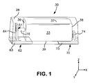
- FIG. 1 is a schematic illustration of one embodiment of a capacitor that may be formed in accordance with the present invention.
- FIG. 2 is a schematic illustration of a dielectric layer with a differential thickness in accordance with one embodiment of the present invention.
- the present invention is directed to a capacitor for use in relatively high voltage environments.
- the present inventors have discovered that the ability to achieve such voltages can be achieved through a unique and controlled combination of features relating to the formation of the anode, dielectric, and solid electrolyte.
- anodization may be carried out in a manner so that the dielectric layer possesses a relatively thick portion that overlies an external surface of the anode and a relatively thin portion that overlies an interior surface of the anode.
- it is believed that such a thickness distribution can help protect the anode at those external locations where oxide flaws are more vulnerable to current surges experienced at high voltages.
- the solid electrolyte is also formed from the combination of pre-polymerized conductive polymer particles and a hydroxy-functional nonionic polymer.
- the pre-polymerized particles can minimize the use of high energy radicals (e.g., Fe 2+ or Fe 3+ ions) that can otherwise lead to dielectric degradation, particularly at the high voltages noted above.
- high energy radicals e.g., Fe 2+ or Fe 3+ ions
- hydroxy-functional nonionic polymers can improve the degree of contact between the polymer particles and the surface of the internal dielectric, which is typically relatively smooth in nature as a result of higher forming voltages. This unexpectedly increases the breakdown voltage and wet-to-dry capacitance of the resulting capacitor.
- the resulting capacitor is able to be employed in high voltage applications.
- the capacitor may, for example, exhibit a relatively high “breakdown voltage” (voltage at which the capacitor fails), such as about 60 volts or more, in some embodiments about 70 volts or more, and in some embodiments about 80 volts or more.
- the capacitor may also be able to withstand relatively high surge currents, which is also common in high voltage applications.
- the peak surge current may be, for example, about 100 Amps or more, in some embodiments about 200 Amps or more, and in some embodiments, and in some embodiments, from about 300 Amps to about 800 Amps.
- the capacitor can also exhibit a relatively high percentage of its wet capacitance, which enables it to have only a small capacitance loss and/or fluctuation in the presence of atmosphere humidity.
- the capacitor of the present invention may exhibit a wet-to-dry capacitance percentage of about 50% or more, in some embodiments about 60% or more, in some embodiments about 70% or more, and in some embodiments, from about 80% to 100%.
- the anode is formed from a valve metal composition.
- the specific charge of the composition may vary, such as from about 2,000 ⁇ F*V/g to about 150,000 ⁇ F*V/g, in some embodiments from about 3,000 ⁇ F*V/g to about 70,000 ⁇ F*V/g or more, and in some embodiments, from about 4,000 to about 50,000 ⁇ F*V/g.
- the specific charge may be determined by multiplying capacitance by the anodizing voltage employed, and then dividing this product by the weight of the anodized electrode body.
- the valve metal composition generally contains a valve metal (i.e., metal that is capable of oxidation) or valve metal-based compound, such as tantalum, niobium, aluminum, hafnium, titanium, alloys thereof, oxides thereof, nitrides thereof, and so forth.
- the valve metal composition may contain an electrically conductive oxide of niobium, such as niobium oxide having an atomic ratio of niobium to oxygen of 1:1.0 ⁇ 1.0, in some embodiments 1:1.0 ⁇ 0.3, in some embodiments 1:1.0 ⁇ 0.1, and in some embodiments, 1:1.0 ⁇ 0.05.
- the niobium oxide may be NbO 0.7 , NbO 1.0 , NbO 1.1 , and NbO 2 .
- valve metal oxides are described in U.S. Pat. No. 6,322,912 to Fife; U.S. Pat. No. 6,391,275 to Fife et al.; U.S. Pat. No. 6,416,730 to Fife et al.; U.S. Pat. No. 6,527,937 to Fife; U.S. Pat. No. 6,576,099 to Kimmel, et al.; U.S. Pat. No. 6,592,740 to Fife, et al.; and U.S. Pat. No. 6,639,787 to Kimmel, et al.; and U.S. Pat. No.
- a powder of the valve metal composition is generally employed.
- the powder may contain particles any of a variety of shapes, such as nodular, angular, flake, etc., as well as mixtures thereof.
- the particles can have a flake-like morphology in that they possess a relatively flat or platelet shape.
- Such particles can provide a short transmission line between the outer surface and interior of the anode and also provide a highly continuous and dense wire-to-anode connection with high conductivity. Among other things, this may help increase the breakdown voltage (voltage at which the capacitor fails) and help lower equivalent series resistance (“ESR”).
- ESR equivalent series resistance
- the particles may also increase the specific charge of the anode when anodized at higher voltages, thereby increasing energy density.
- the flake particles When employed, the flake particles are generally flat.
- the degree of flatness is generally defined by the “aspect ratio”, i.e., the average diameter or width of the particles divided by the average thickness (“Da”).
- the aspect ratio of the particles may be from about 2 to about 100, in some embodiments from about 3 to about 50, in some embodiments, from about 4 to about 30.
- the particles may also have a specific surface area of from about 0.5 to about 10.0 m 2 /g, in some embodiments from about 0.7 to about 5.0 m 2 /g, and in some embodiments, from about 1.0 to about 4.0 m 2 /g.
- specific surface area generally refers to surface area as determined by the physical gas adsorption (B.E.T.) method of Bruanauer, Emmet, and Teller, Journal of American Chemical Society, Vol. 60, 1938, p. 309, with nitrogen as the adsorption gas.
- B.E.T. physical gas adsorption
- the test may be conducted with a MONOSORB® Specific Surface Area Analyzer available from QUANTACHROME Corporation, Syosset, N.Y., which measures the quantity of adsorbate nitrogen gas adsorbed on a solid surface by sensing the change in thermal conductivity of a flowing mixture of adsorbate and inert carrier gas (e.g., helium).
- the bulk density (also known as Scott density) is also typically from about 0.1 to about 2 grams per cubic centimeter (g/cm 3 ), in some embodiments from about 0.2 g/cm 3 to about 1.5 g/cm 3 , and in some embodiments, from about 0.4 g/cm 3 to about 1 g/cm 3 .
- “Bulk density” may be determined using a flow meter funnel and density cup. More specifically, the powder sample may be poured through the funnel into the cup until the sample completely fills and overflows the periphery of the cup, and thereafter sample may be leveled-off by a spatula, without jarring, so that it is flush with the top of the cup.
- the leveled sample is transferred to a balance and weighed to the nearest 0.1 gram to determine the density value.
- a balance is commercially available from Alcan Aluminum Corp. of Elizabeth, N.J.
- the particles may also have an average size (e.g., width) of from about 0.1 to about 100 micrometers, in some embodiments from about 0.5 to about 70 micrometers, and in some embodiments, from about 1 to about 50 micrometers.
- the powder may be optionally mixed with a binder and/or lubricant to ensure that the particles adequately adhere to each other when pressed to form the anode body.
- Suitable binders may include, for instance, poly(vinyl butyral); poly(vinyl acetate); poly(vinyl alcohol); poly(vinyl pyrrolidone); cellulosic polymers, such as carboxymethylcellulose, methyl cellulose, ethyl cellulose, hydroxyethyl cellulose, and methylhydroxyethyl cellulose; atactic polypropylene, polyethylene; polyethylene glycol (e.g., Carbowax from Dow Chemical Co.); polystyrene, poly(butadiene/styrene); polyamides, polyimides, and polyacrylamides, high molecular weight polyethers; copolymers of ethylene oxide and propylene oxide; fluoropolymers, such as polytetrafluoroethylene, polyvinylidene fluoride, and fluoro-olefin copolymers; acrylic polymers, such as sodium polyacrylate, poly(lower alkyl acrylates), poly(lower alkyl
- the binder may be dissolved and dispersed in a solvent.
- exemplary solvents may include water, alcohols, and so forth.
- the percentage of binders and/or lubricants may vary from about 0.1% to about 8% by weight of the total mass. It should be understood, however, that binders and/or lubricants are not necessarily required in the present invention.
- the resulting powder may then be compacted to form a pellet using any conventional powder press device.
- a press mold may be employed that is a single station compaction press containing a die and one or multiple punches.
- anvil-type compaction press molds may be used that use only a die and single lower punch.
- Single station compaction press molds are available in several basic types, such as cam, toggle/knuckle and eccentric/crank presses with varying capabilities, such as single action, double action, floating die, movable platen, opposed ram, screw, impact, hot pressing, coining or sizing.
- the powder may be compacted around an anode lead wire.
- the wire may be formed from any electrically conductive material, such as tantalum, niobium, aluminum, hafnium, titanium, etc., as well as electrically conductive oxides and/or nitrides of thereof.
- the resulting anode body may then be diced into any desired shape, such as square, rectangle, circle, oval, triangle, hexagon, octagon, heptagon, pentagon, etc.
- the anode body may also have a “fluted” shape in that it contains one or more furrows, grooves, depressions, or indentations to increase the surface to volume ratio to minimize ESR and extend the frequency response of the capacitance.
- the anode body may then be subjected to a heating step in which most, if not all, of any binder/lubricant are removed.
- the anode body is typically heated by an oven that operates at a temperature of from about 150° C. to about 500° C.
- the binder/lubricant may also be removed by contacting the pellet with an aqueous solution, such as described in U.S. Pat. No. 6,197,252 to Bishop, et al.
- the pellet is sintered to form a porous, integral mass.
- the temperature, atmosphere, and time of the sintering may depend on a variety of factors, such as the type of anode, the size of the anode, etc. Typically, sintering occurs at a temperature of from about from about 800° C. to about 1900° C., in some embodiments from about 1000° C. to about 1500° C., and in some embodiments, from about 1100° C. to about 1400° C., for a time of from about 5 minutes to about 100 minutes, and in some embodiments, from about 30 minutes to about 60 minutes. If desired, sintering may occur in an atmosphere that limits the transfer of oxygen atoms to the anode.
- sintering may occur in a reducing atmosphere, such as in a vacuum, inert gas, hydrogen, etc.
- the reducing atmosphere may be at a pressure of from about 10 Torr to about 2000 Torr, in some embodiments from about 100 Torr to about 1000 Torr, and in some embodiments, from about 100 Torr to about 930 Torr.
- Mixtures of hydrogen and other gases e.g., argon or nitrogen may also be employed.
- the anode may also have a relatively low carbon and oxygen content.
- the anode may have no more than about 50 ppm carbon, and in some embodiments, no more than about 10 ppm carbon.
- the anode may have no more than about 3500 ppm oxygen, in some embodiments no more than about 3000 ppm oxygen, and in some embodiments, from about 500 to about 2500 ppm oxygen.
- Oxygen content may be measured by LECO Oxygen Analyzer and includes oxygen in natural oxide on the tantalum surface and bulk oxygen in the tantalum particles. Bulk oxygen content is controlled by period of crystalline lattice of tantalum, which is increasing linearly with increasing oxygen content in tantalum until the solubility limit is achieved.
- Oxygen in sintered tantalum anodes may be limited to thin natural surface oxide, while the bulk of tantalum is practically free of oxygen.
- an anode lead may also be connected to the anode body that extends in a longitudinal direction therefrom.
- the anode lead may be in the form of a wire, sheet, etc., and may be formed from a valve metal compound, such as tantalum, niobium, niobium oxide, etc. Connection of the lead may be accomplished using known techniques, such as by welding the lead to the body or embedding it within the anode body during formation (e.g., prior to compaction and/or sintering).
- the dielectric layer of the capacitor possesses a differential thickness throughout the anode in that it possesses a first portion that overlies an external surface of the anode and a second portion that overlies an interior surface of the anode. As indicated above, the first portion is selectively formed so that its thickness is greater than that of the second portion. Without intending to be limited by theory, it is believed that such a thickness distribution can help protect the anode at those external locations where oxide flaws are more vulnerable to current surges experienced at high voltages. Referring to FIG. 2 , for instance, a schematic illustration of a section of an anodicially oxidized, porous anode body 200 is shown.
- the oxidized body 200 contains a dielectric layer 210 that overlies a sintered anode 202 with pores 209 .
- the anode 202 has an outer region 205 defined by an external surface 209 and an inner region 207 defined by an interior surface 211 .
- a dielectric layer 210 overlies both the outer region 205 and the inner region 207 of the anode 200 , with a first portion 220 being located adjacent to the external surface 209 and defining a first thickness “t 1 ”, and a second portion 230 being located adjacent to the interior surface 211 and defining a second thickness “t 2 .” As indicated, the first thickness “t 1 ” is greater than the second thickness “t 2 .” It should be understood, however, that the thickness of the dielectric layer need not be uniform within the inner or outer regions. Certain portions of the dielectric layer adjacent to the external surface may, for example, actually be thinner than certain portions of the layer at the interior surface, and vice versa.
- the dielectric layer is formed such that at least a portion of the layer at the external surface has a greater thickness than at least a portion at the interior surface.
- the ratio of the thickness of the first portion to the thickness of the second portion is typically from about 1.2 to about 40, in some embodiments from about 1.5 to about 25, and in some embodiments, from about 2 to about 20.
- a multi-stage process is generally employed.
- the sintered anode is anodically oxidized (“anodized”) to form a dielectric layer (e.g., tantalum pentoxide).
- Anodization is performed by initially applying an electrolyte to the anode, such as by dipping the anode into an electrolyte.
- the electrolyte is generally in the form of a liquid, such as a solution (e.g., aqueous or non-aqueous), dispersion, melt, etc.
- a solvent is generally employed in the electrolyte, such as water (e.g., deionized water); ethers (e.g., diethyl ether and tetrahydrofuran); alcohols (e.g., methanol, ethanol, n-propanol, isopropanol, and butanol); triglycerides; ketones (e.g., acetone, methyl ethyl ketone, and methyl isobutyl ketone); esters (e.g., ethyl acetate, butyl acetate, diethylene glycol ether acetate, and methoxypropyl acetate); amides (e.g., dimethylformamide, dimethylacetamide, dimethylcaprylic/capric fatty acid amide and N-alkylpyrrolidones); nitriles (e.g., acetonitrile, propionitrile, butyronitrile and benzonit
- the solvent may constitute from about 50 wt. % to about 99.9 wt. %, in some embodiments from about 75 wt. % to about 99 wt. %, and in some embodiments, from about 80 wt. % to about 95 wt. % of the electrolyte.
- an aqueous solvent e.g., water
- water may constitute about 1 wt. % or more, in some embodiments about 10 wt. % or more, in some embodiments about 50 wt. % or more, in some embodiments about 70 wt. % or more, and in some embodiments, about 90 wt. % to 100 wt. % of the solvent(s) used in the electrolyte.
- a current is passed through the electrolyte to form the dielectric, and the value of voltage manages the charge (current multiplied by time) and thereby the thickness of the dielectric layer.
- a relatively small forming voltage is typically employed to ensure that the desired dielectric thickness is achieved for the interior surface, such as forming voltages ranging from about 1 to about 90 volts, in some embodiments from about 2 to about 50 volts, and in some embodiments, from about 5 to about 20 volts.
- the sintered body may then be anodically oxidized in a second stage of the process to increase the thickness of the dielectric to the desired level.
- anodizing in an electrolyte at a higher voltage than employed during the first stage such as at forming voltages ranging from about 50 to about 350 volts, in some embodiments from about 60 to about 300 volts, and in some embodiments, from about 90 to about 200 volts.
- the electrolyte may be kept at a temperature within the range of from about 15° C. to about 95° C., in some embodiments from about 20° C. to about 90° C., and in some embodiments, from about 25° C. to about 85° C.
- the electrolytes employed during the first and second stages of the anodization process may be the same or different. Typically, however, it is desired to employ different solutions to help better facilitate the attainment of a higher thickness at the outer portions of the dielectric layer.
- the electrolyte employed in the second stage has a lower ionic conductivity than the electrolyte employed in the first stage to prevent a significant amount of oxide film from forming on the internal surface of anode.
- the electrolyte employed during the first stage may contain an acidic compound, such as hydrochloric acid, nitric acid, sulfuric acid, phosphoric acid, polyphosphoric acid, boric acid, boronic acid, etc.
- Such an electrolyte may have an electrical conductivity of from about 0.1 to about 100 mS/cm, in some embodiments from about 0.2 to about 20 mS/cm, and in some embodiments, from about 1 to about 10 mS/cm, determined at a temperature of 25° C.
- the electrolyte employed during the second stage typically contains a salt of a weak acid so that the hydronium ion concentration increases in the pores as a result of charge passage therein. Ion transport or diffusion is such that the weak acid anion moves into the pores as necessary to balance the electrical charges.
- Suitable weak acid salts may include, for instance, ammonium or alkali metal salts (e.g., sodium, potassium, etc.) of boric acid, boronic acid, acetic acid, oxalic acid, lactic acid, adipic acid, etc.
- Particularly suitable salts include sodium tetraborate and ammonium pentaborate.
- Such electrolytes typically have an electrical conductivity of from about 0.1 to about 20 mS/cm, in some embodiments from about 0.5 to about 10 mS/cm, and in some embodiments, from about 1 to about 5 mS/cm, determined at a temperature of 25° C.
- each stage of anodization may be repeated for one or more cycles to achieve the desired dielectric thickness.
- the anode may also be rinsed or washed with another solvent (e.g., water) after the first and/or second stages to remove the electrolyte.
- another solvent e.g., water
- a solid electrolyte overlies the dielectric that generally functions as the cathode for the capacitor.
- the solid electrolyte contains a conductive polymer, which is typically ⁇ -conjugated and has electrical conductivity after oxidation or reduction, such as an electrical conductivity of at least about 1 ⁇ S/cm.
- ⁇ -conjugated conductive polymers include, for instance, polyheterocycles (e.g., polypyrroles, polythiophenes, polyanilines, etc.), polyacetylenes, poly-p-phenylenes, polyphenolates, and so forth.
- the polymer is a substituted polythiophene, such as those having the following general structure:
- T O or S
- D is an optionally substituted C 1 to C 5 alkylene radical (e.g., methylene, ethylene, n-propylene, n-butylene, n-pentylene, etc.);
- R 7 is a linear or branched, optionally substituted C 1 to C 18 alkyl radical (e.g., methyl, ethyl, n- or iso-propyl, n-, iso-, sec- or tert-butyl, n-pentyl, 1-methylbutyl, 2-methylbutyl, 3-methylbutyl, 1-ethylpropyl, 1,1-dimethylpropyl, 1,2-dimethylpropyl, 2,2-dimethylpropyl, n-hexyl, n-heptyl, n-octyl, 2-ethylhexyl, n-nonyl, n-decyl, n-undecyl, n-dodecyl, n-tridecyl, n-tetradecyl, n-hexadecyl, n-octadecyl, etc.); optionally substituted C 5 to
- q is an integer from 0 to 8, in some embodiments, from 0 to 2, and in one embodiment, 0;
- n is from 2 to 5,000, in some embodiments from 4 to 2,000, and in some embodiments, from 5 to 1,000.
- substituents for the radicals “D” or “R 7 ” include, for instance, alkyl, cycloalkyl, aryl, aralkyl, alkoxy, halogen, ether, thioether, disulphide, sulfoxide, sulfone, sulfonate, amino, aldehyde, keto, carboxylic acid ester, carboxylic acid, carbonate, carboxylate, cyano, alkylsilane and alkoxysilane groups, carboxylamide groups, and so forth.
- Particularly suitable thiophene polymers are those in which “D” is an optionally substituted C 2 to C 3 alkylene radical.
- the polymer may be optionally substituted poly(3,4-ethylenedioxythiophene), which has the following general structure:
- T, D, R 7 , and q are defined above.
- Particularly suitable thiophene monomers are those in which “D” is an optionally substituted C 2 to C 3 alkylene radical.
- D is an optionally substituted C 2 to C 3 alkylene radical.
- optionally substituted 3,4-alkylenedioxythiophenes may be employed that have the general structure:
- R 7 and q are as defined above.
- “q” is 0.
- 3,4-ethylenedioxthiophene is available from H. C. Starck GmbH under the designation CleviosTM M.
- Other suitable monomers are also described in U.S. Pat. No. 5,111,327 to Blohm, et al. and U.S. Pat. No. 6,635,729 to Groenendaal, et al., which are incorporated herein in their entirety by reference thereto for all purposes. Derivatives of these monomers may also be employed that are, for example, dimers or trimers of the above monomers. Higher molecular derivatives, i.e., tetramers, pentamers, etc.
- the derivatives may be made up of identical or different monomer units and used in pure form and in a mixture with one another and/or with the monomers. Oxidized or reduced forms of these precursors may also be employed.
- the solid electrolyte generally includes a plurality of pre-polymerized particles applied in the form of a dispersion.
- a dispersion may minimize the presence of ionic species (e.g., Fe 2+ or Fe 3+ ) produced during in situ polymerization, which can cause dielectric breakdown under high electric field due to ionic migration.
- the resulting capacitor may exhibit a relatively high “breakdown voltage.”
- the particles employed in the dispersion typically have a small size, such as an average size (e.g., diameter) of from about 1 to about 150 nanometers, in some embodiments from about 2 to about 50 nanometers, and in some embodiments, from about 5 to about 40 nanometers.
- the diameter of the particles may be determined using known techniques, such as by ultracentrifuge, laser diffraction, etc.
- the shape of the particles may likewise vary. In one particular embodiment, for instance, the particles are spherical in shape.
- the concentration of the particles in the dispersion may vary depending on the desired viscosity of the dispersion and the particular manner in which the dispersion is to be applied to the capacitor. Typically, however, the particles constitute from about 0.1 to about 10 wt. %, in some embodiments from about 0.4 to about 5 wt. %, and in some embodiments, from about 0.5 to about 4 wt. % of the dispersion.
- the dispersion also generally contains a counterion that enhances the stability of the particles.
- the conductive polymer e.g., polythiophene or derivative thereof
- the conductive polymer typically has a charge on the main polymer chain that is neutral or positive (cationic).
- Polythiophene derivatives typically carry a positive charge in the main polymer chain.
- the polymer may possess positive and negative charges in the structural unit, with the positive charge being located on the main chain and the negative charge optionally on the substituents of the radical “R”, such as sulfonate or carboxylate groups.
- the positive charges of the main chain may be partially or wholly saturated with the optionally present anionic groups on the radicals “R.”
- the polythiophenes may, in these cases, be cationic, neutral or even anionic. Nevertheless, they are all regarded as cationic polythiophenes as the polythiophene main chain has a positive charge.
- the counterion may be a monomeric or polymeric anion that counteracts the charge of the conductive polymer.
- Polymeric anions can, for example, be anions of polymeric carboxylic acids (e.g., polyacrylic acids, polymethacrylic acid, polymaleic acids, etc.); polymeric sulfonic acids (e.g., polystyrene sulfonic acids (“PSS”), polyvinyl sulfonic acids, etc.); and so forth.
- the acids may also be copolymers, such as copolymers of vinyl carboxylic and vinyl sulfonic acids with other polymerizable monomers, such as acrylic acid esters and styrene.
- suitable monomeric anions include, for example, anions of C 1 to C 20 alkane sulfonic acids (e.g., dodecane sulfonic acid); aliphatic perfluorosulfonic acids (e.g., trifluoromethane sulfonic acid, perfluorobutane sulfonic acid or perfluorooctane sulfonic acid); aliphatic C 1 to C 20 carboxylic acids (e.g., 2-ethyl-hexylcarboxylic acid); aliphatic perfluorocarboxylic acids (e.g., trifluoroacetic acid or perfluorooctanoic acid); aromatic sulfonic acids optionally substituted by C 1 to C 20 alkyl groups (e.g., benzene sulfonic acid, o-toluene sulfonic acid, p-toluene sulfonic acid or dodecyl
- Particularly suitable counteranions are polymeric anions, such as a polymeric carboxylic or sulfonic acid (e.g., polystyrene sulfonic acid (“PSS”)).
- PSS polystyrene sulfonic acid
- the molecular weight of such polymeric anions typically ranges from about 1,000 to about 2,000,000, and in some embodiments, from about 2,000 to about 500,000.
- the weight ratio of such counterions to conductive polymers in the dispersion and in the resulting layer is typically from about 0.5:1 to about 50:1, in some embodiments from about 1:1 to about 30:1, and in some embodiments, from about 2:1 to about 20:1.
- the weight of the electrically conductive polymers corresponds referred to the above-referenced weight ratios refers to the weighed-in portion of the monomers used, assuming that a complete conversion occurs during polymerization.
- the dispersion may also contain one or more binders to further enhance the adhesive nature of the polymeric layer and also increase the stability of the particles within the dispersion.
- the binders may be organic in nature, such as polyvinyl alcohols, polyvinyl pyrrolidones, polyvinyl chlorides, polyvinyl acetates, polyvinyl butyrates, polyacrylic acid esters, polyacrylic acid amides, polymethacrylic acid esters, polymethacrylic acid amides, polyacrylonitriles, styrene/acrylic acid ester, vinyl acetate/acrylic acid ester and ethylene/vinyl acetate copolymers, polybutadienes, polyisoprenes, polystyrenes, polyethers, polyesters, polycarbonates, polyurethanes, polyamides, polyimides, polysulfones, melamine formaldehyde resins, ep
- Crosslinking agents may also be employed to enhance the adhesion capacity of the binders.
- Such crosslinking agents may include, for instance, melamine compounds, masked isocyanates or functional silanes, such as 3-glycidoxypropyltrialkoxysilane, tetraethoxysilane and tetraethoxysilane hydrolysate or crosslinkable polymers, such as polyurethanes, polyacrylates or polyolefins, and subsequent crosslinking.
- Dispersion agents may also be employed to facilitate the formation of the solid electrolyte and the ability to apply it to the anode part.
- Suitable dispersion agents include solvents, such as aliphatic alcohols (e.g., methanol, ethanol, i-propanol and butanol), aliphatic ketones (e.g., acetone and methyl ethyl ketones), aliphatic carboxylic acid esters (e.g., ethyl acetate and butyl acetate), aromatic hydrocarbons (e.g., toluene and xylene), aliphatic hydrocarbons (e.g., hexane, heptane and cyclohexane), chlorinated hydrocarbons (e.g., dichloromethane and dichloroethane), aliphatic nitriles (e.g., acetonitrile), aliphatic sulfoxides and sulfones (
- fillers may be used that have a size of from about 10 nanometers to about 100 micrometers, in some embodiments from about 50 nanometers to about 50 micrometers, and in some embodiments, from about 100 nanometers to about 30 micrometers.
- fillers include calcium carbonate, silicates, silica, calcium or barium sulfate, aluminum hydroxide, glass fibers or bulbs, wood flour, cellulose powder carbon black, electrically conductive polymers, etc.
- the fillers may be introduced into the dispersion in powder form, but may also be present in another form, such as fibers.
- Surface-active substances may also be employed in the dispersion, such as ionic or non-ionic surfactants.
- adhesives may be employed, such as organofunctional silanes or their hydrolysates, for example 3-glycidoxypropyltrialkoxysilane, 3-aminopropyl-triethoxysilane, 3-mercaptopropyl-trimethoxysilane, 3-metacryloxypropyltrimethoxysilane, vinyltrimethoxysilane or octyltriethoxysilane.
- the dispersion may also contain additives that increase conductivity, such as ether group-containing compounds (e.g., tetrahydrofuran), lactone group-containing compounds (e.g., ⁇ -butyrolactone or ⁇ -valerolactone), amide or lactam group-containing compounds (e.g., caprolactam, N-methylcaprolactam, N,N-dimethylacetamide, N-methylacetamide, N,N-dimethylformamide (DMF), N-methylformamide, N-methylformanilide, N-methylpyrrolidone (NMP), N-octylpyrrolidone, or pyrrolidone), sulfones and sulfoxides (e.g., sulfolane (tetramethylenesulfone) or dimethylsulfoxide (DMSO)), sugar or sugar derivatives (e.g., saccharose, glucose, fructose, or lactose), sugar alcohols (e
- the polymeric dispersion may be applied using a variety of known techniques, such as by spin coating, impregnation, pouring, dropwise application, injection, spraying, doctor blading, brushing, printing (e.g., ink-jet, screen, or pad printing), or dipping.
- the viscosity of the dispersion is typically from about 0.1 to about 100,000 mPas (measured at a shear rate of 100 s ⁇ 1 ), in some embodiments from about 1 to about 10,000 mPas, in some embodiments from about 10 to about 1,600 mPas, and in some embodiments, from about 100 to about 1000 mPas.
- the layer may be dried and/or washed.
- One or more additional layers may also be formed in this manner to achieve the desired thickness.
- the total thickness of the layer(s) formed by this particle dispersion is from about 1 to about 50 ⁇ m, and in some embodiments, from about 5 to about 20 ⁇ m.
- the weight ratio of counterions to conductive polymers is likewise from about 0.5:1 to about 50:1, in some embodiments from about 1:1 to about 30:1, and in some embodiments, from about 2:1 to about 20:1.
- the solid electrolyte also contains a hydroxy-functional nonionic polymer.
- hydroxy-functional generally means that the compound contains at least one hydroxyl functional group or is capable of possessing such a functional group in the presence of a solvent. Without intending to be limited by theory, it is believed that hydroxy-functional nonionic polymers can improve the degree of contact between the polymer particles and the surface of the internal dielectric, which is typically relatively smooth in nature as a result of higher forming voltages. This unexpectedly increases the breakdown voltage and wet-to-dry capacitance of the resulting capacitor.
- the use of a hydroxy-functional polymer with a certain molecular weight can also minimize the likelihood of chemical decomposition at high voltages.
- the molecular weight of the hydroxy-functional polymer may be from about 100 to 10,000 grams per mole, in some embodiments from about 200 to 2,000, in some embodiments from about 300 to about 1,200, and in some embodiments, from about 400 to about 800.
- the hydroxy-functional polymer is a polyalkylene ether.
- Polyalkylene ethers may include polyalkylene glycols (e.g., polyethylene glycols, polypropylene glycols polytetramethylene glycols, polyepichlorohydrins, etc.), polyoxetanes, polyphenylene ethers, polyether ketones, and so forth. Polyalkylene ethers are typically predominantly linear, nonionic polymers with terminal hydroxy groups.
- polyethylene glycols polypropylene glycols and polytetramethylene glycols (polytetrahydrofurans), which are produced by polyaddition of ethylene oxide, propylene oxide or tetrahydrofuran onto water.
- the polyalkylene ethers may be prepared by polycondensation reactions from diols or polyols.
- the diol component may be selected, in particular, from saturated or unsaturated, branched or unbranched, aliphatic dihydroxy compounds containing 5 to 36 carbon atoms or aromatic dihydroxy compounds, such as, for example, pentane-1,5-diol, hexane-1,6-diol, neopentyl glycol, bis-(hydroxymethyl)-cyclohexanes, bisphenol A, dimer diols, hydrogenated dimer diols or even mixtures of the diols mentioned.
- polyhydric alcohols may also be used in the polymerization reaction, including for example glycerol, di- and polyglycerol, trimethylolpropane, pentaerythritol or sorbitol.
- hydroxy-functional nonionic polymers may also be employed in the present invention.
- Some examples of such polymers include, for instance, ethoxylated alkylphenols; ethoxylated or propoxylated C 6 -C 24 fatty alcohols; polyoxyethylene glycol alkyl ethers having the general formula: CH 3 —(CH 2 ) 10-16 —(O—C 2 H 4 ) 1-25 —OH (e.g., octaethylene glycol monododecyl ether and pentaethylene glycol monododecyl ether); polyoxypropylene glycol alkyl ethers having the general formula: CH 3 —(CH 2 ) 10-16 —(O—C 3 H 6 ) 1-25 —OH; polyoxyethylene glycol octylphenol ethers having the following general formula: C 8 —H 17 —(C 6 H 4 )—(O—C 2 H 4 ) 1-25 —OH (e.g.,
- the hydroxy-functional nonionic polymer may be incorporated into the solid electrolyte in a variety of different ways.
- the hydroxy-functional polymer may simply be incorporated into any layer(s) formed by the initial dispersion described above.
- the concentration of the hydroxy-functional polymer in the dispersion is typically from about 1 wt. % to about 50 wt. %, in some embodiments from about 5 wt. % to about 40 wt. %, and in some embodiments, from about 10 wt. % to about 30 wt. %.
- the hydroxy-functional polymer may be applied after the initial polymer dispersion is applied to the anode body.
- the technique used to apply the hydroxy-functional polymer may vary.
- the polymer may be applied in the form of a liquid solution using various methods, such as immersion, dipping, pouring, dripping, injection, spraying, spreading, painting or printing, for example, inkjet, screen printing or tampon printing.
- Solvents known to the person skilled in the art can be employed in the solution, such as water, alcohols, or a mixture thereof.
- the concentration of the hydroxy-functional polymer in such a solution typically ranges from about 5 wt. % to about 95 wt.
- conductive polymers may constitute about 2 wt. % or less, in some embodiments about 1 wt. % or less, and in some embodiments, about 0.5 wt. % or less of the solution.
- a second polymer dispersion that contains conductive polymer particles and a hydroxy-functional polymer is applied to the anode after the initial layer(s) formed from the first polymer dispersion are applied to the anode body.
- the conductive particles of the second polymer dispersion are generally described above, although they need not be identical to those employed in the first polymer dispersion.
- the first and second polymer dispersion may employ particles of a different size and/or chemical composition.
- the concentration of the hydroxy-functional polymer in the second polymer dispersion is typically from about 1 wt.
- hydroxy-functional polymer may constitute about 2 wt. % or less, in some embodiments about 1 wt. % or less, and in some embodiments, about 0.5 wt. % or less of the first polymer dispersion.
- the layer formed by the second polymer dispersion may be dried and/or washed.
- One or more additional layers may also be formed in this manner to achieve the desired thickness.
- the total thickness of the layers formed by the second polymer dispersion is from about 0.1 to about 5 ⁇ m, in some embodiments from about 0.1 to about 3 ⁇ m, and in some embodiments, from about 0.2 to about 1 ⁇ m.
- an external polymer coating may also be applied to the anode body and overlie the solid electrolyte.
- the external polymer coating generally contains one or more layers formed from a dispersion of pre-polymerized conductive particles, such as described in more detail above.
- the external coating may be able to penetrate into the edge region of the capacitor body to increase the adhesion to the dielectric. This results in a more mechanically robust part, which may reduce equivalent series resistance and leakage current. Because it is generally intended to improve the degree of edge coverage rather to impregnate the interior of the anode, the particles used in the external coating typically have a larger size than those employed in the initial dispersion of the solid electrolyte.
- the ratio of the average size of the particles employed in the external polymer coating to the average size of the particles employed in the initial dispersion of the solid electrolyte is typically from about 1.5 to about 30, in some embodiments from about 2 to about 20, and in some embodiments, from about 5 to about 15.
- the particles employed in the dispersion of the external coating may have an average size of from about 50 to about 500 nanometers, in some embodiments from about 80 to about 250 nanometers, and in some embodiments, from about 100 to about 200 nanometers.
- a crosslinking agent may also be employed in the external polymer coating to enhance the degree of adhesion to the solid electrolyte.
- the crosslinking agent is applied prior to application of the dispersion used in the external coating. Suitable crosslinking agents are described, for instance, in U.S. Patent Publication No. 2007/0064376 to Merker, et al.
- amines e.g., diamines, triamines, oligomer amines, polyamines, etc.
- polyvalent metal cations such as salts or compounds of Mg, Al, Ca, Fe, Cr, Mn, Ba, Ti, Co, Ni, Cu, Ru, Ce or Zn, phosphonium compounds, sulfonium compounds, etc.
- Particularly suitable examples include, for instance, 1,4-diaminocyclohexane, 1,4-bis(amino-methyl)cyclohexane, ethylenediamine, 1,6-hexanediamine, 1,7-heptanediamine, 1,8-octanediamine, 1,9-nonanediamine, 1,10-decanediamine, 1,12-dodecanediamine, N,N-dimethylethylenediamine, N,N,N′,N′-tetramethylethylenediamine, N,N,N′,N′-tetramethyl-1,4-butanediamine, etc., as well as mixtures thereof.
- the crosslinking agent is typically applied from a solution or dispersion whose pH is from 1 to 10, in some embodiments from 2 to 7, in some embodiments, from 3 to 6, as determined at 25° C. Acidic compounds may be employed to help achieve the desired pH level.
- solvents or dispersants for the crosslinking agent include water or organic solvents, such as alcohols, ketones, carboxylic esters, etc.
- the crosslinking agent may be applied to the capacitor body by any known process, such as spin-coating, impregnation, casting, dropwise application, spray application, vapor deposition, sputtering, sublimation, knife-coating, painting or printing, for example inkjet, screen or pad printing.
- the crosslinking agent may be dried prior to application of the polymer dispersion. This process may then be repeated until the desired thickness is achieved.
- the total thickness of the entire external polymer coating, including the crosslinking agent and dispersion layers may range from about 1 to about 50 ⁇ m, in some embodiments from about 2 to about 40 ⁇ m, and in some embodiments, from about 5 to about 20 ⁇ m.
- the capacitor may also contain other layers as is known in the art.
- a protective coating may optionally be formed between the dielectric and solid electrolyte, such as one made of a relatively insulative resinous material (natural or synthetic).
- Such materials may have a specific resistivity of greater than about 10 ⁇ cm, in some embodiments greater than about 100, in some embodiments greater than about 1,000 ⁇ cm, in some embodiments greater than about 1 ⁇ 10 5 ⁇ cm, and in some embodiments, greater than about 1 ⁇ 10 10 ⁇ cm.
- Some resinous materials that may be utilized in the present invention include, but are not limited to, polyurethane, polystyrene, esters of unsaturated or saturated fatty acids (e.g., glycerides), and so forth.
- suitable esters of fatty acids include, but are not limited to, esters of lauric acid, myristic acid, palmitic acid, stearic acid, eleostearic acid, oleic acid, linoleic acid, linolenic acid, aleuritic acid, shellolic acid, and so forth. These esters of fatty acids have been found particularly useful when used in relatively complex combinations to form a “drying oil”, which allows the resulting film to rapidly polymerize into a stable layer.
- drying oils may include mono-, di-, and/or tri-glycerides, which have a glycerol backbone with one, two, and three, respectively, fatty acyl residues that are esterified.
- suitable drying oils include, but are not limited to, olive oil, linseed oil, castor oil, tung oil, soybean oil, and shellac.
- the capacitor may also be provided with terminations, particularly when employed in surface mounting applications.
- the capacitor may contain an anode termination to which the anode lead of the capacitor element is electrically connected and a cathode termination to which the cathode of the capacitor element is electrically connected.
- Any conductive material may be employed to form the terminations, such as a conductive metal (e.g., copper, nickel, silver, nickel, zinc, tin, palladium, lead, copper, aluminum, molybdenum, titanium, iron, zirconium, magnesium, and alloys thereof).
- Particularly suitable conductive metals include, for instance, copper, copper alloys (e.g., copper-zirconium, copper-magnesium, copper-zinc, or copper-iron), nickel, and nickel alloys (e.g., nickel-iron).
- the thickness of the terminations is generally selected to minimize the thickness of the capacitor. For instance, the thickness of the terminations may range from about 0.05 to about 1 millimeter, in some embodiments from about 0.05 to about 0.5 millimeters, and from about 0.07 to about 0.2 millimeters.
- One exemplary conductive material is a copper-iron alloy metal plate available from Wieland (Germany).
- the surface of the terminations may be electroplated with nickel, silver, gold, tin, etc. as is known in the art to ensure that the final part is mountable to the circuit board. In one particular embodiment, both surfaces of the terminations are plated with nickel and silver flashes, respectively, while the mounting surface is also plated with a tin solder layer.
- an electrolytic capacitor 30 that includes an anode termination 62 and a cathode termination 72 in electrical connection with a capacitor element 33 .
- the capacitor element 33 has an upper surface 37 , lower surface 39 , front surface 36 , and rear surface 38 . Although it may be in electrical contact with any of the surfaces of the capacitor element 33 , the cathode termination 72 in the illustrated embodiment is in electrical contact with the lower surface 39 and rear surface 38 . More specifically, the cathode termination 72 contains a first component 73 positioned substantially perpendicular to a second component 74 . The first component 73 is in electrical contact and generally parallel with the lower surface 39 of the capacitor element 33 .
- the second component 74 is in electrical contact and generally parallel to the rear surface 38 of the capacitor element 33 . Although depicted as being integral, it should be understood that these portions may alternatively be separate pieces that are connected together, either directly or via an additional conductive element (e.g., metal).
- additional conductive element e.g., metal
- the anode termination 62 likewise contains a first component 63 positioned substantially perpendicular to a second component 64 .
- the first component 63 is in electrical contact and generally parallel with the lower surface 39 of the capacitor element 33 .
- the second component 64 contains a region 51 that carries an anode lead 16 .
- the region 51 possesses a “U-shape” for further enhancing surface contact and mechanical stability of the lead 16 .
- the terminations may be connected to the capacitor element using any technique known in the art.
- a lead frame may be provided that defines the cathode termination 72 and anode termination 62 .
- a conductive adhesive may initially be applied to a surface of the cathode termination 72 .
- the conductive adhesive may include, for instance, conductive metal particles contained with a resin composition.
- the metal particles may be silver, copper, gold, platinum, nickel, zinc, bismuth, etc.
- the resin composition may include a thermoset resin (e.g., epoxy resin), curing agent (e.g., acid anhydride), and coupling agent (e.g., silane coupling agents).
- Suitable conductive adhesives may be described in U.S. Patent Application Publication No. 2006/0038304 to Osako, et al., which is incorporated herein in its entirety by reference thereto for all purposes. Any of a variety of techniques may be used to apply the conductive adhesive to the cathode termination 72 . Printing techniques, for instance, may be employed due to their practical and cost-saving benefits.
- the second component 64 of the anode termination 62 and the second component 74 of the cathode termination 72 are initially bent upward to the position shown in FIG. 1 . Thereafter, the capacitor element 33 is positioned on the cathode termination 72 so that its lower surface 39 contacts the adhesive and the anode lead 16 is received by the upper U-shaped region 51 .
- an insulating material (not shown), such as a plastic pad or tape, may be positioned between the lower surface 39 of the capacitor element 33 and the first component 63 of the anode termination 62 to electrically isolate the anode and cathode terminations.
- the anode lead 16 is then electrically connected to the region 51 using any technique known in the art, such as mechanical welding, laser welding, conductive adhesives, etc.
- the anode lead 16 may be welded to the anode termination 62 using a laser.
- Lasers generally contain resonators that include a laser medium capable of releasing photons by stimulated emission and an energy source that excites the elements of the laser medium.
- One type of suitable laser is one in which the laser medium consist of an aluminum and yttrium garnet (YAG), doped with neodymium (Nd).
- the excited particles are neodymium ions Nd 3+ .
- the energy source may provide continuous energy to the laser medium to emit a continuous laser beam or energy discharges to emit a pulsed laser beam.
- the conductive adhesive may then be cured.
- a heat press may be used to apply heat and pressure to ensure that the electrolytic capacitor element 33 is adequately adhered to the cathode termination 72 by the adhesive.
- the lead frame is enclosed within a resin casing, which may then be filled with silica or any other known encapsulating material.
- the width and length of the case may vary depending on the intended application. Suitable casings may include, for instance, “A”, “B”, “C”, “D”, “E”, “F”, “G”, “H”, “J”, “K”, “L”, “M”, “N”, “P”, “R”, “S”, “T”, “V”, “W”, “Y”, “X”, or “Z” (AVX Corporation).
- the capacitor element is encapsulated so that at least a portion of the anode and cathode terminations are exposed for mounting onto a circuit board. As shown in FIG. 1 , for instance, the capacitor element 33 is encapsulated in a case 28 so that a portion of the anode termination 62 and a portion of the cathode termination 72 are exposed.
- the capacitor assembly may exhibit excellent electrical properties even when exposed to high temperature environments.
- the capacitor assembly may have an equivalence series resistance (“ESR”) of less than about 100 mohms, in some embodiments less than about 75 mohms, in some embodiments from about 0.01 to about 60 mohms, and in some embodiments, from about 0.05 to about 50 mohms, measured at an operating frequency of 100 kHz.
- ESR equivalence series resistance
- the leakage current which generally refers to the current flowing from one conductor to an adjacent conductor through an insulator, can be maintained at relatively low levels.
- the numerical value of the normalized leakage current of a capacitor of the present invention is, in some embodiments, less than about 1 ⁇ A/ ⁇ F*V, in some embodiments less than about 0.5 ⁇ A/ ⁇ F*V, and in some embodiments, less than about 0.1 ⁇ A/ ⁇ F*V, where ⁇ A is microamps and uF*V is the product of the capacitance and the rated voltage.
- ESR and normalized leakage current values may even be maintained after aging for a substantial amount of time at high temperatures.
- the values may be maintained for about 100 hours or more, in some embodiments from about 300 hours to about 3000 hours, and in some embodiments, from about 400 hours to about 2500 hours (e.g., 500 hours, 600 hours, 700 hours, 800 hours, 900 hours, 1000 hours, 1100 hours, 1200 hours, or 2000 hours) at temperatures ranging from about 50° C. to about 250° C., and, in some embodiments from about 70° C. to about 225° C., and in some embodiments, from about 100° C. to about 225° C. (e.g., 100° C., 125° C., 150° C., 175° C., or 200° C.).
- 500 hours, 600 hours, 700 hours, 800 hours, 900 hours, 1000 hours, 1100 hours, 1200 hours, or 2000 hours at temperatures ranging from about 50° C. to about 250° C., and, in some embodiments from about 70° C. to about 225° C., and in some embodiments, from about 100° C. to about 225°
- the capacitor may also exhibit a high energy density that enables it suitable for use in high pulse applications.
- the capacitance may, for instance, be measured using a capacitance meter (e.g., Keithley 3330 Precision LCZ meter with Kelvin Leads, 2 volts bias and 1 volt signal) at an operating frequency of 120 Hz and a temperature of 25° C.
- a capacitance meter e.g., Keithley 3330 Precision LCZ meter with Kelvin Leads, 2 volts bias and 1 volt signal
- the capacitor may exhibit an energy density of about 2.0 joules per cubic centimeter (J/cm 3 ) or more, in some embodiments about 3.0 J/cm 3 , in some embodiments from about 4.0 J/cm 3 to about 10.0 J/cm 3 , and in some embodiments, from about 4.5 to about 8.0 J/cm 3 .
- the capacitance may likewise be about 1 milliFarad per square centimeter (“mF/cm 2 ”) or more, in some embodiments about 2 mF/cm 2 or more, in some embodiments from about 5 to about 50 mF/cm 2 , and in some embodiments, from about 8 to about 20 mF/cm 2 .
- Equivalence series resistance may be measured using a Keithley 3330 Precision LCZ meter with Kelvin Leads 2.2 volt DC bias and a 0.5 volt peak to peak sinusoidal signal.
- the operating frequency was 100 kHz and the temperature was room temperature.
- the capacitance was measured using a Keithley 3330 Precision LCZ meter with Kelvin Leads with 2.2 volt DC bias and a 0.5 volt peak to peak sinusoidal signal. The operating frequency was 120 Hz and the temperature was room temperature.
- the “dry capacitance” refers to the capacitance of the part after application of the solid electrolyte, graphite, and silver layers, while the “wet capacitance” refers to the capacitance of the part after formation of the dielectric, measured in 17% sulfuric acid in reference to 1 mF tantalum cathode.
- 70,000 ⁇ FV/g tantalum powder was used to form anode samples.
- Each anode sample was embedded with a tantalum wire, sintered at 1280° C., and pressed to a density of 6.8 g/cm 3 .
- the resulting pellets had a size of 1.80 ⁇ 1.20 ⁇ 2.40 mm.
- the pellets were anodized to 14.4V in water/phosphoric acid electrolyte with conductivity 8.6 mS at temperature of 85° C. to form the dielectric layer.
- a conductive polymer coating was then formed by dipping the anodes into a dispersed poly(3,4-ethylenedioxythiophene) having a solids content 1.1% and viscosity 20 mPa ⁇ s (CleviosTM K, H. C. Starck). Upon coating, the parts were dried at 125° C. for 20 minutes. This process was repeated 10 times. Thereafter, the parts were dipped into a dispersed poly(3,4-ethylenedioxythiophene) having a solids content 2% and viscosity 20 mPa ⁇ s (CleviosTM K, H. C. Starck). Upon coating, the parts were dried at 125° C. for 20 minutes. This process was not repeated.
- the parts were dipped into a dispersed poly(3,4-ethylenedioxythiophene) having a solids content 2% and viscosity 160 mPa ⁇ s (CleviosTM K, H. C. Starck). Upon coating, the parts were dried at 125° C. for 20 minutes. This process was repeated 8 times. The parts were then dipped into a graphite dispersion and dried. Finally, the parts were dipped into a silver dispersion and dried. Multiple parts (200) of 150 ⁇ F/6.3V capacitors were made in this manner.
- 70,000 pFV/g tantalum powder was used to form anode samples.
- Each anode sample was embedded with a tantalum wire, sintered at 1280° C., and pressed to a density of 6.8 g/cm 3 .
- the resulting pellets had a size of 1.80 ⁇ 1.20 ⁇ 2.40 mm.
- the pellets were anodized to 14.4V in water/phosphoric acid electrolyte with conductivity 8.6 mS at temperature of 85° C. to form the dielectric layer.
- the pellets were anodized again to 60V in water/boric acid/disodium tetraborate with conductivity 2.0 mS at temperature of 30° C. for 25 seconds to form a thicker oxide layer built up on the outside.
- a conductive polymer coating, graphite coating, silver coating was then formed in the same manner described in Example 1. Multiple parts (200) of 150 ⁇ F/6.3V capacitors were made in this manner.
- Capacitors were formed in the manner described in Example 2, except using a different conductive polymer coating.
- a conductive polymer coating was formed by dipping the anodes into a dispersed poly(3,4-ethylenedioxythiophene) having a solids content 1.1% and viscosity 20 mPa ⁇ s (CleviosTM K, H. C. Starck). Upon coating, the parts were dried at 125° C. for 20 minutes. This process was repeated 10 times. Thereafter, the parts were dipped into a dispersed poly(3,4-ethylenedioxythiophene) having a solids content 2% and viscosity 20 mPa ⁇ s (CleviosTM K, H. C.
- Capacitors were formed in the manner described in Example 2, except using a different conductive polymer coating.
- a conductive polymer coating was formed by dipping the anodes into a dispersed poly(3,4-ethylenedioxythiophene) having a solids content 1.1% and viscosity 20 mPa ⁇ s (CleviosTM K, H. C. Starck). Upon coating, the parts were dried at 125° C. for 20 minutes. This process was repeated 10 times. Thereafter, the parts were dipped into a aqueous solution having a solids content 20% of poly(ethylene glycol) with molecular weight 600 (Sigma Aldrich®). Upon coating, the parts were dried at 125° C. for 20 minutes. This process was not repeated.
- the parts were dipped into a dispersed poly(3,4-ethylenedioxythiophene) having a solids content 2% and viscosity 20 mPa ⁇ s (CleviosTM K, H. C. Starck). Upon coating, the parts were dried at 125° C. for 20 minutes. This process was not repeated. Thereafter, the parts were dipped into a dispersed poly(3,4-ethylenedioxythiophene) having a solids content 2% and viscosity 160 mPa ⁇ s (CleviosTM K, H. C. Starck). Upon coating, the parts were dried at 125° C. for 20 minutes. This process was repeated 8 times. The parts were then dipped into a graphite dispersion and dried. Finally, the parts were dipped into a silver dispersion and dried. Multiple parts (200) of 150 ⁇ F/6.3V capacitors were made in this manner.
- the finished capacitors of Examples 1-4 were then tested for electrical performance before an assembly process.
- the median results of capacitance, dissipation factor (Df), and ESR are set forth below in Table 1.
- the wet capacitance was 145.0 ⁇ F in all examples.
- Example 3 and 4 which also contained polyethylene glycol, had a higher dry/wet capacitance value than the shell-formed part of Example 2, which did not contain polyethylene glycol.
Landscapes
- Engineering & Computer Science (AREA)
- Chemical & Material Sciences (AREA)
- Chemical Kinetics & Catalysis (AREA)
- Electrochemistry (AREA)
- Power Engineering (AREA)
- Microelectronics & Electronic Packaging (AREA)
- Manufacturing & Machinery (AREA)
- Conductive Materials (AREA)
- Compositions Of Macromolecular Compounds (AREA)
- Polyoxymethylene Polymers And Polymers With Carbon-To-Carbon Bonds (AREA)
Priority Applications (1)
| Application Number | Priority Date | Filing Date | Title |
|---|---|---|---|
| US13/941,693 US9406445B2 (en) | 2012-07-19 | 2013-07-15 | Solid electrolytic capacitor with enhanced wet-to-dry capacitance |
Applications Claiming Priority (2)
| Application Number | Priority Date | Filing Date | Title |
|---|---|---|---|
| US201261673409P | 2012-07-19 | 2012-07-19 | |
| US13/941,693 US9406445B2 (en) | 2012-07-19 | 2013-07-15 | Solid electrolytic capacitor with enhanced wet-to-dry capacitance |
Publications (2)
| Publication Number | Publication Date |
|---|---|
| US20140022702A1 US20140022702A1 (en) | 2014-01-23 |
| US9406445B2 true US9406445B2 (en) | 2016-08-02 |
Family
ID=49880037
Family Applications (1)
| Application Number | Title | Priority Date | Filing Date |
|---|---|---|---|
| US13/941,693 Active 2034-07-27 US9406445B2 (en) | 2012-07-19 | 2013-07-15 | Solid electrolytic capacitor with enhanced wet-to-dry capacitance |
Country Status (4)
| Country | Link |
|---|---|
| US (1) | US9406445B2 (ja) |
| JP (3) | JP6630466B2 (ja) |
| CN (1) | CN103578778B (ja) |
| DE (1) | DE102013213723A1 (ja) |
Cited By (18)
| Publication number | Priority date | Publication date | Assignee | Title |
|---|---|---|---|---|
| US10186382B2 (en) | 2016-01-18 | 2019-01-22 | Avx Corporation | Solid electrolytic capacitor with improved leakage current |
| US10622160B2 (en) | 2017-03-06 | 2020-04-14 | Avx Corporation | Solid electrolytic capacitor assembly |
| US10741333B2 (en) | 2016-10-18 | 2020-08-11 | Avx Corporation | Solid electrolytic capacitor with improved leakage current |
| US10770238B2 (en) | 2017-07-03 | 2020-09-08 | Avx Corporation | Solid electrolytic capacitor assembly with hydrophobic coatings |
| US10892095B2 (en) | 2016-10-18 | 2021-01-12 | Avx Corporation | Solid electrolytic capacitor assembly |
| US11114250B2 (en) | 2018-08-10 | 2021-09-07 | Avx Corporation | Solid electrolytic capacitor formed from conductive polymer particles |
| US11183342B2 (en) | 2018-08-10 | 2021-11-23 | Avx Corporation | Solid electrolytic capacitor containing polyaniline |
| US11257628B2 (en) | 2017-07-03 | 2022-02-22 | KYOCERA AVX Components Corporation | Solid electrolytic capacitor containing a nanocoating |
| US11387047B2 (en) | 2016-10-18 | 2022-07-12 | KYOCERA AVX Components Corporation | Solid electrolytic capacitor with improved performance at high temperatures and voltages |
| US11462366B2 (en) | 2018-08-10 | 2022-10-04 | KYOCERA AVX Components Corporation | Solid electrolytic capacitor containing an intrinsically conductive polymer |
| US11631548B2 (en) | 2020-06-08 | 2023-04-18 | KYOCERA AVX Components Corporation | Solid electrolytic capacitor containing a moisture barrier |
| US11670461B2 (en) | 2019-09-18 | 2023-06-06 | KYOCERA AVX Components Corporation | Solid electrolytic capacitor for use at high voltages |
| US11763998B1 (en) | 2020-06-03 | 2023-09-19 | KYOCERA AVX Components Corporation | Solid electrolytic capacitor |
| US11776759B2 (en) | 2019-12-10 | 2023-10-03 | KYOCER AVX Components Corporation | Tantalum capacitor with increased stability |
| US11823846B2 (en) | 2019-12-10 | 2023-11-21 | KYOCERA AVX Components Corporation | Solid electrolytic capacitor containing a pre-coat and intrinsically conductive polymer |
| US11837415B2 (en) | 2021-01-15 | 2023-12-05 | KYOCERA AVX Components Corpration | Solid electrolytic capacitor |
| US11955294B2 (en) | 2018-12-11 | 2024-04-09 | KYOCERA AVX Components Corporation | Solid electrolytic capacitor containing an intrinsically conductive polymer |
| US12002631B2 (en) | 2021-10-20 | 2024-06-04 | KYOCERA AVX Components Corporation | Electrodeposited dielectric for a solid electrolytic capacitor |
Families Citing this family (18)
| Publication number | Priority date | Publication date | Assignee | Title |
|---|---|---|---|---|
| DE102013213720A1 (de) | 2012-07-19 | 2014-01-23 | Avx Corporation | Temperaturstabiler Festelektrolytkondensator |
| DE102013213728A1 (de) | 2012-07-19 | 2014-01-23 | Avx Corporation | Nichtionisches Tensid zur Verwendung in einem festen Elektrolyten eines Elektrolytkondensators |
| US9548163B2 (en) | 2012-07-19 | 2017-01-17 | Avx Corporation | Solid electrolytic capacitor with improved performance at high voltages |
| GB2512480B (en) | 2013-03-13 | 2018-05-30 | Avx Corp | Solid electrolytic capacitor for use in extreme conditions |
| US10074487B2 (en) * | 2015-05-18 | 2018-09-11 | Avx Corporation | Solid electrolytic capacitor having a high capacitance |
| US9991055B2 (en) * | 2015-05-29 | 2018-06-05 | Avx Corporation | Solid electrolytic capacitor assembly for use at high temperatures |
| US9672989B2 (en) | 2015-05-29 | 2017-06-06 | Avx Corporation | Solid electrolytic capacitor assembly for use in a humid atmosphere |
| US9972444B2 (en) | 2015-05-29 | 2018-05-15 | Avx Corporation | Solid electrolytic capacitor element for use in dry conditions |
| US9767963B2 (en) | 2015-05-29 | 2017-09-19 | Avx Corporation | Solid electrolytic capacitor with an ultrahigh capacitance |
| JP2017174915A (ja) * | 2016-03-23 | 2017-09-28 | カーリットホールディングス株式会社 | 導電性高分子分散液及びそれを用いた固体電解コンデンサの製造方法 |
| US10763046B2 (en) * | 2016-09-15 | 2020-09-01 | Avx Corporation | Solid electrolytic capacitor with improved leakage current |
| JP6851907B2 (ja) * | 2017-05-31 | 2021-03-31 | 株式会社トーキン | 固体電解コンデンサの製造方法 |
| US10943742B2 (en) * | 2017-10-18 | 2021-03-09 | Kemet Electronics Corporation | Conductive polymer dispersion for improved reliability |
| CN111048314B (zh) * | 2018-10-12 | 2021-11-26 | 钰冠科技股份有限公司 | 抗突波电容器及其制造方法 |
| US11380492B1 (en) * | 2018-12-11 | 2022-07-05 | KYOCERA AVX Components Corporation | Solid electrolytic capacitor |
| US11328874B2 (en) * | 2019-05-17 | 2022-05-10 | KYOCERA AVX Components Corporation | Solid electrolytic capacitor |
| JP7441106B2 (ja) * | 2019-06-10 | 2024-02-29 | ケメット エレクトロニクス コーポレーション | 信頼性の改善のための導電性ポリマー分散液 |
| JPWO2021192607A1 (ja) * | 2020-03-27 | 2021-09-30 |
Citations (67)
| Publication number | Priority date | Publication date | Assignee | Title |
|---|---|---|---|---|
| US3440495A (en) | 1966-11-07 | 1969-04-22 | Mallory & Co Inc P R | Hermetically sealed electrolytic capacitor |
| US3922773A (en) | 1974-07-17 | 1975-12-02 | Corning Glass Works | Method of forming a hermetic enclosure |
| US4131520A (en) | 1977-11-10 | 1978-12-26 | Sprague Electric Company | Two-stage anodization of capacitor electrodes |
| US4278513A (en) | 1980-06-30 | 1981-07-14 | Sprague Electric Company | Two-stage differential anodization process |
| US4479168A (en) | 1983-12-19 | 1984-10-23 | Sprague Electric Company | Electrolytic capacitor with a hermetic seal |
| US4508563A (en) | 1984-03-19 | 1985-04-02 | Sprague Electric Company | Reducing the oxygen content of tantalum |
| US4910645A (en) | 1988-04-30 | 1990-03-20 | Bayer Aktiengesellschaft | Solid electrolytes, and electrolyte capacitors containing same |
| US5457862A (en) | 1993-11-10 | 1995-10-17 | Nec Corporation | Method of manufacturing solid electrolytic capacitor |
| US5473503A (en) | 1993-07-27 | 1995-12-05 | Nec Corporation | Solid electrolytic capacitor and method for manufacturing the same |
| US5560761A (en) | 1994-09-28 | 1996-10-01 | Starck Vtech Ltd. | Tantalum powder and electrolytic capacitor using same |
| US5586000A (en) | 1993-12-28 | 1996-12-17 | Nec Corporation | Solid electrolytic capacitor and process for production thereof |
| US5643432A (en) | 1995-07-13 | 1997-07-01 | Avx Corporation | Selective anodization of capacitor anode body |
| US5694287A (en) | 1994-09-02 | 1997-12-02 | Nec Corporation | Solid electrolytic capacitor with conductive polymer as solid electrolyte and method of manufacturing the same |
| US5729428A (en) | 1995-04-25 | 1998-03-17 | Nec Corporation | Solid electrolytic capacitor with conductive polymer as solid electrolyte and method for fabricating the same |
| US6231993B1 (en) | 1998-10-01 | 2001-05-15 | Wilson Greatbatch Ltd. | Anodized tantalum pellet for an electrolytic capacitor |
| US6238456B1 (en) * | 1997-02-19 | 2001-05-29 | H. C. Starck Gmbh & Co. Kg | Tantalum powder, method for producing same powder and sintered anodes obtained from it |
| US6261434B1 (en) | 1999-10-19 | 2001-07-17 | Kemet Electronics Corporation | Differential anodization process for electrolytic capacitor anode bodies |
| US6350406B1 (en) | 1999-11-04 | 2002-02-26 | Nec Corporation | Method of manufacturing anode unit for solid electrolytic capacitor, anode unit for solid electrolytic capacitor, continuous sintering apparatus, and method of manufacturing secondary particles of valve-action metal powder |
| US6674635B1 (en) | 2001-06-11 | 2004-01-06 | Avx Corporation | Protective coating for electrolytic capacitors |
| US6798644B1 (en) | 2003-07-10 | 2004-09-28 | Kemet Electronics Corporation | ESR of solid electrolytic capacitors using conductive polymer cathodes |
| US6804109B1 (en) | 2003-10-20 | 2004-10-12 | Kemet Electronics Corporation | Solid electrolyte capacitor having transition metal oxide underlayer and conductive polymer electrolyte |
| JP2005340714A (ja) * | 2004-05-31 | 2005-12-08 | Nichicon Corp | 固体電解コンデンサの製造方法 |
| US6987663B2 (en) | 2003-10-17 | 2006-01-17 | H.C. Starck Gmbh | Electrolytic capacitors with a polymeric outer layer |
| US7118690B2 (en) | 2000-11-22 | 2006-10-10 | H. C. Starck Gmbh | Dispersible polymer powders |
| US7221554B2 (en) | 2003-05-21 | 2007-05-22 | Kemet Electronics Corporation | Method of electrolytic deposition of an intrinsically conductive polymer upon a non-conductive substrate |
| US7279015B2 (en) | 2004-05-05 | 2007-10-09 | H.C. Starck Gmbh | Process for the producing of electrolytic capacitors |
| US7304832B2 (en) | 2005-02-23 | 2007-12-04 | Kyocera Corporation | Ceramic container and battery and electric double layer capacitor using the same |
| US7377947B2 (en) | 2005-04-11 | 2008-05-27 | H.C. Starck Gmbh | Electrolyte capacitors having a polymeric outer layer and process for their production |
| US7411779B2 (en) | 2005-07-20 | 2008-08-12 | H.C. Starck Gmbh | Electrolytic capacitors with a polymeric outer layer and process for the production thereof |
| US7515396B2 (en) | 2007-03-21 | 2009-04-07 | Avx Corporation | Solid electrolytic capacitor containing a conductive polymer |
| US7563290B2 (en) | 2006-07-06 | 2009-07-21 | Kemet Electronics Corporation | High voltage solid electrolytic capacitors using conductive polymer slurries |
| US7679885B2 (en) | 2006-05-05 | 2010-03-16 | Cabot Corporation | Tantalum powder and methods of manufacturing same |
| US7750099B2 (en) | 2004-07-12 | 2010-07-06 | H. C. Starck Gmbh | Method for producing an aqueous dispersion containing a complex of poly(3,4-dialkoxythiophene) and a polyanion |
| US7785493B2 (en) | 2005-11-10 | 2010-08-31 | H. C. Starck Gmbh & Co. Kg | Polymer coatings having improved resistance to solvents |
| US20110019339A1 (en) | 2007-10-08 | 2011-01-27 | H.C. Starck Clevios Gmbh | Method for the production of electrolyte capacitors with polymer intermediate layer |
| US7898794B2 (en) | 2004-10-08 | 2011-03-01 | H. C. Starck Gmbh | Tantalum powder for the production of solid electrolyte capacitors |
| US7948069B2 (en) | 2004-01-28 | 2011-05-24 | International Rectifier Corporation | Surface mountable hermetically sealed package |
| US7973180B2 (en) | 2005-11-17 | 2011-07-05 | H.C. Starck Gmbh | Process for producing aqueous dispersion of composite of poly(3,4-dialkoxythiophene) with polyanion |
| US7972534B2 (en) | 2003-04-02 | 2011-07-05 | H. C. Starck Gmbh | Retarding oxidants for preparing conductive polymers |
| US20110168946A1 (en) | 2008-05-09 | 2011-07-14 | H.C. Starck Clevios Gmbh | Novel polythiophene polyanion complexes in homopolar organic solvents |
| US8058135B2 (en) | 2005-09-13 | 2011-11-15 | H. C. Starck Gmbh | Process for the production of electrolyte capacitors |
| US8094434B2 (en) | 2008-04-01 | 2012-01-10 | Avx Corporation | Hermetically sealed capacitor assembly |
| US20120057275A1 (en) | 2009-02-05 | 2012-03-08 | H.C. Starck Clevios Gmbh | Process for producing electrolytic capacitors with a polymeric outer layer |
| US20120063063A1 (en) | 2010-09-15 | 2012-03-15 | Kemet Electronics Corporation | Process for solid electrolytic capacitors using polymer slurries |
| WO2012041506A2 (en) | 2010-10-01 | 2012-04-05 | Heraeus Precious Metals Gmbh & Co. Kg | A method for improving electrical parameters in capacitors comprising pedot/pss as a solid electrolyte through a polyalkylene glycol |
| WO2012048824A1 (en) | 2010-10-12 | 2012-04-19 | Heraeus Precious Metals Gmbh & Co. Kg | Dispersions comprising polythiophenes with a defined sulfate content |
| US20120106031A1 (en) | 2010-11-01 | 2012-05-03 | Avx Corporation | Solid Electrolytic Capacitor for Use in High Voltage and High Temperature Applications |
| US8194395B2 (en) | 2009-10-08 | 2012-06-05 | Avx Corporation | Hermetically sealed capacitor assembly |
| US20120206860A1 (en) | 2011-02-15 | 2012-08-16 | Qingping Chen | Process for producing electrolytic capacitors and capacitors made thereby |
| WO2012119711A1 (en) | 2011-03-06 | 2012-09-13 | Heraeus Precious Metals Gmbh & Co. Kg | Method for improving the electrical parameters in capacitors containing pedot/pss as a solid electrolyte by polyglycerol |
| US8279584B2 (en) | 2010-08-12 | 2012-10-02 | Avx Corporation | Solid electrolytic capacitor assembly |
| WO2012136305A1 (en) | 2011-04-08 | 2012-10-11 | Heraeus Precious Metals Gmbh & Co. Kg | Process for improving the electrical parameters in capacitors comprising pedot/pss as solid electrolyte, by means of additives |
| US8310815B2 (en) | 2009-04-20 | 2012-11-13 | Kemet Electronics Corporation | High voltage and high efficiency polymer electrolytic capacitors |
| US8308825B2 (en) | 2008-05-12 | 2012-11-13 | Kemet Electronics Corporation | High volumetric efficiency anodes for electrolytic capacitors |
| US8313538B2 (en) | 2005-09-13 | 2012-11-20 | Heraeus Precious Metals Gmbh & Co. Kg | Process for the production of electrolyte capacitors of high nominal voltage |
| US8349030B1 (en) | 2011-09-21 | 2013-01-08 | Kemet Electronics Corporation | Method for making anodes for high voltage electrolytic capacitors with high volumetric efficiency and stable D.C. leakage |
| US20130070393A1 (en) | 2010-03-31 | 2013-03-21 | Nozomu Kamiyama | Solid electrolytic capacitor |
| US8456803B2 (en) | 2008-07-11 | 2013-06-04 | Heraeus Precious Metals Gmbh & Co. Kg | Method for production of electrolyte capacitors |
| US20130261261A1 (en) | 2010-10-12 | 2013-10-03 | Heraeus Precious Metals Gmbh & Co. Kg | Dispersions Comprising Polythiophenes With A Defined Content Of Thiophene Monomer |
| US20130279079A1 (en) * | 2010-10-01 | 2013-10-24 | Heraeus Precious Metals Gmbh & Co. Kg | Method for improving electrical parameters in capacitors comprising pedot/pss as a solid electrolyte through a polyalkylene glycol |
| US20130295389A1 (en) | 2010-10-01 | 2013-11-07 | Herarus Precious Metals GmbH & Co. KG | Layer compositions with improved electrical parameters comprising pedot/pss and a stabilizer |
| US20130300370A1 (en) | 2011-01-26 | 2013-11-14 | Sony Corporation | Battery pack and electric power consuming apparatus |
| US20140022704A1 (en) | 2012-07-19 | 2014-01-23 | Avx Corporation | Solid Electrolytic Capacitor with Improved Performance at High Voltages |
| US20140022703A1 (en) | 2012-07-19 | 2014-01-23 | Avx Corporation | Temperature Stable Solid Electrolytic Capacitor |
| US20140078646A1 (en) | 2012-02-27 | 2014-03-20 | Kemet Electronics Corporation | Solid Electrolytic Capacitor with Interlayer Crosslinking |
| US20140340819A1 (en) | 2013-05-17 | 2014-11-20 | Kemet Electronics Corporation | Solid Electrolytic Capacitor and Improved Method for Manufacturing a Solid Electrolytic Capacitor |
| US20150029642A1 (en) | 2013-07-24 | 2015-01-29 | Kemet Electronics Corporation | Conductive Polymer Composition with a Dual Crosslinker System for Capacitors |
Family Cites Families (16)
| Publication number | Priority date | Publication date | Assignee | Title |
|---|---|---|---|---|
| JPS58147023A (ja) * | 1982-02-25 | 1983-09-01 | 日本電気ホームエレクトロニクス株式会社 | 固体電解コンデンサの製造方法 |
| US5111327A (en) | 1991-03-04 | 1992-05-05 | General Electric Company | Substituted 3,4-polymethylenedioxythiophenes, and polymers and electro responsive devices made therefrom |
| GB9700566D0 (en) | 1997-01-13 | 1997-03-05 | Avx Ltd | Binder removal |
| US6391275B1 (en) | 1998-09-16 | 2002-05-21 | Cabot Corporation | Methods to partially reduce a niobium metal oxide and oxygen reduced niobium oxides |
| US6322912B1 (en) | 1998-09-16 | 2001-11-27 | Cabot Corporation | Electrolytic capacitor anode of valve metal oxide |
| US6416730B1 (en) | 1998-09-16 | 2002-07-09 | Cabot Corporation | Methods to partially reduce a niobium metal oxide oxygen reduced niobium oxides |
| DE10004725A1 (de) | 2000-02-03 | 2001-08-09 | Bayer Ag | Verfahren zur Herstellung von wasserlöslichen pi-konjugierten Polymeren |
| US6576099B2 (en) | 2000-03-23 | 2003-06-10 | Cabot Corporation | Oxygen reduced niobium oxides |
| JP2004513514A (ja) | 2000-11-06 | 2004-04-30 | キャボット コーポレイション | 酸素を低減した改質バルブ金属酸化物 |
| JP2008182056A (ja) * | 2007-01-25 | 2008-08-07 | Nichicon Corp | 固体電解コンデンサ |
| JP5340708B2 (ja) * | 2008-11-28 | 2013-11-13 | 三洋電機株式会社 | 固体電解コンデンサ |
| JP5273726B2 (ja) * | 2009-04-07 | 2013-08-28 | Necトーキン株式会社 | 固体電解コンデンサおよびその製造方法 |
| JP5495311B2 (ja) * | 2010-01-21 | 2014-05-21 | Necトーキン株式会社 | 固体電解コンデンサおよびその製造方法 |
| JP2011253878A (ja) * | 2010-06-01 | 2011-12-15 | Holy Stone Polytech Co Ltd | 固体電解コンデンサ |
| US8619410B2 (en) * | 2010-06-23 | 2013-12-31 | Avx Corporation | Solid electrolytic capacitor for use in high voltage applications |
| US8355242B2 (en) * | 2010-11-12 | 2013-01-15 | Avx Corporation | Solid electrolytic capacitor element |
-
2013
- 2013-07-12 DE DE102013213723.0A patent/DE102013213723A1/de active Pending
- 2013-07-15 US US13/941,693 patent/US9406445B2/en active Active
- 2013-07-17 CN CN201310301663.2A patent/CN103578778B/zh active Active
- 2013-07-18 JP JP2013149328A patent/JP6630466B2/ja active Active
-
2018
- 2018-02-23 JP JP2018030619A patent/JP2018110256A/ja active Pending
-
2019
- 2019-11-14 JP JP2019205970A patent/JP2020025136A/ja active Pending
Patent Citations (70)
| Publication number | Priority date | Publication date | Assignee | Title |
|---|---|---|---|---|
| US3440495A (en) | 1966-11-07 | 1969-04-22 | Mallory & Co Inc P R | Hermetically sealed electrolytic capacitor |
| US3922773A (en) | 1974-07-17 | 1975-12-02 | Corning Glass Works | Method of forming a hermetic enclosure |
| US4131520A (en) | 1977-11-10 | 1978-12-26 | Sprague Electric Company | Two-stage anodization of capacitor electrodes |
| US4278513A (en) | 1980-06-30 | 1981-07-14 | Sprague Electric Company | Two-stage differential anodization process |
| US4479168A (en) | 1983-12-19 | 1984-10-23 | Sprague Electric Company | Electrolytic capacitor with a hermetic seal |
| US4508563A (en) | 1984-03-19 | 1985-04-02 | Sprague Electric Company | Reducing the oxygen content of tantalum |
| US4910645A (en) | 1988-04-30 | 1990-03-20 | Bayer Aktiengesellschaft | Solid electrolytes, and electrolyte capacitors containing same |
| US5473503A (en) | 1993-07-27 | 1995-12-05 | Nec Corporation | Solid electrolytic capacitor and method for manufacturing the same |
| US5457862A (en) | 1993-11-10 | 1995-10-17 | Nec Corporation | Method of manufacturing solid electrolytic capacitor |
| US5586000A (en) | 1993-12-28 | 1996-12-17 | Nec Corporation | Solid electrolytic capacitor and process for production thereof |
| US5694287A (en) | 1994-09-02 | 1997-12-02 | Nec Corporation | Solid electrolytic capacitor with conductive polymer as solid electrolyte and method of manufacturing the same |
| US5560761A (en) | 1994-09-28 | 1996-10-01 | Starck Vtech Ltd. | Tantalum powder and electrolytic capacitor using same |
| US5729428A (en) | 1995-04-25 | 1998-03-17 | Nec Corporation | Solid electrolytic capacitor with conductive polymer as solid electrolyte and method for fabricating the same |
| US5643432A (en) | 1995-07-13 | 1997-07-01 | Avx Corporation | Selective anodization of capacitor anode body |
| US6238456B1 (en) * | 1997-02-19 | 2001-05-29 | H. C. Starck Gmbh & Co. Kg | Tantalum powder, method for producing same powder and sintered anodes obtained from it |
| US6231993B1 (en) | 1998-10-01 | 2001-05-15 | Wilson Greatbatch Ltd. | Anodized tantalum pellet for an electrolytic capacitor |
| US6261434B1 (en) | 1999-10-19 | 2001-07-17 | Kemet Electronics Corporation | Differential anodization process for electrolytic capacitor anode bodies |
| US6350406B1 (en) | 1999-11-04 | 2002-02-26 | Nec Corporation | Method of manufacturing anode unit for solid electrolytic capacitor, anode unit for solid electrolytic capacitor, continuous sintering apparatus, and method of manufacturing secondary particles of valve-action metal powder |
| US7118690B2 (en) | 2000-11-22 | 2006-10-10 | H. C. Starck Gmbh | Dispersible polymer powders |
| US6674635B1 (en) | 2001-06-11 | 2004-01-06 | Avx Corporation | Protective coating for electrolytic capacitors |
| US7972534B2 (en) | 2003-04-02 | 2011-07-05 | H. C. Starck Gmbh | Retarding oxidants for preparing conductive polymers |
| US7221554B2 (en) | 2003-05-21 | 2007-05-22 | Kemet Electronics Corporation | Method of electrolytic deposition of an intrinsically conductive polymer upon a non-conductive substrate |
| US6798644B1 (en) | 2003-07-10 | 2004-09-28 | Kemet Electronics Corporation | ESR of solid electrolytic capacitors using conductive polymer cathodes |
| US6987663B2 (en) | 2003-10-17 | 2006-01-17 | H.C. Starck Gmbh | Electrolytic capacitors with a polymeric outer layer |
| US6804109B1 (en) | 2003-10-20 | 2004-10-12 | Kemet Electronics Corporation | Solid electrolyte capacitor having transition metal oxide underlayer and conductive polymer electrolyte |
| US7948069B2 (en) | 2004-01-28 | 2011-05-24 | International Rectifier Corporation | Surface mountable hermetically sealed package |
| US7279015B2 (en) | 2004-05-05 | 2007-10-09 | H.C. Starck Gmbh | Process for the producing of electrolytic capacitors |
| JP2005340714A (ja) * | 2004-05-31 | 2005-12-08 | Nichicon Corp | 固体電解コンデンサの製造方法 |
| US7750099B2 (en) | 2004-07-12 | 2010-07-06 | H. C. Starck Gmbh | Method for producing an aqueous dispersion containing a complex of poly(3,4-dialkoxythiophene) and a polyanion |
| US7898794B2 (en) | 2004-10-08 | 2011-03-01 | H. C. Starck Gmbh | Tantalum powder for the production of solid electrolyte capacitors |
| US7304832B2 (en) | 2005-02-23 | 2007-12-04 | Kyocera Corporation | Ceramic container and battery and electric double layer capacitor using the same |
| US7377947B2 (en) | 2005-04-11 | 2008-05-27 | H.C. Starck Gmbh | Electrolyte capacitors having a polymeric outer layer and process for their production |
| US7411779B2 (en) | 2005-07-20 | 2008-08-12 | H.C. Starck Gmbh | Electrolytic capacitors with a polymeric outer layer and process for the production thereof |
| US8313538B2 (en) | 2005-09-13 | 2012-11-20 | Heraeus Precious Metals Gmbh & Co. Kg | Process for the production of electrolyte capacitors of high nominal voltage |
| US8058135B2 (en) | 2005-09-13 | 2011-11-15 | H. C. Starck Gmbh | Process for the production of electrolyte capacitors |
| US7785493B2 (en) | 2005-11-10 | 2010-08-31 | H. C. Starck Gmbh & Co. Kg | Polymer coatings having improved resistance to solvents |
| US7973180B2 (en) | 2005-11-17 | 2011-07-05 | H.C. Starck Gmbh | Process for producing aqueous dispersion of composite of poly(3,4-dialkoxythiophene) with polyanion |
| US7679885B2 (en) | 2006-05-05 | 2010-03-16 | Cabot Corporation | Tantalum powder and methods of manufacturing same |
| US7990683B2 (en) | 2006-07-06 | 2011-08-02 | Kemet Electronics Corporation | High voltage solid electrolytic capacitors using conductive polymer slurries |
| US7563290B2 (en) | 2006-07-06 | 2009-07-21 | Kemet Electronics Corporation | High voltage solid electrolytic capacitors using conductive polymer slurries |
| US7515396B2 (en) | 2007-03-21 | 2009-04-07 | Avx Corporation | Solid electrolytic capacitor containing a conductive polymer |
| US20110019339A1 (en) | 2007-10-08 | 2011-01-27 | H.C. Starck Clevios Gmbh | Method for the production of electrolyte capacitors with polymer intermediate layer |
| US8094434B2 (en) | 2008-04-01 | 2012-01-10 | Avx Corporation | Hermetically sealed capacitor assembly |
| US20110168946A1 (en) | 2008-05-09 | 2011-07-14 | H.C. Starck Clevios Gmbh | Novel polythiophene polyanion complexes in homopolar organic solvents |
| US8308825B2 (en) | 2008-05-12 | 2012-11-13 | Kemet Electronics Corporation | High volumetric efficiency anodes for electrolytic capacitors |
| US8456803B2 (en) | 2008-07-11 | 2013-06-04 | Heraeus Precious Metals Gmbh & Co. Kg | Method for production of electrolyte capacitors |
| US20120057275A1 (en) | 2009-02-05 | 2012-03-08 | H.C. Starck Clevios Gmbh | Process for producing electrolytic capacitors with a polymeric outer layer |
| US8310815B2 (en) | 2009-04-20 | 2012-11-13 | Kemet Electronics Corporation | High voltage and high efficiency polymer electrolytic capacitors |
| US8323361B2 (en) | 2009-04-20 | 2012-12-04 | Kemet Electronics Corporation | High voltage and high efficiency polymer electrolytic capacitors |
| US8194395B2 (en) | 2009-10-08 | 2012-06-05 | Avx Corporation | Hermetically sealed capacitor assembly |
| US20130070393A1 (en) | 2010-03-31 | 2013-03-21 | Nozomu Kamiyama | Solid electrolytic capacitor |
| US8279584B2 (en) | 2010-08-12 | 2012-10-02 | Avx Corporation | Solid electrolytic capacitor assembly |
| US20120063063A1 (en) | 2010-09-15 | 2012-03-15 | Kemet Electronics Corporation | Process for solid electrolytic capacitors using polymer slurries |
| US20130279079A1 (en) * | 2010-10-01 | 2013-10-24 | Heraeus Precious Metals Gmbh & Co. Kg | Method for improving electrical parameters in capacitors comprising pedot/pss as a solid electrolyte through a polyalkylene glycol |
| US20130295389A1 (en) | 2010-10-01 | 2013-11-07 | Herarus Precious Metals GmbH & Co. KG | Layer compositions with improved electrical parameters comprising pedot/pss and a stabilizer |
| WO2012041506A2 (en) | 2010-10-01 | 2012-04-05 | Heraeus Precious Metals Gmbh & Co. Kg | A method for improving electrical parameters in capacitors comprising pedot/pss as a solid electrolyte through a polyalkylene glycol |
| US20130261261A1 (en) | 2010-10-12 | 2013-10-03 | Heraeus Precious Metals Gmbh & Co. Kg | Dispersions Comprising Polythiophenes With A Defined Content Of Thiophene Monomer |
| WO2012048824A1 (en) | 2010-10-12 | 2012-04-19 | Heraeus Precious Metals Gmbh & Co. Kg | Dispersions comprising polythiophenes with a defined sulfate content |
| US20120106031A1 (en) | 2010-11-01 | 2012-05-03 | Avx Corporation | Solid Electrolytic Capacitor for Use in High Voltage and High Temperature Applications |
| US20130300370A1 (en) | 2011-01-26 | 2013-11-14 | Sony Corporation | Battery pack and electric power consuming apparatus |
| US20120206860A1 (en) | 2011-02-15 | 2012-08-16 | Qingping Chen | Process for producing electrolytic capacitors and capacitors made thereby |
| US9030807B2 (en) | 2011-02-15 | 2015-05-12 | Kemet Electronics Corporation | Materials and methods for improving corner and edge coverage of solid electrolytic capacitors |
| WO2012119711A1 (en) | 2011-03-06 | 2012-09-13 | Heraeus Precious Metals Gmbh & Co. Kg | Method for improving the electrical parameters in capacitors containing pedot/pss as a solid electrolyte by polyglycerol |
| WO2012136305A1 (en) | 2011-04-08 | 2012-10-11 | Heraeus Precious Metals Gmbh & Co. Kg | Process for improving the electrical parameters in capacitors comprising pedot/pss as solid electrolyte, by means of additives |
| US8349030B1 (en) | 2011-09-21 | 2013-01-08 | Kemet Electronics Corporation | Method for making anodes for high voltage electrolytic capacitors with high volumetric efficiency and stable D.C. leakage |
| US20140078646A1 (en) | 2012-02-27 | 2014-03-20 | Kemet Electronics Corporation | Solid Electrolytic Capacitor with Interlayer Crosslinking |
| US20140022704A1 (en) | 2012-07-19 | 2014-01-23 | Avx Corporation | Solid Electrolytic Capacitor with Improved Performance at High Voltages |
| US20140022703A1 (en) | 2012-07-19 | 2014-01-23 | Avx Corporation | Temperature Stable Solid Electrolytic Capacitor |
| US20140340819A1 (en) | 2013-05-17 | 2014-11-20 | Kemet Electronics Corporation | Solid Electrolytic Capacitor and Improved Method for Manufacturing a Solid Electrolytic Capacitor |
| US20150029642A1 (en) | 2013-07-24 | 2015-01-29 | Kemet Electronics Corporation | Conductive Polymer Composition with a Dual Crosslinker System for Capacitors |
Non-Patent Citations (37)
| Title |
|---|
| Abstract of Japanese Patent-JP2001257130, Sep. 21, 2001, 2 pages. |
| Abstract of Japanese Patent-JP2010090397, Apr. 22, 2010, 1 page. |
| Abstract of Japanese Patent-JPH01140621, Jun. 1, 1989, 1 page. |
| Abstract of Japanese Patent-JPH03109712, May 9, 1991, 2 pages. |
| Abstract of Japanese Patent-JPH03109713, May 9, 1991, 2 pages. |
| Abstract of Japanese Patent-JPH03109714, May 9, 1991, 2 pages. |
| Abstract of Japanese Patent-JPH03127813, May 30, 1991, 1 page. |
| Abstract of WO Patent-WO2010015468, Feb. 11, 2010, 1 page. |
| Article-Balaji et al., "Sintering and electrical properties of tantalum anodes for capacitor applications," Materials Letters, vol. 56, 2002, pp. 560-563. |
| Article-Freeman et al., "Critical oxygen content in porous anodes of solid tantalum capacitors," Journal of Materials Science: Materials in Electronics, vol. 9, 1998, pp. 309-311. |
| Article-Helmut Haas, "Magnesium Vapour Reduced Tantalum Powders with Very High Capacitances," CARTS Europe 2004, 18th Annual Passive Components Conference, Oct. 18, 21, 2004, 4, pages. |
| Article-Pozdeev-Freeman et al., "Critical oxygen content in porous anodes of solid tantalum capacitors," Journal of Materials Science: Materials in Electronics, vol. 9, 1998, pp. 309-311. |
| Article-Simkins et al, "Tantalum Powders for High Voltage Applications II," CARTS 2004, 24th Annual Capacitor and Resistor Technology Symposium, Mar. 29-Apr. 1, 2004. |
| Machine Translation of Japanese Patent-JP2005217129, Aug. 11, 2005, 11 pages. |
| Material Safety Data Sheet from MetLab Corporation on Polyethylene Glycol, 7 pages, Jan. 2011. |
| Paper-Bates et al., "Reaching the Highest Reliability for Tantalum Capacitors," CARTS International 2013, Mar. 25-28, 2013, 12 pages. |
| Paper-Freeman et al, "How High Working Voltage Can Go in Polymer Tantalum Capacitors," CARTS USA 2011, Jacksonville, Florida, Mar. 28-31, 2011, 15 pages. |
| Paper-Freeman et al., "Electrical Characterization of Polymer Tantalum Capacitors with Poly(3,4-Ethylenedioxythiophene) Cathode," Journal of the Electrochemical Society, vol. 156, No. 6, 2009, 10 pages and CARTS Europe 2008, Helsinki, Finland, Oct. 20-23, 2008. |
| Paper-Freeman et al., "How Far We Can Go with Hi CV Ta Capacitors," CARTS Europe 2004, 18th Annual Passive Components Conference, Oct. 18-21, 2004. |
| Paper-Freeman et al., "Low Voltage CV Loss in Tantalum Capacitors," CARTS USA 2010, New Orleans, LA, Mar. 16, 2010, 12 pages. |
| Paper-Freeman et al., "Reliability and Critical Applications of Tantalum Capacitors," CARTS Europe 2007 Symposium, Oct.-Nov. 2007, Barcelona, Spain, pp. 193-204. |
| Paper-Freeman, et al., "Stable, Reliable, and Efficient Tantalum Capacitors," CARTS USA 2008, 28th Symposium, for Passive Electronics, March, Newport Beach, California, 6 pages. |
| Paper-Merker et al., "Conducting Polymer Dispersions for High-Capacitance Tantalum Capacitors,", CARTS Europe 2006, Sep. 2006, Bad Homburg, Germany, 6 pages. |
| Paper-Merker et al., "New Conducting Polymer Dispersions for Solid Electrolytic Capacitors," CARTS Europe 2005, Oct. 17-20, 2005, Prague, CZ Republic, 6 pages. |
| Paper-Merker et al., "Tuning Conducting Polymer Dispersions for High-CV Tantalum Capacitors," CARTS Europe Oct. 29-Nov. 1, 2007, Barcelona, Spain, 6 pages. |
| Paper-Petrzilek et al., "Hermetically Sealed SMD Tantalum Capacitors," CARTS USA 2012, 6 pages. |
| Paper-Petrzilek et al., "Next Generation of High Voltage, Low ESR Tantalum Conductive Polymer Capacitors," CARTS USA 2011, Jacksonville, Florida, Mar. 28-31, 2011, 9 pages. |
| Paper-Simpson et al., "Advances and Applications of Inherently Conductive Polymer Technologies Based on Poly(3,4-Ethylenedioxythiophene)," 2005 AIMCAL Fall Technical Conference and 19th International Vacuum Web Coating Conference , Oct. 16-20, 2005, Session 5: Advances in Technology, Myrtle Beach, SC, 10 pages. |
| Paper-Young et al., "High Voltage Tantalum Polymer Capacitors," CARTS Europe 2008, Helsinki, Finland, Oct. 20-23, 2008. |
| Paper-Young et al., "Performance and Reliability Study of High Voltage Tantalum Polymer Capacitors," 2010 Electronic Components Association, Inc., Arlington, VA; CARTS 2010 Conference Proceedings, CARTS 2010 Conference, New Orleans, LA, Apr. 2010, 13 pages. |
| Paper-Zednicek et al, "Hermetically Sealed 230C MnO2 Tantalum Capacitors," CARTS International 2013, Mar. 25-28, 2013, 8 pages. |
| Presentation-Freeman et al., "Hermetically Sealed Polymer Tantalum Capacitors," CMSE Europe 2010. |
| Press Release-AVX's New 125V Tantalum Polymer SMD Capacitors Surpass Previous 100V Milestone, Jun. 24, 2013, 2 pages. |
| Product Information for Tantalum Polvmer Through-Hole Capacitors, T550 Polymer Hermetic Seal (PHS) Series, from Kemet, 2011, 2 pages. |
| Related Application Form. |
| Thesis-Brian Holman, "The Electrical Characterization of Tantalum Capacitors as MIS Devices," Aug. 2008, Clemson University, 128 pages. |
| Thesis-Githin Francis Alapatt, "Investigating Pre-Breakdown Currents in Poiymer Tantalum Capacitors," Aug. 2010, Clemson University, 102 pages. |
Cited By (21)
| Publication number | Priority date | Publication date | Assignee | Title |
|---|---|---|---|---|
| US10186382B2 (en) | 2016-01-18 | 2019-01-22 | Avx Corporation | Solid electrolytic capacitor with improved leakage current |
| US10741333B2 (en) | 2016-10-18 | 2020-08-11 | Avx Corporation | Solid electrolytic capacitor with improved leakage current |
| US10892095B2 (en) | 2016-10-18 | 2021-01-12 | Avx Corporation | Solid electrolytic capacitor assembly |
| US11170942B2 (en) | 2016-10-18 | 2021-11-09 | Avx Corporation | Solid electrolytic capacitor with improved leakage current |
| US11387047B2 (en) | 2016-10-18 | 2022-07-12 | KYOCERA AVX Components Corporation | Solid electrolytic capacitor with improved performance at high temperatures and voltages |
| US10622160B2 (en) | 2017-03-06 | 2020-04-14 | Avx Corporation | Solid electrolytic capacitor assembly |
| US11257628B2 (en) | 2017-07-03 | 2022-02-22 | KYOCERA AVX Components Corporation | Solid electrolytic capacitor containing a nanocoating |
| US10770238B2 (en) | 2017-07-03 | 2020-09-08 | Avx Corporation | Solid electrolytic capacitor assembly with hydrophobic coatings |
| US11462366B2 (en) | 2018-08-10 | 2022-10-04 | KYOCERA AVX Components Corporation | Solid electrolytic capacitor containing an intrinsically conductive polymer |
| US11183342B2 (en) | 2018-08-10 | 2021-11-23 | Avx Corporation | Solid electrolytic capacitor containing polyaniline |
| US11114250B2 (en) | 2018-08-10 | 2021-09-07 | Avx Corporation | Solid electrolytic capacitor formed from conductive polymer particles |
| US11756746B2 (en) | 2018-08-10 | 2023-09-12 | KYOCERA AVX Components Corporation | Solid electrolytic capacitor containing an intrinsically conductive polymer |
| US11791106B2 (en) | 2018-08-10 | 2023-10-17 | KYOCERA AVX Components Corporation | Solid electrolytic capacitor containing polyaniline |
| US11955294B2 (en) | 2018-12-11 | 2024-04-09 | KYOCERA AVX Components Corporation | Solid electrolytic capacitor containing an intrinsically conductive polymer |
| US11670461B2 (en) | 2019-09-18 | 2023-06-06 | KYOCERA AVX Components Corporation | Solid electrolytic capacitor for use at high voltages |
| US11776759B2 (en) | 2019-12-10 | 2023-10-03 | KYOCER AVX Components Corporation | Tantalum capacitor with increased stability |
| US11823846B2 (en) | 2019-12-10 | 2023-11-21 | KYOCERA AVX Components Corporation | Solid electrolytic capacitor containing a pre-coat and intrinsically conductive polymer |
| US11763998B1 (en) | 2020-06-03 | 2023-09-19 | KYOCERA AVX Components Corporation | Solid electrolytic capacitor |
| US11631548B2 (en) | 2020-06-08 | 2023-04-18 | KYOCERA AVX Components Corporation | Solid electrolytic capacitor containing a moisture barrier |
| US11837415B2 (en) | 2021-01-15 | 2023-12-05 | KYOCERA AVX Components Corpration | Solid electrolytic capacitor |
| US12002631B2 (en) | 2021-10-20 | 2024-06-04 | KYOCERA AVX Components Corporation | Electrodeposited dielectric for a solid electrolytic capacitor |
Also Published As
| Publication number | Publication date |
|---|---|
| US20140022702A1 (en) | 2014-01-23 |
| CN103578778A (zh) | 2014-02-12 |
| JP2020025136A (ja) | 2020-02-13 |
| JP2014022746A (ja) | 2014-02-03 |
| CN103578778B (zh) | 2018-01-19 |
| JP6630466B2 (ja) | 2020-01-15 |
| DE102013213723A1 (de) | 2014-01-23 |
| JP2018110256A (ja) | 2018-07-12 |
Similar Documents
| Publication | Publication Date | Title |
|---|---|---|
| US10121600B2 (en) | Solid electrolytic capacitor with improved performance at high voltages | |
| US9406445B2 (en) | Solid electrolytic capacitor with enhanced wet-to-dry capacitance | |
| US10297392B2 (en) | Temperature stable solid electrolytic capacitor | |
| US9734952B2 (en) | Nonionic surfactant for use in a solid electrolyte of an electrolytic capacitor | |
| US10553365B2 (en) | Solid electrolytic capacitor for use in extreme conditions | |
| US9767963B2 (en) | Solid electrolytic capacitor with an ultrahigh capacitance | |
| US11756746B2 (en) | Solid electrolytic capacitor containing an intrinsically conductive polymer | |
| US9824826B2 (en) | Solid electrolytic capacitor containing conductive polymer particles | |
| US9053854B2 (en) | Ultrahigh voltage solid electrolytic capacitor | |
| US9589733B2 (en) | Stable solid electrolytic capacitor containing a nanocomposite | |
| US9972444B2 (en) | Solid electrolytic capacitor element for use in dry conditions | |
| US20160351336A1 (en) | Solid Electrolytic Capacitor Assembly for Use in a Humid Atmosphere | |
| US9991055B2 (en) | Solid electrolytic capacitor assembly for use at high temperatures | |
| US9324503B2 (en) | Solid electrolytic capacitor | |
| WO2020123577A1 (en) | Solid electrolytic capacitor containing an intrinsically conductive polymer |
Legal Events
| Date | Code | Title | Description |
|---|---|---|---|
| AS | Assignment |
Owner name: AVX CORPORATION, SOUTH CAROLINA Free format text: ASSIGNMENT OF ASSIGNORS INTEREST;ASSIGNORS:PETRZILEK, JAN;BILER, MARTIN;REEL/FRAME:030795/0186 Effective date: 20130322 |
|
| STCF | Information on status: patent grant |
Free format text: PATENTED CASE |
|
| CC | Certificate of correction | ||
| MAFP | Maintenance fee payment |
Free format text: PAYMENT OF MAINTENANCE FEE, 4TH YEAR, LARGE ENTITY (ORIGINAL EVENT CODE: M1551); ENTITY STATUS OF PATENT OWNER: LARGE ENTITY Year of fee payment: 4 |
|
| AS | Assignment |
Owner name: KYOCERA AVX COMPONENTS CORPORATION, SOUTH CAROLINA Free format text: CHANGE OF NAME;ASSIGNOR:AVX CORPORATION;REEL/FRAME:058563/0762 Effective date: 20210913 |
|
| MAFP | Maintenance fee payment |
Free format text: PAYMENT OF MAINTENANCE FEE, 8TH YEAR, LARGE ENTITY (ORIGINAL EVENT CODE: M1552); ENTITY STATUS OF PATENT OWNER: LARGE ENTITY Year of fee payment: 8 |