US9397391B2 - M-type hexaferrite antennas for use in wireless communication devices - Google Patents
M-type hexaferrite antennas for use in wireless communication devices Download PDFInfo
- Publication number
- US9397391B2 US9397391B2 US13/885,374 US201113885374A US9397391B2 US 9397391 B2 US9397391 B2 US 9397391B2 US 201113885374 A US201113885374 A US 201113885374A US 9397391 B2 US9397391 B2 US 9397391B2
- Authority
- US
- United States
- Prior art keywords
- antenna
- hexaferrite
- substituted
- type
- substrate
- Prior art date
- Legal status (The legal status is an assumption and is not a legal conclusion. Google has not performed a legal analysis and makes no representation as to the accuracy of the status listed.)
- Active, expires
Links
- 238000004891 communication Methods 0.000 title claims description 11
- 239000011701 zinc Substances 0.000 claims abstract description 20
- 239000000758 substrate Substances 0.000 claims abstract description 19
- JBQYATWDVHIOAR-UHFFFAOYSA-N tellanylidenegermanium Chemical group [Te]=[Ge] JBQYATWDVHIOAR-UHFFFAOYSA-N 0.000 claims abstract description 18
- ATJFFYVFTNAWJD-UHFFFAOYSA-N Tin Chemical compound [Sn] ATJFFYVFTNAWJD-UHFFFAOYSA-N 0.000 claims abstract description 17
- 229910052712 strontium Inorganic materials 0.000 claims abstract description 17
- CIOAGBVUUVVLOB-UHFFFAOYSA-N strontium atom Chemical compound [Sr] CIOAGBVUUVVLOB-UHFFFAOYSA-N 0.000 claims abstract description 17
- 229910000859 α-Fe Inorganic materials 0.000 claims description 16
- 230000005350 ferromagnetic resonance Effects 0.000 claims description 13
- 230000005291 magnetic effect Effects 0.000 abstract description 19
- 230000035699 permeability Effects 0.000 abstract description 11
- 150000001768 cations Chemical class 0.000 abstract description 5
- 230000005855 radiation Effects 0.000 abstract description 3
- 229910052718 tin Inorganic materials 0.000 description 19
- 239000000843 powder Substances 0.000 description 11
- 230000005415 magnetization Effects 0.000 description 8
- 238000000034 method Methods 0.000 description 8
- 239000004020 conductor Substances 0.000 description 5
- XEEYBQQBJWHFJM-UHFFFAOYSA-N iron Substances [Fe] XEEYBQQBJWHFJM-UHFFFAOYSA-N 0.000 description 5
- 229910002402 SrFe12O19 Inorganic materials 0.000 description 4
- -1 iron cations Chemical class 0.000 description 4
- 229910052725 zinc Inorganic materials 0.000 description 4
- LYCAIKOWRPUZTN-UHFFFAOYSA-N Ethylene glycol Chemical compound OCCO LYCAIKOWRPUZTN-UHFFFAOYSA-N 0.000 description 3
- 230000007423 decrease Effects 0.000 description 3
- 239000000463 material Substances 0.000 description 3
- 239000002245 particle Substances 0.000 description 3
- 238000006467 substitution reaction Methods 0.000 description 3
- RYGMFSIKBFXOCR-UHFFFAOYSA-N Copper Chemical compound [Cu] RYGMFSIKBFXOCR-UHFFFAOYSA-N 0.000 description 2
- 238000002441 X-ray diffraction Methods 0.000 description 2
- WMWLMWRWZQELOS-UHFFFAOYSA-N bismuth(iii) oxide Chemical compound O=[Bi]O[Bi]=O WMWLMWRWZQELOS-UHFFFAOYSA-N 0.000 description 2
- 229910052802 copper Inorganic materials 0.000 description 2
- 239000010949 copper Substances 0.000 description 2
- 239000003989 dielectric material Substances 0.000 description 2
- 238000005530 etching Methods 0.000 description 2
- 238000003980 solgel method Methods 0.000 description 2
- 238000001228 spectrum Methods 0.000 description 2
- 229910021578 Iron(III) chloride Inorganic materials 0.000 description 1
- 229910021627 Tin(IV) chloride Inorganic materials 0.000 description 1
- WOIHABYNKOEWFG-UHFFFAOYSA-N [Sr].[Ba] Chemical compound [Sr].[Ba] WOIHABYNKOEWFG-UHFFFAOYSA-N 0.000 description 1
- 238000004458 analytical method Methods 0.000 description 1
- 230000001413 cellular effect Effects 0.000 description 1
- 239000003795 chemical substances by application Substances 0.000 description 1
- 229910017052 cobalt Inorganic materials 0.000 description 1
- 239000010941 cobalt Substances 0.000 description 1
- GUTLYIVDDKVIGB-UHFFFAOYSA-N cobalt atom Chemical compound [Co] GUTLYIVDDKVIGB-UHFFFAOYSA-N 0.000 description 1
- 150000001875 compounds Chemical class 0.000 description 1
- 239000013078 crystal Substances 0.000 description 1
- 230000005347 demagnetization Effects 0.000 description 1
- 230000008020 evaporation Effects 0.000 description 1
- 238000001704 evaporation Methods 0.000 description 1
- 239000003517 fume Substances 0.000 description 1
- 238000010438 heat treatment Methods 0.000 description 1
- 239000012212 insulator Substances 0.000 description 1
- 229910052742 iron Inorganic materials 0.000 description 1
- RBTARNINKXHZNM-UHFFFAOYSA-K iron trichloride Chemical compound Cl[Fe](Cl)Cl RBTARNINKXHZNM-UHFFFAOYSA-K 0.000 description 1
- 238000003760 magnetic stirring Methods 0.000 description 1
- 238000004519 manufacturing process Methods 0.000 description 1
- 238000003801 milling Methods 0.000 description 1
- 238000010295 mobile communication Methods 0.000 description 1
- 238000000059 patterning Methods 0.000 description 1
- 239000002243 precursor Substances 0.000 description 1
- 238000005245 sintering Methods 0.000 description 1
- 238000005476 soldering Methods 0.000 description 1
- 229910052596 spinel Inorganic materials 0.000 description 1
- 239000011029 spinel Substances 0.000 description 1
- 229910001631 strontium chloride Inorganic materials 0.000 description 1
- AHBGXTDRMVNFER-UHFFFAOYSA-L strontium dichloride Chemical compound [Cl-].[Cl-].[Sr+2] AHBGXTDRMVNFER-UHFFFAOYSA-L 0.000 description 1
- 239000000126 substance Substances 0.000 description 1
- HPGGPRDJHPYFRM-UHFFFAOYSA-J tin(iv) chloride Chemical compound Cl[Sn](Cl)(Cl)Cl HPGGPRDJHPYFRM-UHFFFAOYSA-J 0.000 description 1
- 230000009466 transformation Effects 0.000 description 1
- 229910009112 xH2O Inorganic materials 0.000 description 1
- 239000011592 zinc chloride Substances 0.000 description 1
- JIAARYAFYJHUJI-UHFFFAOYSA-L zinc dichloride Chemical compound [Cl-].[Cl-].[Zn+2] JIAARYAFYJHUJI-UHFFFAOYSA-L 0.000 description 1
Images


Classifications
-
- H—ELECTRICITY
- H01—ELECTRIC ELEMENTS
- H01Q—ANTENNAS, i.e. RADIO AERIALS
- H01Q1/00—Details of, or arrangements associated with, antennas
- H01Q1/36—Structural form of radiating elements, e.g. cone, spiral, umbrella; Particular materials used therewith
- H01Q1/364—Structural form of radiating elements, e.g. cone, spiral, umbrella; Particular materials used therewith using a particular conducting material, e.g. superconductor
-
- B—PERFORMING OPERATIONS; TRANSPORTING
- B05—SPRAYING OR ATOMISING IN GENERAL; APPLYING FLUENT MATERIALS TO SURFACES, IN GENERAL
- B05D—PROCESSES FOR APPLYING FLUENT MATERIALS TO SURFACES, IN GENERAL
- B05D5/00—Processes for applying liquids or other fluent materials to surfaces to obtain special surface effects, finishes or structures
- B05D5/12—Processes for applying liquids or other fluent materials to surfaces to obtain special surface effects, finishes or structures to obtain a coating with specific electrical properties
-
- H—ELECTRICITY
- H01—ELECTRIC ELEMENTS
- H01F—MAGNETS; INDUCTANCES; TRANSFORMERS; SELECTION OF MATERIALS FOR THEIR MAGNETIC PROPERTIES
- H01F1/00—Magnets or magnetic bodies characterised by the magnetic materials therefor; Selection of materials for their magnetic properties
- H01F1/01—Magnets or magnetic bodies characterised by the magnetic materials therefor; Selection of materials for their magnetic properties of inorganic materials
- H01F1/03—Magnets or magnetic bodies characterised by the magnetic materials therefor; Selection of materials for their magnetic properties of inorganic materials characterised by their coercivity
- H01F1/12—Magnets or magnetic bodies characterised by the magnetic materials therefor; Selection of materials for their magnetic properties of inorganic materials characterised by their coercivity of soft-magnetic materials
- H01F1/34—Magnets or magnetic bodies characterised by the magnetic materials therefor; Selection of materials for their magnetic properties of inorganic materials characterised by their coercivity of soft-magnetic materials non-metallic substances, e.g. ferrites
- H01F1/342—Oxides
- H01F1/344—Ferrites, e.g. having a cubic spinel structure (X2+O)(Y23+O3), e.g. magnetite Fe3O4
- H01F1/348—Hexaferrites with decreased hardness or anisotropy, i.e. with increased permeability in the microwave (GHz) range, e.g. having a hexagonal crystallographic structure
-
- H—ELECTRICITY
- H01—ELECTRIC ELEMENTS
- H01Q—ANTENNAS, i.e. RADIO AERIALS
- H01Q1/00—Details of, or arrangements associated with, antennas
- H01Q1/12—Supports; Mounting means
- H01Q1/22—Supports; Mounting means by structural association with other equipment or articles
- H01Q1/2283—Supports; Mounting means by structural association with other equipment or articles mounted in or on the surface of a semiconductor substrate as a chip-type antenna or integrated with other components into an IC package
-
- H—ELECTRICITY
- H01—ELECTRIC ELEMENTS
- H01Q—ANTENNAS, i.e. RADIO AERIALS
- H01Q1/00—Details of, or arrangements associated with, antennas
- H01Q1/12—Supports; Mounting means
- H01Q1/22—Supports; Mounting means by structural association with other equipment or articles
- H01Q1/24—Supports; Mounting means by structural association with other equipment or articles with receiving set
-
- H—ELECTRICITY
- H01—ELECTRIC ELEMENTS
- H01Q—ANTENNAS, i.e. RADIO AERIALS
- H01Q1/00—Details of, or arrangements associated with, antennas
- H01Q1/36—Structural form of radiating elements, e.g. cone, spiral, umbrella; Particular materials used therewith
- H01Q1/38—Structural form of radiating elements, e.g. cone, spiral, umbrella; Particular materials used therewith formed by a conductive layer on an insulating support
-
- Y—GENERAL TAGGING OF NEW TECHNOLOGICAL DEVELOPMENTS; GENERAL TAGGING OF CROSS-SECTIONAL TECHNOLOGIES SPANNING OVER SEVERAL SECTIONS OF THE IPC; TECHNICAL SUBJECTS COVERED BY FORMER USPC CROSS-REFERENCE ART COLLECTIONS [XRACs] AND DIGESTS
- Y10—TECHNICAL SUBJECTS COVERED BY FORMER USPC
- Y10T—TECHNICAL SUBJECTS COVERED BY FORMER US CLASSIFICATION
- Y10T29/00—Metal working
- Y10T29/49—Method of mechanical manufacture
- Y10T29/49002—Electrical device making
- Y10T29/49016—Antenna or wave energy "plumbing" making
Definitions
- spinel ferrite has a higher permeability than hexagonal ferrites but is limited to low-frequency range antenna applications due to its large high-frequency magnetic loss. This is due primarily to the fact that magnetic loss suddenly increases near the ferromagnetic resonance (FMR) frequency.
- FMR ferromagnetic resonance
- GHz gigahertz
- the FMR frequency of a ferrite generally should be higher than the resonant frequency (f r ) of the antenna.
- Soft Co 2 Z hexaferrite (Ba 3 Co 2 Fe 24 O 41 ) has been developed for terrestrial digital media broadcasting (T-DMB: 174-216 MHz) antenna applications.
- T-DMB terrestrial digital media broadcasting
- the Co 2 Z has disadvantages, such as high synthetic temperature of about 1200 Celsius (° C.) and complex phase transformation.
- pure M-type hexaferrite (SrM: SrFe 12 O 19 ) has a simple crystal structure that is thermodynamically stable. Therefore, the M-type hexaferrite can be produced at a relatively low temperature of around 900° C.
- SrM is magnetically hard and shows low permeability due to its high magnetocrystalline anisotropy. For at least this reason, M-type hexaferrite (SrM: SrFe 12 O 19 ) is not typically used for GHz antenna applications.
- FIG. 1 depicts a crystalline structure of M-type Sr-hexaferrite (SrFe 12 O 19 ) and spin directions for Fe 3+ sites.
- FIG. 2 is a flowchart illustrating an exemplary process for making tin (Sn) and zinc (Zn) substituted M-type strontium hexaferrite (Sn/Zn-substituted SrM: SrFe 7 Zn 2.5 Sn 2.5 O 19 ) powder.
- FIG. 3 depicts X-ray diffraction spectra for synthesized tin (Sn) and zinc (Zn) substituted M-type strontium hexaferrite (Sn/Zn-substituted SrM: SrFe 7 Zn 2.5 Sn 2.5 O 19 ) particles.
- FIG. 4 depicts magnetization and coercivity for synthesized tin (Sn) and zinc (Zn) substituted M-type strontium hexaferrite (Sn/Zn-substituted SrM: SrFe 7 Zn 2.5 Sn 2.5 O 19 ) particles.
- FIG. 5 depicts magnetic hysteresis loops for synthesized tin (Sn) and zinc (Zn) substituted M-type strontium hexaferrite (Sn/Zn-substituted SrM: SrFe 7 Zn 2.5 Sn 2.5 O 19 ) particles by various heat-treatment conditions.
- FIG. 6 depicts calculated ferromagnetic resonance (FMR) frequency against anisotropy field of synthesized tin (Sn) and zinc (Zn) substituted M-type strontium hexaferrite (Sn/Zn-substituted SrM: SrFe 12 ⁇ 2x Zn x Sn x O 19 ).
- FMR ferromagnetic resonance
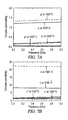
- FIG. 7A depicts measured permeability spectra for synthesized tin (Sn) and zinc (Zn) substituted M-type strontium hexaferrite (Sn/Zn-substituted SrM: SrFe 7 Zn 2.5 Sn 2.5 O 19 ).
- FIG. 7B depicts measured permittivity spectra for synthesized tin (Sn) and zinc (Zn) substituted M-type strontium hexaferrite (Sn/Zn-substituted SrM: SrFe 7 Zn 2.5 Sn 2.5 O 19 ).
- FIG. 8 depicts a table summarizing magnetic properties for synthesized tin (Sn) and zinc (Zn) substituted M-type strontium hexaferrite (Sn/Zn-substituted SrM: SrFe 7 Zn 2.5 Sn 2.5 O 19 ).
- FIG. 9 depicts an exemplary embodiment of a wireless communication apparatus.
- FIG. 10 depicts an exemplary embodiment of a chip antenna system for a wireless communication apparatus, such as is depicted in FIG. 9 .
- FIG. 11A depicts a top view of the antenna system depicted by FIG. 10 after a coaxial cable has been attached to components of the antenna system.
- FIG. 11B depicts an enlarged view of an end of the coaxial cable depicted in FIG. 11A .
- FIG. 11C depicts a cross-sectional view of the chip antenna system of FIG. 10 .
- FIGS. 12A and 12B are flowcharts illustrating exemplary processes for forming an antenna system having a synthesized tin (Sn) and zinc (Zn) substituted M-type strontium hexaferrite (Sn/Zn-substituted SrM: SrFe 7 Zn 2.5 Sn 2.5 O 19 ) antenna.
- FIG. 13 depicts measured voltage standing wave ratio (VSWR) of a fabricated antenna depicted by FIG. 10 .
- FIG. 14 depicts measured average and peak gain of a fabricated antenna depicted by FIG. 10 .
- FIG. 15 depicts an exemplary embodiment of a chip antenna system for a wireless communication apparatus, such as is depicted in FIG. 9 .
- FIG. 16 depicts measured voltage standing wave ratio (VSWR) of a fabricated antenna depicted by FIG. 15 .
- FIG. 17 depicts measured average and peak gain of a fabricated antenna depicted by FIG. 15 .
- FIG. 18 depicts an exemplary embodiment of a chip antenna system for a wireless communication apparatus, such as is depicted in FIG. 9 .
- FIG. 19 depicts measured voltage standing wave ratio (VSWR) of a fabricated antenna depicted by FIG. 18 .
- FIG. 20 depicts measured average and peak gain of a fabricated antenna depicted by FIG. 18 .
- FIG. 21 depicts a table summarizing antenna dimensions and measured performance of fabricated antennas depicted by FIGS. 10, 15, and 18 .
- an antenna is fabricated using an M-type hexaferrite, such as a tin (Sn) and zinc (Zn) substituted M-type strontium hexaferrite (Sn/Zn-substituted SrM: SrFe 12 ⁇ 2x Zn x Sn x O 19 ), thereby enabling antenna miniaturization, broad bandwidth, and high gain.
- M-type hexaferrite such as a tin (Sn) and zinc (Zn) substituted M-type strontium hexaferrite (Sn/Zn-substituted SrM: SrFe 12 ⁇ 2x Zn x Sn x O 19 )
- SrFe 12 ⁇ 2x Zn x Sn x O 19 the value of “x” in the compound SrFe 12 ⁇ 2x Zn x Sn x O 19 is between 2 and 5, but other values of “x” are possible in other embodiments.
- M-type strontium hexaferrite SrM: SrFe 12 O 19
- Sn tin
- Zn zinc
- Such fabricated hexaferrite chip antennas have broadband characteristics and show good radiation performance at various frequencies, including in the GHz frequency range.
- a Sol-gel process is employed to synthesize Sn/Zn-substituted SrM ferrite.
- the price of substitution elements of Sn and Zn is less expensive than cobalt (Co) in the Z-type hexaferrite (Ba 3 Co 2 Fe 24 O 41 ), and the use of Sn/Zn-substituted SrM ferrite is more cost-effective than the Z-type hexaferrite.
- iron cations (Fe 3+ ) occupy five different crystallographic sites in pure strontium (barium) hexaferrite.
- Fe 3+ at the 2b site has the highest magneto crystallineanisotropy, thereby leading to hard magnetic property.
- Magnetic spin directions of Fe 3+ cations at 4f sites are downward opposing the directions of other sites.
- the magnetization per unit cell is about 40 Bohr magnetons ( ⁇ B ).
- part of Fe 3+ cations at 4f and 2b are substituted by non-magnetic Sn and Zn cations. The substitutions cancel spin-down of Fe 3+ cations at 4f sites, resulting in an increase in the saturation magnetization.
- the substitution for 2b sites leads to low magnetocrystalline anisotropy, therefore, becoming soft.
- stoichimetric amounts of raw chemicals (SrCl 2 ⁇ 6 H 2 O, FeCl 3 ⁇ 6 H 2 O, SnCl 4 ⁇ xH 2 O, and ZnCl 2 ) are dissolved in Ethylene glycol with about 12 hours (h) of magnetic stirring.
- the dissolved solution is refluxed at about 150° C. for about 2 hours in N 2 .
- the refluxed solution is evaporated on a hot plate at about 200° C. until complete evaporation.
- the evaporated powder is then collected and grinded, as shown by block 14 .
- the powder is then heated at about 550° C.
- FIG. 4 shows magnetic properties of pure SrM and Sn/Zn-substituted SrM (SSZM: SrFe 7 Sn 2.5 Zn 2.5 O 19 ) heat-treated at various temperatures.
- Coercivity (H c ) otherwise magnetic hardness, decreases with substituting Sn and Zn for Fe in M-type hexaferrite, while maintaining higher saturation magnetization ( ⁇ s ) than the pure SrM. This is because the down-spin of the 4f site and magnetic anisotropy of the 2b site are occupied by Sn and Zn cations. Accordingly, the coercivity for SSZM dramatically decreases to about 34 Oe from about 1100 Oe of the pure SrM. It is noted that SSZN becomes soft. Therefore, higher permeability than that of magnetically hard pure SrM is expected, which is desired for high frequency (e.g., GHz) antenna applications.
- H c Coercivity
- FIG. 5 shows magnetic hysteresis loops of SSZM powder heat-treated at three different temperatures.
- the lowest coercivity of about 33.89 Oe is obtained for about 1500° C. (5 hour) sample, while the 1450° C. (5 hour) sample shows the highest magnetization of about 68.72 emu/g.
- High permeability can be achieved with high saturation magnetization and low coercivity. Therefore, the 1450° C. (10 hour) sample is chosen for antenna fabrication in one exemplary embodiment, though other samples may chosen for other embodiments.
- Magnetic properties of SSZN are summarized in FIG. 8 .
- the following numerical analysis of the magnetization (M) curve was used to estimate the magnetic anisotropy field (H ⁇ ) of SSZM powder.
- M M s ⁇ ( 1 - H a 2 15 ⁇ ⁇ H 2 ) + ⁇ p ⁇ H ( 1 )
- H a 2 ⁇ ⁇ K 1
- M s is the saturation magnetization
- H a is the magnetic anisotropy field
- X p the high field differential susceptibility
- H is the applied field reduced by the demagnetization field
- K 1 is the anisotropy constant.
- the H a of about 4.75 kOe was obtained for the SSZM (heat-treated at about 1450° C. for about 10 h) sample by fitting the hysteresis loop to Eq. (1).
- This magnetic anisotropy field results in ferromagnetic resonance (FMR) frequency of about 13.2 GHz according to Eq. (3).
- FMR ferromagnetic resonance
- f resonance ⁇ ( H 0 +H a )
- f r (2.8 MHz/Oe) ⁇ ( H 0 +H a ) (3)
- H 0 is the applied bias field
- H a is the anisotropy field
- ⁇ is the gyromagnetic ratio.
- FIG. 6 shows the anisotropy dependence of the ferromagnetic resonance frequency.
- the star mark in FIG. 6 represents that the SSZM can be applicable up to about 13.2 GHz.
- FIG. 7A and FIG. 7B represent complex permeability and permittivity, respectively, of SSZM (1450° C. for 10 h) sample.
- Magnetic and dielectric loss tangents can be reduced with employing sintering agent such as Bi 2 O 3 , etc.
- FIG. 9 depicts an exemplary embodiment of a wireless communication device 25 , such as a cellular telephone, having a transceiver 29 that is coupled to an antenna 33 .
- the transceiver 29 is configured for communication in the GHz frequency range, and desirably for such GHz applications, the FMR frequency of ferrite substrate of the antenna 33 is higher than the resonant frequency of the antenna 33 .
- other frequencies are possible in other embodiments.
- FIG. 10 depicts an antenna system 52 having a chip antenna 33 , such as is depicted by FIG. 9 .
- the antenna system 52 has a substrate 55 , which is composed of copper clad laminate (CCL) FR4, though other types of substrate materials may be used in other embodiments.
- a conductive layer 56 As shown by FIG. 10 , formed on a portion of the substrate 55 is a conductive layer 56 , which is coupled to ground (GND) of the device 25 in which the antenna system 52 is used.
- the antenna 33 is also formed on the substrate 55 , as shown by FIG. 10 .
- a radiator 59 (forming a flat conductive trace) is formed on the ferrite substrate of antenna 33 and a portion of the substrate 55 .
- the conductive layer 56 and the radiator 59 are both composed of copper, but other conductive materials may be used in other embodiments.
- the radiator 59 is conductively coupled to the transceiver 29 ( FIG. 10 ).
- the radiator 59 may be coupled to a coaxial cable (not shown in FIG. 10 ) that extends to the transceiver 29 .
- the antenna 33 is composed of tin (Sn) and zinc (Zn) substituted M-type strontium hexaferrite (Sn/Zn-substituted SrM: SrFe 12 ⁇ 2x Zn x Sn x O 19 ), where x has a value between 2 and 5, though other values of x may be used in other embodiments.
- the chip antenna 33 has a length of 9.5 millimeters (mm), a width of 4.5 mm, and a thickness of 1.5 mm, although other dimensions are possible in other embodiments. With the dimensions shown, the chip antenna 33 is suitable for use as a Bluetooth 1 (BT1) antenna.
- FIGS. 11A-C show the antenna system 52 of FIG. 10 after a coaxial cable 63 has been coupled to the chip antenna 33 to provide a conductive path between the antenna radiator 59 and another component, such as transceiver 29 ( FIG. 9 ).
- the coaxial cable 63 has an outer conductor 66 that is coupled (e.g., soldered) to the conductive layer 56 .
- an insulator 68 that surrounds an inner core 69 of conductive material. This inner core 69 is soldered to the radiator 59 at a soldering junction 72 .
- Various other configurations of the antenna system 52 with the antenna 33 are possible in other embodiments.
- FIG. 12A An exemplary process for fabricating the exemplary chip antenna 33 and the system 52 shown by FIG. 10 will be described below with reference to FIGS. 12A and 12B .
- a tin (Sn) and zinc (Zn) substituted M-type strontium hexaferrite antenna substrate is formed, as shown by block 80 of FIG. 12A .
- An exemplary process of performing block 80 is shown by FIG. 12B .
- tin (Sn) and zinc (Zn) substituted M-type strontium hexaferrite powder is formed according to the process depicted by FIG. 2 .
- a ferrite substrate of the antenna 33 is formed by press at about 2750 kgf/cm 2 , as shown by block 85 , and then is sintered at about 1300° C. for about 4 hours, as shown by block 86 .
- an FR4 system board e.g., substrate 55
- radiator 59 formed via conventional microfabrication techniques, such as patterning and etching, as shown by block 91 .
- chip antenna 33 is connected to a coaxial cable 63 , as shown by block 92 .
- the outer conductor 66 of the coaxial cable 63 is soldered to the conductive layer 56
- the inner core 69 of the coaxial cable 63 is soldered to the radiator 59 .
- FIG. 13 presents measured voltage standing wave ratio (VSWR) of the antenna system 52 with the chip antenna 33 of FIG. 10 , which is dimensioned for use as a BT1 antenna.
- the hexaferrite chip antenna shows broadband characteristics, which ensures robust operation of a mobile without a matching network.
- FIG. 14 presents measured antenna gain.
- the maximum 3D peak gain of about ⁇ 0.52 dBi was obtained at about 2.36 GHz.
- the 3D peak and average gains were about ⁇ 1.12 dBi and ⁇ 4.02 dBi, respectively. It is evident that the hexaferrite chip antenna provides a high performance and uniform radiation pattern over the wide frequency band.
- FIG. 15 depicts another embodiment of an antenna system 52 that is configured similar to the one shown by FIG. 10 except that it is dimensioned for use as Bluetooth 2 (BT2) antenna.
- Measured VSWR (voltage standing wave ratio) of the BT2 antenna shown by FIG. 15 is presented in FIG. 16 .
- FIG. 17 shows measured antenna gain for the BT2 antenna shown by FIG. 15 .
- the maximum 3D peak gain of about 2.36 dBi was obtained at about 2.36 GHz.
- the 3D peak and average gains were about 0.71 dBi and ⁇ 2.49 dBi, respectively.
- FIG. 18 depicts another embodiment of an antenna system 52 that is configured similar to the one shown by FIG. 10 except that it is dimensioned for use as an ultra-wideband (UWB) antenna.
- FIG. 19 represents measured VSWR (voltage standing wave ratio) of the UWB antenna shown by FIG. 18 .
- FIG. 20 shows antenna gain for the antenna shown by FIG. 18 in the frequency range of about 3 GHz to 6 GHz.
- the maximum 3D peak and average gains were about 3.89 dBi at 3.2 GHz and ⁇ 1.55 dBi at 3.6 GHz, respectively.
- FIGS. 10, 15, and 18 The dimensions and measured performance of the fabricated hexaferrite chip antennas (BT1, BT2, and UWB) shown by FIGS. 10, 15, and 18 are summarized in FIG. 21 . Yet other dimensions are possible in other embodiments.
Landscapes
- Engineering & Computer Science (AREA)
- Chemical & Material Sciences (AREA)
- Microelectronics & Electronic Packaging (AREA)
- Crystallography & Structural Chemistry (AREA)
- Dispersion Chemistry (AREA)
- Power Engineering (AREA)
- Details Of Aerials (AREA)
- Soft Magnetic Materials (AREA)
Priority Applications (1)
| Application Number | Priority Date | Filing Date | Title |
|---|---|---|---|
| US13/885,374 US9397391B2 (en) | 2010-11-15 | 2011-11-15 | M-type hexaferrite antennas for use in wireless communication devices |
Applications Claiming Priority (3)
| Application Number | Priority Date | Filing Date | Title |
|---|---|---|---|
| US41386610P | 2010-11-15 | 2010-11-15 | |
| US13/885,374 US9397391B2 (en) | 2010-11-15 | 2011-11-15 | M-type hexaferrite antennas for use in wireless communication devices |
| PCT/US2011/060851 WO2012068158A1 (en) | 2010-11-15 | 2011-11-15 | M-type hexaferrite antennas for use in wireless communication devices |
Publications (2)
| Publication Number | Publication Date |
|---|---|
| US20130342414A1 US20130342414A1 (en) | 2013-12-26 |
| US9397391B2 true US9397391B2 (en) | 2016-07-19 |
Family
ID=46084378
Family Applications (1)
| Application Number | Title | Priority Date | Filing Date |
|---|---|---|---|
| US13/885,374 Active 2032-11-10 US9397391B2 (en) | 2010-11-15 | 2011-11-15 | M-type hexaferrite antennas for use in wireless communication devices |
Country Status (5)
| Country | Link |
|---|---|
| US (1) | US9397391B2 (zh) |
| EP (1) | EP2640527A4 (zh) |
| KR (1) | KR101845114B1 (zh) |
| CN (1) | CN103209773B (zh) |
| WO (1) | WO2012068158A1 (zh) |
Families Citing this family (14)
| Publication number | Priority date | Publication date | Assignee | Title |
|---|---|---|---|---|
| US9397391B2 (en) | 2010-11-15 | 2016-07-19 | The Board Of Trustees Of The University Of Alabama | M-type hexaferrite antennas for use in wireless communication devices |
| CN106573848B (zh) | 2014-07-31 | 2020-08-28 | 罗杰斯公司 | 用于超高频天线的Co2Z型铁氧体复合材料 |
| JP6722684B2 (ja) | 2015-01-30 | 2020-07-15 | ロジャーズ コーポレーション | 極超短波用MOドープCo2Z型フェライト複合材料 |
| US10019005B2 (en) | 2015-10-06 | 2018-07-10 | Northrop Grumman Systems Corporation | Autonomous vehicle control system |
| KR102396967B1 (ko) | 2018-02-23 | 2022-05-13 | 로저스코포레이션 | 폴리테트라플루오로에틸렌 헥사페라이트 복합재 |
| DE112019001920T5 (de) | 2018-04-12 | 2020-12-24 | Rogers Corporation | Texturierte planare hexagonale ferrite vom m-typ und verfahren zu deren verwendung |
| CN108899650A (zh) * | 2018-07-09 | 2018-11-27 | 中国计量大学 | 一种可调多频带天线 |
| US11679991B2 (en) | 2019-07-30 | 2023-06-20 | Rogers Corporation | Multiphase ferrites and composites comprising the same |
| KR102268383B1 (ko) | 2019-08-02 | 2021-06-23 | 삼성전기주식회사 | 칩 안테나 |
| CN114206804B (zh) | 2019-08-05 | 2023-06-16 | 罗杰斯公司 | 钌掺杂的z型六方铁氧体 |
| CN110526617B (zh) * | 2019-09-02 | 2022-01-25 | 深圳市信维通信股份有限公司 | 一种天线基板材料 |
| TW202116700A (zh) | 2019-09-24 | 2021-05-01 | 美商羅傑斯公司 | 鉍釕m型六方晶系鐵氧體、包含彼之組合物及複合物、及製造方法 |
| US11783975B2 (en) | 2019-10-17 | 2023-10-10 | Rogers Corporation | Nanocrystalline cobalt doped nickel ferrite particles, method of manufacture, and uses thereof |
| CN115136261A (zh) | 2020-02-21 | 2022-09-30 | 罗杰斯公司 | 具有纳米晶结构的z型六方铁氧体 |
Citations (13)
| Publication number | Priority date | Publication date | Assignee | Title |
|---|---|---|---|---|
| US20020005808A1 (en) * | 2000-03-09 | 2002-01-17 | Hiroki Ito | Antenna apparatus and portable communication appaaratus |
| JP2004339047A (ja) | 2003-04-21 | 2004-12-02 | Murata Mfg Co Ltd | 非可逆回路素子用フェライト磁器組成物、非可逆回路素子、及び無線装置 |
| US20050282043A1 (en) | 2004-06-21 | 2005-12-22 | Fuji Photo Film Co., Ltd. | Hexagonal ferrite magnetic powder, process for producing the same, and magnetic recording medium |
| JP2006066497A (ja) | 2004-08-25 | 2006-03-09 | Murata Mfg Co Ltd | フェライト材料、非可逆回路素子、及び無線装置 |
| EP1798210A1 (en) | 2004-12-17 | 2007-06-20 | Hitachi Metals, Ltd. | Hexagonal ferrite, and antenna and communication equipment using the same |
| US20080055178A1 (en) | 2006-09-04 | 2008-03-06 | Samsung Electro-Mechanics Co., Ltd. | Broad band antenna |
| US7482977B2 (en) * | 2004-03-26 | 2009-01-27 | Sony Corporation | Antenna apparatus |
| US7482997B2 (en) * | 2004-11-25 | 2009-01-27 | Electronics And Telecommunications Research Institute | Voltage/current driven active matrix organic electroluminescent pixel circuit and display device |
| US20100173101A1 (en) | 2006-08-11 | 2010-07-08 | Northeastern University | Method of manufacturing thick-film, low microwave loss, self-biased barium-hexaferrite having perpendicular magnetic anisotropy |
| CN101807746A (zh) | 2010-03-26 | 2010-08-18 | 西南交通大学 | 基于z型六角铁氧体的射频识别天线 |
| WO2011014001A2 (en) | 2009-07-28 | 2011-02-03 | Samsung Electronics Co., Ltd. | Y-type hexagonal ferrite, fabrication method thereof, and antenna apparatus using the same |
| US20130342414A1 (en) | 2010-11-15 | 2013-12-26 | Yang-Ki Hong | Magnetic exchange coupled core-shell nanomagnets |
| WO2014085659A1 (en) | 2012-11-28 | 2014-06-05 | The Board Of Trustees Of The University Of Alabama For And On Behalf Of The University Of Alabama | Dual-polarized magnetic antennas |
Family Cites Families (3)
| Publication number | Priority date | Publication date | Assignee | Title |
|---|---|---|---|---|
| JP2897871B2 (ja) * | 1995-08-11 | 1999-05-31 | ティーディーケイ株式会社 | 磁石粉末、焼結磁石、ボンディッド磁石および磁気記録媒体 |
| KR100639771B1 (ko) * | 2003-02-25 | 2006-11-01 | 티디케이가부시기가이샤 | 페라이트 자석 분말, 소결 자석, 본드 자석 및 자기 기록매체 |
| JP4183190B2 (ja) * | 2004-07-06 | 2008-11-19 | Tdk株式会社 | 非可逆回路素子 |
-
2011
- 2011-11-15 US US13/885,374 patent/US9397391B2/en active Active
- 2011-11-15 WO PCT/US2011/060851 patent/WO2012068158A1/en active Application Filing
- 2011-11-15 KR KR1020137015070A patent/KR101845114B1/ko active IP Right Grant
- 2011-11-15 EP EP11841979.5A patent/EP2640527A4/en not_active Withdrawn
- 2011-11-15 CN CN201180054794.4A patent/CN103209773B/zh not_active Expired - Fee Related
Patent Citations (13)
| Publication number | Priority date | Publication date | Assignee | Title |
|---|---|---|---|---|
| US20020005808A1 (en) * | 2000-03-09 | 2002-01-17 | Hiroki Ito | Antenna apparatus and portable communication appaaratus |
| JP2004339047A (ja) | 2003-04-21 | 2004-12-02 | Murata Mfg Co Ltd | 非可逆回路素子用フェライト磁器組成物、非可逆回路素子、及び無線装置 |
| US7482977B2 (en) * | 2004-03-26 | 2009-01-27 | Sony Corporation | Antenna apparatus |
| US20050282043A1 (en) | 2004-06-21 | 2005-12-22 | Fuji Photo Film Co., Ltd. | Hexagonal ferrite magnetic powder, process for producing the same, and magnetic recording medium |
| JP2006066497A (ja) | 2004-08-25 | 2006-03-09 | Murata Mfg Co Ltd | フェライト材料、非可逆回路素子、及び無線装置 |
| US7482997B2 (en) * | 2004-11-25 | 2009-01-27 | Electronics And Telecommunications Research Institute | Voltage/current driven active matrix organic electroluminescent pixel circuit and display device |
| EP1798210A1 (en) | 2004-12-17 | 2007-06-20 | Hitachi Metals, Ltd. | Hexagonal ferrite, and antenna and communication equipment using the same |
| US20100173101A1 (en) | 2006-08-11 | 2010-07-08 | Northeastern University | Method of manufacturing thick-film, low microwave loss, self-biased barium-hexaferrite having perpendicular magnetic anisotropy |
| US20080055178A1 (en) | 2006-09-04 | 2008-03-06 | Samsung Electro-Mechanics Co., Ltd. | Broad band antenna |
| WO2011014001A2 (en) | 2009-07-28 | 2011-02-03 | Samsung Electronics Co., Ltd. | Y-type hexagonal ferrite, fabrication method thereof, and antenna apparatus using the same |
| CN101807746A (zh) | 2010-03-26 | 2010-08-18 | 西南交通大学 | 基于z型六角铁氧体的射频识别天线 |
| US20130342414A1 (en) | 2010-11-15 | 2013-12-26 | Yang-Ki Hong | Magnetic exchange coupled core-shell nanomagnets |
| WO2014085659A1 (en) | 2012-11-28 | 2014-06-05 | The Board Of Trustees Of The University Of Alabama For And On Behalf Of The University Of Alabama | Dual-polarized magnetic antennas |
Non-Patent Citations (5)
| Title |
|---|
| European Patent Office, European Search Report for Application No. 11841979.5-1556 / 2640527 PCT/US2011060851, dated Feb. 10, 2016. |
| Fang, H.C., et al., "Low temperature characterization of nano-sized BaFe12-2xZnxSnxO19 particles",Journal of Magnetism and Magnetic Materials, vol. 191, No. 3 (Jan. 15, 1999), pp. 277-281. |
| Ghasemi, Ali, et al., "The role of cations distribution on magnetic and reflection loss properties of ferrimagnetic SrFe12-x(Sn0.5Zn0.5)xO19", Journal of Applied Physics, vol. 107, No. 9 (Apr. 27, 2010). |
| Harris, et al., "Recent Advances in Processing and Applications of Microwave Ferrites"; J. Magnestism and Magnetic Mat'ls; Jan. 2009; vol. 321; pp. 2035-2047. |
| Iijima, et al., "Millimeter Wave Absorber using M-type Hexagonal Ferrite" IEEE Int. Symposium on Electromag Compat; Aug. 6, 2002; vol. 2; pp. 547-549. On-line download from: http://ieeexplore.ieee.org/xpl/freeabs-all.jsp?arnumber=874679 on Mar. 11, 2012, abstract only. |
Also Published As
| Publication number | Publication date |
|---|---|
| CN103209773A (zh) | 2013-07-17 |
| CN103209773B (zh) | 2016-06-08 |
| US20130342414A1 (en) | 2013-12-26 |
| KR101845114B1 (ko) | 2018-04-04 |
| KR20130140779A (ko) | 2013-12-24 |
| EP2640527A1 (en) | 2013-09-25 |
| EP2640527A4 (en) | 2016-03-09 |
| WO2012068158A1 (en) | 2012-05-24 |
Similar Documents
| Publication | Publication Date | Title |
|---|---|---|
| US9397391B2 (en) | M-type hexaferrite antennas for use in wireless communication devices | |
| Stergiou et al. | Y-type hexagonal ferrites for microwave absorber and antenna applications | |
| JP6722684B2 (ja) | 極超短波用MOドープCo2Z型フェライト複合材料 | |
| Li et al. | Emerging magnetodielectric materials for 5G communications: 18H hexaferrites | |
| Meena et al. | Complex permittivity, permeability and microwave absorbing properties of (Mn2− xZnx) U-type hexaferrite | |
| JP6637959B2 (ja) | 極超短波アンテナの使用のためのCo2Z−型のフェライト複合材料 | |
| Gan et al. | Low loss, enhanced magneto-dielectric properties of Bi2O3 doped Mg-Cd ferrites for high frequency antennas | |
| Gan et al. | Equivalent permeability and permittivity of Sm substituted Mg–Cd ferrites for high-frequency applications | |
| Heo et al. | Synthesis, characterization, and electromagnetic wave absorption properties of Sr3Co2Fe24O41 hexaferrites | |
| Xie et al. | Co-substituted LiZnTiBi ferrite with equivalent permeability and permittivity for high-frequency miniaturized antenna application | |
| Asif et al. | Synthesis and characterization of Tb doped Ni–Zn nano ferrites as substrate material for dual band MIMO antenna | |
| Adersh et al. | MgFe1. 98O4–BaFe12O19 magneto-dielectric composites based ferrite resonator antenna for super-high frequency applications | |
| Vinaykumar et al. | Low-temperature sintering of SrCo1. 5Ti1. 5Fe9O19 ferrite and its characterization for X-band antenna application | |
| Gan et al. | Ga ions-tailored magnetic-dielectric properties of Mg–Cd composites for high-frequency, miniature and wideband antennas | |
| Vinaykumar et al. | Characterizations of low-temperature sintered BaCo1. 3Ti1. 3Fe9. 4O19 M-type ferrite for high-frequency antenna application | |
| JP6242568B2 (ja) | 高周波用圧粉体、及びそれを用いた電子部品 | |
| Lee et al. | M-type hexaferrite for gigahertz chip antenna applications | |
| JP6659264B2 (ja) | 組成物、rf装置、修飾ニッケル亜鉛フェライト組成物、およびニッケル亜鉛フェライト材料を微調整する方法 | |
| US11705637B2 (en) | Magnetodielectric metamaterials and articles including magnetodielectric metamaterials | |
| Fujii et al. | Co2-Y ferrite modified by CuO addition applied to a terrestrial broadcasting antenna | |
| Guo et al. | Microstructures and High Frequency Properties of ${\hbox {Sm}}^{3+} $ Doped ${\hbox {Co}} _2 {\hbox {Z}} $-Type Hexagonal Ferrites as Anti-EMI Magnetic Bead Materials | |
| Ikhsan et al. | Magneto-dielectric properties of Ni0. 25Cu0. 25Zn0. 50Fe2O4–BaTiO3 and its application as substrate of microstrip patch antennas | |
| Prasath et al. | Miniaturization of patch antennas using magneto-dielectric materials | |
| Cho et al. | Magnetic properties of Sr substituted Y-type hexaferrite | |
| US20220348479A1 (en) | Nickel zinc copper ferrite for vuhf antenna application |
Legal Events
| Date | Code | Title | Description |
|---|---|---|---|
| AS | Assignment |
Owner name: THE BOARD OF TRUSTEES OF THE UNIVERSITY OF ALABAMA Free format text: ASSIGNMENT OF ASSIGNORS INTEREST;ASSIGNORS:HONG, YANG-KI;BAE, SEOK;LEE, JAE-JIN;SIGNING DATES FROM 20130628 TO 20130814;REEL/FRAME:031098/0525 |
|
| STCF | Information on status: patent grant |
Free format text: PATENTED CASE |
|
| MAFP | Maintenance fee payment |
Free format text: PAYMENT OF MAINTENANCE FEE, 4TH YEAR, MICRO ENTITY (ORIGINAL EVENT CODE: M3551); ENTITY STATUS OF PATENT OWNER: MICROENTITY Year of fee payment: 4 |
|
| MAFP | Maintenance fee payment |
Free format text: PAYMENT OF MAINTENANCE FEE, 8TH YEAR, MICRO ENTITY (ORIGINAL EVENT CODE: M3552); ENTITY STATUS OF PATENT OWNER: MICROENTITY Year of fee payment: 8 |