US9333992B2 - Upper slewing body for use in construction machine - Google Patents
Upper slewing body for use in construction machine Download PDFInfo
- Publication number
- US9333992B2 US9333992B2 US14/801,195 US201514801195A US9333992B2 US 9333992 B2 US9333992 B2 US 9333992B2 US 201514801195 A US201514801195 A US 201514801195A US 9333992 B2 US9333992 B2 US 9333992B2
- Authority
- US
- United States
- Prior art keywords
- cab
- reinforcing member
- pillar
- displacement
- wall
- Prior art date
- Legal status (The legal status is an assumption and is not a legal conclusion. Google has not performed a legal analysis and makes no representation as to the accuracy of the status listed.)
- Active
Links
- 238000010276 construction Methods 0.000 title claims description 19
- 230000003014 reinforcing effect Effects 0.000 claims abstract description 100
- 238000006073 displacement reaction Methods 0.000 claims abstract description 53
- 239000000837 restrainer Substances 0.000 claims abstract description 31
- 230000000149 penetrating effect Effects 0.000 claims abstract description 21
- 230000000630 rising effect Effects 0.000 claims abstract description 18
- 238000007789 sealing Methods 0.000 claims description 24
- 239000013013 elastic material Substances 0.000 claims description 12
- 230000000452 restraining effect Effects 0.000 abstract description 18
- 238000003466 welding Methods 0.000 description 7
- 230000000052 comparative effect Effects 0.000 description 6
- 230000005540 biological transmission Effects 0.000 description 5
- 230000000694 effects Effects 0.000 description 5
- 230000002159 abnormal effect Effects 0.000 description 3
- 230000005489 elastic deformation Effects 0.000 description 3
- 230000002708 enhancing effect Effects 0.000 description 3
- 238000002955 isolation Methods 0.000 description 3
- 230000004048 modification Effects 0.000 description 3
- 238000012986 modification Methods 0.000 description 3
- 230000002787 reinforcement Effects 0.000 description 2
- 125000006850 spacer group Chemical group 0.000 description 2
- 230000006835 compression Effects 0.000 description 1
- 238000007906 compression Methods 0.000 description 1
- 239000006185 dispersion Substances 0.000 description 1
- 238000005516 engineering process Methods 0.000 description 1
- 238000000034 method Methods 0.000 description 1
- 230000002265 prevention Effects 0.000 description 1
Images


Classifications
-
- B—PERFORMING OPERATIONS; TRANSPORTING
- B62—LAND VEHICLES FOR TRAVELLING OTHERWISE THAN ON RAILS
- B62D—MOTOR VEHICLES; TRAILERS
- B62D33/00—Superstructures for load-carrying vehicles
- B62D33/06—Drivers' cabs
- B62D33/0604—Cabs insulated against vibrations or noise, e.g. with elastic suspension
-
- B—PERFORMING OPERATIONS; TRANSPORTING
- B62—LAND VEHICLES FOR TRAVELLING OTHERWISE THAN ON RAILS
- B62D—MOTOR VEHICLES; TRAILERS
- B62D33/00—Superstructures for load-carrying vehicles
- B62D33/06—Drivers' cabs
- B62D33/0617—Drivers' cabs for tractors or off-the-road vehicles
-
- E—FIXED CONSTRUCTIONS
- E02—HYDRAULIC ENGINEERING; FOUNDATIONS; SOIL SHIFTING
- E02F—DREDGING; SOIL-SHIFTING
- E02F9/00—Component parts of dredgers or soil-shifting machines, not restricted to one of the kinds covered by groups E02F3/00 - E02F7/00
- E02F9/08—Superstructures; Supports for superstructures
- E02F9/0808—Improving mounting or assembling, e.g. frame elements, disposition of all the components on the superstructures
-
- E—FIXED CONSTRUCTIONS
- E02—HYDRAULIC ENGINEERING; FOUNDATIONS; SOIL SHIFTING
- E02F—DREDGING; SOIL-SHIFTING
- E02F9/00—Component parts of dredgers or soil-shifting machines, not restricted to one of the kinds covered by groups E02F3/00 - E02F7/00
- E02F9/16—Cabins, platforms, or the like, for drivers
- E02F9/163—Structures to protect drivers, e.g. cabins, doors for cabins; Falling object protection structure [FOPS]; Roll over protection structure [ROPS]
-
- E—FIXED CONSTRUCTIONS
- E02—HYDRAULIC ENGINEERING; FOUNDATIONS; SOIL SHIFTING
- E02F—DREDGING; SOIL-SHIFTING
- E02F9/00—Component parts of dredgers or soil-shifting machines, not restricted to one of the kinds covered by groups E02F3/00 - E02F7/00
- E02F9/16—Cabins, platforms, or the like, for drivers
- E02F9/166—Cabins, platforms, or the like, for drivers movable, tiltable or pivoting, e.g. movable seats, dampening arrangements of cabins
-
- F—MECHANICAL ENGINEERING; LIGHTING; HEATING; WEAPONS; BLASTING
- F16—ENGINEERING ELEMENTS AND UNITS; GENERAL MEASURES FOR PRODUCING AND MAINTAINING EFFECTIVE FUNCTIONING OF MACHINES OR INSTALLATIONS; THERMAL INSULATION IN GENERAL
- F16F—SPRINGS; SHOCK-ABSORBERS; MEANS FOR DAMPING VIBRATION
- F16F15/00—Suppression of vibrations in systems; Means or arrangements for avoiding or reducing out-of-balance forces, e.g. due to motion
- F16F15/10—Suppression of vibrations in rotating systems by making use of members moving with the system
Definitions
- the present invention relates to an upper slewing body for use in a construction machine such as an excavator, the upper stewing body including a cab in which an operator rides and an upper frame supporting the cab.
- An ordinary excavator includes a crawler type lower travelling body, an upper slewing body mounted on the lower travelling body so as to be slewable, and a working attachment attached to the upper slewing body, the working attachment including a boom.
- the upper slewing body includes a cab in which an operator rides and an upper frame supporting the cab, the cab including a bottom frame forming the bottom of the cab and a plurality of pillars joined to the bottom frame.
- an upper slewing body including an antivibration mount disposed between the cab and the upper frame.
- the antivibration mount is, as disclosed in Japanese Unexamined Patent Publication No. 2001-193103 and Japanese Unexamined Patent Publication No. 2009-133119, made of an elastic material such as vibration isolation rubber, and elastically deformed to permit the cab to make a relative displacement with respect to the upper frame vertically and horizontally to thereby suppress transmission of a vibration from the upper frame to the cab.
- Japanese Unexamined Patent Publication No. 2001-193103 discloses a means to restrain a displacement of the cab, the means including a bolt passing through the upper frame and the cab, and a nut attached to an upper end of the bolt, the nut being operable to come into contact with an upper surface of a bottom frame of the cab to thereby restrain the displacement of the cab.
- Japanese Unexamined Patent Publication No. 2009-133119 discloses a construction machine including a plate with a hole disposed on an upper frame and projecting upward, and a shaft horizontally projecting from a cab to pass through the hole of the plate with a clearance corresponding to a permissible deformation amount of an antivibration mount.
- the shaft comes into contact with the plate when an upward displacement, i.e., rising, of the cab with respect to the upper frame reaches the permissible deformation amount, thereby preventing the cab from excessive rising.
- the object of the present invention is to provide an upper slewing body for use in a construction machine, the upper slewing body including an upper frame and a cab, and being capable of restraining the cab from excessively rising away from the upper frame and preventing an outer pillar included in the cab from falling down.
- an upper slewing body for use in a construction machine, configured to be mounted on a lower travelling body of the construction machine so as to be slewable, the upper slewing body comprising: an upper frame including a left side portion and a right side portion; a cab mounted on one of the left side portion and the right side portion, the cab including a bottom frame constituting a bottom wall of the cab, a plurality of pillars each having a lower end joined to an upper surface of the bottom frame to thereby allow the pillar to stand on a periphery of the cab, and an entrance opening on an outer side of the upper frame, the plurality of pillars including an outer pillar located on a side where the entrance opening exists; an antivibration mount for suppressing a vibration of the cab; a displacement restrainer for limiting a displacement of the cab relative to the upper frame in a direction of rising away from the upper frame to a specific amount or less; and a reinforcing member attached to the lower end
- the displacement restrainer includes a penetrating member vertically penetrating the reinforcing member and the bottom frame and being secured to the upper frame.
- the displacement restrainer and the reinforcing member include respective load transmitting surfaces which are vertically opposed to each other so as to transmit a load to each other at a position above the joint between the bottom frame and the outer pillar when the cab is displaced in the rising direction by the specific amount or more.
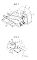
- FIG. 1 is a perspective view of an upper frame and a cab of an upper slewing body according to an embodiment of the present invention.
- FIG. 2 is an enlarged view of a portion enclosed by the circle II in FIG. 1 .
- FIG. 3 is a plan view of the portion shown in FIG. 2 .
- FIG. 4 is an enlarged cross-sectional view taken along the line IV-IV in FIG. 3 .
- FIG. 5 is an enlarged cross-sectional view taken along the line V-V in FIG. 3 .
- FIG. 6 is a perspective view of a reinforcing member included in the upper slewing body.
- FIG. 7 is a perspective view of a modified reinforcing member.
- FIGS. 8A, 8B, and 8C are respective plan views showing modified dispositions of the reinforcing member.
- FIG. 9 is a perspective view of an upper frame and a cab of an upper slewing body according to a comparative example to the embodiment of the present invention (prior art).
- FIG. 10 is a sectional view showing a structure for supporting the cab according to the comparative example (prior art).
- FIGS. 9 and 10 Prior to describing the embodiment of the present invention, will be described an upper slewing body according to a comparative example (prior art) shown in FIGS. 9 and 10 in order to clarify the feature of the embodiment of the present invention.
- the upper slewing body shown in FIG. 9 includes an upper frame 1 , a cab 2 , and a plurality of antivibration mounts 4 .
- the upper frame 1 includes a left side deck 3 L forming a left side portion thereof and a right side deck 3 R forming a right side portion thereof.
- the cab 2 is mounted on one of the left side portion and the right side portion.
- “forward-backward direction” and “left-right direction” of the upper stewing body according to the comparative example and an upper slewing body according to the later described embodiment will be specified based on the assumption that the cab is mounted on the left side portion of the upper frame as shown in FIG. 9 (on the left side deck in FIG. 9 ).
- the cab 2 is mounted on a front portion of the left side deck 3 L.
- the cab 2 includes an entrance 2 a opening on a laterally outer side thereof.
- the plurality of antivibration mounts 4 are disposed between four corners of the bottom of the cab 2 and the corresponding portions of the upper frame 1 located thereunder, respectively, thus supporting the cab 2 .
- Each of the antivibration mounts 4 is made of an elastic material such as vibration isolation rubber, being elastically deformable to permit the cab 2 to make a displacement with respect to the upper frame 1 vertically and horizontally to thereby suppress transmission of a vibration from the upper frame 1 to the cab 2 .
- the antivibration mounts 4 exert a resistance force against a load acting on the cab 2 in a direction of raising the cab 2 away from the left side deck 3 L of the upper frame 1 , the resistance force being exerted by extension of the elastic materials constituting the antivibration mounts 4 in the rising direction.
- a displacement of the cab 2 is so great as to exceed a normal stroke of the antivibration mounts 4 upon overturning of the machine, the elastic materials of the antivibration mounts 4 are liable to reach its elastic limit to be broken; hence, in order to protect the antivibration mounts 4 , there is provided a displacement restrainer for restraining a displacement of the cab 2 .
- the displacement restrainer includes a bolt 6 and a nut 7 shown in FIG. 10 .
- the bolt 6 penetrates the left side deck 3 L of the upper frame 1 and a bottom frame 5 defining a periphery of the bottom of the cab 2 , the nut 7 being attached to an upper end of the bolt 6 .
- the nut 7 comes into contact with an upper surface of the bottom frame 5 when the cab 2 is displaced in the rising direction by a specific amount or more, thereby restraining the cab 2 from further displacement.
- the bottom of the cab is constituted by the bottom frame 5 and a floor plate 9 shown in FIG. 10 .
- There is given a clearance CL between a lower surface of the nut 7 and the upper surface of the bottom frame 5 the clearance CL corresponding to a permissible elastic deformation amount of the antivibration mounts 4 .
- the cab 2 further includes a plurality of pillars 8 constituting a cab frame which is a main structure of the cab, one of the pillars 8 being shown in FIG. 10 .
- Each of the pillars 8 is in the form of a hollow rectangular column.
- the plurality of pillars 8 are provided, for example, at front and rear portions on the right side, and front, middle, and rear portions on the left side including the entrance 2 a , respectively.
- Each of the pillars 8 has a lower end and is kept standing by joining the lower end to the upper surface of the bottom frame 5 , for example, by welding.
- a pillar on the entrance side i.e., on the outer side, included in the plurality of pillars 8 receives a lateral load, that is, a load in the left-right direction or in the forward-backward direction.
- the structure according to the comparative example cannot exert a resistance force against a lateral load acting on the outer pillar 8 (that is, a load in the left-right direction or in the forward-backward direction), even though being capable of suppressing a displacement of the cab 2 with respect to the upper frame 1 in the rising direction. Therefore, there is a possibility of a large load which acts on the lower end joint where the lower end of the outer pillar 8 is joined with the bottom frame 5 , upon overturning of the machine, which may break the lower end joint. The break in the lower end joint will permit the outer pillar 8 to fall down, thus making the cab 2 be likely to be deformed.
- FIGS. 1 to 8 show a structure of the upper slewing body according to the embodiment of the present invention, the structure being able to overcome the above-described problems of the upper slewing body according to the comparative example.
- the upper slewing body constitutes a part of an excavator which is a construction machine including a crawler-type lower travelling body and a working attachment such as a boom, mounted on the lower travelling body so as to be slewable.
- the working attachment is attached to the upper slewing body.
- the upper slewing body includes an upper frame 11 and a cab 12 shown in FIG. 1 .
- the upper frame 11 includes a left side deck 13 L which is a left side portion thereof and a right side deck 13 R which is a right side portion thereof, the cab 12 mounted on a front portion of the left side deck 13 L.
- the cab 12 includes an entrance 10 opening on an outer side thereof.
- the upper slewing body further includes a plurality of antivibration mounts 14 .
- the plurality of antivibration mounts 14 are disposed between four corners of the bottom of the cab 12 and the corresponding portions of the upper frame 11 located thereunder, respectively.
- the cab 12 is mounted on the upper frame 11 via the plurality of antivibration mounts 14 .
- Each of the antivibration mounts 14 is made of an elastic material such as vibration isolation rubber.
- the antivibration mounts 14 support the cab 12 while permitting the cab 12 to be vertically and horizontally displaced within a specific range by elastic deformation of the elastic materials, thereby suppressing transmission of a vibration from the upper frame 11 to the cab 12 .
- the antivibration mounts 14 exert a resistance force against a load on the cab 12 in a direction of raising the cab 4 away from the left side deck 13 L of the upper frame 11 , the resistance force being exerted by extension of the elastic materials constituting the antivibration mounts 14 in the rising direction.
- the upper slewing body further includes a displacement restrainer described below, the displacement restrainer restraining the displacement of the cab 12 to protect the antivibration mounts 14 .
- the cab 12 includes a bottom frame 16 defining a periphery of the bottom thereof, a plurality of pillars constituting a cab frame which is a main structure of the cab 12 , and a floor plate 17 constituting the bottom of the cab 12 in cooperation with the bottom frame 16 .
- the plurality of pillars are provided, for example, at front and rear portions on the right side, and front, middle, and rear portions on the left side where the entrance 10 exists, respectively.
- FIGS. 1 to 6 show a pillar 15 disposed at the left rear portion on a side where the entrance 10 exists, the pillar 15 being one of the plurality of pillars and exemplifying “an outer pillar” of the present invention.
- the upper slewing body according to the present embodiment includes a structure for restraining the pillar 15 from falling down.
- the pillar 15 has a lower end, which is joined to an upper surface of the bottom frame 16 , for example, by welding, to thereby keep the pillar 15 standing.
- the pillar 15 thus, receives a lateral load, i.e., a load in the left-right direction or in the forward-backward direction, upon overturning of the machine.
- the upper slewing body further includes a reinforcing member 18 secured to a right surface of the lower end of the pillar 15 .
- the reinforcing member 18 is in the form of a box including a top wall 18 a , a bottom wall 18 b , a left wall 18 c , a right wall 18 d , a front wall 18 e , and an unillustrated rear wall, these walls defining an internal space.
- the left wall 18 c of the reinforcing member 18 is secured to the pillar 15 while making surface contact with the right surface of the pillar 15 .
- the bottom wall 18 b of the reinforcing member 18 is secured to the bottom frame 16 while making surface contact with the upper surface of the bottom frame 16 .
- a joining method such as welding, bolt fastening or the like.
- the left surface of the reinforcing member 18 has a dimension As with respect to the forward-backward direction, the dimension As being greater than a dimension Bs of the right surface of the pillar 15 in the forward-backward direction, in plan view.
- the reinforcing member 18 thus, has a front end which protrudes beyond a front surface of the pillar 15 .
- this upper slewing body there are provided a plurality of bolt passage holes 19 vertically passing through the bottom wall 18 b and the top wall 18 a of the reinforcing member 18 , the bottom frame 16 , the floor plate 17 , and the left side deck 13 L of the upper frame 11 , respectively, a restraining bolt 20 being inserted into the plurality of bolt passage holes 19 from above as a penetrating member. The restraining bolt 20 thus penetrates the reinforcing member 18 and the bottom frame 16 vertically.
- the restraining bolt 20 has opposite ends, namely, a head 20 a and a lower end 20 b , and at least the lower end 20 b is formed with a male thread.
- a tapped block 21 having a screw hole 21 b as a female thread member.
- the lower end 20 b is screwed into the screw hole 21 b , thereby secured to the upper frame 11 via the tapped block 21 .
- the upper slewing body further includes a washer 22 , and a sealing member 23 made of an elastic material.
- the washer 22 and the sealing member 23 are loosely fit around the restraining bolt 20 in such a manner that the washer 22 is placed above the sealing member 23 between the head 20 a and the top wall 18 a of the reinforcing member 18 .
- the sealing member 23 seals an annular space of the bolt passage hole 19 formed in the top wall 18 a of the reinforcing member 18 by the elastic deformation of the sealing member 23 itself, in the case of such displacement of the cab 12 with respect to the upper frame 11 that deformation of the antivibration mounts 14 is equal to or less than the permissible deformation amount.
- the sealing member 23 is allowed to reach its elastic limit by such displacement that deformation of the antivibration mounts 14 exceeds the permissible deformation amount, thereby making an action of transmitting a load between the washer 22 and the reinforcing member 18 .
- the displacement restrainer of the upper slewing body includes the restraining bolt 20 as the penetrating member and the washer 22 , while the sealing member 23 is interposed between a lower surface of the washer 22 and the top wall 18 a of the reinforcing member 18 , allowing the lower surface of the washer 22 and an upper surface of the top wall 18 a of the reinforcing member 18 to come into contact with the sealing member 23 to sandwich the sealing member 23 therebetween to thereby limit a displacement of the cab 12 in the rising direction to a specific amount or less when the cab 12 is displaced relatively to the upper frame 11 in the rising direction by the specific amount or more.
- the present embodiment further includes a cylindrical spacer 24 .
- the spacer 24 is disposed between an upper surface of the upper frame 11 and the lower surface of the washer 22 , while loosely fitted around the restraining bolt 20 , to thereby define a minimum gap between the upper surface of the upper frame 11 and the lower surface of the washer 22 , i.e., a maximum compression amount of the sealing member 23 .
- the reinforcing member 18 receives a lateral load which acts on the pillar 15 , in particular in the left-right direction, as a result of overturning of the machine including the upper slewing body, and transmits the load to the upper frame 11 via the displacement restrainer. In this manner, the following advantageous effects can be obtained.
- the reinforcing member 18 can strengthen the lower end joint of the pillar 15 by being attached to the lower end, i.e., the basal portion, of the pillar 15 . Specifically, the reinforcing member 18 can disperse a lateral load acting on the pillar 15 to thereby reduce a load acting on the lower end joint of the pillar 15 . Furthermore, the reinforcing member 18 , engaged with the restraining bolt 20 at a position above the lower end joint of the pillar 15 , can transmit the lateral load acting thereon upon overturning of the machine to the restraining bolt 20 secured to the upper frame 11 , at a position above the lower end joint of the pillar 15 . This allows the load acting on the lower end joint to be further reduced. The pillar 15 is, thus, effectively prevented from falling down upon overturning of the machine.
- the reinforcing member 18 includes the top wall 18 a which is a horizontal one formed with the bolt passage hole 19 allowing the restraining bolt 20 to pass therethrough, while the washer 22 is placed around the restraining bolt 20 and each of the upper surface of the top wall 18 a and the lower surface of the washer 22 serves as the load transmitting surface opposed to each other (specifically, each comes into contact with the same sealing member 23 ) so as to transmit a load to each other; this allows the reinforcing member 18 to function as load transmission means in cooperation with the displacement restrainer and, therefore, allows the cab to have a simplified structure, for example, as compared to the case of adding reinforcement to a structural element of the cab such as the bottom frame itself to make it constitute a part of the displacement restrainer.
- the sealing member 23 is disposed between the upper surface of the top wall 18 a serving as the load transmitting surface of the reinforcing member 18 and the lower surface of the washer 22 serving as the load transmitting surface of the displacement restrainer to come into contact with the load transmitting surfaces, having the following functions: a function of sealing the space defined around the restraining bolt 20 passing through the passage holes 19 in a normal state where a relative displacement of the cab 12 with respect to the upper frame 11 is so small that deformation of the antivibration mounts 14 is equal to or less than the permissible deformation amount; and a function of transmitting a load between the load transmitting surfaces in an abnormal state where the above relative displacement is so great that deformation of the antivibration mounts 14 exceeds the permissible deformation amount.
- the sealing member 23 can ensure air tightness in the cab 12 by preventing flow of air between the inside and the outside of the cab 12 through the space around the bolt 20 passing through the passage holes 19 in the normal state, and can reliably performs the function of transmitting a load between the load transmitting surfaces in the abnormal state.
- the reinforcing member 18 is in the form of a box including the top wall 18 a , the bottom wall 18 b , the left wall 18 c , the right wall 18 d , the front wall 18 e , and the rear wall, all of which walls define an internal space, the upper surface of the top wall 18 a serving as the load transmitting surface and the outer surface of the left wall 18 c which is one of the outer surfaces of the reinforcing member 18 coming into surface contact with the right surface of the pillar 15 .
- the pillar 15 attached with the reinforcing member 18 is originally provided with high rigidity which makes the pillar 15 hard to deform upon overturning, and therefore has a structure not likely to release a load and allowing the lower end joint thereof to be easily broken. Accordingly, the attachment of the reinforcing member 18 to the pillar 15 is very effective for preventing the pillar 15 from falling down.
- the reinforcing member 18 disposed with utilization of an existing dead space in the cab 12 , requires neither creating an additional space outside the cab 12 nor changing the arrangement of structural elements disposed outside the cab 12 to create the space, different from the case of disposing the reinforcing member 18 outside the cab 12 . This facilitates layout of the elements around the cab 12 .
- the sealing member 23 is disposed between the lower surface of the washer 22 and the upper surface of top wall 18 a of the reinforcing member 18 to have a function of transmitting a load between those surfaces in the abnormal state
- the present invention also includes an embodiment including a different sealing member having only a sealing function, for example, a sealing member disposed in contact with one or some of the lower surface of the top wall 18 a , and the upper and lower surfaces of the bottom wall 18 b of the reinforcing member 18 .
- the sealing member is allowed to be omitted as appropriate.
- the reinforcing member according to the present invention is not limited to one formed in a box shape such as the reinforcing member 18 .
- the shape of the reinforcing member can be variously modified as long as the reinforcing member can receive a lateral load upon overturning of the machine and constitute a displacement restrainer.
- FIG. 7 shows a reinforcing member 38 as a modification.
- the reinforcing member 38 includes a pair of front and rear plates 38 b , 38 b , and a horizontal wall 38 c disposed between the pair of plates 38 b , 38 b , having an H-shape in a side view.
- Each of the plates 38 b has a substantially right triangle shape with a horizontal base side and a vertical side joinable to the side surface of the pillar 15 .
- the horizontal wall 38 c is formed with a bolt passage hole 19 .
- FIGS. 8A, 8B , and 8 C illustrate respective examples in each of which the reinforcing member 18 is disposed at a different position.
- FIGS. 8A to 8C show, in addition to the pillar 15 (disposed at the left rear portion), a pillar 25 disposed at the left middle portion, a pillar 26 disposed at a left front portion, a pillar 27 disposed at a right rear portion, and a pillar 28 disposed at a right front portion, respectively, and each of the pillars 15 , 25 and 26 out of the above pillars corresponds to the outer pillar.
- the positions illustrated below are applicable not only to the reinforcing member 18 but also to, for example, the reinforcing member 38 . In other words, the specific structure of the reinforcing member does not matter.
- the reinforcing member 18 may be disposed at, other than the position according to the above-described embodiment, i.e., on the right side of the pillar 15 (which is disposed at the left rear portion) shown by the solid line in FIG. 8A , positions shown by the dashed line in FIG. 8A , i.e., on the front side of the pillar 15 or on the rear side of the pillar 15 at the outside of the cab 12 .
- the reinforcing member 18 may be disposed on the left side or on the rear side of the pillar 25 disposed at the left middle portion as shown by the dashed line in FIG. 8B .
- the reinforcing member 18 may be disposed on the right side of the pillar 26 disposed at the left front portion as shown in FIG. 8C .
- the reinforcing member 18 is highly effectively protected against a horizontal load, in particular, components of the horizontal load acting in the forward-backward direction, when disposed on the rear side or the front side of the outer pillar.
- the present invention can include a plurality of reinforcing members attached to respective surfaces of a common pillar, or can include a plurality of reinforcing members attached to respective pillars disposed outside.
- an upper slewing body for use in a construction machine, the upper slewing body including an upper frame and a cab, and being capable of restraining the cab from excessively rising away from the upper frame and preventing an outer pillar included in the cab from falling down.
- the upper slewing body is configured to be mounted on a lower travelling body of the construction machine so as to be slewable, comprising: an upper frame including a left side portion and a right side portion; a cab mounted on one of the left side portion and the right side portion, the cab including a bottom frame constituting a bottom wall of the cab, a plurality of pillars each having a lower end joined to an upper surface of the bottom frame to thereby allow the pillar to stand on a periphery of the cab, and an entrance opening on an outer side of the upper frame, the plurality of pillars including an outer pillar located on a side where the entrance opening exists; an antivibration mount for suppressing a vibration of the cab; a displacement restrainer for limiting a relative displacement of the cab with respect to the upper frame in a direction of rising away from the upper frame to a specific amount or less; and a reinforcing member attached to the lower end of the outer pillar to reinforce a joint between the lower end
- the displacement restrainer includes a penetrating member vertically penetrating the reinforcing member and the bottom frame and being secured to the upper frame.
- the displacement restrainer and the reinforcing member include respective load transmitting surfaces which are vertically opposed to each other so as to transmit a load to each other at a position above the joint between the bottom frame and the outer pillar when the cab is displaced in the rising direction by the specific amount or more.
- the reinforcing member of the upper slewing body, attached to the lower end, i.e., the basal portion, of the outer pillar, can strengthen the lower end joint. Specifically, the reinforcing member can disperse a lateral load acting on the outer pillar, thereby reducing a load acting on the lower end joint of the outer pillar. Furthermore, the reinforcing member, engaged with the penetrating member constituting the displacement restrainer at a position above the lower end joint of the outer pillar, can transmit the lateral load acting on the cab upon overturning of the machine to the penetrating member and further to the upper frame, at a position above the lower end joint of the outer pillar, thereby reducing a load acting on the lower end joint. Thus, the pillar is effectively prevented from falling down upon overturning of the machine.
- the reinforcing member includes a horizontal wall formed with a penetrating-member passage hole allowing the penetrating member to penetrate therethrough;
- the displacement restrainer includes a washer placed around the penetrating member;
- the horizontal wall has an upper surface serving as the load transmitting surface of the reinforcing member;
- the washer has a lower surface serving as the load transmitting surface of the displacement restrainer.
- the upper slewing body further comprises a sealing member made of an elastic material and disposed between the respective load transmitting surfaces of the reinforcing member and the displacement restrainer, the sealing member configured to seal a space defined around the penetrating member penetrating the reinforcing member and the bottom frame when deformation of the antivibration mount is equal to or less than a permissible deformation amount and configured to transmit a load between the load transmitting surfaces when deformation of the antivibration mount exceeds the permissible deformation amount.
- a sealing member made of an elastic material and disposed between the respective load transmitting surfaces of the reinforcing member and the displacement restrainer, the sealing member configured to seal a space defined around the penetrating member penetrating the reinforcing member and the bottom frame when deformation of the antivibration mount is equal to or less than a permissible deformation amount and configured to transmit a load between the load transmitting surfaces when deformation of the antivibration mount exceeds the permissible deformation amount.
- the sealing member can maintain air tightness in the cab by preventing flow of air between the inside and the outside of the cab through the space around the penetrating member passing through the reinforcing member and the bottom frame, and further, when deformation of the antivibration mount exceeds the permissible deformation amount, can function as a member transmitting a load between the load transmitting surfaces.
- the reinforcing member is in the form of a box including a front wall, a rear wall, a left wall, a right wall, a top wall and a bottom wall to define an internal space, the top wall having an upper surface serving as the load transmitting surface of the reinforcing member, and that the reinforcing member is attached to the outer pillar with an outer surface of one of the front wall, the rear wall, the left wall and the right wall, while making surface contact with a side surface of the outer pillar.
- the outer surface of the reinforcing member making surface contact with the outer pillar has a greater dimension in plan view, than a dimension in plan view of the side surface of the outer pillar making surface contact with the outer surface.
- the outer pillar attached with the reinforcing member is disposed at a rear portion of the cab.
- the thus disposed pillar is close to an operator's seat, and is therefore given high rigidity so as not to be likely to deform upon overturning in the perspective of protecting an occupant, thus being not likely to release a load and therefore allowing the lower end joint to be easily broken. Accordingly, the attachment of the reinforcing member to the pillar is especially effective for prevention of the pillar from falling down.
- the reinforcing member is attached to the outer pillar while disposed inside the cab. This makes it possible to utilize an existing dead space in the cab to be utilized, thus eliminating need for creating an additional space outside the cab or for changing the arrangement of structural elements disposed outside the cab to create the space, different from the case of disposing the reinforcing member outside the cab. This facilitates layout of the elements around the cab.
Landscapes
- Engineering & Computer Science (AREA)
- General Engineering & Computer Science (AREA)
- Civil Engineering (AREA)
- Structural Engineering (AREA)
- Mining & Mineral Resources (AREA)
- Mechanical Engineering (AREA)
- Transportation (AREA)
- Chemical & Material Sciences (AREA)
- Combustion & Propulsion (AREA)
- Physics & Mathematics (AREA)
- Acoustics & Sound (AREA)
- Aviation & Aerospace Engineering (AREA)
- Body Structure For Vehicles (AREA)
- Component Parts Of Construction Machinery (AREA)
- Vibration Prevention Devices (AREA)
Applications Claiming Priority (2)
| Application Number | Priority Date | Filing Date | Title |
|---|---|---|---|
| JP2014-157590 | 2014-08-01 | ||
| JP2014157590A JP5979187B2 (ja) | 2014-08-01 | 2014-08-01 | 建設機械のキャブ支持構造 |
Publications (2)
| Publication Number | Publication Date |
|---|---|
| US20160031494A1 US20160031494A1 (en) | 2016-02-04 |
| US9333992B2 true US9333992B2 (en) | 2016-05-10 |
Family
ID=53776349
Family Applications (1)
| Application Number | Title | Priority Date | Filing Date |
|---|---|---|---|
| US14/801,195 Active US9333992B2 (en) | 2014-08-01 | 2015-07-16 | Upper slewing body for use in construction machine |
Country Status (4)
| Country | Link |
|---|---|
| US (1) | US9333992B2 (de) |
| EP (1) | EP2980321B1 (de) |
| JP (1) | JP5979187B2 (de) |
| CN (1) | CN105317068B (de) |
Cited By (3)
| Publication number | Priority date | Publication date | Assignee | Title |
|---|---|---|---|---|
| US9908497B2 (en) * | 2013-10-29 | 2018-03-06 | Caterpillar Sarl | Cab support structure of construction machine |
| US11203853B2 (en) * | 2017-02-28 | 2021-12-21 | Doosan Infracore Co., Ltd. | Cabin assembly for construction equipment |
| US11772716B1 (en) | 2022-03-14 | 2023-10-03 | Deere & Company | Suspension system for an operator station of a work vehicle |
Families Citing this family (11)
| Publication number | Priority date | Publication date | Assignee | Title |
|---|---|---|---|---|
| JP6719822B2 (ja) * | 2016-09-21 | 2020-07-08 | 日本車輌製造株式会社 | 積載物の取付構造 |
| US11203383B2 (en) | 2017-12-21 | 2021-12-21 | Deere & Company | Operator station suspension system |
| US10793204B2 (en) * | 2018-12-03 | 2020-10-06 | Deere & Company | Operator station suspension isolation system |
| US10717475B2 (en) * | 2018-12-03 | 2020-07-21 | Deere & Company | Operator station suspension isolation system |
| JP7195805B2 (ja) | 2018-07-31 | 2022-12-26 | 株式会社小松製作所 | 作業機械 |
| JP7236942B2 (ja) * | 2019-06-19 | 2023-03-10 | 株式会社小松製作所 | 作業車両 |
| JP7567567B2 (ja) * | 2020-09-30 | 2024-10-16 | コベルコ建機株式会社 | 作業機械 |
| US11970228B2 (en) * | 2022-01-26 | 2024-04-30 | Zoomlion Heavy Industry Na, Inc. | Docking station for supporting a remote wireless cab |
| JP7792259B2 (ja) * | 2022-02-01 | 2025-12-25 | 株式会社加藤製作所 | 建設機械のキャブの繋留構造 |
| US20230279880A1 (en) * | 2022-03-04 | 2023-09-07 | Zoomlion Heavy Industry Na, Inc. | Remote-Controlled Wireless Frame |
| JP7810607B2 (ja) * | 2022-05-19 | 2026-02-03 | Toyo Tire株式会社 | 防振装置 |
Citations (40)
| Publication number | Priority date | Publication date | Assignee | Title |
|---|---|---|---|---|
| US3713203A (en) * | 1970-11-05 | 1973-01-30 | Int Harvester Co | Mounting blocks in vehicle frame and method of installation therein |
| US4043585A (en) * | 1975-03-26 | 1977-08-23 | Mitsubishi Jidosha Kogyo Kabushiki Kaisha | Buffer for vehicle |
| US4095839A (en) * | 1976-05-24 | 1978-06-20 | Caterpillar Tractor Co. | Falling object protective structure |
| US4274671A (en) * | 1979-12-12 | 1981-06-23 | Allis-Chalmers Corporation | Device for replacing resilient isolators |
| US4515234A (en) * | 1983-07-15 | 1985-05-07 | Dresser Industries, Inc. | Stabilizing and isolation system for a vehicle cab |
| US4995598A (en) * | 1988-03-31 | 1991-02-26 | Dunlop Limited | Resilient mounting |
| US5516176A (en) * | 1991-11-06 | 1996-05-14 | Kabushiki Kaisha Komatsu Seisakusho | Resilient supporting device for operator cabin |
| US5520259A (en) * | 1993-02-22 | 1996-05-28 | Kabushiki Kaisha Komatsu Seisakusho | Supporting structure for an operator cabin on construction equipment |
| US5529342A (en) * | 1995-05-11 | 1996-06-25 | Caterpillar Inc. | Rollover protective structure and method |
| US5636867A (en) * | 1995-11-14 | 1997-06-10 | Caterpillar Inc. | Rollover protective structure and method |
| US5984036A (en) * | 1996-06-04 | 1999-11-16 | Hitachi Construction Machinery Co. Ltd. | Work machine with operator's cabin |
| JP2001193103A (ja) | 2000-01-13 | 2001-07-17 | Hitachi Constr Mach Co Ltd | 建設機械の運転室支持装置 |
| US6340201B1 (en) * | 1998-06-15 | 2002-01-22 | Hitachi Construction Machinery Co., Ltd. | Anti-vibration support for construction machine cab |
| US6810980B2 (en) * | 2001-12-18 | 2004-11-02 | Volvo Construction Equipment Holding Sweden Ab | Driver protection structure and a device supporting the same |
| JP2005344394A (ja) | 2004-06-03 | 2005-12-15 | Hitachi Constr Mach Co Ltd | 建設機械 |
| US20060071499A1 (en) * | 2004-10-06 | 2006-04-06 | Volvo Construction Equipment Holding Sweden Ab | Load support apparatus of driving room for construction equipment and manufacturing method thereof |
| US20060261640A1 (en) * | 2002-12-11 | 2006-11-23 | Komatsu Ltd. | Cab supporting structure |
| JP3966395B2 (ja) * | 1998-07-23 | 2007-08-29 | 株式会社小松製作所 | 小旋回型の作業車両 |
| US7287810B2 (en) * | 2003-10-14 | 2007-10-30 | Hitachi Construction Machinery Co., Ltd. | Construction machine |
| US7338114B2 (en) * | 2003-09-10 | 2008-03-04 | Hitachi Construction Machinery Co., Ltd. | Construction machine |
| US7410207B2 (en) * | 2003-08-25 | 2008-08-12 | Volvo Construction Equipment | Arrangement in connection with a vehicle cab |
| WO2009020002A1 (ja) * | 2007-08-03 | 2009-02-12 | Yanmar Co., Ltd. | 旋回作業車 |
| US20090140547A1 (en) | 2007-11-30 | 2009-06-04 | Kobelco Construction Machinery Co., Ltd. | Mounting structure of drivers cab to base frame and construction machine therewith |
| US20090256393A1 (en) | 2008-04-04 | 2009-10-15 | Volvo Construction Equipment Holding Sweden Ab | Construction equipment cab having protective structure |
| JP2010042761A (ja) | 2008-08-13 | 2010-02-25 | Caterpillar Japan Ltd | キャブ支持構造 |
| JP2010048026A (ja) | 2008-08-22 | 2010-03-04 | Sumitomo (Shi) Construction Machinery Co Ltd | 建設機械のキャビン支持構造 |
| JP2010095999A (ja) | 2010-01-22 | 2010-04-30 | Hitachi Constr Mach Co Ltd | 建設機械 |
| US7722008B2 (en) * | 2005-06-01 | 2010-05-25 | Volvo Construction Equipment Holding Sweden Ab | Load support apparatus for cabin of heavy equipment |
| JP2010270557A (ja) | 2009-05-25 | 2010-12-02 | Caterpillar Japan Ltd | 建設機械におけるキャブの支持構造 |
| US20110135434A1 (en) * | 2009-12-03 | 2011-06-09 | Volvo Construction Equipment Holding Sweden Ab | Construction equipment having unified vibration absorber and rollover protection structure |
| JP2012082595A (ja) | 2010-10-08 | 2012-04-26 | Hitachi Constr Mach Co Ltd | 建設機械 |
| US8177290B2 (en) * | 2007-03-26 | 2012-05-15 | Komatsu Ltd. | Cab reinforcement structure and work machine cab |
| US20120187721A1 (en) * | 2011-01-25 | 2012-07-26 | Kobelco Construction Machinery Co., Ltd | Construction machine |
| US8240745B2 (en) * | 2009-07-29 | 2012-08-14 | Kobelco Construction Machinery Co., Ltd. | Construction machine |
| US8517457B2 (en) * | 2011-07-04 | 2013-08-27 | Kobelco Construction Machinery Co., Ltd. | Construction machine provided with cab |
| US8657251B2 (en) * | 2006-11-30 | 2014-02-25 | Komatsu Ltd. | Cab supporting apparatus of work machine |
| US8911003B2 (en) * | 2011-05-12 | 2014-12-16 | Carl Freudenberg Kg | Arrangement consisting of a support and a tie bolt |
| US9016657B2 (en) * | 2011-05-27 | 2015-04-28 | Caterpillar Paving Products Inc. | Machine and fixed connection of operating space frame for the same |
| US9061644B2 (en) * | 2013-04-26 | 2015-06-23 | Cnh Industrial America Llc | Gusset for a roll-over protection system of a work vehicle |
| WO2015132292A1 (en) * | 2014-03-05 | 2015-09-11 | Caterpillar Sarl | Cab protection device for working machine |
Family Cites Families (3)
| Publication number | Priority date | Publication date | Assignee | Title |
|---|---|---|---|---|
| JP2006232010A (ja) * | 2005-02-23 | 2006-09-07 | Shin Caterpillar Mitsubishi Ltd | 作業機械 |
| JP2007069877A (ja) * | 2005-09-09 | 2007-03-22 | Shin Caterpillar Mitsubishi Ltd | キャブおよび作業機械 |
| JP5810821B2 (ja) * | 2011-10-17 | 2015-11-11 | コベルコ建機株式会社 | 建設機械のアッパーフレーム |
-
2014
- 2014-08-01 JP JP2014157590A patent/JP5979187B2/ja active Active
-
2015
- 2015-07-16 US US14/801,195 patent/US9333992B2/en active Active
- 2015-07-22 EP EP15177816.4A patent/EP2980321B1/de active Active
- 2015-07-31 CN CN201510463352.5A patent/CN105317068B/zh active Active
Patent Citations (42)
| Publication number | Priority date | Publication date | Assignee | Title |
|---|---|---|---|---|
| US3713203A (en) * | 1970-11-05 | 1973-01-30 | Int Harvester Co | Mounting blocks in vehicle frame and method of installation therein |
| US4043585A (en) * | 1975-03-26 | 1977-08-23 | Mitsubishi Jidosha Kogyo Kabushiki Kaisha | Buffer for vehicle |
| US4095839A (en) * | 1976-05-24 | 1978-06-20 | Caterpillar Tractor Co. | Falling object protective structure |
| US4274671A (en) * | 1979-12-12 | 1981-06-23 | Allis-Chalmers Corporation | Device for replacing resilient isolators |
| US4515234A (en) * | 1983-07-15 | 1985-05-07 | Dresser Industries, Inc. | Stabilizing and isolation system for a vehicle cab |
| US4995598A (en) * | 1988-03-31 | 1991-02-26 | Dunlop Limited | Resilient mounting |
| US5516176A (en) * | 1991-11-06 | 1996-05-14 | Kabushiki Kaisha Komatsu Seisakusho | Resilient supporting device for operator cabin |
| US5520259A (en) * | 1993-02-22 | 1996-05-28 | Kabushiki Kaisha Komatsu Seisakusho | Supporting structure for an operator cabin on construction equipment |
| US5529342A (en) * | 1995-05-11 | 1996-06-25 | Caterpillar Inc. | Rollover protective structure and method |
| US5636867A (en) * | 1995-11-14 | 1997-06-10 | Caterpillar Inc. | Rollover protective structure and method |
| US5984036A (en) * | 1996-06-04 | 1999-11-16 | Hitachi Construction Machinery Co. Ltd. | Work machine with operator's cabin |
| US6340201B1 (en) * | 1998-06-15 | 2002-01-22 | Hitachi Construction Machinery Co., Ltd. | Anti-vibration support for construction machine cab |
| JP3966395B2 (ja) * | 1998-07-23 | 2007-08-29 | 株式会社小松製作所 | 小旋回型の作業車両 |
| JP2001193103A (ja) | 2000-01-13 | 2001-07-17 | Hitachi Constr Mach Co Ltd | 建設機械の運転室支持装置 |
| US6810980B2 (en) * | 2001-12-18 | 2004-11-02 | Volvo Construction Equipment Holding Sweden Ab | Driver protection structure and a device supporting the same |
| US20060261640A1 (en) * | 2002-12-11 | 2006-11-23 | Komatsu Ltd. | Cab supporting structure |
| US7410207B2 (en) * | 2003-08-25 | 2008-08-12 | Volvo Construction Equipment | Arrangement in connection with a vehicle cab |
| US7338114B2 (en) * | 2003-09-10 | 2008-03-04 | Hitachi Construction Machinery Co., Ltd. | Construction machine |
| US7287810B2 (en) * | 2003-10-14 | 2007-10-30 | Hitachi Construction Machinery Co., Ltd. | Construction machine |
| JP2005344394A (ja) | 2004-06-03 | 2005-12-15 | Hitachi Constr Mach Co Ltd | 建設機械 |
| US20060071499A1 (en) * | 2004-10-06 | 2006-04-06 | Volvo Construction Equipment Holding Sweden Ab | Load support apparatus of driving room for construction equipment and manufacturing method thereof |
| US7722008B2 (en) * | 2005-06-01 | 2010-05-25 | Volvo Construction Equipment Holding Sweden Ab | Load support apparatus for cabin of heavy equipment |
| US8657251B2 (en) * | 2006-11-30 | 2014-02-25 | Komatsu Ltd. | Cab supporting apparatus of work machine |
| US8177290B2 (en) * | 2007-03-26 | 2012-05-15 | Komatsu Ltd. | Cab reinforcement structure and work machine cab |
| WO2009020002A1 (ja) * | 2007-08-03 | 2009-02-12 | Yanmar Co., Ltd. | 旋回作業車 |
| JP2009133119A (ja) | 2007-11-30 | 2009-06-18 | Kobelco Contstruction Machinery Ltd | ベースフレームとキャブとの取付構造及びこれを備えた建設機械 |
| US20090140547A1 (en) | 2007-11-30 | 2009-06-04 | Kobelco Construction Machinery Co., Ltd. | Mounting structure of drivers cab to base frame and construction machine therewith |
| US20090256393A1 (en) | 2008-04-04 | 2009-10-15 | Volvo Construction Equipment Holding Sweden Ab | Construction equipment cab having protective structure |
| JP2010013095A (ja) | 2008-07-04 | 2010-01-21 | Volvo Construction Equipment Ab | 保護装置を備えた建設機械用運転室 |
| JP2010042761A (ja) | 2008-08-13 | 2010-02-25 | Caterpillar Japan Ltd | キャブ支持構造 |
| JP2010048026A (ja) | 2008-08-22 | 2010-03-04 | Sumitomo (Shi) Construction Machinery Co Ltd | 建設機械のキャビン支持構造 |
| JP2010270557A (ja) | 2009-05-25 | 2010-12-02 | Caterpillar Japan Ltd | 建設機械におけるキャブの支持構造 |
| US8240745B2 (en) * | 2009-07-29 | 2012-08-14 | Kobelco Construction Machinery Co., Ltd. | Construction machine |
| US20110135434A1 (en) * | 2009-12-03 | 2011-06-09 | Volvo Construction Equipment Holding Sweden Ab | Construction equipment having unified vibration absorber and rollover protection structure |
| JP2010095999A (ja) | 2010-01-22 | 2010-04-30 | Hitachi Constr Mach Co Ltd | 建設機械 |
| JP2012082595A (ja) | 2010-10-08 | 2012-04-26 | Hitachi Constr Mach Co Ltd | 建設機械 |
| US20120187721A1 (en) * | 2011-01-25 | 2012-07-26 | Kobelco Construction Machinery Co., Ltd | Construction machine |
| US8911003B2 (en) * | 2011-05-12 | 2014-12-16 | Carl Freudenberg Kg | Arrangement consisting of a support and a tie bolt |
| US9016657B2 (en) * | 2011-05-27 | 2015-04-28 | Caterpillar Paving Products Inc. | Machine and fixed connection of operating space frame for the same |
| US8517457B2 (en) * | 2011-07-04 | 2013-08-27 | Kobelco Construction Machinery Co., Ltd. | Construction machine provided with cab |
| US9061644B2 (en) * | 2013-04-26 | 2015-06-23 | Cnh Industrial America Llc | Gusset for a roll-over protection system of a work vehicle |
| WO2015132292A1 (en) * | 2014-03-05 | 2015-09-11 | Caterpillar Sarl | Cab protection device for working machine |
Non-Patent Citations (1)
| Title |
|---|
| Extended European Search Report issued Dec. 10, 2015 in European Patent Application No. 15177816.4. |
Cited By (3)
| Publication number | Priority date | Publication date | Assignee | Title |
|---|---|---|---|---|
| US9908497B2 (en) * | 2013-10-29 | 2018-03-06 | Caterpillar Sarl | Cab support structure of construction machine |
| US11203853B2 (en) * | 2017-02-28 | 2021-12-21 | Doosan Infracore Co., Ltd. | Cabin assembly for construction equipment |
| US11772716B1 (en) | 2022-03-14 | 2023-10-03 | Deere & Company | Suspension system for an operator station of a work vehicle |
Also Published As
| Publication number | Publication date |
|---|---|
| EP2980321A1 (de) | 2016-02-03 |
| JP5979187B2 (ja) | 2016-08-24 |
| EP2980321B1 (de) | 2017-09-13 |
| CN105317068B (zh) | 2019-01-22 |
| US20160031494A1 (en) | 2016-02-04 |
| CN105317068A (zh) | 2016-02-10 |
| JP2016035149A (ja) | 2016-03-17 |
Similar Documents
| Publication | Publication Date | Title |
|---|---|---|
| US9333992B2 (en) | Upper slewing body for use in construction machine | |
| JP5810683B2 (ja) | 建設機械のキャブ支持構造 | |
| US7938478B2 (en) | Operator'S cab supporting apparatus of work machine | |
| JP5666234B2 (ja) | 建設機械 | |
| US8393670B2 (en) | Cab stopper device for work machine, method for fixing the cab stopper and cab of work machine | |
| JP2016130103A (ja) | 車両下部構造 | |
| US20120097468A1 (en) | Construction machine | |
| US11072909B2 (en) | Cab coming-off prevention structure of working machine | |
| JP2010526226A (ja) | 建設機械 | |
| US20170009425A1 (en) | Cab Protection Device for Working Machine | |
| JP5582167B2 (ja) | 建設機械 | |
| EP2960380B1 (de) | Baumaschine | |
| KR102562133B1 (ko) | 캐빈 구조체 및 이를 포함하는 건설 기계 | |
| JP5939629B2 (ja) | 建設機械 | |
| JP5991019B2 (ja) | 建設機械 | |
| JP4851603B2 (ja) | 建設機械 | |
| JP2005344394A (ja) | 建設機械 | |
| EP3798369B1 (de) | Baumaschine | |
| KR20150145564A (ko) | 컨테이너 결합시 층간 또는 측벽간 소음 및 진동방지장치 | |
| JP7059866B2 (ja) | 作業機械のフロア部材及びそれを備えた作業機械 | |
| JP5421167B2 (ja) | キャブ支持構造 | |
| KR20160021527A (ko) | 건설기계의 연료탱크 | |
| JP2007162234A (ja) | キャブ保護構造および作業機械 | |
| JP2017040096A (ja) | 建設機械用キャブ | |
| JP2006077419A (ja) | 小旋回型建設機械のカバー構造 |
Legal Events
| Date | Code | Title | Description |
|---|---|---|---|
| AS | Assignment |
Owner name: KOBELCO CONSTRUCTION MACHINERY CO., LTD., JAPAN Free format text: ASSIGNMENT OF ASSIGNORS INTEREST;ASSIGNORS:KINOSHITA, AKIRA;YAMAMOTO, KEIJI;KAWAKAMI, YUJI;REEL/FRAME:036112/0624 Effective date: 20150709 |
|
| STCF | Information on status: patent grant |
Free format text: PATENTED CASE |
|
| MAFP | Maintenance fee payment |
Free format text: PAYMENT OF MAINTENANCE FEE, 4TH YEAR, LARGE ENTITY (ORIGINAL EVENT CODE: M1551); ENTITY STATUS OF PATENT OWNER: LARGE ENTITY Year of fee payment: 4 |
|
| MAFP | Maintenance fee payment |
Free format text: PAYMENT OF MAINTENANCE FEE, 8TH YEAR, LARGE ENTITY (ORIGINAL EVENT CODE: M1552); ENTITY STATUS OF PATENT OWNER: LARGE ENTITY Year of fee payment: 8 |