US9327286B2 - Mill for grinding rubbish - Google Patents
Mill for grinding rubbish Download PDFInfo
- Publication number
- US9327286B2 US9327286B2 US13/983,250 US201213983250A US9327286B2 US 9327286 B2 US9327286 B2 US 9327286B2 US 201213983250 A US201213983250 A US 201213983250A US 9327286 B2 US9327286 B2 US 9327286B2
- Authority
- US
- United States
- Prior art keywords
- rotors
- grinding
- grinding chamber
- mill
- chains
- Prior art date
- Legal status (The legal status is an assumption and is not a legal conclusion. Google has not performed a legal analysis and makes no representation as to the accuracy of the status listed.)
- Active, expires
Links
- 238000000227 grinding Methods 0.000 title claims abstract description 101
- 239000010813 municipal solid waste Substances 0.000 title claims abstract description 29
- 239000002699 waste material Substances 0.000 claims description 85
- 230000000737 periodic effect Effects 0.000 claims description 3
- 239000010419 fine particle Substances 0.000 claims description 2
- 230000001419 dependent effect Effects 0.000 claims 1
- 239000003473 refuse derived fuel Substances 0.000 description 16
- 239000002245 particle Substances 0.000 description 13
- 230000009471 action Effects 0.000 description 10
- 238000000034 method Methods 0.000 description 7
- 230000001133 acceleration Effects 0.000 description 6
- 238000013461 design Methods 0.000 description 6
- 239000000463 material Substances 0.000 description 6
- 238000004064 recycling Methods 0.000 description 6
- 230000000694 effects Effects 0.000 description 5
- 238000002485 combustion reaction Methods 0.000 description 4
- 238000005265 energy consumption Methods 0.000 description 4
- 230000008569 process Effects 0.000 description 4
- 230000009467 reduction Effects 0.000 description 4
- 238000009825 accumulation Methods 0.000 description 3
- 230000001580 bacterial effect Effects 0.000 description 3
- 230000001914 calming effect Effects 0.000 description 3
- 230000005484 gravity Effects 0.000 description 3
- 238000004519 manufacturing process Methods 0.000 description 3
- 239000002817 coal dust Substances 0.000 description 2
- 230000006872 improvement Effects 0.000 description 2
- 229910052500 inorganic mineral Inorganic materials 0.000 description 2
- 239000002184 metal Substances 0.000 description 2
- 239000011707 mineral Substances 0.000 description 2
- 239000004033 plastic Substances 0.000 description 2
- 229920000642 polymer Polymers 0.000 description 2
- 238000012545 processing Methods 0.000 description 2
- 230000001360 synchronised effect Effects 0.000 description 2
- 238000006243 chemical reaction Methods 0.000 description 1
- 230000009977 dual effect Effects 0.000 description 1
- 230000008030 elimination Effects 0.000 description 1
- 238000003379 elimination reaction Methods 0.000 description 1
- 239000002803 fossil fuel Substances 0.000 description 1
- 238000013467 fragmentation Methods 0.000 description 1
- 238000006062 fragmentation reaction Methods 0.000 description 1
- 239000000446 fuel Substances 0.000 description 1
- 238000010438 heat treatment Methods 0.000 description 1
- 239000002440 industrial waste Substances 0.000 description 1
- 238000009434 installation Methods 0.000 description 1
- 238000011068 loading method Methods 0.000 description 1
- 238000012423 maintenance Methods 0.000 description 1
- 230000007246 mechanism Effects 0.000 description 1
- 238000002156 mixing Methods 0.000 description 1
- 238000012986 modification Methods 0.000 description 1
- 230000004048 modification Effects 0.000 description 1
- 238000009928 pasteurization Methods 0.000 description 1
- 230000009290 primary effect Effects 0.000 description 1
- 238000003672 processing method Methods 0.000 description 1
- 238000010298 pulverizing process Methods 0.000 description 1
- 230000000284 resting effect Effects 0.000 description 1
- 239000004449 solid propellant Substances 0.000 description 1
- 239000002910 solid waste Substances 0.000 description 1
- 238000012360 testing method Methods 0.000 description 1
- 229920001169 thermoplastic Polymers 0.000 description 1
- 239000004416 thermosoftening plastic Substances 0.000 description 1
- 238000011144 upstream manufacturing Methods 0.000 description 1
Images


Classifications
-
- B—PERFORMING OPERATIONS; TRANSPORTING
- B02—CRUSHING, PULVERISING, OR DISINTEGRATING; PREPARATORY TREATMENT OF GRAIN FOR MILLING
- B02C—CRUSHING, PULVERISING, OR DISINTEGRATING IN GENERAL; MILLING GRAIN
- B02C13/00—Disintegrating by mills having rotary beater elements ; Hammer mills
- B02C13/26—Details
-
- B—PERFORMING OPERATIONS; TRANSPORTING
- B02—CRUSHING, PULVERISING, OR DISINTEGRATING; PREPARATORY TREATMENT OF GRAIN FOR MILLING
- B02C—CRUSHING, PULVERISING, OR DISINTEGRATING IN GENERAL; MILLING GRAIN
- B02C13/00—Disintegrating by mills having rotary beater elements ; Hammer mills
- B02C13/14—Disintegrating by mills having rotary beater elements ; Hammer mills with vertical rotor shaft, e.g. combined with sifting devices
-
- B—PERFORMING OPERATIONS; TRANSPORTING
- B02—CRUSHING, PULVERISING, OR DISINTEGRATING; PREPARATORY TREATMENT OF GRAIN FOR MILLING
- B02C—CRUSHING, PULVERISING, OR DISINTEGRATING IN GENERAL; MILLING GRAIN
- B02C13/00—Disintegrating by mills having rotary beater elements ; Hammer mills
- B02C13/20—Disintegrating by mills having rotary beater elements ; Hammer mills with two or more co-operating rotors
-
- B—PERFORMING OPERATIONS; TRANSPORTING
- B02—CRUSHING, PULVERISING, OR DISINTEGRATING; PREPARATORY TREATMENT OF GRAIN FOR MILLING
- B02C—CRUSHING, PULVERISING, OR DISINTEGRATING IN GENERAL; MILLING GRAIN
- B02C13/00—Disintegrating by mills having rotary beater elements ; Hammer mills
- B02C13/26—Details
- B02C13/28—Shape or construction of beater elements
-
- B—PERFORMING OPERATIONS; TRANSPORTING
- B02—CRUSHING, PULVERISING, OR DISINTEGRATING; PREPARATORY TREATMENT OF GRAIN FOR MILLING
- B02C—CRUSHING, PULVERISING, OR DISINTEGRATING IN GENERAL; MILLING GRAIN
- B02C21/00—Disintegrating plant with or without drying of the material
-
- B—PERFORMING OPERATIONS; TRANSPORTING
- B02—CRUSHING, PULVERISING, OR DISINTEGRATING; PREPARATORY TREATMENT OF GRAIN FOR MILLING
- B02C—CRUSHING, PULVERISING, OR DISINTEGRATING IN GENERAL; MILLING GRAIN
- B02C13/00—Disintegrating by mills having rotary beater elements ; Hammer mills
- B02C13/26—Details
- B02C13/28—Shape or construction of beater elements
- B02C2013/2816—Shape or construction of beater elements of chain, rope or cable type
-
- B—PERFORMING OPERATIONS; TRANSPORTING
- B02—CRUSHING, PULVERISING, OR DISINTEGRATING; PREPARATORY TREATMENT OF GRAIN FOR MILLING
- B02C—CRUSHING, PULVERISING, OR DISINTEGRATING IN GENERAL; MILLING GRAIN
- B02C2201/00—Codes relating to disintegrating devices adapted for specific materials
- B02C2201/06—Codes relating to disintegrating devices adapted for specific materials for garbage, waste or sewage
Definitions
- the present invention relates to a mill for grinding rubbish, in particular for fine grinding municipal solid waste (MSW), industrial waste, special waste and similarly processable waste, for the purposes of conversion into refuse-derived fuel (RDF) or secondary solid fuel.
- MSW fine grinding municipal solid waste
- RDF refuse-derived fuel
- the invention also relates to a plant for recycling energy from the waste.
- the preferred area of application of the invention is that of grinding municipal solid waste, to which extensive reference will be made during the following description, without thereby excluding other possible applications which have similar requirements, in connection with the treatment of waste a number of different grinding apparatus are known which are briefly described below in some of their essential features.
- a first type of plant is that described in Italian patent IT1317056.
- This plant has been designed in order to implement a relatively complex waste treatment method. It is therefore characterized by a succession of apparatuses, each of which is designed to perform a specific function within the framework of the overall method.
- the municipal solid waste (MSW) is converted into so-called Refuse-Derived Fuel or RDF.
- RDF Refuse-Derived Fuel
- a first series of drawbacks consists of those associated with the complexity and therefore with the delicate nature of the waste treatment method.
- a weak point of the plant has been identified in the counter-rotating blade mill, operation of which is easily affected or prevented by material which is difficult to grind.
- bodies which have a very strong structure typically mineral or metallic bodies which are non-magnetic (and therefore cannot be eliminated by the devices usually situated upstream of the grinding stage, such as the so-called metal separators).
- the presence of such bodies prevents correct operation of the counter-rotating blade mill and therefore of the entire plant described in IT1317056. Whenever such an event occurs it is therefore required to stop the whole plant and maintenance personnel must intervene in order to remove the bodies which cannot be ground.
- a second series of drawbacks associated with this type of plant is that of the overall energy consumption which is required for the entire processing operation.
- This energy consumption may be quantified at a figure of more than 250 kW for each tonne of waste processed.
- This figure is relatively high, in particular in view of the fact that it is required to add the further energy needed to remove, before loading the machine, all those components which may create problems (typically metal and mineral masses of any size) and finally to reduce the particle size of the material.
- the RDF discharged from the plant is in fact composed of parts which have a particle size in the region of 25-30 mm. which is too large for direct fuelling of a burner if the RDF is not combined with a larger quantity of another fuel, typically a fossil fuel.
- the RDF produced by the plants of the known type in order to be able to ensure effective combustion must be used in quantities of between 25% and 35%.
- said RDF could be further reduced in size in order to achieve a particle size of about 5-10 mm, with a further increase in the energy consumption, thus further reducing the overall energy efficiency of the processing method.
- a second type of known plant is that described in the patent document EP2062645A1.
- This plant has been specifically developed for the treatment of so-called Waste of Electric and Electronic Equipment (WEEE). It comprises a mill consisting of a grinding chamber inside which a rotor operates.
- the rotor comprises a hub to which some chains are connected.
- the rotation of the hub causes rotation of the chains which, subject to the centrifugal force, are arranged radially and sweep the grinding chamber.
- the WEEE introduced from above, is struck by the chains and is subject to a series of impacts and rebounding movements which cause it to be gradually broken up.
- MSW MSW
- Said waste in fact has a structure which, although it cannot be easily defined, overall has a very different behaviour in relation to the impacts, compared to WEEE.
- the mass of MSW in fact has an elasto-plastic behaviour or even a visco-plastic behaviour when there is a significant wet fraction. Such a behaviour results in collisions which are mostly inelastic and which absorb a large quantity of deformation energy.
- the MSW introduced from above into the mill, is struck by the chains and, without any rebounding action, adheres to them and simply starts to rotate.
- the overall primary effects of this behaviour of the MSW consist in long dwell times inside the grinding chamber and high energy consumption due to the fragmentation process which is achieved by means of successive tearing produced by friction.
- the long dwell time of the MSW inside the grinding chamber and the large amount of mechanical energy absorbed by it result in a general increase in the temperature of the mass being processed. This increase in temperature may easily result in softening of the polymer fractions present in the MSW and, in this case also, in the blockage of the output grilles for the ground waste.
- the object of the present invention is therefore to overcome at least partly the drawbacks mentioned above with reference to the prior art.
- one task of the present invention is to provide a mill suitable for grinding different types of waste.
- Another task of the present invention is to provide a mill which has a high energy efficiency.
- Another task of the present invention is to provide a mill with a simple structure.
- Another task of the present invention is to provide a mill which allows a reduction in the bacterial content present in the mass treated inside it.
- Another task of the present invention is to provide a plant which allows easy and efficient recycling of energy from the waste, in particular from MSW.
- FIG. 1 shows a plan view of a mill according to the invention
- FIG. 2 shows a side view of a mill similar to that of FIG. 1 where, for greater clarity, part of the side wall has been removed;
- FIG. 3 shows schematically a plan view of another embodiment of the mill according to the invention.
- FIG. 4 shows schematically a plan view of another embodiment of the mill according to the invention.
- FIG. 5 shows schematically a plan view of another embodiment of the mill according to the invention.
- FIG. 6 shows schematically a plan view of another embodiment of the mill according to the invention.
- FIG. 7 shows a plan view of a mill similar to that shown in FIG. 1 ;
- FIG. 8 shows a plan view of a mill similar to that of FIG. 1 , wherein a first mode of operation of the invention is schematically illustrated;
- FIG. 9 shows a plan view of a mill similar to that of FIG. 1 , wherein a second mode of operation of the invention is schematically illustrated;
- FIGS. 10 . a to 10 . f show schematically a number of embodiments of the detail indicated by X in FIG. 2 ;
- FIG. 11 shows a plan view of a mill similar to that of FIG. 1 with some parts shown semi-transparent;
- FIG. 12 shows a plan view of a mill similar to that of FIG. 3 with some parts shown semi-transparent;
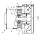
- FIG. 13 shows a cross-sectional view along the line XIII-XIII of FIG. 12 ;
- FIG. 14 shows an axonometric view of a mill similar to that of FIG. 11 where, for greater clarity, some accessory parts have been removed.
- a mill for grinding waste or rubbish R is denoted in its entirety by 20 .
- the mill 20 comprises at least one grinding chamber 22 defined by a side wall 24 and a floor 26 .
- the mill 20 also comprises at least two rotors 30 1 and 30 2 rotatable about respective substantially vertical axes X 1 and X 2 .
- Each of the rotors 30 comprises a hub 32 and a plurality of chains 34 connected to the hub 32 and designed to sweep over part of the grinding chamber 22 during rotation of the rotor 30 .
- each of the rotors 30 of the mill 20 defines a specific axis of rotation X.
- X is understood as meaning the direction of any straight line parallel to the axis X.
- RV is understood as meaning the direction of any straight half-line which has its origin on the axis X and is perpendicular thereto.
- Circumferential (or “tangential”) is understood as meaning the direction of any (straight line tangential to a) circumference centred on the axis X and arranged in a plane perpendicular thereto.
- the mill 20 is also subject to the acceleration of gravity indicated in FIG. 2 by the vector g.
- the description below refers, except where specifically indicated otherwise, to the mill 20 in the working configuration, i.e. the common concepts of vertical, horizontal, high, low, etc. are specifically defined with reference to the acceleration of gravity g.
- the grinding chamber 22 has internally a number of grinding volumes 28 corresponding to the number of rotors 30 present in the mill 20 .
- the grinding volume 28 of a specific rotor 30 is defined here as being the volume, included inside the grinding chamber 22 , defined by axially interpolating the circumferences inside which the chains 34 of that specific rotor 30 rotate. This volume is by its nature characterized by a rotational symmetry about the respective axis X. According to the embodiments shown in the accompanying figures, all the chains 34 of a single rotor 30 have an identical length and therefore the grinding volumes 28 assume the form of straight circular cylinders.
- said volumes assume other forms which arc considered to be suitable for managing the flow of waste R inside the mill 20 .
- the grinding volumes 28 of the rotors 30 are separate from each other.
- the grinding chamber 22 is obtained from the net sum of the grinding volumes 28 of the single rotors 30 .
- the side wall 24 is therefore shaped so as to follow precisely the profile of the grinding volumes 28 and therefore that of the grinding chamber 22 . It can be seen how in the accompanying figures, for greater clarity, a relatively large distance is shown between the radial ends of the chains 34 and the side wall 24 . In reality this distance is decidedly smaller. Similarly, in the accompanying FIGS. 2 and 7 , for greater clarity, a relatively large distance is shown between the grinding volume 28 and the side wall 24 which follows its profile. In reality this distance is decidedly smaller.
- the grinding chamber 22 is obtained from the sum of the grinding volumes 28 of the three rotors 30 plus a number of connecting volumes. In other words there are some portions of the plan area of the grinding chamber 22 which are not included within any of the grinding volumes 28 and which therefore are not affected by rotation of a chain 34 .
- the grinding volumes 28 of the mill in FIG. 20 are entirely identical to those of the mill 20 shown in FIG. 4 , while the respective grinding chambers 22 are different. While the grinding chamber 22 of the mill 20 in FIG. 4 has a plan area consisting of three lobes following the grinding volumes 28 , the grinding chamber 22 of the mill 20 according to FIG. 5 has a circular plan area, bigger than the one above.
- the grinding chamber 22 has internally a number of obstacles 46 .
- These obstacles 46 fill the spaces of the grinding chambers 22 which do not belong to any of the grinding volumes. They may be considered as forming an ideal continuation of the side wall 24 .
- the presence of the obstacles 46 has a dual function. Firstly the obstacles prevent the accumulation of masses of waste at points in the grinding chamber 22 which are not reached by any chain 34 . The accumulation and consequent presence of waste R which is not subject to the action of the chains 34 would result in an overall reduction in the efficiency of the process. Moreover, the obstacles 46 offer further surfaces and edges suitable for generating the impacts necessary for breaking up the waste R.
- the axes of rotation X of the rotors 30 are fixed, both with respect to each other and with respect to the walls 24 of the grinding chamber 22 .
- the interaxial distance between two rotors 30 1 and 30 2 of a same mill 20 is fixed; therefore the axes X 1 and X 2 of the two rotors 30 1 and 30 2 cannot be either moved towards each other or away from each other.
- the side wall 24 is substantially vertical and has a cylindrical shape, at least along sections, while the floor 26 is substantially horizontal.
- the side wall 24 could for example be inclined so as to have a conical configuration along sections. This solution could for example be useful for taking into account the specific forms chosen during the design stage for the grinding volumes 28 of the rotors 30 .
- the floor 26 could be not flat, could be not horizontal or could be neither flat nor horizontal.
- the floor could for example have an inclined configuration, even only along sections. This solution could be useful in particular conditions for facilitating the expulsion of certain fractions of the waste R being processed inside the mill 20 .
- the grinding volumes 28 of the various rotors 30 are adjacent to each other in pairs, defining a tangency zone 38 via which the two volumes 28 communicate with each other.
- the tangency zones 38 there is no fixed obstacle which opposes the passage of material from the grinding volume 28 1 of one rotor 30 1 to the grinding volume 28 2 of the adjacent rotor 30 2 .
- the waste which starts to rotate inside the mill 20 according to the invention undergoes a further series of impacts which quickly reduce it to the desired particle size.
- the rotational movement of the chains 34 imparts a high circumferential velocity to the waste R and consequently subjects it to a high centrifugal acceleration.
- any waste which starts to rotate together with a chain 34 adheres to the side wall 24 and is conveyed along it in the circumferential direction as far as the tangency zone 38 where the side wall 24 follows a path different from that of the grinding volume 28 .
- the efficiency of this action may he aided by the sporadic presence, inside the mass of waste R to be treated, of bodies which cannot be ground. These bodies in fact maintain a high capacity for impact against other waste, causing breaking up thereof against the corner edge.
- the tangential velocity of the ends of the chains 34 is equal to about 270 km/h ⁇ 30%, the tangential velocity therefore ranging between about 190 km/h and about 350 km/h.
- the impact which occurs between the waste inside a mill such as that schematically shown in FIG. 8 occurs at a relative speed of about 540 km/h ⁇ 30%, defined by the sum of the tangential velocities of the waste propelled from the right-hand side and left-hand side; the velocity of the impacts therefore ranges between about 380 km/h and about 700 km/h.
- the chains 34 may be present in different numbers and may have different forms, sizes and weights.
- FIGS. 1 to 6 show only rotors with four chains 34 in which a single type of chain is used.
- FIG. 7 instead show in schematic form a number of possible variants of the chains 34 .
- the left-hand rotor uses six chains, while the right-hand chain uses eight chains. It is obviously possible for different numbers of chains to be used.
- a consideration which arises at the moment of choosing the number of chains 34 for each rotor 30 is that of balancing the rotor during rotation in order to prevent as far as possible the generation of vibrations which may be bothersome or even give rise to structural resonance.
- the left-hand rotor in FIG. 7 also comprises two chains provided with end hammers 36 .
- This solution may be particularly useful if the weight of the chain 34 is to be increased without increasing excessively the size of the links. In this way the inertial characteristics with regard to the capacity for impact on the mass of waste R and extension during rotation may be increased, without dispensing with the intermediate flexibility.
- the right-hand rotor Compared to the four chains 34 without end hammers 36 of the left-hand rotor, the right-hand rotor comprises four chains which are lighter and four chains which are heavier.
- FIG. 2 shows schematically a number of possible axial arrangements.
- the left-hand rotor clearly shows three chains 34 at three different heights, while the fourth chain, owing to the particular position of the hub 32 , is not visible.
- the right-hand rotor shows instead all four chains, from where it can be seen (owing to the particular choice performed in this case) a single chain occupies the highest position, a single chain occupies the lowest position, while two chains, which are diametrically opposite each other, share the intermediate position.
- the number of chains 34 for each rotor 30 may be chosen depending on the type of waste R which in any case must be processed inside the mill 20 .
- the chains 34 are in fact connected to the respective rotor 30 in a rigid, but removable manner. This solution, in addition to the possibility of varying the design parameters of the chains 34 used during grinding, also allows the worn or damaged chains 34 to be easily replaced.
- the grinding chamber 22 also comprises grilles 40 suitable for allowing expulsion of the ground waste during operation of the mill 20 .
- the fraction of waste which has already been ground and which has reached a sufficiently small particle size may be expelled from the grilles 40 during operation of the mill 20 .
- the grilles 40 occupy preferably the bottom part of the side wall 24 (as in the embodiment of FIG. 2 ) or part of the floor 26 (not shown in the figures).
- FIG. 7 shows schematically the angle ⁇ over which the grilles 40 extend.
- the angle ⁇ may be advantageously between 90° and 270°.
- a wider angle ⁇ allows easier and faster removal of the already ground waste, therefore reducing its dwell time inside the grinding chamber 22 .
- the grilles 40 divide the grinding chamber 22 from one or more suction chambers 48 which are kept under a vacuum by means of a suction plant 50 .
- the floor of the suction chambers 48 communicates with a feeder screw 52 designed to remove the already ground waste.
- the suction plant 50 comprises a calming chamber 54 inside which there is a substantial increase in the cross-section of the duct along which suction takes place.
- a bag filter 56 is provided downstream of the calming chamber 54 .
- the bag filter 56 is kept operating efficiently in a known manner for example by means of periodic shaking movements which cause the accumulated particles to fall.
- the particles conveyed by the air flow and captured by the calming chamber 54 and by the bag filter 56 are then reconveyed to the main flow of the already ground waste R, for example to the feeder screws 52 .
- the mill 20 according to the invention comprises at least one hatch 42 for allowing periodic removal of the non-grindable bodies.
- FIG. 7 also shows one of the possible configurations for driving the mill 20 .
- each of the two rotors 30 is rotated, via a belt drive, by an associated motor 44 .
- the motor 44 is instead contained inside the associated hub 12 , in a configuration which is commonly known as a direct drive.
- This configuration offers various advantages compared to the configurations described above, said advantages being due in particular to the elimination of any form of mechanical drive. Above all the system is simpler and therefore ensures a greater degree of reliability and greater efficiency. The mechanical simplicity also reduces the manufacturing and management costs.
- the motor 44 must be able to impart directly the correct angular velocity to the rotor 30 .
- the speed of rotation of the motor 44 must therefore be electronically controlled so that it can be kept within the desired values.
- the speed of rotation of the motor 44 must be about 573 rpm during normal operation.
- the speed of rotation of the motor 44 during normal operation must be different so as to be able to keep the value of the tangential velocity of the ends of the chains 34 to within the desired values.
- the motor 44 is preferably a “torque motor”, i.e. a motor which is able to develop a high torque also at a low speed of rotation.
- These torque motors are usually synchronous permanent-magnet motors, preferably of the three-phase type.
- adjustment of the speed of rotation of the motor 44 may be achieved in a known manner by means of an inverter.
- removal of the non-grindable bodies is performed by means of automatic opening of the hatch 42 .
- Automatic opening may be for example controlled by the power consumption of the motor 44 : when the motor tends towards a consumption which exceeds a predefined threshold, it can be concluded that the chains 34 are dragging along the floor 26 a considerable quantity of non-grindable bodies.
- the hatch 42 is automatically opened for a few seconds, i.e. the time needed to allow expulsion of the non-grindable bodies by means of the centrifugal force.
- the power threshold value may be defined at the design stage by the mill manufacturer or, more advantageously, by the user of the mill. In this way it is in fact possible to take into account the specific characteristics of the different types of waste mass which may be processed.
- automatic opening of the hatch 42 may be controlled by a system for detecting the temperature in the rotating mass of waste R.
- a system for detecting the temperature in the rotating mass of waste R When an increase in the temperature is recorded, it can be deduced that a certain quantity of non-grindable bodies is rotating together with the waste and the friction which is produced as a result increases the temperature at least locally.
- a threshold temperature When a threshold temperature is reached or when a threshold gradient in the temperature increase is recorded, the hatch 42 is automatically opened for a few seconds, i.e. the time needed to allow expulsion of the non-grindable bodies by means of the centrifugal force.
- the threshold temperature and/or its threshold gradient may be defined at the design stage by the mill manufacturer or, more advantageously, by the user of the mill. In this way it is in fact possible to take into account the specific characteristics of the different types of waste mass which may be processed.
- automatic opening of the hatch 42 may be controlled by an algorithm which takes into consideration the power consumption of the motor 44 . the temperature of the waste R and/or the temperature gradient.
- the present invention also relates to a plant for recycling energy from the waste.
- the plant comprises a mill 20 in accordance with that described above and a burner suitable for optimum combustion of the RDF produced by the mill.
- the burner is of the type widely known in the sector for recycling energy from waste and in particular RDF.
- the mill 20 according to the present invention is suitable for grinding different types of waste. It is in fact particularly suitable for grinding MSW, but is also suitable for WEEE and other types of solid waste.
- the mill 20 according to the present invention has an energy efficiency which is decidedly greater than that of the mills of the known type. It should be considered in this connection that a specific study carried out by the Applicant has quantified an energy expenditure typically of less than 80 kW for each tonne of waste converted from MSW into RDF with a fine particle size (less than 5 mm).
- the mill 20 according to the invention has a simple and strong structure which is able to withstand the presence of non-grindable material.
- the present invention provides a mill which allows a reduction in the bacterial content present in the MSW treated inside it.
- the presence of the MSW inside the grinding chamber and the amount of mechanical energy used by it cause a gradual increase in its temperature, in a similar manner to that already described in connection with the mills of the known type.
- easy expulsion of the non-grindable bodies and the continuous mixing achieved by the chains drastically limit the temperature peaks and at the same time distribute the heat within the entire mass of MSW being processed.
- the temperature generally settles in the range of about 60-80° C., without therefore any problem as regards softening of the thermoplastic fractions and the consequent blockage of the grilles.
- the effect which such heating has on the MSW is that of a treatment similar to pasteurization, i.e. a treatment where the bacterial, content is drastically reduced (by about 90%).
- the embodiment comprising two rotors 30 (shown for example in FIGS. 1, 2, 7 to 9 , and 11 to 14 ) is the basic embodiment of the mill 20 . It ensures all the advantages mentioned above and therefore represents a substantial improvement compared to the mills of the known type.
- the embodiment comprising three rotors in line (shown for example in FIGS. 3 and 12 ) represents a further improvement.
- this embodiment is particularly effective since, while there is an increase in the size and number of components compared to the two-rotor version, the disposal capacity which can be achieved with it is significantly greater.
- a series of several machines is envisaged: a primary crusher (which initially breaks up the waste R into larger size pieces), a secondary crusher provided with blades situated closer together so as to reduce the size of the pieces, and finally a blade crusher for obtaining the final particle size of about 25 mm.
- the mill according to the present invention instead, the production of RDF is performed in a single pass.
- the mill according to the invention is able to process the waste mass as such, i.e. as supplied by the waste collection services, without any intermediate treatment.
- the mill alone according to the invention is able to achieve proper pulverization thereof: most of the RDF being output has a powdery and/or filamentous consistency and size.
- the mill 20 according to the invention represents a decidedly advantageous solution compared to the plants of the known type.
Applications Claiming Priority (4)
| Application Number | Priority Date | Filing Date | Title |
|---|---|---|---|
| ITMI2011A0320 | 2011-03-01 | ||
| ITMI2011A000320 | 2011-03-01 | ||
| IT000320A ITMI20110320A1 (it) | 2011-03-01 | 2011-03-01 | Mulino per rifiuti |
| PCT/IB2012/050591 WO2012117307A1 (en) | 2011-03-01 | 2012-02-09 | Mill for grinding rubbish |
Publications (2)
| Publication Number | Publication Date |
|---|---|
| US20130305969A1 US20130305969A1 (en) | 2013-11-21 |
| US9327286B2 true US9327286B2 (en) | 2016-05-03 |
Family
ID=43976993
Family Applications (1)
| Application Number | Title | Priority Date | Filing Date |
|---|---|---|---|
| US13/983,250 Active 2033-01-23 US9327286B2 (en) | 2011-03-01 | 2012-02-09 | Mill for grinding rubbish |
Country Status (18)
| Country | Link |
|---|---|
| US (1) | US9327286B2 (es) |
| EP (3) | EP2635379A1 (es) |
| CN (1) | CN103402643B (es) |
| CY (2) | CY1117982T1 (es) |
| DK (2) | DK2732880T3 (es) |
| EA (1) | EA201370168A1 (es) |
| ES (2) | ES2589886T3 (es) |
| HK (1) | HK1194027A1 (es) |
| HR (2) | HRP20161119T1 (es) |
| HU (2) | HUE030596T2 (es) |
| IT (1) | ITMI20110320A1 (es) |
| LT (2) | LT2732879T (es) |
| PL (2) | PL2732880T3 (es) |
| PT (2) | PT2732880T (es) |
| RS (2) | RS55109B1 (es) |
| SI (2) | SI2732880T1 (es) |
| SM (2) | SMT201600299B (es) |
| WO (1) | WO2012117307A1 (es) |
Cited By (2)
| Publication number | Priority date | Publication date | Assignee | Title |
|---|---|---|---|---|
| US20150048187A1 (en) * | 2013-08-13 | 2015-02-19 | TARTECH eco industries AG | Slag Breaker |
| US11744404B2 (en) * | 2018-01-26 | 2023-09-05 | G&E Innovations, Inc. | Grinder |
Families Citing this family (9)
| Publication number | Priority date | Publication date | Assignee | Title |
|---|---|---|---|---|
| DE102009045613A1 (de) * | 2009-10-13 | 2011-04-21 | Voith Patent Gmbh | Stofflöser |
| DE102013110352A1 (de) * | 2013-09-19 | 2015-03-19 | Pms Handelskontor Gmbh | Zerkleinerungsvorrichtung |
| CN103552715B (zh) * | 2013-11-15 | 2016-09-14 | 西安德兆环保科技有限公司 | 一种垃圾破袋机及利用其进行破袋的方法 |
| DE202014008874U1 (de) * | 2014-11-10 | 2015-02-19 | Huning Maschinenbau Gmbh | Vorrichtung zur Aufbereitung von insbesondere Biomassematerialien |
| WO2017035578A1 (en) | 2015-08-28 | 2017-03-09 | Tecfarm Pty Ltd | Apparatus and method for processing a crop residue |
| CN109513490A (zh) * | 2018-12-29 | 2019-03-26 | 厦门市环境能源投资发展有限公司 | 一种厨余垃圾链式破碎装置 |
| KR102034413B1 (ko) * | 2019-07-04 | 2019-11-18 | 주식회사 아진피앤피 | 제지용 분해장치 |
| IT201900011376A1 (it) * | 2019-07-10 | 2021-01-10 | Itea Spa | Procedimento e dispositivo per la macinazione di matrici eterogenee |
| US11516970B2 (en) * | 2019-10-30 | 2022-12-06 | Raymond Boone | Agricultural shredder |
Citations (24)
| Publication number | Priority date | Publication date | Assignee | Title |
|---|---|---|---|---|
| US359630A (en) | 1887-03-22 | Geanville c | ||
| US1351711A (en) * | 1919-01-28 | 1920-08-31 | White Samuel Jessie | Potato-peeler |
| US1439581A (en) * | 1920-12-08 | 1922-12-19 | Sedberry James Bernard | Grinding mill |
| US1728976A (en) * | 1927-10-03 | 1929-09-24 | Harry M Nobis | Apparatus for pulverizing coal |
| US3161412A (en) * | 1963-02-26 | 1964-12-15 | Starline | Material unloader and spreader with extensible flails |
| US3342426A (en) * | 1965-04-16 | 1967-09-19 | Sr Walter J Sackett | Pulverizing mill |
| US3606265A (en) | 1969-04-03 | 1971-09-20 | Herbert T Cobey | Fragmentizing apparatus with vertically mounted drum |
| US3993256A (en) * | 1975-08-28 | 1976-11-23 | Garbalizer Corporation Of America | Waste mangler system and structure |
| US4572258A (en) * | 1985-01-24 | 1986-02-25 | Mischel Kenneth J | Chain flail |
| US4654938A (en) * | 1983-03-22 | 1987-04-07 | Dalseide & Co. | Descaler head assembly for a descaling machine |
| US4947906A (en) * | 1987-12-01 | 1990-08-14 | H L & H Timber Products | Debarker |
| US5148844A (en) * | 1992-02-12 | 1992-09-22 | Chiparvestors, Inc. | Flail drum system |
| US5184781A (en) * | 1992-01-14 | 1993-02-09 | James Andela | Glass pulverizer |
| CN2152602Y (zh) | 1993-08-11 | 1994-01-12 | 徐世均 | 垃圾处理机 |
| US5322104A (en) * | 1993-05-04 | 1994-06-21 | Wood Technology, Inc. | Flail drum machines and methods |
| US5522913A (en) * | 1991-04-18 | 1996-06-04 | Tucker Hughes, Inc. | Process and machines for transforming household waste |
| US5630556A (en) * | 1995-11-07 | 1997-05-20 | Chrestenson; Robert A. | Portable apparatus for comminuting gypsum wallboard |
| US5697563A (en) * | 1994-08-22 | 1997-12-16 | Kabushiki Kaisha Fujimoto Pollcon | Chain beating type crusher |
| US6039277A (en) * | 1998-11-06 | 2000-03-21 | Hamm; Robert L. | Pulverizer |
| IT1317056B1 (it) | 2000-07-07 | 2003-05-26 | Assing S P A | Procedimento per la trasformazione di rifiuti solidi urbani inmateriali solidi combustibili. |
| US20060124787A1 (en) | 2002-08-29 | 2006-06-15 | Helmut Schweiger | Comminuting device |
| CN201109766Y (zh) | 2007-09-22 | 2008-09-03 | 周开根 | 用垃圾、生物质原料生产二甲醚的设备系统 |
| EP2062645A1 (de) | 2007-11-26 | 2009-05-27 | Anlagenbau Umwelt + Technik Chemnitz GmbH | Zerkleinerungsvorrichtung |
| US7891593B2 (en) * | 2005-09-28 | 2011-02-22 | Get Hamburg Gmbh | Device for comminuting a heap of particulate material |
Family Cites Families (3)
| Publication number | Priority date | Publication date | Assignee | Title |
|---|---|---|---|---|
| CN1069556C (zh) * | 1994-08-22 | 2001-08-15 | 株式会社富士本波尔肯 | 锁链打击式破碎机 |
| JP2704503B2 (ja) * | 1995-02-10 | 1998-01-26 | 和雄 平川 | 破砕装置 |
| DE102008038045B4 (de) * | 2008-08-16 | 2011-07-14 | Suchy, Martin, 58791 | Vorrichtung zur Aufbereitung von Asphaltaufbruch |
-
2011
- 2011-03-01 IT IT000320A patent/ITMI20110320A1/it unknown
-
2012
- 2012-02-09 CN CN201280010617.0A patent/CN103402643B/zh not_active Expired - Fee Related
- 2012-02-09 HU HUE14155432A patent/HUE030596T2/en unknown
- 2012-02-09 WO PCT/IB2012/050591 patent/WO2012117307A1/en active Application Filing
- 2012-02-09 DK DK14155445.1T patent/DK2732880T3/en active
- 2012-02-09 EP EP12707922.6A patent/EP2635379A1/en not_active Withdrawn
- 2012-02-09 US US13/983,250 patent/US9327286B2/en active Active
- 2012-02-09 DK DK14155432.9T patent/DK2732879T3/en active
- 2012-02-09 ES ES14155432.9T patent/ES2589886T3/es active Active
- 2012-02-09 LT LTEP14155432.9T patent/LT2732879T/lt unknown
- 2012-02-09 SI SI201230698A patent/SI2732880T1/sl unknown
- 2012-02-09 PL PL14155445T patent/PL2732880T3/pl unknown
- 2012-02-09 HU HUE14155445A patent/HUE030628T2/en unknown
- 2012-02-09 SI SI201230696A patent/SI2732879T1/sl unknown
- 2012-02-09 PL PL14155432T patent/PL2732879T3/pl unknown
- 2012-02-09 EP EP14155432.9A patent/EP2732879B8/en active Active
- 2012-02-09 RS RS20160735A patent/RS55109B1/sr unknown
- 2012-02-09 EA EA201370168A patent/EA201370168A1/ru unknown
- 2012-02-09 LT LTEP14155445.1T patent/LT2732880T/lt unknown
- 2012-02-09 ES ES14155445.1T patent/ES2589765T3/es active Active
- 2012-02-09 PT PT141554451T patent/PT2732880T/pt unknown
- 2012-02-09 PT PT141554329T patent/PT2732879T/pt unknown
- 2012-02-09 RS RS20160736A patent/RS55110B1/sr unknown
- 2012-02-09 EP EP14155445.1A patent/EP2732880B8/en active Active
-
2014
- 2014-02-27 HK HK14107557.4A patent/HK1194027A1/zh not_active IP Right Cessation
-
2016
- 2016-09-01 HR HRP20161119TT patent/HRP20161119T1/hr unknown
- 2016-09-01 HR HRP20161120TT patent/HRP20161120T1/hr unknown
- 2016-09-02 SM SM201600299T patent/SMT201600299B/it unknown
- 2016-09-02 SM SM201600300T patent/SMT201600300B/it unknown
- 2016-09-07 CY CY20161100887T patent/CY1117982T1/el unknown
- 2016-09-07 CY CY20161100888T patent/CY1117983T1/el unknown
Patent Citations (24)
| Publication number | Priority date | Publication date | Assignee | Title |
|---|---|---|---|---|
| US359630A (en) | 1887-03-22 | Geanville c | ||
| US1351711A (en) * | 1919-01-28 | 1920-08-31 | White Samuel Jessie | Potato-peeler |
| US1439581A (en) * | 1920-12-08 | 1922-12-19 | Sedberry James Bernard | Grinding mill |
| US1728976A (en) * | 1927-10-03 | 1929-09-24 | Harry M Nobis | Apparatus for pulverizing coal |
| US3161412A (en) * | 1963-02-26 | 1964-12-15 | Starline | Material unloader and spreader with extensible flails |
| US3342426A (en) * | 1965-04-16 | 1967-09-19 | Sr Walter J Sackett | Pulverizing mill |
| US3606265A (en) | 1969-04-03 | 1971-09-20 | Herbert T Cobey | Fragmentizing apparatus with vertically mounted drum |
| US3993256A (en) * | 1975-08-28 | 1976-11-23 | Garbalizer Corporation Of America | Waste mangler system and structure |
| US4654938A (en) * | 1983-03-22 | 1987-04-07 | Dalseide & Co. | Descaler head assembly for a descaling machine |
| US4572258A (en) * | 1985-01-24 | 1986-02-25 | Mischel Kenneth J | Chain flail |
| US4947906A (en) * | 1987-12-01 | 1990-08-14 | H L & H Timber Products | Debarker |
| US5522913A (en) * | 1991-04-18 | 1996-06-04 | Tucker Hughes, Inc. | Process and machines for transforming household waste |
| US5184781A (en) * | 1992-01-14 | 1993-02-09 | James Andela | Glass pulverizer |
| US5148844A (en) * | 1992-02-12 | 1992-09-22 | Chiparvestors, Inc. | Flail drum system |
| US5322104A (en) * | 1993-05-04 | 1994-06-21 | Wood Technology, Inc. | Flail drum machines and methods |
| CN2152602Y (zh) | 1993-08-11 | 1994-01-12 | 徐世均 | 垃圾处理机 |
| US5697563A (en) * | 1994-08-22 | 1997-12-16 | Kabushiki Kaisha Fujimoto Pollcon | Chain beating type crusher |
| US5630556A (en) * | 1995-11-07 | 1997-05-20 | Chrestenson; Robert A. | Portable apparatus for comminuting gypsum wallboard |
| US6039277A (en) * | 1998-11-06 | 2000-03-21 | Hamm; Robert L. | Pulverizer |
| IT1317056B1 (it) | 2000-07-07 | 2003-05-26 | Assing S P A | Procedimento per la trasformazione di rifiuti solidi urbani inmateriali solidi combustibili. |
| US20060124787A1 (en) | 2002-08-29 | 2006-06-15 | Helmut Schweiger | Comminuting device |
| US7891593B2 (en) * | 2005-09-28 | 2011-02-22 | Get Hamburg Gmbh | Device for comminuting a heap of particulate material |
| CN201109766Y (zh) | 2007-09-22 | 2008-09-03 | 周开根 | 用垃圾、生物质原料生产二甲醚的设备系统 |
| EP2062645A1 (de) | 2007-11-26 | 2009-05-27 | Anlagenbau Umwelt + Technik Chemnitz GmbH | Zerkleinerungsvorrichtung |
Non-Patent Citations (2)
| Title |
|---|
| Italian Search Report and Written Opinion dated Oct. 14, 2011 for related IT App. No. MI20110320, 7 pgs. |
| PCT International Search Report and Written Opinion dated Jul. 3, 2012 for Intl. App. No. PCT/IB2012/050591, from which the instant application is based, 8 pgs. |
Cited By (2)
| Publication number | Priority date | Publication date | Assignee | Title |
|---|---|---|---|---|
| US20150048187A1 (en) * | 2013-08-13 | 2015-02-19 | TARTECH eco industries AG | Slag Breaker |
| US11744404B2 (en) * | 2018-01-26 | 2023-09-05 | G&E Innovations, Inc. | Grinder |
Also Published As
Similar Documents
| Publication | Publication Date | Title |
|---|---|---|
| US9327286B2 (en) | Mill for grinding rubbish | |
| US8777142B2 (en) | Device for mechanical separation of material conglomerates from materials of different density and/or consistency | |
| CN102698845B (zh) | 卧式碎浆机 | |
| KR101787666B1 (ko) | 폐기물 파쇄장치 | |
| CN205518148U (zh) | 一种生物医药生产用高效粉碎机 | |
| US9498780B2 (en) | Grinding mill with cable grinding arms | |
| CN104941769B (zh) | 一种固体物料研磨方法及固体物料研磨机 | |
| CN109107738A (zh) | 10000马力废钢破碎生产线 | |
| CN203494599U (zh) | 一种冲击式破碎机 | |
| AU2010300248A1 (en) | Method and device for comminuting ore | |
| CN212791460U (zh) | 一种粉体分离机 | |
| CN206631721U (zh) | 一种新型泡沫粉碎机 | |
| CN106000542B (zh) | 一种餐厨垃圾分选破碎一体机及方法 | |
| CN107282320A (zh) | 双鼠笼磨煤机分离器 | |
| CN114405631A (zh) | 一种粉碎机 | |
| CN107597354A (zh) | 一种高效气流粉碎机 | |
| CN203678463U (zh) | 一种粉碎机 | |
| CN209156087U (zh) | 10000马力废钢破碎生产线 | |
| CN203470131U (zh) | 带微细分级机的无筛超微粉碎机 | |
| CN107694684A (zh) | 一种破碎器 | |
| CN206897612U (zh) | 一种破碎提升装置 | |
| CN206316034U (zh) | 垃圾分选离心机 | |
| CN105032554B (zh) | 驱动物料相互撞击破碎的设备 | |
| CN217725765U (zh) | 一种粉碎机 | |
| CN207913891U (zh) | 一种环锤数量和速度控制装置及应用其的电厂环锤破碎机 |
Legal Events
| Date | Code | Title | Description |
|---|---|---|---|
| AS | Assignment |
Owner name: CHRYSOPOEIA SRL, ITALY Free format text: ASSIGNMENT OF ASSIGNORS INTEREST;ASSIGNORS:TREBUCCHI, PIERVITTORIO;EICH, NORBERT;ZUBANI, LORENZO;REEL/FRAME:031926/0346 Effective date: 20130710 |
|
| STCF | Information on status: patent grant |
Free format text: PATENTED CASE |
|
| MAFP | Maintenance fee payment |
Free format text: PAYMENT OF MAINTENANCE FEE, 4TH YR, SMALL ENTITY (ORIGINAL EVENT CODE: M2551); ENTITY STATUS OF PATENT OWNER: SMALL ENTITY Year of fee payment: 4 |
|
| FEPP | Fee payment procedure |
Free format text: MAINTENANCE FEE REMINDER MAILED (ORIGINAL EVENT CODE: REM.); ENTITY STATUS OF PATENT OWNER: SMALL ENTITY |