US9324597B2 - Vertical inline CVD system - Google Patents
Vertical inline CVD system Download PDFInfo
- Publication number
- US9324597B2 US9324597B2 US13/098,255 US201113098255A US9324597B2 US 9324597 B2 US9324597 B2 US 9324597B2 US 201113098255 A US201113098255 A US 201113098255A US 9324597 B2 US9324597 B2 US 9324597B2
- Authority
- US
- United States
- Prior art keywords
- chamber body
- coupled
- waveguide
- processing
- substrates
- Prior art date
- Legal status (The legal status is an assumption and is not a legal conclusion. Google has not performed a legal analysis and makes no representation as to the accuracy of the status listed.)
- Expired - Fee Related, expires
Links
Images


Classifications
-
- C—CHEMISTRY; METALLURGY
- C23—COATING METALLIC MATERIAL; COATING MATERIAL WITH METALLIC MATERIAL; CHEMICAL SURFACE TREATMENT; DIFFUSION TREATMENT OF METALLIC MATERIAL; COATING BY VACUUM EVAPORATION, BY SPUTTERING, BY ION IMPLANTATION OR BY CHEMICAL VAPOUR DEPOSITION, IN GENERAL; INHIBITING CORROSION OF METALLIC MATERIAL OR INCRUSTATION IN GENERAL
- C23C—COATING METALLIC MATERIAL; COATING MATERIAL WITH METALLIC MATERIAL; SURFACE TREATMENT OF METALLIC MATERIAL BY DIFFUSION INTO THE SURFACE, BY CHEMICAL CONVERSION OR SUBSTITUTION; COATING BY VACUUM EVAPORATION, BY SPUTTERING, BY ION IMPLANTATION OR BY CHEMICAL VAPOUR DEPOSITION, IN GENERAL
- C23C16/00—Chemical coating by decomposition of gaseous compounds, without leaving reaction products of surface material in the coating, i.e. chemical vapour deposition [CVD] processes
- C23C16/44—Chemical coating by decomposition of gaseous compounds, without leaving reaction products of surface material in the coating, i.e. chemical vapour deposition [CVD] processes characterised by the method of coating
- C23C16/50—Chemical coating by decomposition of gaseous compounds, without leaving reaction products of surface material in the coating, i.e. chemical vapour deposition [CVD] processes characterised by the method of coating using electric discharges
-
- H—ELECTRICITY
- H10—SEMICONDUCTOR DEVICES; ELECTRIC SOLID-STATE DEVICES NOT OTHERWISE PROVIDED FOR
- H10P—GENERIC PROCESSES OR APPARATUS FOR THE MANUFACTURE OR TREATMENT OF DEVICES COVERED BY CLASS H10
- H10P72/00—Handling or holding of wafers, substrates or devices during manufacture or treatment thereof
- H10P72/30—Handling or holding of wafers, substrates or devices during manufacture or treatment thereof for conveying, e.g. between different workstations
- H10P72/32—Handling or holding of wafers, substrates or devices during manufacture or treatment thereof for conveying, e.g. between different workstations between different workstations
- H10P72/3206—Handling or holding of wafers, substrates or devices during manufacture or treatment thereof for conveying, e.g. between different workstations between different workstations the substrate being handled substantially vertically
-
- H01L21/67712—
-
- C—CHEMISTRY; METALLURGY
- C23—COATING METALLIC MATERIAL; COATING MATERIAL WITH METALLIC MATERIAL; CHEMICAL SURFACE TREATMENT; DIFFUSION TREATMENT OF METALLIC MATERIAL; COATING BY VACUUM EVAPORATION, BY SPUTTERING, BY ION IMPLANTATION OR BY CHEMICAL VAPOUR DEPOSITION, IN GENERAL; INHIBITING CORROSION OF METALLIC MATERIAL OR INCRUSTATION IN GENERAL
- C23C—COATING METALLIC MATERIAL; COATING MATERIAL WITH METALLIC MATERIAL; SURFACE TREATMENT OF METALLIC MATERIAL BY DIFFUSION INTO THE SURFACE, BY CHEMICAL CONVERSION OR SUBSTITUTION; COATING BY VACUUM EVAPORATION, BY SPUTTERING, BY ION IMPLANTATION OR BY CHEMICAL VAPOUR DEPOSITION, IN GENERAL
- C23C16/00—Chemical coating by decomposition of gaseous compounds, without leaving reaction products of surface material in the coating, i.e. chemical vapour deposition [CVD] processes
- C23C16/44—Chemical coating by decomposition of gaseous compounds, without leaving reaction products of surface material in the coating, i.e. chemical vapour deposition [CVD] processes characterised by the method of coating
- C23C16/458—Chemical coating by decomposition of gaseous compounds, without leaving reaction products of surface material in the coating, i.e. chemical vapour deposition [CVD] processes characterised by the method of coating characterised by the method used for supporting substrates in the reaction chamber
- C23C16/4582—Rigid and flat substrates, e.g. plates or discs
- C23C16/4587—Rigid and flat substrates, e.g. plates or discs the substrate being supported substantially vertically
-
- C—CHEMISTRY; METALLURGY
- C23—COATING METALLIC MATERIAL; COATING MATERIAL WITH METALLIC MATERIAL; CHEMICAL SURFACE TREATMENT; DIFFUSION TREATMENT OF METALLIC MATERIAL; COATING BY VACUUM EVAPORATION, BY SPUTTERING, BY ION IMPLANTATION OR BY CHEMICAL VAPOUR DEPOSITION, IN GENERAL; INHIBITING CORROSION OF METALLIC MATERIAL OR INCRUSTATION IN GENERAL
- C23C—COATING METALLIC MATERIAL; COATING MATERIAL WITH METALLIC MATERIAL; SURFACE TREATMENT OF METALLIC MATERIAL BY DIFFUSION INTO THE SURFACE, BY CHEMICAL CONVERSION OR SUBSTITUTION; COATING BY VACUUM EVAPORATION, BY SPUTTERING, BY ION IMPLANTATION OR BY CHEMICAL VAPOUR DEPOSITION, IN GENERAL
- C23C16/00—Chemical coating by decomposition of gaseous compounds, without leaving reaction products of surface material in the coating, i.e. chemical vapour deposition [CVD] processes
- C23C16/44—Chemical coating by decomposition of gaseous compounds, without leaving reaction products of surface material in the coating, i.e. chemical vapour deposition [CVD] processes characterised by the method of coating
- C23C16/46—Chemical coating by decomposition of gaseous compounds, without leaving reaction products of surface material in the coating, i.e. chemical vapour deposition [CVD] processes characterised by the method of coating characterised by the method used for heating the substrate
- C23C16/463—Cooling of the substrate
-
- C—CHEMISTRY; METALLURGY
- C23—COATING METALLIC MATERIAL; COATING MATERIAL WITH METALLIC MATERIAL; CHEMICAL SURFACE TREATMENT; DIFFUSION TREATMENT OF METALLIC MATERIAL; COATING BY VACUUM EVAPORATION, BY SPUTTERING, BY ION IMPLANTATION OR BY CHEMICAL VAPOUR DEPOSITION, IN GENERAL; INHIBITING CORROSION OF METALLIC MATERIAL OR INCRUSTATION IN GENERAL
- C23C—COATING METALLIC MATERIAL; COATING MATERIAL WITH METALLIC MATERIAL; SURFACE TREATMENT OF METALLIC MATERIAL BY DIFFUSION INTO THE SURFACE, BY CHEMICAL CONVERSION OR SUBSTITUTION; COATING BY VACUUM EVAPORATION, BY SPUTTERING, BY ION IMPLANTATION OR BY CHEMICAL VAPOUR DEPOSITION, IN GENERAL
- C23C16/00—Chemical coating by decomposition of gaseous compounds, without leaving reaction products of surface material in the coating, i.e. chemical vapour deposition [CVD] processes
- C23C16/44—Chemical coating by decomposition of gaseous compounds, without leaving reaction products of surface material in the coating, i.e. chemical vapour deposition [CVD] processes characterised by the method of coating
- C23C16/50—Chemical coating by decomposition of gaseous compounds, without leaving reaction products of surface material in the coating, i.e. chemical vapour deposition [CVD] processes characterised by the method of coating using electric discharges
- C23C16/511—Chemical coating by decomposition of gaseous compounds, without leaving reaction products of surface material in the coating, i.e. chemical vapour deposition [CVD] processes characterised by the method of coating using electric discharges using microwave discharges
-
- C—CHEMISTRY; METALLURGY
- C23—COATING METALLIC MATERIAL; COATING MATERIAL WITH METALLIC MATERIAL; CHEMICAL SURFACE TREATMENT; DIFFUSION TREATMENT OF METALLIC MATERIAL; COATING BY VACUUM EVAPORATION, BY SPUTTERING, BY ION IMPLANTATION OR BY CHEMICAL VAPOUR DEPOSITION, IN GENERAL; INHIBITING CORROSION OF METALLIC MATERIAL OR INCRUSTATION IN GENERAL
- C23C—COATING METALLIC MATERIAL; COATING MATERIAL WITH METALLIC MATERIAL; SURFACE TREATMENT OF METALLIC MATERIAL BY DIFFUSION INTO THE SURFACE, BY CHEMICAL CONVERSION OR SUBSTITUTION; COATING BY VACUUM EVAPORATION, BY SPUTTERING, BY ION IMPLANTATION OR BY CHEMICAL VAPOUR DEPOSITION, IN GENERAL
- C23C16/00—Chemical coating by decomposition of gaseous compounds, without leaving reaction products of surface material in the coating, i.e. chemical vapour deposition [CVD] processes
- C23C16/44—Chemical coating by decomposition of gaseous compounds, without leaving reaction products of surface material in the coating, i.e. chemical vapour deposition [CVD] processes characterised by the method of coating
- C23C16/54—Apparatus specially adapted for continuous coating
-
- H—ELECTRICITY
- H01—ELECTRIC ELEMENTS
- H01J—ELECTRIC DISCHARGE TUBES OR DISCHARGE LAMPS
- H01J37/00—Discharge tubes with provision for introducing objects or material to be exposed to the discharge, e.g. for the purpose of examination or processing thereof
- H01J37/32—Gas-filled discharge tubes
- H01J37/32009—Arrangements for generation of plasma specially adapted for examination or treatment of objects, e.g. plasma sources
- H01J37/32192—Microwave generated discharge
- H01J37/32211—Means for coupling power to the plasma
- H01J37/3222—Antennas
-
- H01L21/67126—
-
- H01L21/67173—
-
- H01L21/6719—
-
- H01L21/67201—
-
- H—ELECTRICITY
- H10—SEMICONDUCTOR DEVICES; ELECTRIC SOLID-STATE DEVICES NOT OTHERWISE PROVIDED FOR
- H10P—GENERIC PROCESSES OR APPARATUS FOR THE MANUFACTURE OR TREATMENT OF DEVICES COVERED BY CLASS H10
- H10P14/00—Formation of materials, e.g. in the shape of layers or pillars
- H10P14/20—Formation of materials, e.g. in the shape of layers or pillars of semiconductor materials
- H10P14/24—Formation of materials, e.g. in the shape of layers or pillars of semiconductor materials using chemical vapour deposition [CVD]
-
- H—ELECTRICITY
- H10—SEMICONDUCTOR DEVICES; ELECTRIC SOLID-STATE DEVICES NOT OTHERWISE PROVIDED FOR
- H10P—GENERIC PROCESSES OR APPARATUS FOR THE MANUFACTURE OR TREATMENT OF DEVICES COVERED BY CLASS H10
- H10P72/00—Handling or holding of wafers, substrates or devices during manufacture or treatment thereof
- H10P72/04—Apparatus for manufacture or treatment
- H10P72/0441—Apparatus for sealing, encapsulating, glassing, decapsulating or the like
-
- H—ELECTRICITY
- H10—SEMICONDUCTOR DEVICES; ELECTRIC SOLID-STATE DEVICES NOT OTHERWISE PROVIDED FOR
- H10P—GENERIC PROCESSES OR APPARATUS FOR THE MANUFACTURE OR TREATMENT OF DEVICES COVERED BY CLASS H10
- H10P72/00—Handling or holding of wafers, substrates or devices during manufacture or treatment thereof
- H10P72/04—Apparatus for manufacture or treatment
- H10P72/0451—Apparatus for manufacturing or treating in a plurality of work-stations
- H10P72/0452—Apparatus for manufacturing or treating in a plurality of work-stations characterised by the layout of the process chambers
- H10P72/0456—Apparatus for manufacturing or treating in a plurality of work-stations characterised by the layout of the process chambers in-line arrangement
-
- H—ELECTRICITY
- H10—SEMICONDUCTOR DEVICES; ELECTRIC SOLID-STATE DEVICES NOT OTHERWISE PROVIDED FOR
- H10P—GENERIC PROCESSES OR APPARATUS FOR THE MANUFACTURE OR TREATMENT OF DEVICES COVERED BY CLASS H10
- H10P72/00—Handling or holding of wafers, substrates or devices during manufacture or treatment thereof
- H10P72/04—Apparatus for manufacture or treatment
- H10P72/0451—Apparatus for manufacturing or treating in a plurality of work-stations
- H10P72/0462—Apparatus for manufacturing or treating in a plurality of work-stations characterised by the construction of the processing chambers, e.g. modular processing chambers
-
- H—ELECTRICITY
- H10—SEMICONDUCTOR DEVICES; ELECTRIC SOLID-STATE DEVICES NOT OTHERWISE PROVIDED FOR
- H10P—GENERIC PROCESSES OR APPARATUS FOR THE MANUFACTURE OR TREATMENT OF DEVICES COVERED BY CLASS H10
- H10P72/00—Handling or holding of wafers, substrates or devices during manufacture or treatment thereof
- H10P72/04—Apparatus for manufacture or treatment
- H10P72/0451—Apparatus for manufacturing or treating in a plurality of work-stations
- H10P72/0466—Apparatus for manufacturing or treating in a plurality of work-stations characterised by the construction of the load-lock chamber
-
- H—ELECTRICITY
- H01—ELECTRIC ELEMENTS
- H01J—ELECTRIC DISCHARGE TUBES OR DISCHARGE LAMPS
- H01J37/00—Discharge tubes with provision for introducing objects or material to be exposed to the discharge, e.g. for the purpose of examination or processing thereof
- H01J37/32—Gas-filled discharge tubes
- H01J37/32431—Constructional details of the reactor
- H01J37/32458—Vessel
- H01J37/32513—Sealing means, e.g. sealing between different parts of the vessel
-
- H—ELECTRICITY
- H01—ELECTRIC ELEMENTS
- H01J—ELECTRIC DISCHARGE TUBES OR DISCHARGE LAMPS
- H01J37/00—Discharge tubes with provision for introducing objects or material to be exposed to the discharge, e.g. for the purpose of examination or processing thereof
- H01J37/32—Gas-filled discharge tubes
- H01J37/32431—Constructional details of the reactor
- H01J37/32458—Vessel
- H01J37/32522—Temperature
-
- H—ELECTRICITY
- H01—ELECTRIC ELEMENTS
- H01J—ELECTRIC DISCHARGE TUBES OR DISCHARGE LAMPS
- H01J37/00—Discharge tubes with provision for introducing objects or material to be exposed to the discharge, e.g. for the purpose of examination or processing thereof
- H01J37/32—Gas-filled discharge tubes
- H01J37/32431—Constructional details of the reactor
- H01J37/32798—Further details of plasma apparatus not provided for in groups H01J37/3244 - H01J37/32788; special provisions for cleaning or maintenance of the apparatus
- H01J37/32889—Connection or combination with other apparatus
-
- H—ELECTRICITY
- H01—ELECTRIC ELEMENTS
- H01J—ELECTRIC DISCHARGE TUBES OR DISCHARGE LAMPS
- H01J37/00—Discharge tubes with provision for introducing objects or material to be exposed to the discharge, e.g. for the purpose of examination or processing thereof
- H01J37/32—Gas-filled discharge tubes
- H01J37/32431—Constructional details of the reactor
- H01J37/32798—Further details of plasma apparatus not provided for in groups H01J37/3244 - H01J37/32788; special provisions for cleaning or maintenance of the apparatus
- H01J37/32899—Multiple chambers, e.g. cluster tools
-
- H—ELECTRICITY
- H10—SEMICONDUCTOR DEVICES; ELECTRIC SOLID-STATE DEVICES NOT OTHERWISE PROVIDED FOR
- H10P—GENERIC PROCESSES OR APPARATUS FOR THE MANUFACTURE OR TREATMENT OF DEVICES COVERED BY CLASS H10
- H10P72/00—Handling or holding of wafers, substrates or devices during manufacture or treatment thereof
- H10P72/04—Apparatus for manufacture or treatment
- H10P72/0431—Apparatus for thermal treatment
Definitions
- Embodiments of the present invention generally relate to a vertical chemical vapor deposition (CVD) system.
- CVD chemical vapor deposition
- CVD is a process whereby chemical precursors are introduced into a processing chamber, chemically react to form a predetermined compound or material, and deposited onto a substrate within the processing chamber.
- CVD processes There are several CVD processes.
- One CVD process is plasma enhanced chemical vapor deposition (PECVD) whereby a plasma is ignited in the chamber to enhance the reaction between the precursors.
- PECVD may be accomplished by utilizing an inductively coupled plasma source or a capacitively coupled plasma source.
- the CVD process may be used to process large area substrates, such as flat panel displays or solar panels.
- CVD may be used to deposit layers such as silicon based films for transistors.
- the present invention generally relates to a vertical CVD system having a processing chamber that is capable of processing multiple substrates.
- the multiple substrates are disposed on opposite sides of the processing source within the processing chamber, yet the processing environments are not isolated from each other.
- the processing source is a horizontally centered vertical plasma generator that permits multiple substrates to be processed simultaneously on either side of the plasma generator, yet independent of each other.
- the system is arranged as a twin system whereby two identical processing lines, each with their own processing chamber, are arranged adjacent to each other. Multiple robots are used to load and unload the substrates from the processing system. Each robot can access both processing lines within the system.
- an apparatus in one embodiment, includes a chamber body, a plurality of plasma generators, a first waveguide coupled to the first end of each plasma generator, a second waveguide coupled to the second end of each plasma generator, a first power source coupled to the first waveguide, the first power source disposed outside of the chamber body, and a second power source coupled to the second waveguide.
- the plurality of plasma generators are horizontally centered within the chamber body and extend vertically within the chamber body such that sufficient space remains within the chamber body for one or more substrates to be processed on opposite sides of the plurality of plasma generators.
- Each plasma generator has a first end adjacent a bottom of the chamber body and a second end adjacent a top of the chamber body.
- the second power sources are disposed outside of the chamber body.
- the second power sources are collectively arranged in a staggered pattern such that adjacent second waveguides extend in opposite directions from the plasma generators to corresponding second power sources.
- an apparatus in another embodiment, includes a chamber body, a plurality of plasma generators, a first waveguide coupled to the first end of each plasma generator, a second waveguide coupled to the second end of each plasma generator, a first power source coupled to the first waveguide, the first power source disposed outside of the chamber body, and a second power source coupled to the second waveguide.
- the plurality of plasma generators are horizontally centered within the chamber body and extend vertically within the chamber body such that sufficient space remains within the chamber body for one or more substrates to be processed on opposite sides of the plurality of plasma generators.
- Each plasma generator has a first end adjacent a bottom of the chamber body and a second end adjacent a top of the chamber body.
- the second power sources are disposed outside of the chamber body.
- the second power sources are collectively arranged in a pattern such that adjacent second waveguides extend in the same direction from the plasma generators to corresponding second power sources.
- an apparatus in another embodiment, includes a chamber body, a plurality of plasma generators, a first angled waveguide coupled to the first end of each plasma generator, a second angled waveguide coupled to the second end of each plasma generator, a first power source coupled to the first waveguide, the first power source disposed outside of the chamber body, and a second power source coupled to the second waveguide.
- the plurality of plasma generators are horizontally centered within the chamber body and extend vertically within the chamber body such that sufficient space remains within the chamber body for one or more substrates to be processed on opposite sides of the plurality of plasma generators.
- Each plasma generator has a first end adjacent a bottom of the chamber body and a second end adjacent a top of the chamber body.
- the second power sources are disposed outside of the chamber body.
- the second power sources are collectively arranged in a staggered pattern such that each second waveguide extends up along a side of the chamber body and along a roof of the chamber body to the first end of each plasma generator.
- FIG. 1 is a schematic representation of a processing system according to one embodiment.
- FIG. 2 is a schematic top view of the processing system of FIG. 1 .
- FIG. 3 is a schematic side view of the processing system of FIG. 1 .
- FIG. 4 is a close-up view of the processing chamber of FIG. 1 .
- FIG. 5 is a schematic back view of the processing system of FIG. 1 .
- FIG. 6A is a schematic cross-sectional view of the processing chamber of FIG. 1 .
- FIG. 6B is a partial side view of the processing chamber of FIG. 1 .
- FIG. 7 is a schematic illustration of an evacuation system for the processing system of FIG. 1 .
- FIG. 8 is an isometric view of the processing chamber of FIG. 1 .
- FIG. 9 is a schematic top illustration of the substrate sequencing for the processing system of FIG. 1 .
- FIGS. 10A-10C are schematic representations of the processing chambers of FIG. 1 .
- FIGS. 11A and 11B are schematic representations of a processing chamber according to another embodiment.
- FIGS. 12A and 12B are schematic representations of a processing chamber according to another embodiment.
- FIGS. 13A and 13B are schematic representations of a processing chamber according to another embodiment.
- the present invention generally relates to a vertical CVD system having a processing chamber that is capable of processing multiple substrates.
- the multiple substrates are disposed on opposite sides of the processing source within the processing chamber, yet the processing environments are not isolated from each other.
- the processing source is a horizontally centered vertical plasma generator that permits multiple substrates to be processed simultaneously on either side of the plasma generator, yet independent of each other.
- the system is arranged as a twin system whereby two identical processing lines, each with their own processing chamber, are arranged adjacent to each other. Multiple robots are used to load and unload the substrates from the processing system. Each robot can access both processing lines within the system.
- a horizontally centered vertical plasma generator is a plasma generator that has a plasma source that is vertical within the processing chamber.
- the plasma source extends from a first end near or at the bottom of the chamber to a second end at near or at the top of the chamber.
- the plasma source is equally spaced between two walls or ends of the processing chamber.
- inventions discussed herein may be practiced utilizing a vertical CVD chamber in a modified AKT Aristo system available from Applied Materials, Inc., Santa Clara, Calif. It is to be understood that the embodiments may be practiced in other systems as well, including those sold by other manufacturers.
- FIG. 1 is a schematic representation of a vertical, linear CVD system 100 according to one embodiment.
- the system 100 may be sized to process substrates having a surface area of greater than about 90,000 mm 2 and able to process more than 90 substrates per hour when depositing a 2,000 Angstrom thick silicon nitride film.
- the system 100 preferably includes two separate process lines 114 A, 114 B coupled together by a common system control platform 112 to form a twin process line configuration/layout.
- a common power supply such as an AC power supply
- common and/or shared pumping and exhaust components and a common gas panel may be used for the twin process lines 114 A, 114 B.
- Each process line 114 A, 114 B may process more than 45 substrates per hour for a system total of greater than 90 substrates per hour. It is also contemplated that the system may be configured using a single process line or more than two process lines.
- twin processing lines 114 A, 114 B for vertical substrate processing. Because the chambers are arranged vertically, the footprint of the system 100 is about the same as a single, conventional horizontal processing line. Thus, within approximately the same footprint, two processing lines 114 A, 114 B are present, which is beneficial to the manufacturer in conserving floor space in the fab.
- the flat panel display such as a computer monitor, has a length, a width and a thickness. When the flat panel display is vertical, either the length or width extends perpendicular from the ground plane while the thickness is parallel to the ground plane. Conversely, when a flat panel display is horizontal, both the length and width are parallel to the ground plane while the thickness is perpendicular to the ground plane. For large area substrates, the length and width are many times greater than the thickness of the substrate.
- Each processing line 114 A, 114 B includes a substrate stacking module 102 A, 102 B from which fresh substrates (i.e., substrates which have not yet been processed within the system 100 ) are retrieved and processed substrates are stored.
- Atmospheric robots 104 A, 104 B retrieve substrates from the substrate stacking modules 102 A, 102 B and place the substrates into a dual substrate loading station 106 A, 106 B. It is to be understood that while the substrate stacking module 102 A, 102 B is shown having substrates stacked in a horizontal orientation, substrates disposed in the substrate stacking module 102 A, 102 B may be maintained in a vertical orientation similar to how the substrates are held in the dual substrate loading station 106 A, 106 B.
- the fresh substrates are then moved into dual substrate load lock chambers 108 A, 108 B and then to a dual substrate processing chamber 1010 A, 1010 B.
- the substrate now processed, then returns through one of the dual substrate load lock chambers 108 A, 108 B to one of the dual substrate loading stations 106 A, 106 B, where it is retrieved by one of the atmospheric robot 104 A, 104 B and returned to one of the substrate stacking modules 102 A, 102 B.
- FIG. 2 is a plan view of the embodiment of FIG. 1 .
- the sequence will be discussed in reference to both processing lines 114 A, 114 B at the same time even though a substrate goes down only one path.
- Each robot 104 A, 104 B may move along a common track 202 .
- each robot 104 A, 104 B may access both substrate loading stations 106 A, 106 B.
- the substrate carrier that is used to transport the substrates through the processing lines 114 A, 114 B will need to be serviced for purposes of repair, cleaning, or replacement.
- substrate carrier service stations 204 A, 204 B are coupled to the processing chambers 110 A, 110 B along the processing lines 114 A, 114 B opposite the load lock chambers 108 A, 108 B.
- one or more vacuum pumps 206 may be coupled thereto.
- the vacuum pump 206 draws the vacuum from an evacuation line 210 that is coupled to both load lock chambers 106 A, 106 B.
- evacuation lines 212 , 214 , 216 , 218 , 220 , 222 , 224 , 226 are coupled to the processing chambers 110 A, 110 B. The evacuation of the load lock chambers 108 A, 108 B and processing chambers 110 A, 110 B will be discussed further below with reference to FIG. 7 .
- FIG. 3 is a side view of the system 100 .
- the processing chambers 110 A, 110 B may raise in temperature and thus be subject to thermal expansion.
- substrates with elevated temperatures may enter the load lock chambers 108 A, 108 B from the processing chambers 110 A, 110 B which may cause the load lock chambers 108 A, 108 B to experience thermal expansion.
- the load lock chambers 108 A, 108 B may have the end 302 that is adjacent the processing chambers 110 A, 110 B fixed yet permit the remainder of the load lock chamber 108 A, 108 B, as well as the adjacent substrate loading station 106 A, 106 B to move in the direction shown by arrow “A”.
- the processing chambers 110 A, 110 B may have an end 304 fixed adjacent the load lock chambers 108 A, 108 B while the other end of the processing chamber 110 A, 110 B as well as the substrate carrier service stations 204 A, 204 B may move in the direction shown by arrow “B” by thermal expansion.
- the substrate carrier service stations 204 A, 204 B also move to permit the processing chambers 110 A, 110 B to expand. If the substrate carrier service stations 110 A, 110 B did not move as the processing chambers 110 A, 110 B expanded, the processing lines 114 A, 114 B could buckle much like a railroad track on a hot summer day.
- the substrate loading stations 106 A, 106 B also move to permit the load lock chambers 108 A, 108 B to expand.
- FIG. 4 is a close-up view of the processing chamber 110 B showing the equipment that permits the processing chamber 110 B to move due to thermal expansion. It is to be understood that while the description will be made with reference to the processing chamber 110 B, the description will be equally applicable to the load lock chamber 108 B.
- the processing chamber 110 B is disposed over a frame 402 .
- the end 304 of the processing chamber 110 B has a fixed point 404 and a foot portion 406 that may move along a piece of low friction material 408 that is disposed on the frame 402 .
- Suitable material that may be used for the low friction material 408 includes polytetrafluoroethylene. It is to be understood that other low friction materials are also contemplated.
- both the substrate carrier service stations 204 A, 204 B as well as the substrate loading stations 106 A, 106 B will have foot portions disposed over a frame having low friction material to permit the substrate carrier service stations 204 A, 204 B and the substrate loading stations 106 A, 106 B to move.
- FIG. 5 is a back elevation view of the processing system 100 showing the evacuation system.
- FIGS. 6A and 6B are top and partial side views of the processing chamber 110 B showing the evacuation locations for connecting the vacuum system thereto.
- the evacuation lines 212 , 214 , 216 , 218 , 220 , 222 , 224 , 226 each have a vertical conduit 502 A- 502 D that then couples to a splitter conduit 504 A- 504 D.
- Each splitter conduit 504 A- 504 D has two connection points 506 A- 506 H that couple to the processing chamber 110 A, 110 B. Thus, there are four connection points for each side of each processing chamber 110 A, 110 B.
- FIG. 6A shows the connection points 602 A- 602 D for processing chamber 110 B.
- the processing chamber 110 B is shown to have two substrate carriers 604 A, 604 B, each having a substrate 606 A, 606 B thereon.
- Plasma generators 608 are centrally located as are the gas introduction conduit 610 .
- the plasma generators 608 are microwave sources that generate a plasma within the processing chambers 110 A, 110 B for CVD.
- the plasma generators 608 are powered by power sources 614 .
- the connection points 602 A, 6021 are disposed near the corners of the chamber lid 612 .
- connection points 602 A- 602 D are disposed near the corners of the processing chamber 110 B, the processing chamber 110 B may be evacuated substantially uniformly in all areas of the chamber 110 B. If only one evacuation point were utilized, there may be greater vacuum near the evacuation point as compared to a location further away. It is contemplated that other evacuation connections are possible, including additional connections.
- FIG. 7 is a schematic illustration of the evacuation system 700 according to one embodiment.
- each processing chamber 110 A, 110 B may have several vacuum pumps 702 A- 702 H.
- Each vertical line 502 A- 502 H splits into the splitter conduits 504 A- 504 H before coupling to the connection points 602 A- 602 P.
- a throttle valve 704 may be positioned between the connection points 602 A- 602 P and the splitter conduits 504 A- 504 H to control the vacuum level for the respective processing chambers 110 A, 110 B.
- the evacuation system 700 is applicable to a system with fewer vacuum pumps. If one of the vacuum pumps coupled to a processing chamber does not function, it is possible for the other vacuum pumps coupled to the processing chamber to compensate for the non-functioning pump so that the processing chamber may maintain a predetermined vacuum level.
- the load lock chambers 108 A, 108 B may be evacuated by a common vacuum pump 706 coupled to the connection points 708 A, 708 B of the load lock chambers 108 A, 108 B.
- a two way valve 710 may be present between the vacuum pump 706 and the connection points 708 A, 708 B to control the vacuum level of the load lock chambers 108 A, 108 B.
- FIG. 8 is a side perspective view of a chamber lid 612 spaced from the processing chamber 110 B.
- the lid 612 may be moved as shown by arrows “C” by disconnecting the vertical conduits 502 A, 502 E from the evacuation lines 224 , 226 at points 802 A, 802 B.
- the lid 612 may be moved without having to disassemble the entire evacuation system 700 or moving numerous, heavy system components.
- the lid 612 may be moved by sliding the lid 612 away from the processing chamber 110 B using a movement device such as a crane or hydraulic lifts.
- FIG. 9 illustrates the sequence for the robots 104 A, 104 B removing substrates 906 from the substrate stacking modules 102 A, 102 B and placing the substrates 906 into the substrate loading station environments 902 A- 902 D.
- the substrate loading stations 106 A, 106 B are shown to have two separate environments 902 A- 902 D. In each environment, the substrate carrier 906 faces a different direction. Thus, when the substrates 906 are disposed within the substrate loading station environments 902 A- 902 D, the substrates 906 are spaced apart by the carriers 904 within each separate substrate loading station 106 A, 106 B.
- Robot 104 A retrieves a substrate 906 from the substrate stacking module 102 A and moves along the track 202 to place the substrate 906 in either environment 902 B or 902 D.
- the substrate 906 is placed on a carrier 904 such that the substrate 906 faces the direction of arrow “E” away from the carrier 904 .
- robot 104 B retrieves a substrate 906 from the substrate stacking module 102 B and moves along the track 202 to place the substrate 906 in either environment 902 A, 902 C.
- both robots 104 A, 104 B can access the same substrate loading station 106 A, 106 B and move along the same track 202 .
- each robot 104 A, 104 B accesses a separate environment 902 A- 902 D of the substrate loading stations 106 A, 106 B and can only place the substrates 906 on respective carriers 904 facing a specific direction.
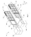
- FIGS. 10A-10C are schematic representations of the dual processing chambers 110 A, 110 B according to one embodiment.
- the dual processing chambers 110 A, 110 B include a plurality of microwave antennas 1010 disposed in a linear arrangement in the center of each processing chamber 110 A, 110 B.
- the antennas 1010 extend vertically from a top of the processing chamber to a bottom of the processing chamber.
- Each microwave antenna 1010 has a corresponding microwave power head 1012 at both the top and the bottom of the processing chamber that is coupled to the microwave antenna 1010 .
- the microwave power heads 1012 are staggered. The staggering may be due to space limitations. Power may be independently applied to the each end of the antenna 1010 through each power head 1012 .
- the microwave antennas 1010 may operate at a frequency within a range of 300 MHz and 300 GHz.
- Each of the processing chambers are arranged to be able to process two substrates, one on each side of the microwave antennas 1010 .
- the substrates are held in place within the processing chamber by a platen 1008 and a shadow frame 1004 .
- Gas introduction tubes may 1014 are disposed between adjacent microwave antennas 1010 .
- the gas introduction tubes 1014 extend vertically from the bottom to the top of the processing chamber parallel to the microwave antennas 1010 .
- the gas introduction tubes 1014 permit the introduction of processing gases, such as silicon precursors and nitrogen precursors. While not shown in FIGS. 10A-10C , the processing chambers 110 A, 110 B may be evacuated through a pumping port located behind the substrate carriers 1008 .
- FIGS. 11A and 11B are schematic representations of a processing chamber 1100 according to another embodiment.
- the processing chamber 1100 includes a plurality of plasma generators, such as microwave antennas, that extend vertically within the chamber body from a first end 1108 to a second end 1118 .
- the processing chamber 1100 includes a shadow frame 1104 on each side of the plasma generators 1102 for use in processing substrates.
- a shadow frame 1104 is disposed on opposite sides of the plurality of plasma generators 1102 so that there are two large area substrates may be processed within a single processing chamber 1100 and thus be exposed to the same processing environment either simultaneously or consecutively.
- Each plasma generator 1102 is coupled to a first waveguide 1110 at the first end 1108 thereof and to a second waveguide 1116 at the second end 1118 thereof.
- Each first waveguide 1110 is coupled to a first power source 1112 while each second waveguide is coupled to a second power source 1114 .
- the power sources 1112 , 1114 may be coupled to the waveguides 1110 , 1116 within an enclosure 1106 .
- the enclosures 1106 are staggered “T” shaped enclosures.
- the staggered “T” shaped enclosures may be necessary due to space limitations.
- adjacent waveguides 1110 , 1116 extend in opposite, parallel directions from the ends 1108 , 1118 to the respective power sources 1112 , 1114 .
- Gas introduction tubes may also be disposed within the processing chamber 1100 in the manner discussed above with regard to FIG. 10C .
- FIGS. 12A and 12B are schematic representations of a processing chamber 1200 according to another embodiment.
- the processing chamber 1200 includes a plurality of plasma generators, such as microwave antennas, that extend vertically within the chamber body from a first end 1208 to a second end 1218 .
- the processing chamber 1200 includes a shadow frame 1204 on each side of the plasma generators 1202 for use in processing substrates. As shown in FIG. 12B , a shadow frame 1204 is disposed on opposite sides of the plurality of plasma generators 1202 so that there are two large area substrates may be processed within a single processing chamber 1200 and thus be exposed to the same processing environment either simultaneously or consecutively.
- Each plasma generator 1202 is coupled to a first waveguide 1210 at the first end 1208 thereof and to a second waveguide 1216 at the second end 1218 thereof.
- Each first waveguide 1210 is coupled to a first power source 1212 while each second waveguide is coupled to a second power source 1214 .
- the power sources 1212 , 1214 may be coupled to the waveguides 1210 , 1216 within an enclosure 1206 .
- the enclosures 1206 all extend from the same side of the processing chamber 1200 .
- adjacent waveguides 1210 , 1216 extend in the same, parallel direction from the ends 1208 , 1218 to the respective power sources 1212 , 1214 .
- Gas introduction tubes may also be disposed within the processing chamber 1200 in the manner discussed above with regard to FIG. 10C .
- FIGS. 13A and 13B are schematic representations of a processing chamber 1300 according to another embodiment.
- the processing chamber 1300 includes a plurality of plasma generators, such as microwave antennas, that extend vertically within the chamber body from a first end 1308 to a second end 1318 .
- the processing chamber 1300 includes a shadow frame 1304 on each side of the plasma generators 1302 for use in processing substrates. As shown in FIG. 13B , a shadow frame 1304 is disposed on opposite sides of the plurality of plasma generators 1302 so that there are two large area substrates may be processed within a single processing chamber 1300 and thus be exposed to the same processing environment either simultaneously or consecutively.
- Each plasma generator 1302 is coupled to a first angled waveguide 1310 at the first end 1308 thereof and to a second angled waveguide 1316 at the second end 1318 thereof.
- Each first angled waveguide 1310 is coupled to a first power source 1312 while each second angled waveguide is coupled to a second power source 1314 .
- Enclosures 1306 are shown on top and bottom of the chamber 1300 by have been removed from the side of the chamber for clarity in viewing the waveguides 1310 , 1316 .
- the waveguides 1310 , 1316 extend along the top of the processing chamber 1300 and down along the side of the processing chamber 1300 to the respective power sources 1312 , 1314 .
- Gas introduction tubes may also be disposed within the processing chamber 1300 in the manner discussed above with regard to FIG. 10C .
- multiple substrates may be processed simultaneously. Processing multiple substrates simultaneously reduces the cost of manufacturing which may increase the manufacturer's profits.
Landscapes
- Chemical & Material Sciences (AREA)
- Engineering & Computer Science (AREA)
- Metallurgy (AREA)
- Chemical Kinetics & Catalysis (AREA)
- Materials Engineering (AREA)
- Mechanical Engineering (AREA)
- General Chemical & Material Sciences (AREA)
- Organic Chemistry (AREA)
- Physics & Mathematics (AREA)
- Plasma & Fusion (AREA)
- Analytical Chemistry (AREA)
- Chemical Vapour Deposition (AREA)
- Container, Conveyance, Adherence, Positioning, Of Wafer (AREA)
Abstract
Description
Claims (20)
Priority Applications (1)
| Application Number | Priority Date | Filing Date | Title |
|---|---|---|---|
| US13/098,255 US9324597B2 (en) | 2010-04-30 | 2011-04-29 | Vertical inline CVD system |
Applications Claiming Priority (4)
| Application Number | Priority Date | Filing Date | Title |
|---|---|---|---|
| US33029610P | 2010-04-30 | 2010-04-30 | |
| US35423010P | 2010-06-13 | 2010-06-13 | |
| US41653210P | 2010-11-23 | 2010-11-23 | |
| US13/098,255 US9324597B2 (en) | 2010-04-30 | 2011-04-29 | Vertical inline CVD system |
Publications (2)
| Publication Number | Publication Date |
|---|---|
| US20120031335A1 US20120031335A1 (en) | 2012-02-09 |
| US9324597B2 true US9324597B2 (en) | 2016-04-26 |
Family
ID=44862144
Family Applications (2)
| Application Number | Title | Priority Date | Filing Date |
|---|---|---|---|
| US13/098,253 Expired - Fee Related US9922854B2 (en) | 2010-04-30 | 2011-04-29 | Vertical inline CVD system |
| US13/098,255 Expired - Fee Related US9324597B2 (en) | 2010-04-30 | 2011-04-29 | Vertical inline CVD system |
Family Applications Before (1)
| Application Number | Title | Priority Date | Filing Date |
|---|---|---|---|
| US13/098,253 Expired - Fee Related US9922854B2 (en) | 2010-04-30 | 2011-04-29 | Vertical inline CVD system |
Country Status (6)
| Country | Link |
|---|---|
| US (2) | US9922854B2 (en) |
| JP (2) | JP5903429B2 (en) |
| KR (2) | KR101932578B1 (en) |
| CN (2) | CN102859655A (en) |
| TW (2) | TWI551718B (en) |
| WO (2) | WO2011137371A2 (en) |
Families Citing this family (392)
| Publication number | Priority date | Publication date | Assignee | Title |
|---|---|---|---|---|
| US10378106B2 (en) | 2008-11-14 | 2019-08-13 | Asm Ip Holding B.V. | Method of forming insulation film by modified PEALD |
| US9394608B2 (en) | 2009-04-06 | 2016-07-19 | Asm America, Inc. | Semiconductor processing reactor and components thereof |
| US8802201B2 (en) | 2009-08-14 | 2014-08-12 | Asm America, Inc. | Systems and methods for thin-film deposition of metal oxides using excited nitrogen-oxygen species |
| WO2011137371A2 (en) * | 2010-04-30 | 2011-11-03 | Applied Materials, Inc. | Vertical inline cvd system |
| US9312155B2 (en) | 2011-06-06 | 2016-04-12 | Asm Japan K.K. | High-throughput semiconductor-processing apparatus equipped with multiple dual-chamber modules |
| US9048518B2 (en) | 2011-06-21 | 2015-06-02 | Applied Materials, Inc. | Transmission line RF applicator for plasma chamber |
| US10364496B2 (en) | 2011-06-27 | 2019-07-30 | Asm Ip Holding B.V. | Dual section module having shared and unshared mass flow controllers |
| US10854498B2 (en) | 2011-07-15 | 2020-12-01 | Asm Ip Holding B.V. | Wafer-supporting device and method for producing same |
| US20130023129A1 (en) | 2011-07-20 | 2013-01-24 | Asm America, Inc. | Pressure transmitter for a semiconductor processing environment |
| US9644268B2 (en) * | 2011-08-31 | 2017-05-09 | Alta Devices, Inc. | Thermal bridge for chemical vapor deposition reactors |
| US9017481B1 (en) | 2011-10-28 | 2015-04-28 | Asm America, Inc. | Process feed management for semiconductor substrate processing |
| KR102168063B1 (en) | 2012-01-27 | 2020-10-20 | 어플라이드 머티어리얼스, 인코포레이티드 | Segmented antenna assembly |
| WO2013122954A1 (en) * | 2012-02-13 | 2013-08-22 | Applied Materials, Inc. | Linear pecvd apparatus |
| US9659799B2 (en) | 2012-08-28 | 2017-05-23 | Asm Ip Holding B.V. | Systems and methods for dynamic semiconductor process scheduling |
| US9021985B2 (en) | 2012-09-12 | 2015-05-05 | Asm Ip Holdings B.V. | Process gas management for an inductively-coupled plasma deposition reactor |
| US10714315B2 (en) | 2012-10-12 | 2020-07-14 | Asm Ip Holdings B.V. | Semiconductor reaction chamber showerhead |
| US20160376700A1 (en) | 2013-02-01 | 2016-12-29 | Asm Ip Holding B.V. | System for treatment of deposition reactor |
| US9589770B2 (en) | 2013-03-08 | 2017-03-07 | Asm Ip Holding B.V. | Method and systems for in-situ formation of intermediate reactive species |
| US9484191B2 (en) | 2013-03-08 | 2016-11-01 | Asm Ip Holding B.V. | Pulsed remote plasma method and system |
| US9240412B2 (en) | 2013-09-27 | 2016-01-19 | Asm Ip Holding B.V. | Semiconductor structure and device and methods of forming same using selective epitaxial process |
| TWI582028B (en) * | 2014-01-03 | 2017-05-11 | 緯創資通股份有限公司 | Feeder system and material guiding carrier thereof |
| US10683571B2 (en) | 2014-02-25 | 2020-06-16 | Asm Ip Holding B.V. | Gas supply manifold and method of supplying gases to chamber using same |
| US10167557B2 (en) | 2014-03-18 | 2019-01-01 | Asm Ip Holding B.V. | Gas distribution system, reactor including the system, and methods of using the same |
| US11015245B2 (en) | 2014-03-19 | 2021-05-25 | Asm Ip Holding B.V. | Gas-phase reactor and system having exhaust plenum and components thereof |
| US10096509B2 (en) * | 2014-05-09 | 2018-10-09 | Applied Materials, Inc. | Substrate carrier system with protective covering |
| US10153191B2 (en) * | 2014-05-09 | 2018-12-11 | Applied Materials, Inc. | Substrate carrier system and method for using the same |
| US10858737B2 (en) | 2014-07-28 | 2020-12-08 | Asm Ip Holding B.V. | Showerhead assembly and components thereof |
| CN104195629A (en) * | 2014-08-20 | 2014-12-10 | 中国科学院半导体研究所 | Tower-type multichip epitaxial growth device |
| US9890456B2 (en) | 2014-08-21 | 2018-02-13 | Asm Ip Holding B.V. | Method and system for in situ formation of gas-phase compounds |
| US9657845B2 (en) | 2014-10-07 | 2017-05-23 | Asm Ip Holding B.V. | Variable conductance gas distribution apparatus and method |
| US10941490B2 (en) | 2014-10-07 | 2021-03-09 | Asm Ip Holding B.V. | Multiple temperature range susceptor, assembly, reactor and system including the susceptor, and methods of using the same |
| KR102263121B1 (en) | 2014-12-22 | 2021-06-09 | 에이에스엠 아이피 홀딩 비.브이. | Semiconductor device and manufacuring method thereof |
| US10529542B2 (en) | 2015-03-11 | 2020-01-07 | Asm Ip Holdings B.V. | Cross-flow reactor and method |
| US10276355B2 (en) | 2015-03-12 | 2019-04-30 | Asm Ip Holding B.V. | Multi-zone reactor, system including the reactor, and method of using the same |
| US10458018B2 (en) | 2015-06-26 | 2019-10-29 | Asm Ip Holding B.V. | Structures including metal carbide material, devices including the structures, and methods of forming same |
| US10600673B2 (en) * | 2015-07-07 | 2020-03-24 | Asm Ip Holding B.V. | Magnetic susceptor to baseplate seal |
| US10083836B2 (en) | 2015-07-24 | 2018-09-25 | Asm Ip Holding B.V. | Formation of boron-doped titanium metal films with high work function |
| KR102400863B1 (en) * | 2015-07-27 | 2022-05-24 | 삼성디스플레이 주식회사 | Apparatus of treating plasma and method of treating plasma subatrate using the same |
| US10039219B1 (en) | 2015-09-28 | 2018-07-31 | Western Digital Technologies, Inc. | Method and devices for picking and placing workpieces into devices under manufacture using dual robots |
| US9960072B2 (en) | 2015-09-29 | 2018-05-01 | Asm Ip Holding B.V. | Variable adjustment for precise matching of multiple chamber cavity housings |
| US10211308B2 (en) | 2015-10-21 | 2019-02-19 | Asm Ip Holding B.V. | NbMC layers |
| US10322384B2 (en) | 2015-11-09 | 2019-06-18 | Asm Ip Holding B.V. | Counter flow mixer for process chamber |
| US11139308B2 (en) | 2015-12-29 | 2021-10-05 | Asm Ip Holding B.V. | Atomic layer deposition of III-V compounds to form V-NAND devices |
| US10468251B2 (en) | 2016-02-19 | 2019-11-05 | Asm Ip Holding B.V. | Method for forming spacers using silicon nitride film for spacer-defined multiple patterning |
| US10529554B2 (en) | 2016-02-19 | 2020-01-07 | Asm Ip Holding B.V. | Method for forming silicon nitride film selectively on sidewalls or flat surfaces of trenches |
| US10501866B2 (en) | 2016-03-09 | 2019-12-10 | Asm Ip Holding B.V. | Gas distribution apparatus for improved film uniformity in an epitaxial system |
| US10343920B2 (en) | 2016-03-18 | 2019-07-09 | Asm Ip Holding B.V. | Aligned carbon nanotubes |
| US9892913B2 (en) | 2016-03-24 | 2018-02-13 | Asm Ip Holding B.V. | Radial and thickness control via biased multi-port injection settings |
| US10190213B2 (en) | 2016-04-21 | 2019-01-29 | Asm Ip Holding B.V. | Deposition of metal borides |
| US10865475B2 (en) | 2016-04-21 | 2020-12-15 | Asm Ip Holding B.V. | Deposition of metal borides and silicides |
| US10367080B2 (en) | 2016-05-02 | 2019-07-30 | Asm Ip Holding B.V. | Method of forming a germanium oxynitride film |
| US10032628B2 (en) | 2016-05-02 | 2018-07-24 | Asm Ip Holding B.V. | Source/drain performance through conformal solid state doping |
| KR102592471B1 (en) | 2016-05-17 | 2023-10-20 | 에이에스엠 아이피 홀딩 비.브이. | Method of forming metal interconnection and method of fabricating semiconductor device using the same |
| US11453943B2 (en) | 2016-05-25 | 2022-09-27 | Asm Ip Holding B.V. | Method for forming carbon-containing silicon/metal oxide or nitride film by ALD using silicon precursor and hydrocarbon precursor |
| US10388509B2 (en) | 2016-06-28 | 2019-08-20 | Asm Ip Holding B.V. | Formation of epitaxial layers via dislocation filtering |
| US10612137B2 (en) | 2016-07-08 | 2020-04-07 | Asm Ip Holdings B.V. | Organic reactants for atomic layer deposition |
| US9859151B1 (en) | 2016-07-08 | 2018-01-02 | Asm Ip Holding B.V. | Selective film deposition method to form air gaps |
| US10714385B2 (en) | 2016-07-19 | 2020-07-14 | Asm Ip Holding B.V. | Selective deposition of tungsten |
| US10381226B2 (en) | 2016-07-27 | 2019-08-13 | Asm Ip Holding B.V. | Method of processing substrate |
| US9887082B1 (en) | 2016-07-28 | 2018-02-06 | Asm Ip Holding B.V. | Method and apparatus for filling a gap |
| KR102532607B1 (en) | 2016-07-28 | 2023-05-15 | 에이에스엠 아이피 홀딩 비.브이. | Substrate processing apparatus and method of operating the same |
| US9812320B1 (en) | 2016-07-28 | 2017-11-07 | Asm Ip Holding B.V. | Method and apparatus for filling a gap |
| US10395919B2 (en) | 2016-07-28 | 2019-08-27 | Asm Ip Holding B.V. | Method and apparatus for filling a gap |
| TWI588929B (en) * | 2016-08-01 | 2017-06-21 | 矽品精密工業股份有限公司 | Carrying device and its method of operation |
| US10410943B2 (en) | 2016-10-13 | 2019-09-10 | Asm Ip Holding B.V. | Method for passivating a surface of a semiconductor and related systems |
| US10643826B2 (en) | 2016-10-26 | 2020-05-05 | Asm Ip Holdings B.V. | Methods for thermally calibrating reaction chambers |
| US11532757B2 (en) | 2016-10-27 | 2022-12-20 | Asm Ip Holding B.V. | Deposition of charge trapping layers |
| US10435790B2 (en) | 2016-11-01 | 2019-10-08 | Asm Ip Holding B.V. | Method of subatmospheric plasma-enhanced ALD using capacitively coupled electrodes with narrow gap |
| US10714350B2 (en) | 2016-11-01 | 2020-07-14 | ASM IP Holdings, B.V. | Methods for forming a transition metal niobium nitride film on a substrate by atomic layer deposition and related semiconductor device structures |
| US10229833B2 (en) | 2016-11-01 | 2019-03-12 | Asm Ip Holding B.V. | Methods for forming a transition metal nitride film on a substrate by atomic layer deposition and related semiconductor device structures |
| US10643904B2 (en) | 2016-11-01 | 2020-05-05 | Asm Ip Holdings B.V. | Methods for forming a semiconductor device and related semiconductor device structures |
| US10134757B2 (en) | 2016-11-07 | 2018-11-20 | Asm Ip Holding B.V. | Method of processing a substrate and a device manufactured by using the method |
| KR102546317B1 (en) | 2016-11-15 | 2023-06-21 | 에이에스엠 아이피 홀딩 비.브이. | Gas supply unit and substrate processing apparatus including the same |
| US10340135B2 (en) | 2016-11-28 | 2019-07-02 | Asm Ip Holding B.V. | Method of topologically restricted plasma-enhanced cyclic deposition of silicon or metal nitride |
| KR102762543B1 (en) | 2016-12-14 | 2025-02-05 | 에이에스엠 아이피 홀딩 비.브이. | Substrate processing apparatus |
| US11581186B2 (en) | 2016-12-15 | 2023-02-14 | Asm Ip Holding B.V. | Sequential infiltration synthesis apparatus |
| US11447861B2 (en) | 2016-12-15 | 2022-09-20 | Asm Ip Holding B.V. | Sequential infiltration synthesis apparatus and a method of forming a patterned structure |
| KR102700194B1 (en) | 2016-12-19 | 2024-08-28 | 에이에스엠 아이피 홀딩 비.브이. | Substrate processing apparatus |
| US10269558B2 (en) | 2016-12-22 | 2019-04-23 | Asm Ip Holding B.V. | Method of forming a structure on a substrate |
| US10867788B2 (en) | 2016-12-28 | 2020-12-15 | Asm Ip Holding B.V. | Method of forming a structure on a substrate |
| US11390950B2 (en) | 2017-01-10 | 2022-07-19 | Asm Ip Holding B.V. | Reactor system and method to reduce residue buildup during a film deposition process |
| US10655221B2 (en) | 2017-02-09 | 2020-05-19 | Asm Ip Holding B.V. | Method for depositing oxide film by thermal ALD and PEALD |
| US10468261B2 (en) | 2017-02-15 | 2019-11-05 | Asm Ip Holding B.V. | Methods for forming a metallic film on a substrate by cyclical deposition and related semiconductor device structures |
| US10283353B2 (en) | 2017-03-29 | 2019-05-07 | Asm Ip Holding B.V. | Method of reforming insulating film deposited on substrate with recess pattern |
| US10529563B2 (en) | 2017-03-29 | 2020-01-07 | Asm Ip Holdings B.V. | Method for forming doped metal oxide films on a substrate by cyclical deposition and related semiconductor device structures |
| KR102457289B1 (en) | 2017-04-25 | 2022-10-21 | 에이에스엠 아이피 홀딩 비.브이. | Method for depositing a thin film and manufacturing a semiconductor device |
| US10770286B2 (en) | 2017-05-08 | 2020-09-08 | Asm Ip Holdings B.V. | Methods for selectively forming a silicon nitride film on a substrate and related semiconductor device structures |
| US10892156B2 (en) | 2017-05-08 | 2021-01-12 | Asm Ip Holding B.V. | Methods for forming a silicon nitride film on a substrate and related semiconductor device structures |
| US10446393B2 (en) | 2017-05-08 | 2019-10-15 | Asm Ip Holding B.V. | Methods for forming silicon-containing epitaxial layers and related semiconductor device structures |
| US10504742B2 (en) | 2017-05-31 | 2019-12-10 | Asm Ip Holding B.V. | Method of atomic layer etching using hydrogen plasma |
| US10886123B2 (en) | 2017-06-02 | 2021-01-05 | Asm Ip Holding B.V. | Methods for forming low temperature semiconductor layers and related semiconductor device structures |
| US12040200B2 (en) | 2017-06-20 | 2024-07-16 | Asm Ip Holding B.V. | Semiconductor processing apparatus and methods for calibrating a semiconductor processing apparatus |
| US11306395B2 (en) | 2017-06-28 | 2022-04-19 | Asm Ip Holding B.V. | Methods for depositing a transition metal nitride film on a substrate by atomic layer deposition and related deposition apparatus |
| US10685834B2 (en) | 2017-07-05 | 2020-06-16 | Asm Ip Holdings B.V. | Methods for forming a silicon germanium tin layer and related semiconductor device structures |
| KR20190009245A (en) | 2017-07-18 | 2019-01-28 | 에이에스엠 아이피 홀딩 비.브이. | Methods for forming a semiconductor device structure and related semiconductor device structures |
| US11018002B2 (en) | 2017-07-19 | 2021-05-25 | Asm Ip Holding B.V. | Method for selectively depositing a Group IV semiconductor and related semiconductor device structures |
| US11374112B2 (en) | 2017-07-19 | 2022-06-28 | Asm Ip Holding B.V. | Method for depositing a group IV semiconductor and related semiconductor device structures |
| US10541333B2 (en) | 2017-07-19 | 2020-01-21 | Asm Ip Holding B.V. | Method for depositing a group IV semiconductor and related semiconductor device structures |
| CN109563609B (en) * | 2017-07-24 | 2021-04-13 | 应用材料公司 | Apparatus and system for processing a substrate in a vacuum chamber and method of transporting a carrier in a vacuum chamber |
| US10590535B2 (en) | 2017-07-26 | 2020-03-17 | Asm Ip Holdings B.V. | Chemical treatment, deposition and/or infiltration apparatus and method for using the same |
| US10312055B2 (en) | 2017-07-26 | 2019-06-04 | Asm Ip Holding B.V. | Method of depositing film by PEALD using negative bias |
| US10605530B2 (en) | 2017-07-26 | 2020-03-31 | Asm Ip Holding B.V. | Assembly of a liner and a flange for a vertical furnace as well as the liner and the vertical furnace |
| TWI815813B (en) | 2017-08-04 | 2023-09-21 | 荷蘭商Asm智慧財產控股公司 | Showerhead assembly for distributing a gas within a reaction chamber |
| US10692741B2 (en) | 2017-08-08 | 2020-06-23 | Asm Ip Holdings B.V. | Radiation shield |
| US10770336B2 (en) | 2017-08-08 | 2020-09-08 | Asm Ip Holding B.V. | Substrate lift mechanism and reactor including same |
| US11769682B2 (en) | 2017-08-09 | 2023-09-26 | Asm Ip Holding B.V. | Storage apparatus for storing cassettes for substrates and processing apparatus equipped therewith |
| US10249524B2 (en) | 2017-08-09 | 2019-04-02 | Asm Ip Holding B.V. | Cassette holder assembly for a substrate cassette and holding member for use in such assembly |
| US11139191B2 (en) | 2017-08-09 | 2021-10-05 | Asm Ip Holding B.V. | Storage apparatus for storing cassettes for substrates and processing apparatus equipped therewith |
| US10236177B1 (en) | 2017-08-22 | 2019-03-19 | ASM IP Holding B.V.. | Methods for depositing a doped germanium tin semiconductor and related semiconductor device structures |
| USD900036S1 (en) | 2017-08-24 | 2020-10-27 | Asm Ip Holding B.V. | Heater electrical connector and adapter |
| US11830730B2 (en) | 2017-08-29 | 2023-11-28 | Asm Ip Holding B.V. | Layer forming method and apparatus |
| US11056344B2 (en) | 2017-08-30 | 2021-07-06 | Asm Ip Holding B.V. | Layer forming method |
| US11295980B2 (en) | 2017-08-30 | 2022-04-05 | Asm Ip Holding B.V. | Methods for depositing a molybdenum metal film over a dielectric surface of a substrate by a cyclical deposition process and related semiconductor device structures |
| KR102491945B1 (en) | 2017-08-30 | 2023-01-26 | 에이에스엠 아이피 홀딩 비.브이. | Substrate processing apparatus |
| KR102401446B1 (en) | 2017-08-31 | 2022-05-24 | 에이에스엠 아이피 홀딩 비.브이. | Substrate processing apparatus |
| US10607895B2 (en) | 2017-09-18 | 2020-03-31 | Asm Ip Holdings B.V. | Method for forming a semiconductor device structure comprising a gate fill metal |
| KR102630301B1 (en) | 2017-09-21 | 2024-01-29 | 에이에스엠 아이피 홀딩 비.브이. | Method of sequential infiltration synthesis treatment of infiltrateable material and structures and devices formed using same |
| US10844484B2 (en) | 2017-09-22 | 2020-11-24 | Asm Ip Holding B.V. | Apparatus for dispensing a vapor phase reactant to a reaction chamber and related methods |
| US10658205B2 (en) | 2017-09-28 | 2020-05-19 | Asm Ip Holdings B.V. | Chemical dispensing apparatus and methods for dispensing a chemical to a reaction chamber |
| US10403504B2 (en) | 2017-10-05 | 2019-09-03 | Asm Ip Holding B.V. | Method for selectively depositing a metallic film on a substrate |
| US10319588B2 (en) | 2017-10-10 | 2019-06-11 | Asm Ip Holding B.V. | Method for depositing a metal chalcogenide on a substrate by cyclical deposition |
| US10861692B2 (en) | 2017-10-26 | 2020-12-08 | Taiwan Semiconductor Manufacturing Co., Ltd. | Substrate carrier deterioration detection and repair |
| US10923344B2 (en) | 2017-10-30 | 2021-02-16 | Asm Ip Holding B.V. | Methods for forming a semiconductor structure and related semiconductor structures |
| KR102443047B1 (en) | 2017-11-16 | 2022-09-14 | 에이에스엠 아이피 홀딩 비.브이. | Substrate processing apparatus method and apparatus manufactured thereby |
| US10910262B2 (en) | 2017-11-16 | 2021-02-02 | Asm Ip Holding B.V. | Method of selectively depositing a capping layer structure on a semiconductor device structure |
| US11022879B2 (en) | 2017-11-24 | 2021-06-01 | Asm Ip Holding B.V. | Method of forming an enhanced unexposed photoresist layer |
| TWI791689B (en) | 2017-11-27 | 2023-02-11 | 荷蘭商Asm智慧財產控股私人有限公司 | Apparatus including a clean mini environment |
| JP7214724B2 (en) | 2017-11-27 | 2023-01-30 | エーエスエム アイピー ホールディング ビー.ブイ. | Storage device for storing wafer cassettes used in batch furnaces |
| US10290508B1 (en) | 2017-12-05 | 2019-05-14 | Asm Ip Holding B.V. | Method for forming vertical spacers for spacer-defined patterning |
| CN108048818A (en) * | 2017-12-18 | 2018-05-18 | 德淮半导体有限公司 | Chemical vapor deposition unit and its application method |
| US10872771B2 (en) | 2018-01-16 | 2020-12-22 | Asm Ip Holding B. V. | Method for depositing a material film on a substrate within a reaction chamber by a cyclical deposition process and related device structures |
| TWI799494B (en) | 2018-01-19 | 2023-04-21 | 荷蘭商Asm 智慧財產控股公司 | Deposition method |
| KR102695659B1 (en) | 2018-01-19 | 2024-08-14 | 에이에스엠 아이피 홀딩 비.브이. | Method for depositing a gap filling layer by plasma assisted deposition |
| USD903477S1 (en) | 2018-01-24 | 2020-12-01 | Asm Ip Holdings B.V. | Metal clamp |
| US11018047B2 (en) | 2018-01-25 | 2021-05-25 | Asm Ip Holding B.V. | Hybrid lift pin |
| US10535516B2 (en) | 2018-02-01 | 2020-01-14 | Asm Ip Holdings B.V. | Method for depositing a semiconductor structure on a surface of a substrate and related semiconductor structures |
| USD880437S1 (en) | 2018-02-01 | 2020-04-07 | Asm Ip Holding B.V. | Gas supply plate for semiconductor manufacturing apparatus |
| US11081345B2 (en) | 2018-02-06 | 2021-08-03 | Asm Ip Holding B.V. | Method of post-deposition treatment for silicon oxide film |
| US10896820B2 (en) | 2018-02-14 | 2021-01-19 | Asm Ip Holding B.V. | Method for depositing a ruthenium-containing film on a substrate by a cyclical deposition process |
| US11685991B2 (en) | 2018-02-14 | 2023-06-27 | Asm Ip Holding B.V. | Method for depositing a ruthenium-containing film on a substrate by a cyclical deposition process |
| US10731249B2 (en) | 2018-02-15 | 2020-08-04 | Asm Ip Holding B.V. | Method of forming a transition metal containing film on a substrate by a cyclical deposition process, a method for supplying a transition metal halide compound to a reaction chamber, and related vapor deposition apparatus |
| US10658181B2 (en) | 2018-02-20 | 2020-05-19 | Asm Ip Holding B.V. | Method of spacer-defined direct patterning in semiconductor fabrication |
| KR102636427B1 (en) | 2018-02-20 | 2024-02-13 | 에이에스엠 아이피 홀딩 비.브이. | Substrate processing method and apparatus |
| US10975470B2 (en) | 2018-02-23 | 2021-04-13 | Asm Ip Holding B.V. | Apparatus for detecting or monitoring for a chemical precursor in a high temperature environment |
| US12224156B2 (en) | 2018-03-01 | 2025-02-11 | Applied Materials, Inc. | Microwave plasma source for spatial plasma enhanced atomic layer deposition (PE-ALD) processing tool |
| US11473195B2 (en) | 2018-03-01 | 2022-10-18 | Asm Ip Holding B.V. | Semiconductor processing apparatus and a method for processing a substrate |
| TWI758589B (en) | 2018-03-01 | 2022-03-21 | 美商應用材料股份有限公司 | Plasma source assemblies and methods of providing plasma |
| US11629406B2 (en) | 2018-03-09 | 2023-04-18 | Asm Ip Holding B.V. | Semiconductor processing apparatus comprising one or more pyrometers for measuring a temperature of a substrate during transfer of the substrate |
| US11114283B2 (en) | 2018-03-16 | 2021-09-07 | Asm Ip Holding B.V. | Reactor, system including the reactor, and methods of manufacturing and using same |
| KR102646467B1 (en) | 2018-03-27 | 2024-03-11 | 에이에스엠 아이피 홀딩 비.브이. | Method of forming an electrode on a substrate and a semiconductor device structure including an electrode |
| US10510536B2 (en) | 2018-03-29 | 2019-12-17 | Asm Ip Holding B.V. | Method of depositing a co-doped polysilicon film on a surface of a substrate within a reaction chamber |
| US11088002B2 (en) | 2018-03-29 | 2021-08-10 | Asm Ip Holding B.V. | Substrate rack and a substrate processing system and method |
| US11230766B2 (en) | 2018-03-29 | 2022-01-25 | Asm Ip Holding B.V. | Substrate processing apparatus and method |
| KR102501472B1 (en) | 2018-03-30 | 2023-02-20 | 에이에스엠 아이피 홀딩 비.브이. | Substrate processing method |
| KR102600229B1 (en) | 2018-04-09 | 2023-11-10 | 에이에스엠 아이피 홀딩 비.브이. | Substrate supporting device, substrate processing apparatus including the same and substrate processing method |
| TWI843623B (en) | 2018-05-08 | 2024-05-21 | 荷蘭商Asm Ip私人控股有限公司 | Methods for depositing an oxide film on a substrate by a cyclical deposition process and related device structures |
| US12025484B2 (en) | 2018-05-08 | 2024-07-02 | Asm Ip Holding B.V. | Thin film forming method |
| US12272527B2 (en) | 2018-05-09 | 2025-04-08 | Asm Ip Holding B.V. | Apparatus for use with hydrogen radicals and method of using same |
| KR20190129718A (en) | 2018-05-11 | 2019-11-20 | 에이에스엠 아이피 홀딩 비.브이. | Methods for forming a doped metal carbide film on a substrate and related semiconductor device structures |
| KR102596988B1 (en) | 2018-05-28 | 2023-10-31 | 에이에스엠 아이피 홀딩 비.브이. | Method of processing a substrate and a device manufactured by the same |
| TWI840362B (en) | 2018-06-04 | 2024-05-01 | 荷蘭商Asm Ip私人控股有限公司 | Wafer handling chamber with moisture reduction |
| US11718913B2 (en) | 2018-06-04 | 2023-08-08 | Asm Ip Holding B.V. | Gas distribution system and reactor system including same |
| US11286562B2 (en) | 2018-06-08 | 2022-03-29 | Asm Ip Holding B.V. | Gas-phase chemical reactor and method of using same |
| KR102568797B1 (en) | 2018-06-21 | 2023-08-21 | 에이에스엠 아이피 홀딩 비.브이. | Substrate processing system |
| US10797133B2 (en) | 2018-06-21 | 2020-10-06 | Asm Ip Holding B.V. | Method for depositing a phosphorus doped silicon arsenide film and related semiconductor device structures |
| TWI871083B (en) | 2018-06-27 | 2025-01-21 | 荷蘭商Asm Ip私人控股有限公司 | Cyclic deposition processes for forming metal-containing material |
| US11499222B2 (en) | 2018-06-27 | 2022-11-15 | Asm Ip Holding B.V. | Cyclic deposition methods for forming metal-containing material and films and structures including the metal-containing material |
| US10612136B2 (en) | 2018-06-29 | 2020-04-07 | ASM IP Holding, B.V. | Temperature-controlled flange and reactor system including same |
| KR102686758B1 (en) | 2018-06-29 | 2024-07-18 | 에이에스엠 아이피 홀딩 비.브이. | Method for depositing a thin film and manufacturing a semiconductor device |
| US10755922B2 (en) | 2018-07-03 | 2020-08-25 | Asm Ip Holding B.V. | Method for depositing silicon-free carbon-containing film as gap-fill layer by pulse plasma-assisted deposition |
| US10388513B1 (en) | 2018-07-03 | 2019-08-20 | Asm Ip Holding B.V. | Method for depositing silicon-free carbon-containing film as gap-fill layer by pulse plasma-assisted deposition |
| US10767789B2 (en) | 2018-07-16 | 2020-09-08 | Asm Ip Holding B.V. | Diaphragm valves, valve components, and methods for forming valve components |
| US10483099B1 (en) | 2018-07-26 | 2019-11-19 | Asm Ip Holding B.V. | Method for forming thermally stable organosilicon polymer film |
| US11053591B2 (en) | 2018-08-06 | 2021-07-06 | Asm Ip Holding B.V. | Multi-port gas injection system and reactor system including same |
| US10883175B2 (en) | 2018-08-09 | 2021-01-05 | Asm Ip Holding B.V. | Vertical furnace for processing substrates and a liner for use therein |
| US10829852B2 (en) | 2018-08-16 | 2020-11-10 | Asm Ip Holding B.V. | Gas distribution device for a wafer processing apparatus |
| US11430674B2 (en) | 2018-08-22 | 2022-08-30 | Asm Ip Holding B.V. | Sensor array, apparatus for dispensing a vapor phase reactant to a reaction chamber and related methods |
| KR102707956B1 (en) | 2018-09-11 | 2024-09-19 | 에이에스엠 아이피 홀딩 비.브이. | Method for deposition of a thin film |
| US11024523B2 (en) | 2018-09-11 | 2021-06-01 | Asm Ip Holding B.V. | Substrate processing apparatus and method |
| US11049751B2 (en) | 2018-09-14 | 2021-06-29 | Asm Ip Holding B.V. | Cassette supply system to store and handle cassettes and processing apparatus equipped therewith |
| CN110970344B (en) | 2018-10-01 | 2024-10-25 | Asmip控股有限公司 | Substrate holding device, system including the same and method of using the same |
| US11232963B2 (en) | 2018-10-03 | 2022-01-25 | Asm Ip Holding B.V. | Substrate processing apparatus and method |
| JP7231721B2 (en) | 2018-10-04 | 2023-03-01 | アプライド マテリアルズ インコーポレイテッド | Conveyor system |
| KR102592699B1 (en) | 2018-10-08 | 2023-10-23 | 에이에스엠 아이피 홀딩 비.브이. | Substrate support unit and apparatuses for depositing thin film and processing the substrate including the same |
| US10847365B2 (en) | 2018-10-11 | 2020-11-24 | Asm Ip Holding B.V. | Method of forming conformal silicon carbide film by cyclic CVD |
| US10811256B2 (en) | 2018-10-16 | 2020-10-20 | Asm Ip Holding B.V. | Method for etching a carbon-containing feature |
| KR102605121B1 (en) | 2018-10-19 | 2023-11-23 | 에이에스엠 아이피 홀딩 비.브이. | Substrate processing apparatus and substrate processing method |
| KR102546322B1 (en) | 2018-10-19 | 2023-06-21 | 에이에스엠 아이피 홀딩 비.브이. | Substrate processing apparatus and substrate processing method |
| USD948463S1 (en) | 2018-10-24 | 2022-04-12 | Asm Ip Holding B.V. | Susceptor for semiconductor substrate supporting apparatus |
| US10381219B1 (en) | 2018-10-25 | 2019-08-13 | Asm Ip Holding B.V. | Methods for forming a silicon nitride film |
| US12378665B2 (en) | 2018-10-26 | 2025-08-05 | Asm Ip Holding B.V. | High temperature coatings for a preclean and etch apparatus and related methods |
| US11145517B2 (en) * | 2018-10-29 | 2021-10-12 | Taiwan Semiconductor Manufacturing Co., Ltd. | Gas curtain for semiconductor manufacturing system |
| US11087997B2 (en) | 2018-10-31 | 2021-08-10 | Asm Ip Holding B.V. | Substrate processing apparatus for processing substrates |
| KR102748291B1 (en) | 2018-11-02 | 2024-12-31 | 에이에스엠 아이피 홀딩 비.브이. | Substrate support unit and substrate processing apparatus including the same |
| US11572620B2 (en) | 2018-11-06 | 2023-02-07 | Asm Ip Holding B.V. | Methods for selectively depositing an amorphous silicon film on a substrate |
| US11031242B2 (en) | 2018-11-07 | 2021-06-08 | Asm Ip Holding B.V. | Methods for depositing a boron doped silicon germanium film |
| US10847366B2 (en) | 2018-11-16 | 2020-11-24 | Asm Ip Holding B.V. | Methods for depositing a transition metal chalcogenide film on a substrate by a cyclical deposition process |
| US10818758B2 (en) | 2018-11-16 | 2020-10-27 | Asm Ip Holding B.V. | Methods for forming a metal silicate film on a substrate in a reaction chamber and related semiconductor device structures |
| US10559458B1 (en) | 2018-11-26 | 2020-02-11 | Asm Ip Holding B.V. | Method of forming oxynitride film |
| US12040199B2 (en) | 2018-11-28 | 2024-07-16 | Asm Ip Holding B.V. | Substrate processing apparatus for processing substrates |
| US11217444B2 (en) | 2018-11-30 | 2022-01-04 | Asm Ip Holding B.V. | Method for forming an ultraviolet radiation responsive metal oxide-containing film |
| KR102636428B1 (en) | 2018-12-04 | 2024-02-13 | 에이에스엠 아이피 홀딩 비.브이. | A method for cleaning a substrate processing apparatus |
| US11158513B2 (en) | 2018-12-13 | 2021-10-26 | Asm Ip Holding B.V. | Methods for forming a rhenium-containing film on a substrate by a cyclical deposition process and related semiconductor device structures |
| JP7504584B2 (en) | 2018-12-14 | 2024-06-24 | エーエスエム・アイピー・ホールディング・ベー・フェー | Method and system for forming device structures using selective deposition of gallium nitride - Patents.com |
| US11694913B2 (en) * | 2018-12-18 | 2023-07-04 | Intevac, Inc. | Hybrid system architecture for thin film deposition |
| TWI866480B (en) | 2019-01-17 | 2024-12-11 | 荷蘭商Asm Ip 私人控股有限公司 | Methods of forming a transition metal containing film on a substrate by a cyclical deposition process |
| KR102727227B1 (en) | 2019-01-22 | 2024-11-07 | 에이에스엠 아이피 홀딩 비.브이. | Semiconductor processing device |
| CN111524788B (en) | 2019-02-01 | 2023-11-24 | Asm Ip私人控股有限公司 | Method for forming topologically selective films of silicon oxide |
| TWI873122B (en) | 2019-02-20 | 2025-02-21 | 荷蘭商Asm Ip私人控股有限公司 | Method of filling a recess formed within a surface of a substrate, semiconductor structure formed according to the method, and semiconductor processing apparatus |
| KR102626263B1 (en) | 2019-02-20 | 2024-01-16 | 에이에스엠 아이피 홀딩 비.브이. | Cyclical deposition method including treatment step and apparatus for same |
| KR20200102357A (en) | 2019-02-20 | 2020-08-31 | 에이에스엠 아이피 홀딩 비.브이. | Apparatus and methods for plug fill deposition in 3-d nand applications |
| TWI845607B (en) | 2019-02-20 | 2024-06-21 | 荷蘭商Asm Ip私人控股有限公司 | Cyclical deposition method and apparatus for filling a recess formed within a substrate surface |
| TWI842826B (en) | 2019-02-22 | 2024-05-21 | 荷蘭商Asm Ip私人控股有限公司 | Substrate processing apparatus and method for processing substrate |
| JP6855147B2 (en) * | 2019-02-28 | 2021-04-07 | 東芝三菱電機産業システム株式会社 | Film deposition equipment |
| KR102858005B1 (en) | 2019-03-08 | 2025-09-09 | 에이에스엠 아이피 홀딩 비.브이. | Method for Selective Deposition of Silicon Nitride Layer and Structure Including Selectively-Deposited Silicon Nitride Layer |
| KR102782593B1 (en) | 2019-03-08 | 2025-03-14 | 에이에스엠 아이피 홀딩 비.브이. | Structure Including SiOC Layer and Method of Forming Same |
| KR102762833B1 (en) | 2019-03-08 | 2025-02-04 | 에이에스엠 아이피 홀딩 비.브이. | STRUCTURE INCLUDING SiOCN LAYER AND METHOD OF FORMING SAME |
| JP2020167398A (en) | 2019-03-28 | 2020-10-08 | エーエスエム・アイピー・ホールディング・ベー・フェー | Door openers and substrate processing equipment provided with door openers |
| KR102809999B1 (en) | 2019-04-01 | 2025-05-19 | 에이에스엠 아이피 홀딩 비.브이. | Method of manufacturing semiconductor device |
| KR102897355B1 (en) | 2019-04-19 | 2025-12-08 | 에이에스엠 아이피 홀딩 비.브이. | Layer forming method and apparatus |
| KR20200125453A (en) | 2019-04-24 | 2020-11-04 | 에이에스엠 아이피 홀딩 비.브이. | Gas-phase reactor system and method of using same |
| KR102929471B1 (en) | 2019-05-07 | 2026-02-20 | 에이에스엠 아이피 홀딩 비.브이. | Chemical source vessel with dip tube |
| KR102869364B1 (en) | 2019-05-07 | 2025-10-10 | 에이에스엠 아이피 홀딩 비.브이. | Method for Reforming Amorphous Carbon Polymer Film |
| KR102929472B1 (en) | 2019-05-10 | 2026-02-20 | 에이에스엠 아이피 홀딩 비.브이. | Method of depositing material onto a surface and structure formed according to the method |
| JP7612342B2 (en) | 2019-05-16 | 2025-01-14 | エーエスエム・アイピー・ホールディング・ベー・フェー | Wafer boat handling apparatus, vertical batch furnace and method |
| JP7598201B2 (en) | 2019-05-16 | 2024-12-11 | エーエスエム・アイピー・ホールディング・ベー・フェー | Wafer boat handling apparatus, vertical batch furnace and method |
| USD947913S1 (en) | 2019-05-17 | 2022-04-05 | Asm Ip Holding B.V. | Susceptor shaft |
| USD975665S1 (en) | 2019-05-17 | 2023-01-17 | Asm Ip Holding B.V. | Susceptor shaft |
| US11189516B2 (en) | 2019-05-24 | 2021-11-30 | Applied Materials, Inc. | Method for mask and substrate alignment |
| USD935572S1 (en) | 2019-05-24 | 2021-11-09 | Asm Ip Holding B.V. | Gas channel plate |
| WO2020242611A1 (en) | 2019-05-24 | 2020-12-03 | Applied Materials, Inc. | System and method for aligning a mask with a substrate |
| USD922229S1 (en) | 2019-06-05 | 2021-06-15 | Asm Ip Holding B.V. | Device for controlling a temperature of a gas supply unit |
| KR20200141002A (en) | 2019-06-06 | 2020-12-17 | 에이에스엠 아이피 홀딩 비.브이. | Method of using a gas-phase reactor system including analyzing exhausted gas |
| KR102918757B1 (en) | 2019-06-10 | 2026-01-28 | 에이에스엠 아이피 홀딩 비.브이. | Method for cleaning quartz epitaxial chambers |
| KR20200143254A (en) | 2019-06-11 | 2020-12-23 | 에이에스엠 아이피 홀딩 비.브이. | Method of forming an electronic structure using an reforming gas, system for performing the method, and structure formed using the method |
| USD944946S1 (en) | 2019-06-14 | 2022-03-01 | Asm Ip Holding B.V. | Shower plate |
| USD931978S1 (en) | 2019-06-27 | 2021-09-28 | Asm Ip Holding B.V. | Showerhead vacuum transport |
| KR102911421B1 (en) | 2019-07-03 | 2026-01-12 | 에이에스엠 아이피 홀딩 비.브이. | Temperature control assembly for substrate processing apparatus and method of using same |
| JP7499079B2 (en) | 2019-07-09 | 2024-06-13 | エーエスエム・アイピー・ホールディング・ベー・フェー | Plasma device using coaxial waveguide and substrate processing method |
| CN112216646B (en) | 2019-07-10 | 2026-02-10 | Asmip私人控股有限公司 | Substrate support assembly and substrate processing apparatus including the thereof |
| KR102895115B1 (en) | 2019-07-16 | 2025-12-03 | 에이에스엠 아이피 홀딩 비.브이. | Substrate processing apparatus |
| TWI826704B (en) | 2019-07-17 | 2023-12-21 | 荷蘭商Asm Ip私人控股有限公司 | Radical assist ignition plasma system and method |
| KR102860110B1 (en) | 2019-07-17 | 2025-09-16 | 에이에스엠 아이피 홀딩 비.브이. | Methods of forming silicon germanium structures |
| CN110331378B (en) * | 2019-07-18 | 2024-01-19 | 中国科学院金属研究所 | HFCVD equipment for continuous preparation of diamond film and film plating method thereof |
| US11643724B2 (en) | 2019-07-18 | 2023-05-09 | Asm Ip Holding B.V. | Method of forming structures using a neutral beam |
| TWI839544B (en) | 2019-07-19 | 2024-04-21 | 荷蘭商Asm Ip私人控股有限公司 | Method of forming topology-controlled amorphous carbon polymer film |
| KR102903090B1 (en) | 2019-07-19 | 2025-12-19 | 에이에스엠 아이피 홀딩 비.브이. | Method of Forming Topology-Controlled Amorphous Carbon Polymer Film |
| US11196360B2 (en) | 2019-07-26 | 2021-12-07 | Applied Materials, Inc. | System and method for electrostatically chucking a substrate to a carrier |
| US11756816B2 (en) | 2019-07-26 | 2023-09-12 | Applied Materials, Inc. | Carrier FOUP and a method of placing a carrier |
| US10916464B1 (en) | 2019-07-26 | 2021-02-09 | Applied Materials, Inc. | Method of pre aligning carrier, wafer and carrier-wafer combination for throughput efficiency |
| CN112309843B (en) | 2019-07-29 | 2026-01-23 | Asmip私人控股有限公司 | Selective deposition method for achieving high dopant incorporation |
| CN112309900B (en) | 2019-07-30 | 2025-11-04 | Asmip私人控股有限公司 | Substrate processing equipment |
| CN112309899B (en) | 2019-07-30 | 2025-11-14 | Asmip私人控股有限公司 | Substrate processing equipment |
| KR20210015655A (en) | 2019-07-30 | 2021-02-10 | 에이에스엠 아이피 홀딩 비.브이. | Substrate processing apparatus and method |
| US11587814B2 (en) | 2019-07-31 | 2023-02-21 | Asm Ip Holding B.V. | Vertical batch furnace assembly |
| US11227782B2 (en) | 2019-07-31 | 2022-01-18 | Asm Ip Holding B.V. | Vertical batch furnace assembly |
| US11587815B2 (en) | 2019-07-31 | 2023-02-21 | Asm Ip Holding B.V. | Vertical batch furnace assembly |
| KR20210018759A (en) | 2019-08-05 | 2021-02-18 | 에이에스엠 아이피 홀딩 비.브이. | Liquid level sensor for a chemical source vessel |
| KR20210018761A (en) | 2019-08-09 | 2021-02-18 | 에이에스엠 아이피 홀딩 비.브이. | heater assembly including cooling apparatus and method of using same |
| USD965044S1 (en) | 2019-08-19 | 2022-09-27 | Asm Ip Holding B.V. | Susceptor shaft |
| USD965524S1 (en) | 2019-08-19 | 2022-10-04 | Asm Ip Holding B.V. | Susceptor support |
| JP7810514B2 (en) | 2019-08-21 | 2026-02-03 | エーエスエム・アイピー・ホールディング・ベー・フェー | Film-forming raw material mixed gas generating device and film-forming device |
| USD949319S1 (en) | 2019-08-22 | 2022-04-19 | Asm Ip Holding B.V. | Exhaust duct |
| USD979506S1 (en) | 2019-08-22 | 2023-02-28 | Asm Ip Holding B.V. | Insulator |
| KR20210024423A (en) | 2019-08-22 | 2021-03-05 | 에이에스엠 아이피 홀딩 비.브이. | Method for forming a structure with a hole |
| USD940837S1 (en) | 2019-08-22 | 2022-01-11 | Asm Ip Holding B.V. | Electrode |
| USD930782S1 (en) | 2019-08-22 | 2021-09-14 | Asm Ip Holding B.V. | Gas distributor |
| KR102928101B1 (en) | 2019-08-23 | 2026-02-13 | 에이에스엠 아이피 홀딩 비.브이. | Method for depositing silicon oxide film having improved quality by peald using bis(diethylamino)silane |
| US11286558B2 (en) | 2019-08-23 | 2022-03-29 | Asm Ip Holding B.V. | Methods for depositing a molybdenum nitride film on a surface of a substrate by a cyclical deposition process and related semiconductor device structures including a molybdenum nitride film |
| KR102868968B1 (en) | 2019-09-03 | 2025-10-10 | 에이에스엠 아이피 홀딩 비.브이. | Methods and apparatus for depositing a chalcogenide film and structures including the film |
| KR102806450B1 (en) | 2019-09-04 | 2025-05-12 | 에이에스엠 아이피 홀딩 비.브이. | Methods for selective deposition using a sacrificial capping layer |
| KR102733104B1 (en) | 2019-09-05 | 2024-11-22 | 에이에스엠 아이피 홀딩 비.브이. | Substrate processing apparatus |
| US12469693B2 (en) | 2019-09-17 | 2025-11-11 | Asm Ip Holding B.V. | Method of forming a carbon-containing layer and structure including the layer |
| US11562901B2 (en) | 2019-09-25 | 2023-01-24 | Asm Ip Holding B.V. | Substrate processing method |
| CN112593212B (en) | 2019-10-02 | 2023-12-22 | Asm Ip私人控股有限公司 | Method for forming topologically selective silicon oxide film through cyclic plasma enhanced deposition process |
| TWI846953B (en) | 2019-10-08 | 2024-07-01 | 荷蘭商Asm Ip私人控股有限公司 | Substrate processing device |
| KR102948143B1 (en) | 2019-10-08 | 2026-04-07 | 에이에스엠 아이피 홀딩 비.브이. | Reactor system including a gas distribution assembly for use with activated species and method of using same |
| TW202128273A (en) | 2019-10-08 | 2021-08-01 | 荷蘭商Asm Ip私人控股有限公司 | Gas injection system, reactor system, and method of depositing material on surface of substratewithin reaction chamber |
| TWI846966B (en) | 2019-10-10 | 2024-07-01 | 荷蘭商Asm Ip私人控股有限公司 | Method of forming a photoresist underlayer and structure including same |
| US12009241B2 (en) | 2019-10-14 | 2024-06-11 | Asm Ip Holding B.V. | Vertical batch furnace assembly with detector to detect cassette |
| TWI834919B (en) | 2019-10-16 | 2024-03-11 | 荷蘭商Asm Ip私人控股有限公司 | Method of topology-selective film formation of silicon oxide |
| US11637014B2 (en) | 2019-10-17 | 2023-04-25 | Asm Ip Holding B.V. | Methods for selective deposition of doped semiconductor material |
| KR102845724B1 (en) | 2019-10-21 | 2025-08-13 | 에이에스엠 아이피 홀딩 비.브이. | Apparatus and methods for selectively etching films |
| US11996292B2 (en) | 2019-10-25 | 2024-05-28 | Asm Ip Holding B.V. | Methods for filling a gap feature on a substrate surface and related semiconductor structures |
| US11646205B2 (en) | 2019-10-29 | 2023-05-09 | Asm Ip Holding B.V. | Methods of selectively forming n-type doped material on a surface, systems for selectively forming n-type doped material, and structures formed using same |
| KR102890638B1 (en) | 2019-11-05 | 2025-11-25 | 에이에스엠 아이피 홀딩 비.브이. | Structures with doped semiconductor layers and methods and systems for forming same |
| US11501968B2 (en) | 2019-11-15 | 2022-11-15 | Asm Ip Holding B.V. | Method for providing a semiconductor device with silicon filled gaps |
| KR102861314B1 (en) | 2019-11-20 | 2025-09-17 | 에이에스엠 아이피 홀딩 비.브이. | Method of depositing carbon-containing material on a surface of a substrate, structure formed using the method, and system for forming the structure |
| CN112951697B (en) | 2019-11-26 | 2025-07-29 | Asmip私人控股有限公司 | Substrate processing apparatus |
| KR20210065848A (en) | 2019-11-26 | 2021-06-04 | 에이에스엠 아이피 홀딩 비.브이. | Methods for selectivley forming a target film on a substrate comprising a first dielectric surface and a second metallic surface |
| CN112885692B (en) | 2019-11-29 | 2025-08-15 | Asmip私人控股有限公司 | Substrate processing apparatus |
| CN120432376A (en) | 2019-11-29 | 2025-08-05 | Asm Ip私人控股有限公司 | Substrate processing equipment |
| JP7527928B2 (en) | 2019-12-02 | 2024-08-05 | エーエスエム・アイピー・ホールディング・ベー・フェー | Substrate processing apparatus and substrate processing method |
| KR20210070898A (en) | 2019-12-04 | 2021-06-15 | 에이에스엠 아이피 홀딩 비.브이. | Substrate processing apparatus |
| US11885013B2 (en) | 2019-12-17 | 2024-01-30 | Asm Ip Holding B.V. | Method of forming vanadium nitride layer and structure including the vanadium nitride layer |
| KR102943768B1 (en) | 2019-12-19 | 2026-03-26 | 에이에스엠 아이피 홀딩 비.브이. | Methods for filling a gap feature on a substrate and related semiconductor structures |
| JP7730637B2 (en) | 2020-01-06 | 2025-08-28 | エーエスエム・アイピー・ホールディング・ベー・フェー | Gas delivery assembly, components thereof, and reactor system including same |
| TWI887322B (en) | 2020-01-06 | 2025-06-21 | 荷蘭商Asm Ip私人控股有限公司 | Reactor system, lift pin, and processing method |
| DE102020100171B3 (en) * | 2020-01-07 | 2021-07-01 | Cemecon Ag | Device for holding workpieces, coating system and method for coating a workpiece |
| US11993847B2 (en) | 2020-01-08 | 2024-05-28 | Asm Ip Holding B.V. | Injector |
| KR102882467B1 (en) | 2020-01-16 | 2025-11-05 | 에이에스엠 아이피 홀딩 비.브이. | Method of forming high aspect ratio features |
| KR102675856B1 (en) | 2020-01-20 | 2024-06-17 | 에이에스엠 아이피 홀딩 비.브이. | Method of forming thin film and method of modifying surface of thin film |
| KR20220129598A (en) * | 2020-01-22 | 2022-09-23 | 어플라이드 머티어리얼스, 인코포레이티드 | In-line monitoring of OLED layer thickness and dopant concentration |
| KR102778467B1 (en) | 2020-01-22 | 2025-03-06 | 어플라이드 머티어리얼스, 인코포레이티드 | In-line monitoring of OLED layer thickness and dopant concentration |
| TWI889744B (en) | 2020-01-29 | 2025-07-11 | 荷蘭商Asm Ip私人控股有限公司 | Contaminant trap system, and baffle plate stack |
| TW202513845A (en) | 2020-02-03 | 2025-04-01 | 荷蘭商Asm Ip私人控股有限公司 | Semiconductor structures and methods for forming the same |
| KR20210100010A (en) | 2020-02-04 | 2021-08-13 | 에이에스엠 아이피 홀딩 비.브이. | Method and apparatus for transmittance measurements of large articles |
| US11776846B2 (en) | 2020-02-07 | 2023-10-03 | Asm Ip Holding B.V. | Methods for depositing gap filling fluids and related systems and devices |
| KR20210103953A (en) | 2020-02-13 | 2021-08-24 | 에이에스엠 아이피 홀딩 비.브이. | Gas distribution assembly and method of using same |
| KR102916725B1 (en) | 2020-02-13 | 2026-01-23 | 에이에스엠 아이피 홀딩 비.브이. | Substrate processing apparatus including light receiving device and calibration method of light receiving device |
| US11781243B2 (en) | 2020-02-17 | 2023-10-10 | Asm Ip Holding B.V. | Method for depositing low temperature phosphorous-doped silicon |
| TWI895326B (en) | 2020-02-28 | 2025-09-01 | 荷蘭商Asm Ip私人控股有限公司 | System dedicated for parts cleaning |
| KR102943116B1 (en) | 2020-03-04 | 2026-03-23 | 에이에스엠 아이피 홀딩 비.브이. | Alignment fixture for a reactor system |
| US11876356B2 (en) | 2020-03-11 | 2024-01-16 | Asm Ip Holding B.V. | Lockout tagout assembly and system and method of using same |
| KR20210116240A (en) | 2020-03-11 | 2021-09-27 | 에이에스엠 아이피 홀딩 비.브이. | Substrate handling device with adjustable joints |
| KR102775390B1 (en) | 2020-03-12 | 2025-02-28 | 에이에스엠 아이피 홀딩 비.브이. | Method for Fabricating Layer Structure Having Target Topological Profile |
| US12173404B2 (en) | 2020-03-17 | 2024-12-24 | Asm Ip Holding B.V. | Method of depositing epitaxial material, structure formed using the method, and system for performing the method |
| KR102755229B1 (en) | 2020-04-02 | 2025-01-14 | 에이에스엠 아이피 홀딩 비.브이. | Thin film forming method |
| TWI887376B (en) | 2020-04-03 | 2025-06-21 | 荷蘭商Asm Ip私人控股有限公司 | Method for manufacturing semiconductor device |
| TWI888525B (en) | 2020-04-08 | 2025-07-01 | 荷蘭商Asm Ip私人控股有限公司 | Apparatus and methods for selectively etching silcon oxide films |
| US11821078B2 (en) | 2020-04-15 | 2023-11-21 | Asm Ip Holding B.V. | Method for forming precoat film and method for forming silicon-containing film |
| KR20210128343A (en) | 2020-04-15 | 2021-10-26 | 에이에스엠 아이피 홀딩 비.브이. | Method of forming chromium nitride layer and structure including the chromium nitride layer |
| US11996289B2 (en) | 2020-04-16 | 2024-05-28 | Asm Ip Holding B.V. | Methods of forming structures including silicon germanium and silicon layers, devices formed using the methods, and systems for performing the methods |
| KR102901748B1 (en) | 2020-04-21 | 2025-12-17 | 에이에스엠 아이피 홀딩 비.브이. | Method for processing a substrate |
| KR102934380B1 (en) | 2020-04-24 | 2026-03-05 | 에이에스엠 아이피 홀딩 비.브이. | Methods of forming structures including vanadium boride and vanadium phosphide layers |
| KR20210132600A (en) | 2020-04-24 | 2021-11-04 | 에이에스엠 아이피 홀딩 비.브이. | Methods and systems for depositing a layer comprising vanadium, nitrogen, and a further element |
| KR102866804B1 (en) | 2020-04-24 | 2025-09-30 | 에이에스엠 아이피 홀딩 비.브이. | Vertical batch furnace assembly comprising a cooling gas supply |
| TW202539998A (en) | 2020-04-24 | 2025-10-16 | 荷蘭商Asm Ip私人控股有限公司 | Compositions and vessels including vanadium compounds, and methods and systems for stabilizing vanadium compounds |
| CN113555279A (en) | 2020-04-24 | 2021-10-26 | Asm Ip私人控股有限公司 | Methods of forming vanadium nitride-containing layers and structures comprising the same |
| KR102783898B1 (en) | 2020-04-29 | 2025-03-18 | 에이에스엠 아이피 홀딩 비.브이. | Solid source precursor vessel |
| KR20210134869A (en) | 2020-05-01 | 2021-11-11 | 에이에스엠 아이피 홀딩 비.브이. | Fast FOUP swapping with a FOUP handler |
| JP7726664B2 (en) | 2020-05-04 | 2025-08-20 | エーエスエム・アイピー・ホールディング・ベー・フェー | Substrate processing system for processing a substrate |
| JP7736446B2 (en) | 2020-05-07 | 2025-09-09 | エーエスエム・アイピー・ホールディング・ベー・フェー | Reactor system with tuned circuit |
| KR102788543B1 (en) | 2020-05-13 | 2025-03-27 | 에이에스엠 아이피 홀딩 비.브이. | Laser alignment fixture for a reactor system |
| KR102936676B1 (en) | 2020-05-15 | 2026-03-10 | 에이에스엠 아이피 홀딩 비.브이. | Methods for silicon germanium uniformity control using multiple precursors |
| KR102905441B1 (en) | 2020-05-19 | 2025-12-30 | 에이에스엠 아이피 홀딩 비.브이. | Substrate processing apparatus |
| KR102795476B1 (en) | 2020-05-21 | 2025-04-11 | 에이에스엠 아이피 홀딩 비.브이. | Structures including multiple carbon layers and methods of forming and using same |
| KR20210145079A (en) | 2020-05-21 | 2021-12-01 | 에이에스엠 아이피 홀딩 비.브이. | Flange and apparatus for processing substrates |
| TWI873343B (en) | 2020-05-22 | 2025-02-21 | 荷蘭商Asm Ip私人控股有限公司 | Reaction system for forming thin film on substrate |
| KR20210146802A (en) | 2020-05-26 | 2021-12-06 | 에이에스엠 아이피 홀딩 비.브이. | Method for depositing boron and gallium containing silicon germanium layers |
| TWI876048B (en) | 2020-05-29 | 2025-03-11 | 荷蘭商Asm Ip私人控股有限公司 | Substrate processing device |
| TW202212620A (en) | 2020-06-02 | 2022-04-01 | 荷蘭商Asm Ip私人控股有限公司 | Apparatus for processing substrate, method of forming film, and method of controlling apparatus for processing substrate |
| CN113774363A (en) * | 2020-06-09 | 2021-12-10 | 江苏菲沃泰纳米科技股份有限公司 | Film coating equipment and film coating method thereof |
| KR20210156219A (en) | 2020-06-16 | 2021-12-24 | 에이에스엠 아이피 홀딩 비.브이. | Method for depositing boron containing silicon germanium layers |
| TWI908816B (en) | 2020-06-24 | 2025-12-21 | 荷蘭商Asm Ip私人控股有限公司 | Method for forming a layer provided with silicon |
| TWI873359B (en) | 2020-06-30 | 2025-02-21 | 荷蘭商Asm Ip私人控股有限公司 | Substrate processing method |
| US12431354B2 (en) | 2020-07-01 | 2025-09-30 | Asm Ip Holding B.V. | Silicon nitride and silicon oxide deposition methods using fluorine inhibitor |
| KR102707957B1 (en) | 2020-07-08 | 2024-09-19 | 에이에스엠 아이피 홀딩 비.브이. | Method for processing a substrate |
| US11521870B2 (en) * | 2020-07-08 | 2022-12-06 | Applied Materials, Inc. | Annealing chamber |
| KR20220010438A (en) | 2020-07-17 | 2022-01-25 | 에이에스엠 아이피 홀딩 비.브이. | Structures and methods for use in photolithography |
| TWI878570B (en) | 2020-07-20 | 2025-04-01 | 荷蘭商Asm Ip私人控股有限公司 | Method and system for depositing molybdenum layers |
| KR20220011092A (en) | 2020-07-20 | 2022-01-27 | 에이에스엠 아이피 홀딩 비.브이. | Method and system for forming structures including transition metal layers |
| TW202219303A (en) | 2020-07-27 | 2022-05-16 | 荷蘭商Asm Ip私人控股有限公司 | Thin film deposition process |
| KR20220020210A (en) | 2020-08-11 | 2022-02-18 | 에이에스엠 아이피 홀딩 비.브이. | Methods for Depositing a Titinum Aluminun Carbide Film Structuru on a Substrate and Releated Semiconductor Structures |
| KR102915124B1 (en) | 2020-08-14 | 2026-01-19 | 에이에스엠 아이피 홀딩 비.브이. | Method for processing a substrate |
| US12040177B2 (en) | 2020-08-18 | 2024-07-16 | Asm Ip Holding B.V. | Methods for forming a laminate film by cyclical plasma-enhanced deposition processes |
| TWI911263B (en) | 2020-08-25 | 2026-01-11 | 荷蘭商Asm Ip私人控股有限公司 | Method for cleaning a substrate, method for selectively depositing, and reaction system |
| TW202534193A (en) | 2020-08-26 | 2025-09-01 | 荷蘭商Asm Ip私人控股有限公司 | Method of forming metal silicon oxide layer and metal silicon oxynitride layer |
| TWI911265B (en) | 2020-08-27 | 2026-01-11 | 荷蘭商Asm Ip私人控股有限公司 | Method of forming patterned structures, method of manipulating mechanical property, and device structure |
| TWI904232B (en) | 2020-09-10 | 2025-11-11 | 荷蘭商Asm Ip私人控股有限公司 | Methods for depositing gap filing fluids and related systems and devices |
| USD990534S1 (en) | 2020-09-11 | 2023-06-27 | Asm Ip Holding B.V. | Weighted lift pin |
| KR20220036866A (en) | 2020-09-16 | 2022-03-23 | 에이에스엠 아이피 홀딩 비.브이. | Silicon oxide deposition method |
| USD1012873S1 (en) | 2020-09-24 | 2024-01-30 | Asm Ip Holding B.V. | Electrode for semiconductor processing apparatus |
| TWI889903B (en) | 2020-09-25 | 2025-07-11 | 荷蘭商Asm Ip私人控股有限公司 | Semiconductor processing method |
| US12009224B2 (en) | 2020-09-29 | 2024-06-11 | Asm Ip Holding B.V. | Apparatus and method for etching metal nitrides |
| KR20220045900A (en) | 2020-10-06 | 2022-04-13 | 에이에스엠 아이피 홀딩 비.브이. | Deposition method and an apparatus for depositing a silicon-containing material |
| TW202229612A (en) | 2020-10-06 | 2022-08-01 | 荷蘭商Asm Ip私人控股有限公司 | Method and system for forming silicon nitride on a sidewall of a feature |
| CN114293174A (en) | 2020-10-07 | 2022-04-08 | Asm Ip私人控股有限公司 | Gas supply unit and substrate processing apparatus including the same |
| KR102855834B1 (en) | 2020-10-14 | 2025-09-04 | 에이에스엠 아이피 홀딩 비.브이. | Method of Depositing Material on Stepped Structure |
| KR102873665B1 (en) | 2020-10-15 | 2025-10-17 | 에이에스엠 아이피 홀딩 비.브이. | Method of manufacturing semiconductor device, and substrate treatment apparatus using ether-cat |
| TW202217037A (en) | 2020-10-22 | 2022-05-01 | 荷蘭商Asm Ip私人控股有限公司 | Method of depositing vanadium metal, structure, device and a deposition assembly |
| TW202223136A (en) | 2020-10-28 | 2022-06-16 | 荷蘭商Asm Ip私人控股有限公司 | Method for forming layer on substrate, and semiconductor processing system |
| TW202229620A (en) | 2020-11-12 | 2022-08-01 | 特文特大學 | Deposition system, method for controlling reaction condition, method for depositing |
| TW202229795A (en) | 2020-11-23 | 2022-08-01 | 荷蘭商Asm Ip私人控股有限公司 | A substrate processing apparatus with an injector |
| TW202235649A (en) | 2020-11-24 | 2022-09-16 | 荷蘭商Asm Ip私人控股有限公司 | Methods for filling a gap and related systems and devices |
| TW202235675A (en) | 2020-11-30 | 2022-09-16 | 荷蘭商Asm Ip私人控股有限公司 | Injector, and substrate processing apparatus |
| KR20220077875A (en) | 2020-12-02 | 2022-06-09 | 에이에스엠 아이피 홀딩 비.브이. | Cleaning fixture for showerhead assemblies |
| US12255053B2 (en) | 2020-12-10 | 2025-03-18 | Asm Ip Holding B.V. | Methods and systems for depositing a layer |
| US12159788B2 (en) | 2020-12-14 | 2024-12-03 | Asm Ip Holding B.V. | Method of forming structures for threshold voltage control |
| CN114639631A (en) | 2020-12-16 | 2022-06-17 | Asm Ip私人控股有限公司 | Fixing device for measuring jumping and swinging |
| TW202232639A (en) | 2020-12-18 | 2022-08-16 | 荷蘭商Asm Ip私人控股有限公司 | Wafer processing apparatus with a rotatable table |
| KR20220090438A (en) | 2020-12-22 | 2022-06-29 | 에이에스엠 아이피 홀딩 비.브이. | Transition metal deposition method |
| KR20220090435A (en) | 2020-12-22 | 2022-06-29 | 에이에스엠 아이피 홀딩 비.브이. | Precursor capsule, vessel and method |
| TW202226899A (en) | 2020-12-22 | 2022-07-01 | 荷蘭商Asm Ip私人控股有限公司 | Plasma treatment device having matching box |
| USD980813S1 (en) | 2021-05-11 | 2023-03-14 | Asm Ip Holding B.V. | Gas flow control plate for substrate processing apparatus |
| USD981973S1 (en) | 2021-05-11 | 2023-03-28 | Asm Ip Holding B.V. | Reactor wall for substrate processing apparatus |
| USD1023959S1 (en) | 2021-05-11 | 2024-04-23 | Asm Ip Holding B.V. | Electrode for substrate processing apparatus |
| USD980814S1 (en) | 2021-05-11 | 2023-03-14 | Asm Ip Holding B.V. | Gas distributor for substrate processing apparatus |
| USD990441S1 (en) | 2021-09-07 | 2023-06-27 | Asm Ip Holding B.V. | Gas flow control plate |
| USD1099184S1 (en) | 2021-11-29 | 2025-10-21 | Asm Ip Holding B.V. | Weighted lift pin |
| USD1060598S1 (en) | 2021-12-03 | 2025-02-04 | Asm Ip Holding B.V. | Split showerhead cover |
| TWI883497B (en) * | 2023-08-02 | 2025-05-11 | 友威科技股份有限公司 | Continuous processing mechanism for dual effect plasma etching |
Citations (64)
| Publication number | Priority date | Publication date | Assignee | Title |
|---|---|---|---|---|
| US4274936A (en) * | 1979-04-30 | 1981-06-23 | Advanced Coating Technology, Inc. | Vacuum deposition system and method |
| US4410558A (en) * | 1980-05-19 | 1983-10-18 | Energy Conversion Devices, Inc. | Continuous amorphous solar cell production system |
| US4423701A (en) * | 1982-03-29 | 1984-01-03 | Energy Conversion Devices, Inc. | Glow discharge deposition apparatus including a non-horizontally disposed cathode |
| US4474659A (en) * | 1982-05-28 | 1984-10-02 | Fazal Fazlin | Plated-through-hole method |
| US4566403A (en) * | 1985-01-30 | 1986-01-28 | Sovonics Solar Systems | Apparatus for microwave glow discharge deposition |
| US4576830A (en) * | 1984-11-05 | 1986-03-18 | Chronar Corp. | Deposition of materials |
| US4893584A (en) * | 1988-03-29 | 1990-01-16 | Energy Conversion Devices, Inc. | Large area microwave plasma apparatus |
| US5252178A (en) * | 1992-06-24 | 1993-10-12 | Texas Instruments Incorporated | Multi-zone plasma processing method and apparatus |
| US5389154A (en) * | 1992-06-23 | 1995-02-14 | Nippon Telegraph And Telephone | Plasma processing apparatus |
| US5397737A (en) * | 1992-05-05 | 1995-03-14 | The United States Of America As Represented By The United States Department Of Energy | Deposition of device quality low H content, amorphous silicon films |
| JPH07106094A (en) | 1993-10-04 | 1995-04-21 | Matsushita Electric Ind Co Ltd | Microwave plasma generator |
| DE19503205C1 (en) * | 1995-02-02 | 1996-07-11 | Muegge Electronic Gmbh | Device for generating a plasma in low pressure container e.g. for hardware items surface treatment by plasma etching and plasma deposition |
| US5538610A (en) * | 1994-08-09 | 1996-07-23 | Leybold Aktiengesellschaft | Vacuum coating system |
| US5595606A (en) * | 1995-04-20 | 1997-01-21 | Tokyo Electron Limited | Shower head and film forming apparatus using the same |
| US5614055A (en) * | 1993-08-27 | 1997-03-25 | Applied Materials, Inc. | High density plasma CVD and etching reactor |
| US5726412A (en) * | 1993-02-18 | 1998-03-10 | Commissariat A L'energie Atomique | Linear microwave source for plasma surface treatment |
| US5776819A (en) * | 1992-05-05 | 1998-07-07 | Midwest Research Institute | Deposition of device quality, low hydrogen content, amorphous silicon films by hot filament technique using "safe" silicon source gas |
| US5843236A (en) * | 1994-09-16 | 1998-12-01 | Daihen Corporation | Plasma processing apparatus for radiating microwave from rectangular waveguide through long slot to plasma chamber |
| US5900065A (en) * | 1996-08-05 | 1999-05-04 | Leybold Systems Gmbh | Apparatus for the plasma-chemical deposition of polycrystalline diamond |
| WO2000043568A1 (en) | 1999-01-22 | 2000-07-27 | Toyo Kohan Co., Ltd. | Microwave plasma cvd apparatus |
| US6124186A (en) * | 1992-05-05 | 2000-09-26 | Midwest Research Institute | Deposition of device quality, low hydrogen content, hydrogenated amorphous silicon at high deposition rates with increased stability using the hot wire filament technique |
| US6186090B1 (en) * | 1999-03-04 | 2001-02-13 | Energy Conversion Devices, Inc. | Apparatus for the simultaneous deposition by physical vapor deposition and chemical vapor deposition and method therefor |
| US6191532B1 (en) * | 1998-05-29 | 2001-02-20 | Leybold Systems Gmbh | Arrangement for producing plasma |
| US6194835B1 (en) * | 1997-05-28 | 2001-02-27 | Leybold Systems Gmbh | Device for producing plasma |
| US6214706B1 (en) * | 1998-08-28 | 2001-04-10 | Mv Systems, Inc. | Hot wire chemical vapor deposition method and apparatus using graphite hot rods |
| JP2001126899A (en) * | 1999-10-26 | 2001-05-11 | Ulvac Japan Ltd | Antenna unit and plasma processing apparatus |
| US6251183B1 (en) * | 1998-05-21 | 2001-06-26 | Midwest Research Institute | Rapid low-temperature epitaxial growth using a hot-element assisted chemical vapor deposition process |
| JP2001192830A (en) | 2000-01-05 | 2001-07-17 | Ulvac Japan Ltd | Plasma enhanced cvd system for large-diameter carbon nanotube thin film deposition, and method of deposition for the thin film |
| US20020078892A1 (en) * | 2000-12-27 | 2002-06-27 | Nobuyuki Takahashi | Substrate processing device and through-chamber |
| US6487986B1 (en) * | 1998-09-12 | 2002-12-03 | Unaxis Deutschland Holding Gmbh | Device for the plasma deposition of a polycrystalline diamond |
| KR20030081074A (en) | 2002-04-09 | 2003-10-17 | 샤프 가부시키가이샤 | Plasma processing apparatus and plasma processing method |
| US6638839B2 (en) * | 2001-07-26 | 2003-10-28 | The University Of Toledo | Hot-filament chemical vapor deposition chamber and process with multiple gas inlets |
| US20040011465A1 (en) * | 2002-07-16 | 2004-01-22 | Tokyo Electron Limited | Plasma Processing apparatus |
| US20040020432A1 (en) * | 2000-05-17 | 2004-02-05 | Tomoko Takagi | Plasma cvd apparatus and method |
| KR20040049271A (en) | 2002-12-05 | 2004-06-11 | 가부시키가이샤 에키쇼센탄 기쥬쓰 가이하쓰센타 | Plasma Processing Apparatus and Plasma Processing Method |
| US20050183665A1 (en) * | 2004-02-24 | 2005-08-25 | Advanced Display Process Engineering Co., Ltd. | Apparatus for manufacturing flat-panel display |
| US20050186346A1 (en) * | 2004-02-21 | 2005-08-25 | Holger Richert | Method for operating an in-line coating installation |
| US20050183824A1 (en) * | 2004-02-25 | 2005-08-25 | Advanced Display Process Engineering Co., Ltd. | Apparatus for manufacturing flat-panel display |
| US20050211169A1 (en) | 2004-03-24 | 2005-09-29 | Jae-Wook Choi | Apparatus for manufacturing substrate |
| US20060008342A1 (en) | 2002-10-16 | 2006-01-12 | Sez Ag | Device and method for transporting wafer-shaped articles |
| US20060011231A1 (en) * | 2002-10-04 | 2006-01-19 | Masashi Ueda | Method for forming thin film and apparatus therefor |
| JP2006128000A (en) | 2004-10-29 | 2006-05-18 | Advanced Lcd Technologies Development Center Co Ltd | Plasma treatment device |
| US20060177288A1 (en) | 2005-02-09 | 2006-08-10 | Parker N W | Multiple loadlocks and processing chamber |
| JP2006278643A (en) | 2005-03-29 | 2006-10-12 | Advanced Lcd Technologies Development Center Co Ltd | Plasma processing apparatus and plasm processing method |
| US20070048456A1 (en) * | 2004-09-14 | 2007-03-01 | Keshner Marvin S | Plasma enhanced chemical vapor deposition apparatus and method |
| US20070095281A1 (en) * | 2005-11-01 | 2007-05-03 | Stowell Michael W | System and method for power function ramping of microwave liner discharge sources |
| US20070098893A1 (en) * | 2005-11-01 | 2007-05-03 | Stowell Michael W | Coated substrate created by systems and methods for modulation of power and power related functions of PECVD discharge sources to achieve new film properties |
| US7267319B2 (en) * | 2004-11-09 | 2007-09-11 | General Electric Company | Low-friction slide-plates for rotary machines |
| US7375041B2 (en) * | 2003-06-02 | 2008-05-20 | Jusung Engineering Co., Ltd. | Transfer chamber for cluster system |
| US20080127887A1 (en) * | 2006-12-01 | 2008-06-05 | Applied Materials, Inc. | Vertically mounted rotary cathodes in sputtering system on elevated rails |
| US20080187766A1 (en) * | 2007-02-01 | 2008-08-07 | Willard & Kelsey Solar Group, Llc | System and method for glass sheet semiconductor coating and resultant product |
| US20090004874A1 (en) | 2007-06-29 | 2009-01-01 | Lam Research Corporation | Inductively coupled dual zone processing chamber with single planar antenna |
| WO2009009499A1 (en) * | 2007-07-07 | 2009-01-15 | Xunlight Corporation | Hybrid chemical vapor deposition process combining hot-wire cvd and plasma-enhanced cvd |
| WO2009009607A1 (en) | 2007-07-12 | 2009-01-15 | Applied Materials, Inc. | Apparatus and method for processing a substrate edge region |
| JP2009054997A (en) | 2007-07-27 | 2009-03-12 | Semiconductor Energy Lab Co Ltd | Method for manufacturing photoelectric conversion device |
| WO2009078351A1 (en) * | 2007-12-14 | 2009-06-25 | Ulvac, Inc. | Chamber and film-forming apparatus |
| US20090238998A1 (en) * | 2008-03-18 | 2009-09-24 | Applied Materials, Inc. | Coaxial microwave assisted deposition and etch systems |
| US20100215541A1 (en) * | 2006-10-16 | 2010-08-26 | Ralf Spitzl | Device and method for producing high power microwave plasma |
| US20100301012A1 (en) * | 2006-10-16 | 2010-12-02 | Iplas Innovative Plasma Systems Gmbh | Device and method for producing microwave plasma with a high plasma density |
| US20110076422A1 (en) * | 2008-01-30 | 2011-03-31 | Applied Materials, Inc. | Curved microwave plasma line source for coating of three-dimensional substrates |
| US20110076420A1 (en) * | 2008-01-30 | 2011-03-31 | Applied Materials, Inc. | High efficiency low energy microwave ion/electron source |
| US20110097518A1 (en) * | 2009-10-28 | 2011-04-28 | Applied Materials, Inc. | Vertically integrated processing chamber |
| US20120031333A1 (en) * | 2010-04-30 | 2012-02-09 | Applied Materials, Inc. | Vertical inline cvd system |
| US20130068161A1 (en) * | 2011-09-15 | 2013-03-21 | Applied Materials, Inc. | Gas delivery and distribution for uniform process in linear-type large-area plasma reactor |
Family Cites Families (35)
| Publication number | Priority date | Publication date | Assignee | Title |
|---|---|---|---|---|
| EP0264913B1 (en) | 1986-10-20 | 1994-06-22 | Hitachi, Ltd. | Plasma processing apparatus |
| DE4029905C2 (en) * | 1990-09-21 | 1993-10-28 | Leybold Ag | Device for the transport of substrates |
| EP0577766B1 (en) * | 1991-04-04 | 1999-12-29 | Seagate Technology, Inc. | Apparatus and method for high throughput sputtering |
| JP3175333B2 (en) * | 1992-06-15 | 2001-06-11 | 日新電機株式会社 | Substrate processing equipment |
| JPH07161492A (en) * | 1993-12-06 | 1995-06-23 | Daido Steel Co Ltd | Microwave plasma processing equipment |
| JPH08138889A (en) * | 1994-09-16 | 1996-05-31 | Daihen Corp | Plasma treatment apparatus |
| JP3754742B2 (en) * | 1996-02-16 | 2006-03-15 | キヤノン株式会社 | Photovoltaic element manufacturing apparatus |
| DE19739894C2 (en) | 1997-09-11 | 2001-07-05 | Muegge Electronic Gmbh | Plasma treatment device |
| JP3582330B2 (en) * | 1997-11-14 | 2004-10-27 | 東京エレクトロン株式会社 | Processing apparatus and processing system using the same |
| EP0995812A1 (en) * | 1998-10-13 | 2000-04-26 | Vacumetal B.V. | Apparatus for flow-line treatment of articles in an artificial medium |
| US6635117B1 (en) | 2000-04-26 | 2003-10-21 | Axcelis Technologies, Inc. | Actively-cooled distribution plate for reducing reactive gas temperature in a plasma processing system |
| US6793766B2 (en) * | 2001-01-04 | 2004-09-21 | Applied Materials Inc. | Apparatus having platforms positioned for precise centering of semiconductor wafers during processing |
| DE10114115A1 (en) | 2001-03-22 | 2002-10-02 | Muegge Electronic Gmbh | Structure for generating plasma in a treatment area fed with microwaves from outside feeds in microwaves through an opening in a protective screen effective for microwaves and partly surrounding the treatment area |
| JP4564213B2 (en) | 2001-09-14 | 2010-10-20 | 三井造船株式会社 | Plasma generating antenna and CVD apparatus |
| JP4087233B2 (en) | 2002-12-05 | 2008-05-21 | 株式会社アルバック | Plasma processing equipment |
| US20040235299A1 (en) | 2003-05-22 | 2004-11-25 | Axcelis Technologies, Inc. | Plasma ashing apparatus and endpoint detection process |
| JP4417734B2 (en) * | 2004-01-20 | 2010-02-17 | 株式会社アルバック | In-line vacuum processing equipment |
| JP4471708B2 (en) * | 2004-03-31 | 2010-06-02 | キヤノンアネルバ株式会社 | Substrate transfer device |
| JP2005340425A (en) * | 2004-05-26 | 2005-12-08 | Ulvac Japan Ltd | Vacuum treatment device |
| JP4907077B2 (en) * | 2004-11-30 | 2012-03-28 | 株式会社Sen | Wafer processing apparatus, wafer processing method, and ion implantation apparatus |
| KR100667866B1 (en) * | 2004-12-22 | 2007-01-12 | 한국기계연구원 | Composite powder for lithium secondary battery negative electrode material, manufacturing method thereof and negative electrode material using same |
| KR100667886B1 (en) * | 2005-07-01 | 2007-01-11 | 주식회사 에스에프에이 | Inline sputtering system |
| KR101225312B1 (en) * | 2005-12-16 | 2013-01-22 | 엘지디스플레이 주식회사 | Process apparatus |
| US7976634B2 (en) * | 2006-11-21 | 2011-07-12 | Applied Materials, Inc. | Independent radiant gas preheating for precursor disassociation control and gas reaction kinetics in low temperature CVD systems |
| JP4896899B2 (en) * | 2007-01-31 | 2012-03-14 | 東京エレクトロン株式会社 | Substrate processing apparatus and particle adhesion preventing method |
| US8197636B2 (en) | 2007-07-12 | 2012-06-12 | Applied Materials, Inc. | Systems for plasma enhanced chemical vapor deposition and bevel edge etching |
| JP2009094242A (en) * | 2007-10-05 | 2009-04-30 | Ebatekku:Kk | Substrate holding mechanism, substrate delivery mechanism, and substrate processing apparatus |
| JP2009105081A (en) * | 2007-10-19 | 2009-05-14 | Ebatekku:Kk | Substrate processing equipment |
| JP5307383B2 (en) | 2007-11-26 | 2013-10-02 | 株式会社アルバック | Vacuum processing equipment |
| JP5186563B2 (en) * | 2008-06-06 | 2013-04-17 | 株式会社アルバック | Thin film solar cell manufacturing equipment |
| US20110100297A1 (en) * | 2008-06-06 | 2011-05-05 | Ulvac, Inc. | Thin-film solar cell manufacturing apparatus |
| JP5657527B2 (en) * | 2008-06-09 | 2015-01-21 | アプライド マテリアルズ インコーポレイテッドApplied Materials,Incorporated | Coating system and method for coating a substrate |
| US20090324368A1 (en) * | 2008-06-27 | 2009-12-31 | Applied Materials, Inc. | Processing system and method of operating a processing system |
| JP5511273B2 (en) * | 2008-09-12 | 2014-06-04 | 株式会社日立国際電気 | Substrate processing apparatus and substrate processing method |
| JP2011119396A (en) * | 2009-12-02 | 2011-06-16 | Ulvac Japan Ltd | Device for manufacturing thin film solar cell |
-
2011
- 2011-04-29 WO PCT/US2011/034619 patent/WO2011137371A2/en not_active Ceased
- 2011-04-29 CN CN2011800216142A patent/CN102859655A/en active Pending
- 2011-04-29 KR KR1020127031554A patent/KR101932578B1/en not_active Expired - Fee Related
- 2011-04-29 JP JP2013508289A patent/JP5903429B2/en not_active Expired - Fee Related
- 2011-04-29 US US13/098,253 patent/US9922854B2/en not_active Expired - Fee Related
- 2011-04-29 TW TW100115152A patent/TWI551718B/en not_active IP Right Cessation
- 2011-04-29 WO PCT/US2011/034623 patent/WO2011137373A2/en not_active Ceased
- 2011-04-29 TW TW100115151A patent/TWI544107B/en not_active IP Right Cessation
- 2011-04-29 CN CN201180020889.4A patent/CN102859034B/en not_active Expired - Fee Related
- 2011-04-29 JP JP2013508288A patent/JP2013527609A/en active Pending
- 2011-04-29 US US13/098,255 patent/US9324597B2/en not_active Expired - Fee Related
- 2011-04-29 KR KR1020127031556A patent/KR101796656B1/en not_active Expired - Fee Related
Patent Citations (74)
| Publication number | Priority date | Publication date | Assignee | Title |
|---|---|---|---|---|
| US4274936A (en) * | 1979-04-30 | 1981-06-23 | Advanced Coating Technology, Inc. | Vacuum deposition system and method |
| US4410558A (en) * | 1980-05-19 | 1983-10-18 | Energy Conversion Devices, Inc. | Continuous amorphous solar cell production system |
| US4423701A (en) * | 1982-03-29 | 1984-01-03 | Energy Conversion Devices, Inc. | Glow discharge deposition apparatus including a non-horizontally disposed cathode |
| US4474659A (en) * | 1982-05-28 | 1984-10-02 | Fazal Fazlin | Plated-through-hole method |
| US4576830A (en) * | 1984-11-05 | 1986-03-18 | Chronar Corp. | Deposition of materials |
| US4566403A (en) * | 1985-01-30 | 1986-01-28 | Sovonics Solar Systems | Apparatus for microwave glow discharge deposition |
| US4893584A (en) * | 1988-03-29 | 1990-01-16 | Energy Conversion Devices, Inc. | Large area microwave plasma apparatus |
| US5776819A (en) * | 1992-05-05 | 1998-07-07 | Midwest Research Institute | Deposition of device quality, low hydrogen content, amorphous silicon films by hot filament technique using "safe" silicon source gas |
| US6124186A (en) * | 1992-05-05 | 2000-09-26 | Midwest Research Institute | Deposition of device quality, low hydrogen content, hydrogenated amorphous silicon at high deposition rates with increased stability using the hot wire filament technique |
| US5397737A (en) * | 1992-05-05 | 1995-03-14 | The United States Of America As Represented By The United States Department Of Energy | Deposition of device quality low H content, amorphous silicon films |
| US5389154A (en) * | 1992-06-23 | 1995-02-14 | Nippon Telegraph And Telephone | Plasma processing apparatus |
| US5252178A (en) * | 1992-06-24 | 1993-10-12 | Texas Instruments Incorporated | Multi-zone plasma processing method and apparatus |
| US5726412A (en) * | 1993-02-18 | 1998-03-10 | Commissariat A L'energie Atomique | Linear microwave source for plasma surface treatment |
| US5614055A (en) * | 1993-08-27 | 1997-03-25 | Applied Materials, Inc. | High density plasma CVD and etching reactor |
| JPH07106094A (en) | 1993-10-04 | 1995-04-21 | Matsushita Electric Ind Co Ltd | Microwave plasma generator |
| US5538610A (en) * | 1994-08-09 | 1996-07-23 | Leybold Aktiengesellschaft | Vacuum coating system |
| US5843236A (en) * | 1994-09-16 | 1998-12-01 | Daihen Corporation | Plasma processing apparatus for radiating microwave from rectangular waveguide through long slot to plasma chamber |
| DE19503205C1 (en) * | 1995-02-02 | 1996-07-11 | Muegge Electronic Gmbh | Device for generating a plasma in low pressure container e.g. for hardware items surface treatment by plasma etching and plasma deposition |
| US5595606A (en) * | 1995-04-20 | 1997-01-21 | Tokyo Electron Limited | Shower head and film forming apparatus using the same |
| US5900065A (en) * | 1996-08-05 | 1999-05-04 | Leybold Systems Gmbh | Apparatus for the plasma-chemical deposition of polycrystalline diamond |
| US6194835B1 (en) * | 1997-05-28 | 2001-02-27 | Leybold Systems Gmbh | Device for producing plasma |
| US6251183B1 (en) * | 1998-05-21 | 2001-06-26 | Midwest Research Institute | Rapid low-temperature epitaxial growth using a hot-element assisted chemical vapor deposition process |
| US6191532B1 (en) * | 1998-05-29 | 2001-02-20 | Leybold Systems Gmbh | Arrangement for producing plasma |
| US6214706B1 (en) * | 1998-08-28 | 2001-04-10 | Mv Systems, Inc. | Hot wire chemical vapor deposition method and apparatus using graphite hot rods |
| US6487986B1 (en) * | 1998-09-12 | 2002-12-03 | Unaxis Deutschland Holding Gmbh | Device for the plasma deposition of a polycrystalline diamond |
| WO2000043568A1 (en) | 1999-01-22 | 2000-07-27 | Toyo Kohan Co., Ltd. | Microwave plasma cvd apparatus |
| US6186090B1 (en) * | 1999-03-04 | 2001-02-13 | Energy Conversion Devices, Inc. | Apparatus for the simultaneous deposition by physical vapor deposition and chemical vapor deposition and method therefor |
| JP2001126899A (en) * | 1999-10-26 | 2001-05-11 | Ulvac Japan Ltd | Antenna unit and plasma processing apparatus |
| JP2001192830A (en) | 2000-01-05 | 2001-07-17 | Ulvac Japan Ltd | Plasma enhanced cvd system for large-diameter carbon nanotube thin film deposition, and method of deposition for the thin film |
| US20040020432A1 (en) * | 2000-05-17 | 2004-02-05 | Tomoko Takagi | Plasma cvd apparatus and method |
| US20020078892A1 (en) * | 2000-12-27 | 2002-06-27 | Nobuyuki Takahashi | Substrate processing device and through-chamber |
| US6638839B2 (en) * | 2001-07-26 | 2003-10-28 | The University Of Toledo | Hot-filament chemical vapor deposition chamber and process with multiple gas inlets |
| US6755151B2 (en) * | 2001-07-26 | 2004-06-29 | The University Of Toledo | Hot-filament chemical vapor deposition chamber and process with multiple gas inlets |
| KR20030081074A (en) | 2002-04-09 | 2003-10-17 | 샤프 가부시키가이샤 | Plasma processing apparatus and plasma processing method |
| US20040011465A1 (en) * | 2002-07-16 | 2004-01-22 | Tokyo Electron Limited | Plasma Processing apparatus |
| KR20040010228A (en) | 2002-07-16 | 2004-01-31 | 동경 엘렉트론 주식회사 | Plasma processing apparatus |
| US20060011231A1 (en) * | 2002-10-04 | 2006-01-19 | Masashi Ueda | Method for forming thin film and apparatus therefor |
| US20060008342A1 (en) | 2002-10-16 | 2006-01-12 | Sez Ag | Device and method for transporting wafer-shaped articles |
| KR20040049271A (en) | 2002-12-05 | 2004-06-11 | 가부시키가이샤 에키쇼센탄 기쥬쓰 가이하쓰센타 | Plasma Processing Apparatus and Plasma Processing Method |
| US7375041B2 (en) * | 2003-06-02 | 2008-05-20 | Jusung Engineering Co., Ltd. | Transfer chamber for cluster system |
| US20050186346A1 (en) * | 2004-02-21 | 2005-08-25 | Holger Richert | Method for operating an in-line coating installation |
| US20050183665A1 (en) * | 2004-02-24 | 2005-08-25 | Advanced Display Process Engineering Co., Ltd. | Apparatus for manufacturing flat-panel display |
| US20050183824A1 (en) * | 2004-02-25 | 2005-08-25 | Advanced Display Process Engineering Co., Ltd. | Apparatus for manufacturing flat-panel display |
| US20050211169A1 (en) | 2004-03-24 | 2005-09-29 | Jae-Wook Choi | Apparatus for manufacturing substrate |
| US20070048456A1 (en) * | 2004-09-14 | 2007-03-01 | Keshner Marvin S | Plasma enhanced chemical vapor deposition apparatus and method |
| JP2006128000A (en) | 2004-10-29 | 2006-05-18 | Advanced Lcd Technologies Development Center Co Ltd | Plasma treatment device |
| US7267319B2 (en) * | 2004-11-09 | 2007-09-11 | General Electric Company | Low-friction slide-plates for rotary machines |
| US20060177288A1 (en) | 2005-02-09 | 2006-08-10 | Parker N W | Multiple loadlocks and processing chamber |
| JP2006278643A (en) | 2005-03-29 | 2006-10-12 | Advanced Lcd Technologies Development Center Co Ltd | Plasma processing apparatus and plasm processing method |
| US20070098916A1 (en) * | 2005-11-01 | 2007-05-03 | Stowell Michael W | System and method for modulation of power and power related functions of PECVD discharge sources to achieve new film properties |
| US20070098893A1 (en) * | 2005-11-01 | 2007-05-03 | Stowell Michael W | Coated substrate created by systems and methods for modulation of power and power related functions of PECVD discharge sources to achieve new film properties |
| US20070095281A1 (en) * | 2005-11-01 | 2007-05-03 | Stowell Michael W | System and method for power function ramping of microwave liner discharge sources |
| US20080286495A1 (en) * | 2005-11-01 | 2008-11-20 | Stowell Michael W | System and method for power function ramping of split antenna pecvd discharge sources |
| US20100215541A1 (en) * | 2006-10-16 | 2010-08-26 | Ralf Spitzl | Device and method for producing high power microwave plasma |
| US20100301012A1 (en) * | 2006-10-16 | 2010-12-02 | Iplas Innovative Plasma Systems Gmbh | Device and method for producing microwave plasma with a high plasma density |
| US20080127887A1 (en) * | 2006-12-01 | 2008-06-05 | Applied Materials, Inc. | Vertically mounted rotary cathodes in sputtering system on elevated rails |
| US20080187766A1 (en) * | 2007-02-01 | 2008-08-07 | Willard & Kelsey Solar Group, Llc | System and method for glass sheet semiconductor coating and resultant product |
| US20090004874A1 (en) | 2007-06-29 | 2009-01-01 | Lam Research Corporation | Inductively coupled dual zone processing chamber with single planar antenna |
| WO2009009499A1 (en) * | 2007-07-07 | 2009-01-15 | Xunlight Corporation | Hybrid chemical vapor deposition process combining hot-wire cvd and plasma-enhanced cvd |
| US20090023274A1 (en) * | 2007-07-07 | 2009-01-22 | Xinmin Cao | Hybrid Chemical Vapor Deposition Process Combining Hot-Wire CVD and Plasma-Enhanced CVD |
| WO2009009607A1 (en) | 2007-07-12 | 2009-01-15 | Applied Materials, Inc. | Apparatus and method for processing a substrate edge region |
| JP2009054997A (en) | 2007-07-27 | 2009-03-12 | Semiconductor Energy Lab Co Ltd | Method for manufacturing photoelectric conversion device |
| US20100251960A1 (en) * | 2007-12-14 | 2010-10-07 | Ulvac, Inc. | Chamber and film forming apparatus |
| WO2009078351A1 (en) * | 2007-12-14 | 2009-06-25 | Ulvac, Inc. | Chamber and film-forming apparatus |
| US20110076422A1 (en) * | 2008-01-30 | 2011-03-31 | Applied Materials, Inc. | Curved microwave plasma line source for coating of three-dimensional substrates |
| US20110076420A1 (en) * | 2008-01-30 | 2011-03-31 | Applied Materials, Inc. | High efficiency low energy microwave ion/electron source |
| US20110097517A1 (en) * | 2008-01-30 | 2011-04-28 | Applied Materials, Inc. | Dynamic vertical microwave deposition of dielectric layers |
| WO2009117229A2 (en) | 2008-03-18 | 2009-09-24 | Applied Materials, Inc. | Coaxial microwave assisted deposition and etch systems |
| US20090238998A1 (en) * | 2008-03-18 | 2009-09-24 | Applied Materials, Inc. | Coaxial microwave assisted deposition and etch systems |
| JP2011515582A (en) | 2008-03-18 | 2011-05-19 | アプライド マテリアルズ インコーポレイテッド | Coaxial microwave assisted deposition and etching system |
| US20110097518A1 (en) * | 2009-10-28 | 2011-04-28 | Applied Materials, Inc. | Vertically integrated processing chamber |
| US20110097878A1 (en) * | 2009-10-28 | 2011-04-28 | Applied Materials, Inc. | Chamber for pecvd |
| US20120031333A1 (en) * | 2010-04-30 | 2012-02-09 | Applied Materials, Inc. | Vertical inline cvd system |
| US20130068161A1 (en) * | 2011-09-15 | 2013-03-21 | Applied Materials, Inc. | Gas delivery and distribution for uniform process in linear-type large-area plasma reactor |
Non-Patent Citations (5)
| Title |
|---|
| "Bulletin Nov. 2006-Series 31 ISO-KF Components." MKS Instruments. 2006. pp. 1-33. * |
| International Search Report and Written Opinion for PCT/US2011/034619 dated Jan. 12, 2012. |
| International Search Report and Written Opinion for PCT/US2011/034623 dated Dec. 19, 2011. |
| Japanese Office Action (with attached English translation) for Application No. 2013-508289 dated Feb. 16, 2015; 8 total pages. |
| Office Action and Search Report for Chinese Application No. 201180020889.4 dated Jun. 5, 2014. |
Also Published As
| Publication number | Publication date |
|---|---|
| US20120031333A1 (en) | 2012-02-09 |
| KR20130062942A (en) | 2013-06-13 |
| TWI544107B (en) | 2016-08-01 |
| CN102859034A (en) | 2013-01-02 |
| WO2011137371A2 (en) | 2011-11-03 |
| CN102859034B (en) | 2015-04-29 |
| US9922854B2 (en) | 2018-03-20 |
| JP2013526067A (en) | 2013-06-20 |
| JP2013527609A (en) | 2013-06-27 |
| CN102859655A (en) | 2013-01-02 |
| TWI551718B (en) | 2016-10-01 |
| KR101932578B1 (en) | 2018-12-28 |
| KR20130057441A (en) | 2013-05-31 |
| JP5903429B2 (en) | 2016-04-13 |
| TW201202472A (en) | 2012-01-16 |
| KR101796656B1 (en) | 2017-11-13 |
| US20120031335A1 (en) | 2012-02-09 |
| WO2011137373A2 (en) | 2011-11-03 |
| TW201204865A (en) | 2012-02-01 |
| WO2011137373A4 (en) | 2012-03-15 |
| WO2011137371A3 (en) | 2012-03-01 |
| WO2011137373A3 (en) | 2012-02-09 |
Similar Documents
| Publication | Publication Date | Title |
|---|---|---|
| US9324597B2 (en) | Vertical inline CVD system | |
| KR102073485B1 (en) | Processing apparatus and processing method | |
| CN105579612B (en) | Substrate carrier with integrated electrostatic chuck | |
| US10707106B2 (en) | High-throughput semiconductor-processing apparatus equipped with multiple dual-chamber modules | |
| US8367565B2 (en) | Methods and systems of transferring, docking and processing substrates | |
| US20100147396A1 (en) | Multiple-Substrate Transfer Apparatus and Multiple-Substrate Processing Apparatus | |
| US20140126980A1 (en) | Substrate processing apparatus | |
| US20100329828A1 (en) | Vacuum processing device, maintenance method for vacuum processing device, and vacuum processing factory | |
| US20180076075A1 (en) | Semiconductor process equipment | |
| JP2006273563A (en) | Load lock device, processing system, and processing method | |
| JP2001135704A (en) | Substrate processing apparatus and substrate transfer tray transfer control method | |
| US20080202420A1 (en) | Semiconductor substrate processing apparatus with horizontally clustered vertical stacks | |
| CN101990585B (en) | Film formation apparatus | |
| KR101321331B1 (en) | The system for depositing the thin layer | |
| US20080202419A1 (en) | Gas manifold directly attached to substrate processing chamber | |
| US20240412983A1 (en) | Chiller make-break connector for substrate processing systems | |
| KR101669913B1 (en) | Tray and Apparatus for treatmenting substrate using the same | |
| WO2018210408A1 (en) | Apparatus for processing a substrate, processing system and method therefor | |
| US20080202687A1 (en) | Stacked process chambers for flat-panel display processing tool | |
| KR101039231B1 (en) | PCB manufacturing apparatus | |
| KR102817950B1 (en) | fabrication line | |
| KR20110030528A (en) | Apparutus for manufacturing substrate | |
| US20080202686A1 (en) | Self-contained process modules for magnetic media processing tool | |
| US20080206020A1 (en) | Flat-panel display processing tool with storage bays and multi-axis robot arms | |
| US20250379076A1 (en) | Load Lock Chamber for Workpiece Processing |
Legal Events
| Date | Code | Title | Description |
|---|---|---|---|
| AS | Assignment |
Owner name: APPLIED MATERIALS, INC., CALIFORNIA Free format text: ASSIGNMENT OF ASSIGNORS INTEREST;ASSIGNORS:KURITA, SHINICHI;KUDELA, JOZEF;ANWAR, SUHAIL;AND OTHERS;SIGNING DATES FROM 20110817 TO 20110923;REEL/FRAME:027103/0001 |
|
| STCF | Information on status: patent grant |
Free format text: PATENTED CASE |
|
| FEPP | Fee payment procedure |
Free format text: MAINTENANCE FEE REMINDER MAILED (ORIGINAL EVENT CODE: REM.); ENTITY STATUS OF PATENT OWNER: LARGE ENTITY |
|
| LAPS | Lapse for failure to pay maintenance fees |
Free format text: PATENT EXPIRED FOR FAILURE TO PAY MAINTENANCE FEES (ORIGINAL EVENT CODE: EXP.); ENTITY STATUS OF PATENT OWNER: LARGE ENTITY |
|
| STCH | Information on status: patent discontinuation |
Free format text: PATENT EXPIRED DUE TO NONPAYMENT OF MAINTENANCE FEES UNDER 37 CFR 1.362 |
|
| FP | Lapsed due to failure to pay maintenance fee |
Effective date: 20200426 |