JP2009105081A - Substrate processing apparatus - Google Patents
Substrate processing apparatus Download PDFInfo
- Publication number
- JP2009105081A JP2009105081A JP2007272694A JP2007272694A JP2009105081A JP 2009105081 A JP2009105081 A JP 2009105081A JP 2007272694 A JP2007272694 A JP 2007272694A JP 2007272694 A JP2007272694 A JP 2007272694A JP 2009105081 A JP2009105081 A JP 2009105081A
- Authority
- JP
- Japan
- Prior art keywords
- substrate
- chamber
- substrate processing
- roller
- processing apparatus
- Prior art date
- Legal status (The legal status is an assumption and is not a legal conclusion. Google has not performed a legal analysis and makes no representation as to the accuracy of the status listed.)
- Pending
Links
Images


Classifications
-
- C—CHEMISTRY; METALLURGY
- C23—COATING METALLIC MATERIAL; COATING MATERIAL WITH METALLIC MATERIAL; CHEMICAL SURFACE TREATMENT; DIFFUSION TREATMENT OF METALLIC MATERIAL; COATING BY VACUUM EVAPORATION, BY SPUTTERING, BY ION IMPLANTATION OR BY CHEMICAL VAPOUR DEPOSITION, IN GENERAL; INHIBITING CORROSION OF METALLIC MATERIAL OR INCRUSTATION IN GENERAL
- C23C—COATING METALLIC MATERIAL; COATING MATERIAL WITH METALLIC MATERIAL; SURFACE TREATMENT OF METALLIC MATERIAL BY DIFFUSION INTO THE SURFACE, BY CHEMICAL CONVERSION OR SUBSTITUTION; COATING BY VACUUM EVAPORATION, BY SPUTTERING, BY ION IMPLANTATION OR BY CHEMICAL VAPOUR DEPOSITION, IN GENERAL
- C23C16/00—Chemical coating by decomposition of gaseous compounds, without leaving reaction products of surface material in the coating, i.e. chemical vapour deposition [CVD] processes
- C23C16/44—Chemical coating by decomposition of gaseous compounds, without leaving reaction products of surface material in the coating, i.e. chemical vapour deposition [CVD] processes characterised by the method of coating
- C23C16/54—Apparatus specially adapted for continuous coating
-
- B—PERFORMING OPERATIONS; TRANSPORTING
- B65—CONVEYING; PACKING; STORING; HANDLING THIN OR FILAMENTARY MATERIAL
- B65G—TRANSPORT OR STORAGE DEVICES, e.g. CONVEYORS FOR LOADING OR TIPPING, SHOP CONVEYOR SYSTEMS OR PNEUMATIC TUBE CONVEYORS
- B65G49/00—Conveying systems characterised by their application for specified purposes not otherwise provided for
- B65G49/05—Conveying systems characterised by their application for specified purposes not otherwise provided for for fragile or damageable materials or articles
- B65G49/06—Conveying systems characterised by their application for specified purposes not otherwise provided for for fragile or damageable materials or articles for fragile sheets, e.g. glass
- B65G49/061—Lifting, gripping, or carrying means, for one or more sheets forming independent means of transport, e.g. suction cups, transport frames
-
- B—PERFORMING OPERATIONS; TRANSPORTING
- B65—CONVEYING; PACKING; STORING; HANDLING THIN OR FILAMENTARY MATERIAL
- B65G—TRANSPORT OR STORAGE DEVICES, e.g. CONVEYORS FOR LOADING OR TIPPING, SHOP CONVEYOR SYSTEMS OR PNEUMATIC TUBE CONVEYORS
- B65G49/00—Conveying systems characterised by their application for specified purposes not otherwise provided for
- B65G49/05—Conveying systems characterised by their application for specified purposes not otherwise provided for for fragile or damageable materials or articles
- B65G49/06—Conveying systems characterised by their application for specified purposes not otherwise provided for for fragile or damageable materials or articles for fragile sheets, e.g. glass
- B65G49/063—Transporting devices for sheet glass
-
- B—PERFORMING OPERATIONS; TRANSPORTING
- B65—CONVEYING; PACKING; STORING; HANDLING THIN OR FILAMENTARY MATERIAL
- B65G—TRANSPORT OR STORAGE DEVICES, e.g. CONVEYORS FOR LOADING OR TIPPING, SHOP CONVEYOR SYSTEMS OR PNEUMATIC TUBE CONVEYORS
- B65G49/00—Conveying systems characterised by their application for specified purposes not otherwise provided for
- B65G49/05—Conveying systems characterised by their application for specified purposes not otherwise provided for for fragile or damageable materials or articles
- B65G49/06—Conveying systems characterised by their application for specified purposes not otherwise provided for for fragile or damageable materials or articles for fragile sheets, e.g. glass
- B65G49/068—Stacking or destacking devices; Means for preventing damage to stacked sheets, e.g. spaces
-
- H—ELECTRICITY
- H01—ELECTRIC ELEMENTS
- H01L—SEMICONDUCTOR DEVICES NOT COVERED BY CLASS H10
- H01L21/00—Processes or apparatus adapted for the manufacture or treatment of semiconductor or solid state devices or of parts thereof
- H01L21/67—Apparatus specially adapted for handling semiconductor or electric solid state devices during manufacture or treatment thereof; Apparatus specially adapted for handling wafers during manufacture or treatment of semiconductor or electric solid state devices or components ; Apparatus not specifically provided for elsewhere
- H01L21/67005—Apparatus not specifically provided for elsewhere
- H01L21/67011—Apparatus for manufacture or treatment
- H01L21/67155—Apparatus for manufacturing or treating in a plurality of work-stations
- H01L21/67161—Apparatus for manufacturing or treating in a plurality of work-stations characterized by the layout of the process chambers
- H01L21/67173—Apparatus for manufacturing or treating in a plurality of work-stations characterized by the layout of the process chambers in-line arrangement
-
- H—ELECTRICITY
- H01—ELECTRIC ELEMENTS
- H01L—SEMICONDUCTOR DEVICES NOT COVERED BY CLASS H10
- H01L21/00—Processes or apparatus adapted for the manufacture or treatment of semiconductor or solid state devices or of parts thereof
- H01L21/67—Apparatus specially adapted for handling semiconductor or electric solid state devices during manufacture or treatment thereof; Apparatus specially adapted for handling wafers during manufacture or treatment of semiconductor or electric solid state devices or components ; Apparatus not specifically provided for elsewhere
- H01L21/67005—Apparatus not specifically provided for elsewhere
- H01L21/67011—Apparatus for manufacture or treatment
- H01L21/67155—Apparatus for manufacturing or treating in a plurality of work-stations
- H01L21/67196—Apparatus for manufacturing or treating in a plurality of work-stations characterized by the construction of the transfer chamber
-
- H—ELECTRICITY
- H01—ELECTRIC ELEMENTS
- H01L—SEMICONDUCTOR DEVICES NOT COVERED BY CLASS H10
- H01L21/00—Processes or apparatus adapted for the manufacture or treatment of semiconductor or solid state devices or of parts thereof
- H01L21/67—Apparatus specially adapted for handling semiconductor or electric solid state devices during manufacture or treatment thereof; Apparatus specially adapted for handling wafers during manufacture or treatment of semiconductor or electric solid state devices or components ; Apparatus not specifically provided for elsewhere
- H01L21/677—Apparatus specially adapted for handling semiconductor or electric solid state devices during manufacture or treatment thereof; Apparatus specially adapted for handling wafers during manufacture or treatment of semiconductor or electric solid state devices or components ; Apparatus not specifically provided for elsewhere for conveying, e.g. between different workstations
- H01L21/67703—Apparatus specially adapted for handling semiconductor or electric solid state devices during manufacture or treatment thereof; Apparatus specially adapted for handling wafers during manufacture or treatment of semiconductor or electric solid state devices or components ; Apparatus not specifically provided for elsewhere for conveying, e.g. between different workstations between different workstations
- H01L21/67706—Mechanical details, e.g. roller, belt
-
- H—ELECTRICITY
- H01—ELECTRIC ELEMENTS
- H01L—SEMICONDUCTOR DEVICES NOT COVERED BY CLASS H10
- H01L21/00—Processes or apparatus adapted for the manufacture or treatment of semiconductor or solid state devices or of parts thereof
- H01L21/67—Apparatus specially adapted for handling semiconductor or electric solid state devices during manufacture or treatment thereof; Apparatus specially adapted for handling wafers during manufacture or treatment of semiconductor or electric solid state devices or components ; Apparatus not specifically provided for elsewhere
- H01L21/677—Apparatus specially adapted for handling semiconductor or electric solid state devices during manufacture or treatment thereof; Apparatus specially adapted for handling wafers during manufacture or treatment of semiconductor or electric solid state devices or components ; Apparatus not specifically provided for elsewhere for conveying, e.g. between different workstations
- H01L21/67703—Apparatus specially adapted for handling semiconductor or electric solid state devices during manufacture or treatment thereof; Apparatus specially adapted for handling wafers during manufacture or treatment of semiconductor or electric solid state devices or components ; Apparatus not specifically provided for elsewhere for conveying, e.g. between different workstations between different workstations
- H01L21/67712—Apparatus specially adapted for handling semiconductor or electric solid state devices during manufacture or treatment thereof; Apparatus specially adapted for handling wafers during manufacture or treatment of semiconductor or electric solid state devices or components ; Apparatus not specifically provided for elsewhere for conveying, e.g. between different workstations between different workstations the substrate being handled substantially vertically
-
- H—ELECTRICITY
- H01—ELECTRIC ELEMENTS
- H01L—SEMICONDUCTOR DEVICES NOT COVERED BY CLASS H10
- H01L21/00—Processes or apparatus adapted for the manufacture or treatment of semiconductor or solid state devices or of parts thereof
- H01L21/67—Apparatus specially adapted for handling semiconductor or electric solid state devices during manufacture or treatment thereof; Apparatus specially adapted for handling wafers during manufacture or treatment of semiconductor or electric solid state devices or components ; Apparatus not specifically provided for elsewhere
- H01L21/677—Apparatus specially adapted for handling semiconductor or electric solid state devices during manufacture or treatment thereof; Apparatus specially adapted for handling wafers during manufacture or treatment of semiconductor or electric solid state devices or components ; Apparatus not specifically provided for elsewhere for conveying, e.g. between different workstations
- H01L21/67703—Apparatus specially adapted for handling semiconductor or electric solid state devices during manufacture or treatment thereof; Apparatus specially adapted for handling wafers during manufacture or treatment of semiconductor or electric solid state devices or components ; Apparatus not specifically provided for elsewhere for conveying, e.g. between different workstations between different workstations
- H01L21/67718—Changing orientation of the substrate, e.g. from a horizontal position to a vertical position
-
- H—ELECTRICITY
- H01—ELECTRIC ELEMENTS
- H01L—SEMICONDUCTOR DEVICES NOT COVERED BY CLASS H10
- H01L21/00—Processes or apparatus adapted for the manufacture or treatment of semiconductor or solid state devices or of parts thereof
- H01L21/67—Apparatus specially adapted for handling semiconductor or electric solid state devices during manufacture or treatment thereof; Apparatus specially adapted for handling wafers during manufacture or treatment of semiconductor or electric solid state devices or components ; Apparatus not specifically provided for elsewhere
- H01L21/677—Apparatus specially adapted for handling semiconductor or electric solid state devices during manufacture or treatment thereof; Apparatus specially adapted for handling wafers during manufacture or treatment of semiconductor or electric solid state devices or components ; Apparatus not specifically provided for elsewhere for conveying, e.g. between different workstations
- H01L21/67703—Apparatus specially adapted for handling semiconductor or electric solid state devices during manufacture or treatment thereof; Apparatus specially adapted for handling wafers during manufacture or treatment of semiconductor or electric solid state devices or components ; Apparatus not specifically provided for elsewhere for conveying, e.g. between different workstations between different workstations
- H01L21/67724—Apparatus specially adapted for handling semiconductor or electric solid state devices during manufacture or treatment thereof; Apparatus specially adapted for handling wafers during manufacture or treatment of semiconductor or electric solid state devices or components ; Apparatus not specifically provided for elsewhere for conveying, e.g. between different workstations between different workstations by means of a cart or a vehicule
-
- H—ELECTRICITY
- H01—ELECTRIC ELEMENTS
- H01L—SEMICONDUCTOR DEVICES NOT COVERED BY CLASS H10
- H01L21/00—Processes or apparatus adapted for the manufacture or treatment of semiconductor or solid state devices or of parts thereof
- H01L21/67—Apparatus specially adapted for handling semiconductor or electric solid state devices during manufacture or treatment thereof; Apparatus specially adapted for handling wafers during manufacture or treatment of semiconductor or electric solid state devices or components ; Apparatus not specifically provided for elsewhere
- H01L21/677—Apparatus specially adapted for handling semiconductor or electric solid state devices during manufacture or treatment thereof; Apparatus specially adapted for handling wafers during manufacture or treatment of semiconductor or electric solid state devices or components ; Apparatus not specifically provided for elsewhere for conveying, e.g. between different workstations
- H01L21/67739—Apparatus specially adapted for handling semiconductor or electric solid state devices during manufacture or treatment thereof; Apparatus specially adapted for handling wafers during manufacture or treatment of semiconductor or electric solid state devices or components ; Apparatus not specifically provided for elsewhere for conveying, e.g. between different workstations into and out of processing chamber
- H01L21/67751—Apparatus specially adapted for handling semiconductor or electric solid state devices during manufacture or treatment thereof; Apparatus specially adapted for handling wafers during manufacture or treatment of semiconductor or electric solid state devices or components ; Apparatus not specifically provided for elsewhere for conveying, e.g. between different workstations into and out of processing chamber vertical transfer of a single workpiece
-
- H—ELECTRICITY
- H01—ELECTRIC ELEMENTS
- H01L—SEMICONDUCTOR DEVICES NOT COVERED BY CLASS H10
- H01L21/00—Processes or apparatus adapted for the manufacture or treatment of semiconductor or solid state devices or of parts thereof
- H01L21/67—Apparatus specially adapted for handling semiconductor or electric solid state devices during manufacture or treatment thereof; Apparatus specially adapted for handling wafers during manufacture or treatment of semiconductor or electric solid state devices or components ; Apparatus not specifically provided for elsewhere
- H01L21/677—Apparatus specially adapted for handling semiconductor or electric solid state devices during manufacture or treatment thereof; Apparatus specially adapted for handling wafers during manufacture or treatment of semiconductor or electric solid state devices or components ; Apparatus not specifically provided for elsewhere for conveying, e.g. between different workstations
- H01L21/67739—Apparatus specially adapted for handling semiconductor or electric solid state devices during manufacture or treatment thereof; Apparatus specially adapted for handling wafers during manufacture or treatment of semiconductor or electric solid state devices or components ; Apparatus not specifically provided for elsewhere for conveying, e.g. between different workstations into and out of processing chamber
- H01L21/67757—Apparatus specially adapted for handling semiconductor or electric solid state devices during manufacture or treatment thereof; Apparatus specially adapted for handling wafers during manufacture or treatment of semiconductor or electric solid state devices or components ; Apparatus not specifically provided for elsewhere for conveying, e.g. between different workstations into and out of processing chamber vertical transfer of a batch of workpieces
-
- H—ELECTRICITY
- H01—ELECTRIC ELEMENTS
- H01L—SEMICONDUCTOR DEVICES NOT COVERED BY CLASS H10
- H01L21/00—Processes or apparatus adapted for the manufacture or treatment of semiconductor or solid state devices or of parts thereof
- H01L21/67—Apparatus specially adapted for handling semiconductor or electric solid state devices during manufacture or treatment thereof; Apparatus specially adapted for handling wafers during manufacture or treatment of semiconductor or electric solid state devices or components ; Apparatus not specifically provided for elsewhere
- H01L21/677—Apparatus specially adapted for handling semiconductor or electric solid state devices during manufacture or treatment thereof; Apparatus specially adapted for handling wafers during manufacture or treatment of semiconductor or electric solid state devices or components ; Apparatus not specifically provided for elsewhere for conveying, e.g. between different workstations
- H01L21/67739—Apparatus specially adapted for handling semiconductor or electric solid state devices during manufacture or treatment thereof; Apparatus specially adapted for handling wafers during manufacture or treatment of semiconductor or electric solid state devices or components ; Apparatus not specifically provided for elsewhere for conveying, e.g. between different workstations into and out of processing chamber
- H01L21/6776—Continuous loading and unloading into and out of a processing chamber, e.g. transporting belts within processing chambers
-
- B—PERFORMING OPERATIONS; TRANSPORTING
- B65—CONVEYING; PACKING; STORING; HANDLING THIN OR FILAMENTARY MATERIAL
- B65G—TRANSPORT OR STORAGE DEVICES, e.g. CONVEYORS FOR LOADING OR TIPPING, SHOP CONVEYOR SYSTEMS OR PNEUMATIC TUBE CONVEYORS
- B65G2249/00—Aspects relating to conveying systems for the manufacture of fragile sheets
- B65G2249/02—Controlled or contamination-free environments or clean space conditions
Abstract
Description
本発明は、ガラス基板等の基板に所定の処理を施すための基板処理装置に関する。 The present invention relates to a substrate processing apparatus for performing predetermined processing on a substrate such as a glass substrate.
半導体や液晶、薄膜太陽電池等の製造工程において、基板に対しCVD(Chemical Vapor Deposition:化学気相成長)、スパッタリング、ドライエッチング等の処理を施すための基板処理装置には、該装置内の各処理室に基板を搬入出するための基板搬送機構が設けられている。こうした基板搬送機構においては、基板を水平に寝かせた状態で搬送するのが一般的であるが、近年のフラットパネルディスプレイの大画面化や太陽電池の大面積化に伴って、それらの主要部品であるガラス基板の大型化が進んでおり、これに起因して、基板が自重で撓むことによる損傷の発生や基板処理装置の設置面積の増大等の問題が発生している。 A substrate processing apparatus for performing processing such as CVD (Chemical Vapor Deposition), sputtering, and dry etching on a substrate in a manufacturing process of a semiconductor, a liquid crystal, a thin film solar cell, etc. A substrate transfer mechanism for loading and unloading the substrate into and from the processing chamber is provided. In such a substrate transport mechanism, the substrate is generally transported in a state where it is laid down horizontally. However, with the recent increase in the screen of flat panel displays and the increase in the area of solar cells, these main components are used. A certain glass substrate has been increased in size, and as a result, problems such as damage caused by the substrate being bent by its own weight and an increase in the installation area of the substrate processing apparatus have occurred.
こうした問題を解消するため、近年では、基板を起立させた状態で搬送及び処理を行う方式の基板処理装置が考案されており、例えば、特許文献1には、フラットパネルを斜めに起立させた状態で枚葉毎に搬送する機構を備えた基板処理装置が記載されている。このような構成とすることにより、ガラス基板の撓みを低減して基板の破損を防止できると共に、搬送ラインの専有面積を低減させることが可能となる。 In order to solve such problems, in recent years, a substrate processing apparatus of a method of carrying and processing in a state where the substrate is erected has been devised. For example, Patent Document 1 discloses a state in which a flat panel is erected obliquely. Describes a substrate processing apparatus having a mechanism for transporting each sheet. With such a configuration, it is possible to reduce the bending of the glass substrate and prevent the substrate from being damaged, and to reduce the area occupied by the transport line.
更に、特許文献1には、上記搬送ラインと複数の処理部で構成された生産ラインを上下に分離し、例えば、主な処理部を上層に、搬送ライン及び一部の処理部を下層に配置すると共に、該搬送ラインと上層の処理部との間で基板を上下に搬送するためのリフターを備えたものが記載されている。このように、搬送ラインと処理部を上下に配置した構成とすれば、基板処理装置全体の占有面積を一層低減することが可能となる。 Furthermore, in Patent Document 1, the above-described transport line and a production line composed of a plurality of processing units are separated vertically, for example, the main processing unit is arranged in the upper layer, and the transport line and some processing units are arranged in the lower layer. In addition, there is described a device provided with a lifter for transporting a substrate up and down between the transport line and an upper processing section. As described above, if the transfer line and the processing unit are arranged vertically, the area occupied by the entire substrate processing apparatus can be further reduced.
しかしながら、特許文献1に記載の基板処理装置は、基板をリフターによって上層の処理部と同じ高さまで上昇させた上で該基板を処理部の前方から搬入し、その後、該処理部の後方から搬出された処理済み基板を別のリフターによって共通搬送室まで下降させる構成であるため、各処理部の前後にリフターを停留させるための空間を設ける必要がある。このため、処理室同士を大きく離間させて配置する必要があり、装置全体の専有面積を十分に縮小することができなかった。また、処理部毎に基板の搬入用と搬出用の2台のリフターを設ける必要があるため、設備コストが増大するという問題もあった。 However, in the substrate processing apparatus described in Patent Document 1, the substrate is lifted up to the same height as the upper layer processing unit by using a lifter, and then the substrate is carried in from the front of the processing unit, and then unloaded from the rear of the processing unit. Since the processed substrate is moved down to the common transfer chamber by another lifter, it is necessary to provide a space for stopping the lifter before and after each processing unit. For this reason, it is necessary to arrange the processing chambers at a large distance, and the exclusive area of the entire apparatus cannot be reduced sufficiently. Further, since it is necessary to provide two lifters for loading and unloading the substrate for each processing unit, there is a problem that the equipment cost increases.
そこで、本発明が解決しようとする課題は、省スペース化及び低コスト化を実現可能な基板処理装置を提供することである。 Accordingly, the problem to be solved by the present invention is to provide a substrate processing apparatus capable of realizing space saving and cost reduction.
上記課題を解決するために成された本発明に係る基板処理装置は、基板を起立姿勢で搬送しながら該基板に対して所定の処理を行う基板処理装置において、a) 複数の基板処理室と、b) 各基板処理室へ基板を搬送するための共通搬送室とを有し、少なくとも一つの基板処理室が前記共通搬送室の上方又は下方に設けられ、該基板処理室と共通搬送室の境界部に基板が通り抜け可能な基板通過口が設けられていることを特徴としている。 In order to solve the above problems, a substrate processing apparatus according to the present invention is a substrate processing apparatus that performs a predetermined process on a substrate while conveying the substrate in an upright posture. B) a common transfer chamber for transferring the substrate to each substrate processing chamber, and at least one substrate processing chamber is provided above or below the common transfer chamber, and the substrate processing chamber and the common transfer chamber A substrate passage opening through which the substrate can pass is provided at the boundary portion.
上記本発明に係る基板処理装置は、共通搬送室と少なくとも一部の基板処理室とを上下に重ねて配置したものであり、該基板処理室は、共通搬送室の上方及び下方のいずれに設けてもよい。また、上記の「起立姿勢」とは、水平面に対し所定の角度をなした状態を意味する。従って、基板は斜めに傾けた状態としてもよいが、省スペース化の観点から水平面に対して垂直な状態(これを特に「垂直姿勢」と呼ぶ)とすることが望ましい。 In the substrate processing apparatus according to the present invention, the common transfer chamber and at least a part of the substrate processing chamber are arranged one above the other, and the substrate processing chamber is provided either above or below the common transfer chamber. May be. Further, the above-mentioned “standing posture” means a state where a predetermined angle is made with respect to the horizontal plane. Therefore, although the substrate may be inclined, it is desirable that the substrate is in a state perpendicular to the horizontal plane (this is particularly referred to as “vertical posture”) from the viewpoint of space saving.
また、上記本発明に係る基板処理装置は、少なくとも一つの基板通過口がゲートバルブにより開閉可能に構成されたものとすることが望ましい。 In the substrate processing apparatus according to the present invention, it is preferable that at least one substrate passage port is configured to be opened and closed by a gate valve.
更に、上記本発明に係る基板処理装置は、起立姿勢の基板を共通搬送室内で水平方向に搬送可能であると共に、該基板を共通搬送室と基板処理室の間で上下方向に搬送可能な基板搬送手段を上記共通搬送室内に設けたものとすることが望ましい。 Furthermore, the substrate processing apparatus according to the present invention can transfer a substrate in a standing posture in the horizontal direction in the common transfer chamber and can transfer the substrate in the vertical direction between the common transfer chamber and the substrate processing chamber. It is desirable that the transfer means is provided in the common transfer chamber.
また更に、上記本発明に係る基板処理装置は、上記共通搬送室内において垂直姿勢の基板を該基板の厚さ方向と直交する方向に搬送するものとすることが望ましい。 Furthermore, it is desirable that the substrate processing apparatus according to the present invention transports a vertically oriented substrate in a direction perpendicular to the thickness direction of the substrate in the common transport chamber.
上記構成を有する本発明の基板処理装置によれば、基板処理室と共通搬送室を上下に配置すると共に、該基板処理室と共通搬送室との間の基板の出し入れを両者の境界部、すなわち、該基板処理室の床面又は天井面に設けられた基板通過口から行う構成としたことにより、該基板処理室の前後に基板の搬入出のためのスペースを設ける必要がなくなり、一層の省スペース化を図ることが可能となる。また、基板処理室への基板の搬入と搬出を一台の搬送装置で行うことができるため、設備コストを抑えることができる。 According to the substrate processing apparatus of the present invention having the above-described configuration, the substrate processing chamber and the common transfer chamber are arranged up and down, and the substrate is placed in and out of the substrate processing chamber and the common transfer chamber, that is, the boundary between them, that is, In addition, since it is configured to perform from the substrate passage opening provided on the floor surface or ceiling surface of the substrate processing chamber, it is not necessary to provide a space for loading and unloading the substrate before and after the substrate processing chamber. Space can be achieved. Moreover, since the carrying-in and carrying-out of the substrate to and from the substrate processing chamber can be performed with a single transfer device, the equipment cost can be suppressed.
更に、上記のように基板を水平方向及び上下方向に搬送可能な基板搬送手段を備えた構成とすれば、共通搬送室内での基板の搬送と共通搬送室から各基板処理室への基板の搬入出を一つの搬送手段で行うことができるため、これらをそれぞれ個別の搬送装置によって行う場合に比べ、製造コスト及び搬送装置の保守管理に要するコストをより低減することができる。 Further, if the substrate transport means capable of transporting the substrate horizontally and vertically as described above is provided, the substrate is transported in the common transport chamber and the substrate is transported from the common transport chamber to each substrate processing chamber. Since the delivery can be performed by one transport means, the manufacturing cost and the cost required for maintenance management of the transport apparatus can be further reduced as compared with the case where these are performed by individual transport apparatuses.
また、上記のように、共通搬送室内において垂直姿勢の基板を該基板の厚さ方向と直交する方向に搬送する構成とすれば、該共通搬送室の体積を低減することができる。これにより、共通搬送室の真空引きを比較的安価な小排気容量の真空ポンプによって行うことが可能となり、設備コストを抑えることができる。また、共通搬送室を小型化することにより装置の設置面積を抑えることができると共に、耐圧性確保のための補強材等が最小限で済むため、装置の軽量化を実現することができる。更に、搬送室内壁の表面積を減らすことができるため、真空引きの際に該搬送室の内壁から放出されるアウトガスを低減することができるという効果を奏する。 Further, as described above, when the substrate in the vertical posture is transported in the direction perpendicular to the thickness direction of the substrate in the common transport chamber, the volume of the common transport chamber can be reduced. As a result, the common transfer chamber can be evacuated by a relatively inexpensive vacuum pump having a small exhaust capacity, and the equipment cost can be reduced. Further, by reducing the size of the common transfer chamber, it is possible to reduce the installation area of the apparatus, and it is possible to reduce the weight of the apparatus because the reinforcing material and the like for ensuring pressure resistance can be minimized. Furthermore, since the surface area of the transfer chamber wall can be reduced, the outgas emitted from the inner wall of the transfer chamber during evacuation can be reduced.
以下、本発明に係る基板処理装置の一実施例について図面を参照しながら説明する。 Hereinafter, an embodiment of a substrate processing apparatus according to the present invention will be described with reference to the drawings.
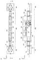
図1は、本実施例に係る基板処理装置の概略構成図である。本実施例に係る基板処理装置は、プラズマ気相成長(PE−CVD:Plasma Enhanced Chemical Vapor Deposition)によって基板上に薄膜を形成するPE−CVD装置であり、大別して、ロード部100、処理ユニット200、及びアンロード部300で構成されている。
FIG. 1 is a schematic configuration diagram of a substrate processing apparatus according to the present embodiment. The substrate processing apparatus according to the present embodiment is a PE-CVD apparatus that forms a thin film on a substrate by plasma enhanced chemical vapor deposition (PE-CVD), and is roughly divided into a
処理ユニット200は、処理前の基板Wを予熱するための予熱室230、基板W上にそれぞれ異なる薄膜を形成するための複数の成膜室240、処理後の基板Wを冷却するための冷却室250、基板Wを処理ユニット200内へ出し入れするためのロードロック室210,260、及びこれら各室へガラス基板Wを搬送するための搬送台車270を備えた共通搬送室220で構成されている。なお、本実施例においては予熱室230、成膜室240、及び冷却室250が、本発明に係る「基板処理室」に相当する。
The
予熱室230、成膜室240、及び冷却室250(以下、適宜「基板処理室」と総称する)は、いずれも共通搬送室220の上方に配置されている。これらの基板処理室230,240,250と共通搬送室220との間の境界部、すなわち各基板処理室230,240,250の床面には、基板Wを通過させることのできる開口(本発明の「基板通過口」に相当する)が設けられており、該開口を介して共通搬送室220と各基板処理室230,240,250の間で基板Wの搬入及び搬出が行われる。
The
更に、共通搬送室220とロードロック室210,260との境界部、及びロードロック室210,260と処理ユニット200の外部との境界部にも同様の開口が設けられている。これらの開口のうち、予熱室230及び冷却室250と共通搬送室220との境界部以外には、それぞれ開閉可能なゲートバルブ211,212,241,261,262が設けられており、各成膜室240及び共通搬送室220は図示しない真空ポンプによって真空状態に保たれている。また、ロードロック室210,260は、ロード部100から搬入された基板W、又はアンロード部300へ搬出する基板Wを一時的に保持するための予備真空室であり、真空ポンプによって適宜真空状態とすることができる。
Further, similar openings are provided at the boundary between the
また、ロード部100には、前段の工程から搬送されてきた基板Wをロードロック室210へと搬送するためのローラコンベアが設けられており、水平姿勢でロード部100に搬送されてきた被処理基板Wは、基板振り分け機構(図示略)によって左右方向(図1中のX軸方向)へ交互に振り分けられ、前記ローラコンベアによってロードロック室210の手前側左右の基板立ち上げ位置までそれぞれ搬送される。また、アンロード部300にも同様のローラコンベアが設けられており、ロードロック室260から搬出された基板Wは、該ローラコンベアによって後段の工程へ搬出される。
Further, the
以下、上記ローラコンベアについて詳述する。ロード部100に設けられたローラコンベアは、前段の工程から受け取ったガラス基板を水平姿勢で搬送するものであり、基板立ち上げ位置のローラコンベア110は、他の部分のローラコンベアとは別体に構成されている。該ローラコンベア110の構成を図2に示す。ローラコンベア110は枠体111と、枠体111により両端が軸支された複数のシャフト112を備えている。各シャフト112には複数のスリーブ113が取り付けられ、所定の駆動手段(図示略)によって各シャフト112を回転駆動することにより、スリーブ113上に載置された基板Wを一定方向に搬送することができる。また、枠体111は、回転軸114を中心に回動可能な構成となっており、所定の駆動機構(図示略)によって地面と垂直な状態に起立させることができる。
Hereinafter, the roller conveyor will be described in detail. The roller conveyor provided in the
更に、枠体111には、基板Wの左右二辺(すなわち起立時の上下二辺)に対応する位置に、起立状態の基板を搬送するための糸巻き状の起立搬送ローラ120が取り付けられている。起立搬送ローラ120は、回転軸と一体に形成された円柱形の筒状部と、筒状部の両端に設けられ基板Wの脱落を防止するためのフランジ部から成る。各ローラの回転軸は、それぞれ枠体111に設けられたローラ駆動部124に接続されており、枠体111Wを起立させた状態でこれらのローラ駆動部124によって各起立搬送ローラ120を一定方向に回転させることにより、上下の起立搬送ローラ120によって保持された基板Wを該ローラ120の配列方向に沿って移動させることができる。
Further, the
次に、上記ローラコンベア110からロードロック室210への基板Wの搬入手順について説明する。まず、ロード部100のローラコンベアによって、処理対象となる2枚のガラス基板Wをそれぞれ基板立ち上げ位置まで搬送する。図3は、このときの基板立ち上げ位置のローラコンベア110を示す側面図である。
Next, a procedure for carrying the substrate W from the
続いて、図4に示すように各ローラコンベア110を回転軸114を中心に回動させ、各コンベアに搭載された基板Wを互いに平行且つ地面に垂直な姿勢で対向させる。なお、このとき、基板Wはその上下2辺がローラコンベア110上の各起立搬送ローラ120のフランジによって保持されているため、ローラコンベア110を垂直状態まで起立させても該基板Wがローラコンベア110から脱落することはない。
Subsequently, as shown in FIG. 4, the
その後、ロードロック室210の真空側ゲートバルブ212を閉鎖した状態で大気側ゲートバルブ211を開放し、ローラコンベア110の各起立搬送ローラ120を所定の方向に回転させる。これによって、ローラコンベア110上の各基板Wがロードロック室210に向かって送り出され、開状態の大気側ゲートバルブ211を介してロードロック室210の内部へと搬入される。基板Wの搬入が完了するとロードロック室210の大気側ゲートバルブ211を閉鎖し、真空ポンプによってロードロック室210内を真空状態とする。
Thereafter, the atmosphere-
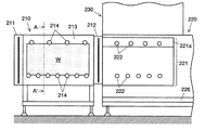
図5は基板Wの搬入完了時点におけるロードロック室210を示す正面断面図であり、図6は図5のA−A’矢視断面図である。ロードロック室210の内部には、上記同様の起立搬送ローラ214を複数備えた2枚の基板保持プレート213が対向配置されており、ロードロック室210に搬入された基板Wは、該起立搬送ローラ214によって上下2辺を支持されて基板保持プレート213上に保持される。各起立搬送ローラ214の回転軸は、各基板保持プレート213に設けられたローラ駆動部215に接続されており、これらのローラ駆動部215によって各ローラ214を所定方向に回動させることにより、各基板保持プレート213上の基板Wを共通搬送室220の方向(図5の右方向)に向かって搬送することができる。
FIG. 5 is a front sectional view showing the
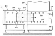
ロードロック室210内が所定の真空度に達したら、ロードロック室210の真空側ゲートバルブ212を開放し、基板保持プレート213上の起立搬送ローラ214を回転させて基板Wを共通搬送室220へ送出する(図7)。
When the inside of the
共通搬送室220には、ロードロック室210と同様に2枚の基板保持プレート221が設けられており、共通搬送室220内に進入した基板Wはその上下の端面が該基板保持プレート221上の起立搬送ローラ222によって保持され、該ローラ222の回転によって更に共通搬送室220の奥へと導かれる。
Similar to the
なお、図12〜14に示すように、各基板保持プレート221は共通搬送室220の外部に設けられたシリンダ225によって、互いに接近又は離間する方向(すなわち図1のX軸方向)に移動可能な構成となっている。また、共通搬送室220の各基板保持プレート221は、上下2枚のプレートを回転軸223を介して回動可能に連結した構成を有し、回転軸223を中心に上側のプレート221aを共通搬送室220の外側へ回動させることによって、該上側プレート221aに取り付けられたローラ222(すなわち基板上辺側の起立搬送ローラ)を、基板Wの上端縁を保持する保持位置と、基板Wの上方(すなわち基板昇降時の該基板Wの進路上)から退避した退避位置との間で移動させることができる(詳細は後述する)。
As shown in FIGS. 12 to 14, each
次に、該基板保持プレート221に保持された基板Wが、共通搬送室220内に設けられた搬送台車270へと受け渡される。図8に搬送台車270の構成を示す。搬送台車270は、垂直姿勢の基板をその厚さ方向と直交する方向に搬送するものであり、共通搬送室220内に敷設されたレール226上を走行するためのタイヤ273を備えた走行基台272と、走行基台272の上部に搭載された基板保持体271、及び走行基台272と基板保持体271との間に伸縮自在に連結されたパンタグラフ機構274を備えており、電動シリンダ275によってパンタグラフ機構274を伸縮させることにより基板保持体271を走行基台272上で上下移動させることができる構成となっている。なお、走行基台272の前後には基板の前後方向(図1のY軸方向)の移動を規制するための回転ストッパ276が設けられている。各ストッパ276は図示しない駆動機構によって回動可能な構成となっており、図8(b)に示すように、適宜、基板と干渉しない位置に退避させることができる。
Next, the substrate W held on the
基板保持体271は、走行基台272上方の前後両側に立設された一対のアームから成る。各アームの表裏両面には、基板Wの上辺及び下辺に対応する位置に、図9、図10に示すような基板保持ローラ280がそれぞれ取り付けられており、該ローラによって基板Wの上下2辺を保持することにより前記一対のアームの表側及び裏側に各1枚の基板Wを垂直姿勢で保持することができる。
The
基板保持ローラ280は、回転軸281と一体に形成された円柱形の筒状部282と、筒状部282の両端面の外周の一部に設けられた保持フランジ283a,bを備えている。各ローラの回転軸281は、それぞれ基板保持体271に設けられたローラ駆動部(図示略)に接続されており、これらのローラ駆動部によって各基板保持ローラ280を回転駆動することにより、その回転角度に応じて、基板Wを保持したり(図9)、解放したり(図10)することができる。以下、図9の状態を「基板保持状態」、図10の状態を「保持解除状態」と呼ぶ。基板保持状態では、図9(b)に示すように基板Wの端縁が両保持フランジ283a,bの間に位置した状態となるため、基板Wの厚さ方向の動きが規制される。一方、保持解除状態では、図10(b)に示すように基板Wと保持フランジ283a,bが干渉しない位置関係となるため、基板Wの厚さ方向の動きが規制されることはない。
The
共通搬送室220内の基板保持プレート221から搬送台車270へ基板Wを移載する際には、まず、図11、12に示すように搬送台車270を2枚の基板保持プレート221の間の空間に移動させる。続いて、シリンダ225によって各基板保持プレート221を基板搬送室の中央方向へ移動させることにより基板保持プレート221上の各基板Wを搬送台車270の基板保持体271に接近させる(図13)。なお、このとき、基板保持体271上の基板保持ローラ280は保持解除状態となっており、更に、基板保持プレート221上の起立搬送ローラ222と基板保持体271上の基板保持ローラ280は、図11に示すように互いに干渉しない位置に設けられているため、基板保持プレート221上の起立搬送ローラ222と基板保持体271上の基板保持ローラ280、及び基板保持体271上の基板保持ローラ280と基板Wとを接触させることなく各基板Wを基板保持体271に接近させることができる。
When the substrate W is transferred from the
その後、搬送台車270の基板保持体271上の基板保持ローラ280を回動させて基板保持状態とする。これにより、各基板Wが基板保持プレート221上の起立搬送ローラ222と基板保持体271上の基板保持ローラ280の双方によって保持された状態となる。
Thereafter, the
続いて、各基板保持プレート221の上側プレート221aが回転軸223を中心に外側へ回動し、基板Wの上辺を保持していた起立搬送ローラ222が退避位置へ移動する(図14)。その後、パンタグラフ機構274が伸長して基板保持体271が上昇し、該基板保持体271に搭載された2枚の基板Wが共通搬送室220の上方に設けられた予熱室230に搬入される(図15)。
Subsequently, the
以上により、予熱室230に搬入された基板Wは、搬送台車270の基板保持体271から予熱室230内に設けられた所定の基板保持機構へと受け渡される。
Thus, the substrate W carried into the preheating
ここで、該基板保持機構としては、例えば、図16に示すようなものを採用することができる。これは、共通搬送室220の基板保持プレート221とほぼ同様のものを上下に反転させた構成を有しており、2枚の基板保持プレート231をシリンダ234によって互いに接近又は離間させることができると共に、各基板保持プレート231の下側プレート231aを回動軸233を中心として予熱室230の外側へ回動させることで基板下辺を支持するためのローラ232を基板Wの進路上から退避させることができる。但し、予熱室230内では基板Wの水平方向への搬送は行わないため、各基板保持プレート231上のローラ232は回動可能とする必要はない。
Here, for example, the substrate holding mechanism shown in FIG. 16 can be adopted. This has a configuration in which the substantially same
上記のような基板保持機構を備えた予熱室230に基板を搬入する際には、まず、下側プレート231aに取り付けられたローラ232を退避位置に移動させた上で搬送台車270の基板保持体271を両基板保持プレート231の間に進入させる(図16(a))。続いて、前記下側プレート231a上のローラ232を保持位置に戻して基板Wを保持すると共に基板保持体271の基板保持ローラ280を保持解除状態とする(図16(b))。その後、シリンダ234によって各基板保持プレート231を予熱室230の外側方向に移動させた上で、搬送台車270のパンタグラフ機構274を縮めて基板保持体271を共通搬送室220へと下降させる。
When the substrate is carried into the preheating
なお、予熱室230内に設けられる基板保持機構は上記構成のものに限られず、例えば、一方の面に図9、10と同様の複数の基板保持ローラを備え、該基板保持ローラによって基板Wの上下2辺を保持可能な2枚の板状部材を予熱室230の内部に設け、該2枚の板状部材をローラ取付面を内側にして対向配置すると共に、各板状部材を互いに接近又は離間する方向へ移動可能な構成としたものであってもよい。このような基板保持機構を備えた予熱室230に基板Wを搬入する際には、まず、該2枚の板状部材を離間させた状態で両者の間に搬送台車270の基板保持体271を進入させ、その後、各板状部材を移動させて基板保持体271に接近させる。続いて、各板状部材の基板保持ローラを基板保持状態に、基板保持体271の基板保持ローラ280を保持解除状態とすることにより、各基板Wを基板保持体271の基板保持ローラ280から前期板状部材上の基板保持ローラへと掴み換え、基板Wを搭載した各板状部材を再び互いに離間する方向へ移動させた上で、基板保持体271を予熱室230から退避させる。
The substrate holding mechanism provided in the preheating
予熱室230での処理が完了すると、上記搬入時とは逆の手順により各ガラス基板Wが予熱室230内の各基板保持プレート231から搬送台車270の基板保持体271へと受け渡され、共通搬送室220へ搬出される。その後、共通搬送室220に敷設されたレール226に沿って走行基台272を走行させることで後段の成膜室240の直下に搬送台車270を移動させ、上記と同様の手順により基板Wの搬入出を行う。
When the processing in the preheating
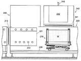
このときの成膜室240の断面を図18に示す。成膜室240の中央には給電部243を備えた電極242が設けられ、該電極242を挟んで対向する位置に上記予熱室230と同様の基板保持プレート231が設けられている(図16と対応する構成については同一符号を付し、説明を省略する)。なお、電極242の前後方向(図1のY軸方向)の長さは、搬送台車270上の基板保持体271の一対のアームの間隔よりも小さくなっており、成膜室240へ基板保持体271を進入させた際には電極242が両アームの間に位置した状態となるため、基板保持体271と電極242とが干渉することはない。また、成膜室240と共通搬送室220との間の開口は通常はゲートバルブ241によって閉鎖されており、基板Wを搬入及び搬出するときのみ該ゲートバルブを241開放して基板Wを通過させる。
A cross section of the
以上のように、本実施例に係る基板処理装置によれば、各基板処理室を共通搬送室の上に重ねて配置すると共に、共通搬送室−基板処理室間での基板の出し入れを両者の境界部、すなわち、各基板処理室の床面に設けられた開口(基板通過口)から行う構成としたことにより、各基板処理室間の間隔を短くすることができ、一層の省スペース化を図ることができる。また、上記のように共通搬送室内を走行可能且つ基板を上下に昇降可能な搬送台車を設けることにより、共通搬送室内における基板の水平搬送と各基板処理室への基板の上下搬送とを一台の搬送台車で行うことが可能となる。このため、水平搬送装置と上下搬送装置を別途設ける場合に比べ、製造コスト及び搬送装置の保守管理に要するコストを抑えることができる。また更に、共通搬送室内において垂直姿勢の基板をその厚さ方向と直交する方向に搬送する構成としたことにより、該共通搬送室の体積を低減し、更なる省スペース化、低コスト化、及び軽量化を図ることができる。 As described above, according to the substrate processing apparatus according to the present embodiment, the substrate processing chambers are arranged so as to overlap the common transfer chamber, and the substrate is loaded and unloaded between the common transfer chamber and the substrate processing chamber. By adopting a configuration in which the boundary portion, that is, the opening (substrate passage opening) provided on the floor surface of each substrate processing chamber is used, the interval between the substrate processing chambers can be shortened, and further space saving is achieved. Can be planned. In addition, by providing the transport carriage that can run in the common transport chamber and can move the substrate up and down as described above, one unit for horizontal transport of substrates in the common transport chamber and vertical transport of substrates to each substrate processing chamber. It becomes possible to carry out with the conveyance cart of this. For this reason, compared with the case where a horizontal conveying apparatus and an up-and-down conveying apparatus are provided separately, the manufacturing cost and the cost required for maintenance management of a conveying apparatus can be held down. Furthermore, by adopting a configuration in which the substrate in the vertical posture is transported in the direction perpendicular to the thickness direction in the common transport chamber, the volume of the common transport chamber is reduced, further space saving, cost reduction, and Weight reduction can be achieved.
110…ローラコンベア
120,214,222…起立搬送ローラ
210,260…ロードロック室
211,212,241,261,262…ゲートバルブ
213,221,231…基板保持プレート
214,222…起立搬送ローラ
220…共通搬送室
221a…上側プレート
226…レール
230…予熱室
231a…下側プレート
240…成膜室
250…冷却室
270…搬送台車
271…基板保持体
272…走行基台
274…パンタグラフ機構
280…基板保持ローラ
W…基板
110:
Claims (4)
a) 複数の基板処理室と、
b) 各基板処理室へ基板を搬送するための共通搬送室と、
を有し、少なくとも一つの基板処理室が前記共通搬送室の上方又は下方に設けられ、該基板処理室と共通搬送室の境界部に基板が通り抜け可能な基板通過口が設けられていることを特徴とする基板処理装置。 In a substrate processing apparatus that performs a predetermined process on a substrate while conveying the substrate in an upright posture,
a) multiple substrate processing chambers;
b) a common transfer chamber for transferring substrates to each substrate processing chamber;
And at least one substrate processing chamber is provided above or below the common transfer chamber, and a substrate passage port through which the substrate can pass is provided at the boundary between the substrate processing chamber and the common transfer chamber. A substrate processing apparatus.
Priority Applications (5)
| Application Number | Priority Date | Filing Date | Title |
|---|---|---|---|
| JP2007272694A JP2009105081A (en) | 2007-10-19 | 2007-10-19 | Substrate processing apparatus |
| PCT/JP2008/002708 WO2009050849A1 (en) | 2007-10-19 | 2008-09-29 | Substrate processing apparatus |
| CN200880112243A CN101827766A (en) | 2007-10-19 | 2008-09-29 | Substrate processing apparatus |
| EP08839220A EP2213595A1 (en) | 2007-10-19 | 2008-09-29 | Substrate processing apparatus |
| US12/682,641 US20100243163A1 (en) | 2007-10-19 | 2008-09-29 | Substrate processing apparatus |
Applications Claiming Priority (1)
| Application Number | Priority Date | Filing Date | Title |
|---|---|---|---|
| JP2007272694A JP2009105081A (en) | 2007-10-19 | 2007-10-19 | Substrate processing apparatus |
Publications (2)
| Publication Number | Publication Date |
|---|---|
| JP2009105081A true JP2009105081A (en) | 2009-05-14 |
| JP2009105081A5 JP2009105081A5 (en) | 2010-09-02 |
Family
ID=40567138
Family Applications (1)
| Application Number | Title | Priority Date | Filing Date |
|---|---|---|---|
| JP2007272694A Pending JP2009105081A (en) | 2007-10-19 | 2007-10-19 | Substrate processing apparatus |
Country Status (5)
| Country | Link |
|---|---|
| US (1) | US20100243163A1 (en) |
| EP (1) | EP2213595A1 (en) |
| JP (1) | JP2009105081A (en) |
| CN (1) | CN101827766A (en) |
| WO (1) | WO2009050849A1 (en) |
Cited By (11)
| Publication number | Priority date | Publication date | Assignee | Title |
|---|---|---|---|---|
| KR101036123B1 (en) * | 2010-06-10 | 2011-05-23 | 에스엔유 프리시젼 주식회사 | Apparatus for depositing film |
| WO2011142351A1 (en) * | 2010-05-12 | 2011-11-17 | シャープ株式会社 | Substrate-mounting carriage |
| JP2012158802A (en) * | 2011-01-31 | 2012-08-23 | Ihi Corp | Antenna carrier, array antenna type plasma cvd device, and method for carrying antenna for array antenna type plasma cvd device and substrate |
| JP2013157475A (en) * | 2012-01-30 | 2013-08-15 | Ulvac Japan Ltd | Film forming device |
| KR101394367B1 (en) | 2012-09-27 | 2014-05-27 | 주식회사 선익시스템 | Apparatus for processing substrate and method for processing substrate |
| KR101405102B1 (en) | 2012-10-04 | 2014-06-10 | 주식회사 선익시스템 | Apparatus for processing substrate and method for processing substrate |
| JP2015025173A (en) * | 2013-07-26 | 2015-02-05 | トヨタ自動車株式会社 | Plasma film deposition device and plasma film deposition method |
| KR101488944B1 (en) | 2012-09-24 | 2015-02-06 | 주식회사 선익시스템 | Apparatus for supplying evaporation material and Apparatus for deposition having the same |
| WO2015072691A1 (en) * | 2013-11-15 | 2015-05-21 | 코닉이앤씨 주식회사 | Atomic layer deposition apparatus and method |
| JP2015534264A (en) * | 2012-09-10 | 2015-11-26 | アプライド マテリアルズ インコーポレイテッドApplied Materials,Incorporated | Substrate processing system and method for processing a substrate |
| CN107615446A (en) * | 2015-05-21 | 2018-01-19 | 东京毅力科创株式会社 | Processing system |
Families Citing this family (11)
| Publication number | Priority date | Publication date | Assignee | Title |
|---|---|---|---|---|
| US9922854B2 (en) * | 2010-04-30 | 2018-03-20 | Applied Materials, Inc. | Vertical inline CVD system |
| KR101708420B1 (en) * | 2010-09-15 | 2017-02-21 | 삼성디스플레이 주식회사 | Depositing system for substrate and depositing method using the same |
| WO2012050081A1 (en) * | 2010-10-12 | 2012-04-19 | 株式会社カネカ | Manufacturing device for organic el elements |
| DE102011085789B4 (en) * | 2011-11-04 | 2015-02-12 | Von Ardenne Gmbh | Vertical continuous coating machine for continuous vacuum coating of substrates |
| CN105177514B (en) * | 2014-05-28 | 2018-04-10 | 佳能安内华股份有限公司 | Substrate board treatment |
| KR102605917B1 (en) * | 2016-04-07 | 2023-11-27 | 주식회사 탑 엔지니어링 | Scribing apparatus |
| JP6846943B2 (en) * | 2017-02-10 | 2021-03-24 | 東京エレクトロン株式会社 | Coating device and coating method |
| DE102019102492A1 (en) * | 2019-01-31 | 2020-08-06 | Fraunhofer-Gesellschaft zur Förderung der angewandten Forschung e.V. | Device and method for processing wafers |
| CN110504331B (en) * | 2019-07-29 | 2021-03-23 | 中建材智能自动化研究院有限公司 | Full-automatic photovoltaic backplate glass production line |
| TWI737520B (en) * | 2020-08-14 | 2021-08-21 | 友達光電股份有限公司 | Display panel |
| IT202000024337A1 (en) * | 2020-10-15 | 2022-04-15 | Bottero Spa | METHOD AND SHUTTLE FOR MOVING A GLASS PLATE |
Citations (2)
| Publication number | Priority date | Publication date | Assignee | Title |
|---|---|---|---|---|
| JPH08196894A (en) * | 1995-01-25 | 1996-08-06 | Tokki Kk | Constitution for reducing size and cost of vacuum device and form of transporting material |
| JP2002246435A (en) * | 2001-02-16 | 2002-08-30 | Ishikawajima Harima Heavy Ind Co Ltd | Substrate processor and substrate-processing method |
Family Cites Families (2)
| Publication number | Priority date | Publication date | Assignee | Title |
|---|---|---|---|---|
| JP3582330B2 (en) * | 1997-11-14 | 2004-10-27 | 東京エレクトロン株式会社 | Processing apparatus and processing system using the same |
| JP2003192127A (en) | 2002-12-03 | 2003-07-09 | Takehide Hayashi | Flat panel sheet conveying system |
-
2007
- 2007-10-19 JP JP2007272694A patent/JP2009105081A/en active Pending
-
2008
- 2008-09-29 US US12/682,641 patent/US20100243163A1/en not_active Abandoned
- 2008-09-29 WO PCT/JP2008/002708 patent/WO2009050849A1/en active Application Filing
- 2008-09-29 EP EP08839220A patent/EP2213595A1/en not_active Withdrawn
- 2008-09-29 CN CN200880112243A patent/CN101827766A/en active Pending
Patent Citations (2)
| Publication number | Priority date | Publication date | Assignee | Title |
|---|---|---|---|---|
| JPH08196894A (en) * | 1995-01-25 | 1996-08-06 | Tokki Kk | Constitution for reducing size and cost of vacuum device and form of transporting material |
| JP2002246435A (en) * | 2001-02-16 | 2002-08-30 | Ishikawajima Harima Heavy Ind Co Ltd | Substrate processor and substrate-processing method |
Cited By (13)
| Publication number | Priority date | Publication date | Assignee | Title |
|---|---|---|---|---|
| WO2011142351A1 (en) * | 2010-05-12 | 2011-11-17 | シャープ株式会社 | Substrate-mounting carriage |
| KR101036123B1 (en) * | 2010-06-10 | 2011-05-23 | 에스엔유 프리시젼 주식회사 | Apparatus for depositing film |
| WO2011155652A1 (en) * | 2010-06-10 | 2011-12-15 | 에스엔유 프리시젼 주식회사 | Thin film deposition device and thin film deposition system |
| CN103097568A (en) * | 2010-06-10 | 2013-05-08 | Snu精密股份有限公司 | Thin film deposition device and thin film deposition system |
| JP2012158802A (en) * | 2011-01-31 | 2012-08-23 | Ihi Corp | Antenna carrier, array antenna type plasma cvd device, and method for carrying antenna for array antenna type plasma cvd device and substrate |
| JP2013157475A (en) * | 2012-01-30 | 2013-08-15 | Ulvac Japan Ltd | Film forming device |
| JP2015534264A (en) * | 2012-09-10 | 2015-11-26 | アプライド マテリアルズ インコーポレイテッドApplied Materials,Incorporated | Substrate processing system and method for processing a substrate |
| KR101488944B1 (en) | 2012-09-24 | 2015-02-06 | 주식회사 선익시스템 | Apparatus for supplying evaporation material and Apparatus for deposition having the same |
| KR101394367B1 (en) | 2012-09-27 | 2014-05-27 | 주식회사 선익시스템 | Apparatus for processing substrate and method for processing substrate |
| KR101405102B1 (en) | 2012-10-04 | 2014-06-10 | 주식회사 선익시스템 | Apparatus for processing substrate and method for processing substrate |
| JP2015025173A (en) * | 2013-07-26 | 2015-02-05 | トヨタ自動車株式会社 | Plasma film deposition device and plasma film deposition method |
| WO2015072691A1 (en) * | 2013-11-15 | 2015-05-21 | 코닉이앤씨 주식회사 | Atomic layer deposition apparatus and method |
| CN107615446A (en) * | 2015-05-21 | 2018-01-19 | 东京毅力科创株式会社 | Processing system |
Also Published As
| Publication number | Publication date |
|---|---|
| CN101827766A (en) | 2010-09-08 |
| US20100243163A1 (en) | 2010-09-30 |
| EP2213595A1 (en) | 2010-08-04 |
| WO2009050849A1 (en) | 2009-04-23 |
Similar Documents
| Publication | Publication Date | Title |
|---|---|---|
| JP2009105081A (en) | Substrate processing apparatus | |
| JP2009094242A (en) | Substrate holding mechanism, substrate delivery mechanism, and substrate treating equipment | |
| JP5819458B2 (en) | Substrate processing equipment | |
| JP4954162B2 (en) | Processing system | |
| JP5173699B2 (en) | Organic EL device manufacturing equipment | |
| TWI232242B (en) | Substrate processing apparatus and processing method | |
| JP2009105081A5 (en) | ||
| JP2009146932A (en) | Substrate transfer apparatus, substrate transfer method, and vacuum processing apparatus | |
| TW201733887A (en) | Vacuum processing apparatus | |
| JP5730322B2 (en) | Vapor deposition apparatus and vapor deposition method | |
| KR102173658B1 (en) | Substrate processing system | |
| JP2005340425A (en) | Vacuum treatment device | |
| WO2012140799A1 (en) | Deposition apparatus | |
| JP2003258058A (en) | Substrate treatment device operating method | |
| JP5260212B2 (en) | Deposition equipment | |
| KR101688842B1 (en) | Substrate processing apparatus | |
| JP2004083997A (en) | Vertical type chemical vapor deposition system and deposition method using this system | |
| KR101039231B1 (en) | Apparutus for manufacturing substrate | |
| JP2012169534A (en) | Substrate processing device and method of manufacturing semiconductor device | |
| JP2014036159A (en) | Transfer mechanism of workpiece and vacuum processing apparatus | |
| JPH05326666A (en) | Conveyor | |
| KR101069537B1 (en) | Apparutus for manufacturing substrate | |
| KR101576547B1 (en) | Cassette supplying system | |
| KR101553611B1 (en) | A buffer for inline printing system | |
| KR100934765B1 (en) | Apparatus for manufacturing flat panel display |
Legal Events
| Date | Code | Title | Description |
|---|---|---|---|
| A521 | Written amendment |
Free format text: JAPANESE INTERMEDIATE CODE: A523 Effective date: 20100708 |
|
| A621 | Written request for application examination |
Free format text: JAPANESE INTERMEDIATE CODE: A621 Effective date: 20100708 |
|
| RD02 | Notification of acceptance of power of attorney |
Free format text: JAPANESE INTERMEDIATE CODE: A7422 Effective date: 20100708 |
|
| A521 | Written amendment |
Free format text: JAPANESE INTERMEDIATE CODE: A523 Effective date: 20100727 |
|
| A131 | Notification of reasons for refusal |
Free format text: JAPANESE INTERMEDIATE CODE: A131 Effective date: 20111206 |
|
| A02 | Decision of refusal |
Free format text: JAPANESE INTERMEDIATE CODE: A02 Effective date: 20120403 |