US9315015B2 - Printed material fixing piece, printing device, and printing method - Google Patents
Printed material fixing piece, printing device, and printing method Download PDFInfo
- Publication number
- US9315015B2 US9315015B2 US14/365,029 US201314365029A US9315015B2 US 9315015 B2 US9315015 B2 US 9315015B2 US 201314365029 A US201314365029 A US 201314365029A US 9315015 B2 US9315015 B2 US 9315015B2
- Authority
- US
- United States
- Prior art keywords
- printed matter
- fixing
- printed
- stage
- printed substrate
- Prior art date
- Legal status (The legal status is an assumption and is not a legal conclusion. Google has not performed a legal analysis and makes no representation as to the accuracy of the status listed.)
- Active
Links
Images


Classifications
-
- H—ELECTRICITY
- H01—ELECTRIC ELEMENTS
- H01L—SEMICONDUCTOR DEVICES NOT COVERED BY CLASS H10
- H01L21/00—Processes or apparatus adapted for the manufacture or treatment of semiconductor or solid state devices or of parts thereof
- H01L21/02—Manufacture or treatment of semiconductor devices or of parts thereof
- H01L21/027—Making masks on semiconductor bodies for further photolithographic processing not provided for in group H01L21/18 or H01L21/34
- H01L21/0271—Making masks on semiconductor bodies for further photolithographic processing not provided for in group H01L21/18 or H01L21/34 comprising organic layers
- H01L21/0273—Making masks on semiconductor bodies for further photolithographic processing not provided for in group H01L21/18 or H01L21/34 comprising organic layers characterised by the treatment of photoresist layers
-
- B—PERFORMING OPERATIONS; TRANSPORTING
- B41—PRINTING; LINING MACHINES; TYPEWRITERS; STAMPS
- B41F—PRINTING MACHINES OR PRESSES
- B41F3/00—Cylinder presses, i.e. presses essentially comprising at least one cylinder co-operating with at least one flat type-bed
- B41F3/18—Cylinder presses, i.e. presses essentially comprising at least one cylinder co-operating with at least one flat type-bed of special construction or for particular purposes
- B41F3/20—Cylinder presses, i.e. presses essentially comprising at least one cylinder co-operating with at least one flat type-bed of special construction or for particular purposes with fixed type-beds and travelling impression cylinders
-
- B—PERFORMING OPERATIONS; TRANSPORTING
- B41—PRINTING; LINING MACHINES; TYPEWRITERS; STAMPS
- B41F—PRINTING MACHINES OR PRESSES
- B41F21/00—Devices for conveying sheets through printing apparatus or machines
- B41F21/04—Grippers
- B41F21/06—Suction-operated grippers
-
- B—PERFORMING OPERATIONS; TRANSPORTING
- B41—PRINTING; LINING MACHINES; TYPEWRITERS; STAMPS
- B41F—PRINTING MACHINES OR PRESSES
- B41F17/00—Printing apparatus or machines of special types or for particular purposes, not otherwise provided for
- B41F17/08—Printing apparatus or machines of special types or for particular purposes, not otherwise provided for for printing on filamentary or elongated articles, or on articles with cylindrical surfaces
- B41F17/14—Printing apparatus or machines of special types or for particular purposes, not otherwise provided for for printing on filamentary or elongated articles, or on articles with cylindrical surfaces on articles of finite length
-
- B—PERFORMING OPERATIONS; TRANSPORTING
- B41—PRINTING; LINING MACHINES; TYPEWRITERS; STAMPS
- B41F—PRINTING MACHINES OR PRESSES
- B41F3/00—Cylinder presses, i.e. presses essentially comprising at least one cylinder co-operating with at least one flat type-bed
- B41F3/18—Cylinder presses, i.e. presses essentially comprising at least one cylinder co-operating with at least one flat type-bed of special construction or for particular purposes
- B41F3/30—Cylinder presses, i.e. presses essentially comprising at least one cylinder co-operating with at least one flat type-bed of special construction or for particular purposes for lithography
- B41F3/34—Cylinder presses, i.e. presses essentially comprising at least one cylinder co-operating with at least one flat type-bed of special construction or for particular purposes for lithography for offset printing
-
- B—PERFORMING OPERATIONS; TRANSPORTING
- B41—PRINTING; LINING MACHINES; TYPEWRITERS; STAMPS
- B41F—PRINTING MACHINES OR PRESSES
- B41F3/00—Cylinder presses, i.e. presses essentially comprising at least one cylinder co-operating with at least one flat type-bed
- B41F3/46—Details
- B41F3/51—Type-beds; Supports therefor
-
- B—PERFORMING OPERATIONS; TRANSPORTING
- B41—PRINTING; LINING MACHINES; TYPEWRITERS; STAMPS
- B41J—TYPEWRITERS; SELECTIVE PRINTING MECHANISMS, i.e. MECHANISMS PRINTING OTHERWISE THAN FROM A FORME; CORRECTION OF TYPOGRAPHICAL ERRORS
- B41J11/00—Devices or arrangements of selective printing mechanisms, e.g. ink-jet printers or thermal printers, for supporting or handling copy material in sheet or web form
- B41J11/0085—Using suction for maintaining printing material flat
-
- B—PERFORMING OPERATIONS; TRANSPORTING
- B41—PRINTING; LINING MACHINES; TYPEWRITERS; STAMPS
- B41J—TYPEWRITERS; SELECTIVE PRINTING MECHANISMS, i.e. MECHANISMS PRINTING OTHERWISE THAN FROM A FORME; CORRECTION OF TYPOGRAPHICAL ERRORS
- B41J3/00—Typewriters or selective printing or marking mechanisms characterised by the purpose for which they are constructed
- B41J3/407—Typewriters or selective printing or marking mechanisms characterised by the purpose for which they are constructed for marking on special material
-
- H—ELECTRICITY
- H01—ELECTRIC ELEMENTS
- H01L—SEMICONDUCTOR DEVICES NOT COVERED BY CLASS H10
- H01L21/00—Processes or apparatus adapted for the manufacture or treatment of semiconductor or solid state devices or of parts thereof
- H01L21/02—Manufacture or treatment of semiconductor devices or of parts thereof
- H01L21/027—Making masks on semiconductor bodies for further photolithographic processing not provided for in group H01L21/18 or H01L21/34
-
- B—PERFORMING OPERATIONS; TRANSPORTING
- B41—PRINTING; LINING MACHINES; TYPEWRITERS; STAMPS
- B41M—PRINTING, DUPLICATING, MARKING, OR COPYING PROCESSES; COLOUR PRINTING
- B41M1/00—Inking and printing with a printer's forme
- B41M1/06—Lithographic printing
-
- B—PERFORMING OPERATIONS; TRANSPORTING
- B41—PRINTING; LINING MACHINES; TYPEWRITERS; STAMPS
- B41P—INDEXING SCHEME RELATING TO PRINTING, LINING MACHINES, TYPEWRITERS, AND TO STAMPS
- B41P2200/00—Printing processes
- B41P2200/20—Lithography
-
- B—PERFORMING OPERATIONS; TRANSPORTING
- B41—PRINTING; LINING MACHINES; TYPEWRITERS; STAMPS
- B41P—INDEXING SCHEME RELATING TO PRINTING, LINING MACHINES, TYPEWRITERS, AND TO STAMPS
- B41P2219/00—Printing presses using a heated printing foil
- B41P2219/40—Material or products to be decorated or printed
- B41P2219/42—Sheet-like material
Definitions
- the present application relates to an apparatus for fixing a printed matter, a printing device including the same and a printing method including the same.
- a conductive pattern for an electrode a black matrix pattern and a color pattern for a color filter, an insulating pattern and a resist pattern for a thin film transistor (TFT), and the like are required.
- TFT thin film transistor
- the patterns may be formed by a photolithography method, and the like, but a pattern forming method using a printing method has been attempted in consideration of process costs or efficiency.
- the present application has been made in an effort to provide a printing method and a printing device, which may improve process efficiency by forming a precise electronic material pattern, or forming a pattern on a plurality of printed matters in one printing.
- An exemplary embodiment of the present application provides an apparatus for fixing a printed matter including a plurality of engraved portions which may fix a plurality of printed matters, and at least one vacuum hole or vacuum passage provided at a lower portion of the engraved portion.
- Another exemplary embodiment of the present application provides a printing device including the apparatus for fixing a printed matter.
- Still another exemplary embodiment of the present application provides a printing method using the apparatus for fixing a printed matter.
- the apparatus for fixing a printed matter may efficiently fix and align the printed matter when mounting the printed matter on a printed matter stage, and may fix one or more printed matters on one apparatus for fixing a printed matter, and thus is advantageous in that patterns may be formed on a plurality of printed matters in one printing. Therefore, there is an advantage in that the precision of the printing pattern is enhanced, the process efficiency is improved, and process costs are reduced.
- FIG. 1 illustrates a reverse offset printing process
- FIG. 2 illustrates a side view of an apparatus for fixing a printed matter according to an exemplary embodiment of the present application.
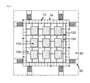
- FIG. 3 illustrates a plan view of the apparatus for fixing a printed matter according to an exemplary embodiment of the present application when observed from above.
- FIG. 4 illustrates that the apparatus for fixing a printed matter according to an exemplary embodiment of the present application is mounted on a printed matter stage with a plan view when observed from above.
- FIG. 5 illustrates that a printed matter is fixed to the apparatus for fixing a printed matter according to an exemplary embodiment of the present application and thus is mounted on a printed matter stage with a plan view when observed from above.
- FIGS. 6 and 7 illustrate a side view of a printed matter stage of a printing device according to an exemplary embodiment of the present application.
- FIGS. 8 and 9 illustrate a side view of a vacuum suction portion of the printed matter stage of the printing device according to an exemplary embodiment of the present application.
- FIGS. 10 and 11 illustrate a plan view of the printed matter stage of the printing device according to an exemplary embodiment of the present application.
- FIG. 12 illustrates an example of operating a position control portion of a stage for mounting a cliché according to an exemplary embodiment of a printing device according to the present application.
- An exemplary embodiment of the present application provides an apparatus for fixing a printed matter 100 used in a printing device.
- the apparatus for fixing a printed matter 100 may include a plurality of engraved portions 110 which may fix a plurality of printed matters; and at least one vacuum hole 122 and/or at least one vacuum passage 124 provided at a lower portion of the engraved portion 110 .
- the apparatus for fixing a printed matter 100 may fix a printed matter 40 at each engraved portion 110 .
- the apparatus for fixing a printed matter 100 may include two or more engraved portions 110 which may fix two or more printed matters; and at least one vacuum hole 122 and/or a least one vacuum passage 124 provided at a lower portion of the engraved portion 110 .
- one apparatus for fixing a printed matter may fix two or more printed matters simultaneously, and thus is advantageous in that printing patterns may be formed on two or more printed matters in one printing.
- the apparatus for fixing a printed matter 100 may include four or more engraved portions 110 which may fix four or more printed matters; and at least one vacuum hole 122 and/or at least one vacuum passage 124 provided at a lower portion of the engraved portion 110 .
- one apparatus for fixing a printed matter may fix four or more printed matters simultaneously, and thus is advantageous in that printing patterns may be formed on four or more printed matters in one printing.
- the apparatus for fixing a printed matter 100 may include six or more engraved portions 110 which may fix six or more printed matters; and at least one vacuum hole 122 and/or at least one vacuum passage 124 provided at a lower portion of the engraved portion 110 .
- one apparatus for fixing a printed matter may fix six or more printed matters simultaneously, and thus is advantageous in that printing patterns may be formed on six or more printed matters in one printing.
- the apparatus for fixing a printed matter 100 may include eight or more engraved portions 110 which may fix eight or more printed matters; and at least one vacuum hole 122 and/or at least one vacuum passage 124 provided at a lower portion of the engraved portion 110 .
- one apparatus for fixing a printed matter may fix eight or more printed matters simultaneously, and thus is advantageous in that printing patterns may be formed on eight or more printed matters in one printing.
- the apparatus for fixing a printed matter 100 may include nine or more engraved portions 110 which may fix nine or more printed matters; and at least one vacuum hole 122 and/or at least one vacuum passage 124 provided at a lower portion of the engraved portion 110 .
- one apparatus for fixing a printed matter may fix nine or more printed matters simultaneously, and thus is advantageous in that printing patterns may be formed on nine or more printed matters in one printing.
- One or two or more vacuum holes 122 and/or one or two or more vacuum passages 124 may be provided at a lower portion of each engraved portion 110 .
- FIG. 2 illustrates a side view of the apparatus for fixing a printed matter according to an exemplary embodiment of the present application
- FIG. 3 illustrates a plan view of the apparatus when observed from above.
- the printed matter 40 means a printing object on which a printing pattern is transferred or an object to be printed, and may be, for example, a substrate. Further, the substrate may be glass or plastic.
- a printing process by which the apparatus for fixing a printed matter according to an exemplary embodiment of the present application is used may be a reverse offset printing process.
- FIG. 1 illustrates an exemplary embodiment of the reverse offset printing process.
- a printing roll includes a printing roll stage 20 and a blanket 21 provided to cover the surface of the printing roll stage.
- a printing matter 22 is coated on a blanket 21 of the printing roll using a coating portion 10 .
- a printing matter pattern 41 is formed on the blanket 21 by removing a part of a printing matter pattern 32 from the blanket 21 of the printing roll by bringing the blanket 21 of the printing roll in contact with a cliché 31 provided on a cliché stage 30 .
- the printing matter pattern 41 is transferred on the printed matter 40 by bringing the blanket 21 of the printing roll in contact with the printed matter 40 .
- the apparatus for fixing a printed matter 100 may be mounted on a printed matter stage 42 .
- the printed matter stage 42 means a support portion of the printed matter, on which the printed matter may be placed.
- the apparatus for fixing a printed matter may be attached to and detached from a printed matter stage, and thus is advantageous in that it is facilitated to simultaneously form a plurality of printing patterns in one printing by fixing a plurality of printed matters.
- a printed matter 40 may be fixed to an upper portion of the apparatus for fixing a printed matter 100 , and a printed matter stage 42 may be provided at a lower portion of the apparatus for fixing a printed matter.
- the vacuum hole 122 and/or vacuum passage 124 may be disposed at a lower portion of the engraved portion 110 , and one or two or more vacuum holes 122 and/or vacuum passages 124 may be provided at a lower portion of one engraved portion 110 .
- the vacuum hole 122 and/or vacuum passage 124 may also be disposed at a portion in which the engraved portion 110 is not present in the apparatus for fixing a printed matter 100 .
- FIGS. 2 and 3 illustrate the side structure of the vacuum hole 122 and the vacuum passage 124 disposed at a lower portion of the engraved portion 110 and a plan view thereof when observed from above.
- the surface may include a structure of the vacuum passage 124 composed of a groove. Intersection points having a lattice form of the structure of the vacuum passage 124 composed of a groove may have a structure of a hole 122 .
- the shape and diameter of the hole, or the shape, width and depth of the groove of the structure of the passage are not particularly limited as long as the printed matter 40 may be fixed to the apparatus for fixing a printed matter 100 without being deformed by the vacuum hole 122 and the vacuum passage 124 .
- the diameter of the vacuum hole 122 may be one to 15 times the thickness of the printed matter, but is not limited thereto.
- the width of the vacuum passage 124 may be one to 10 times the thickness of the printed matter, but is not limited thereto.
- vacuum refers to the state where pressure is lower than normal pressure (760 mmHg), and the degree of vacuum means a pressure of the remaining gas in a container under vacuum when compared to the state of vacuum with respect to normal pressure.
- the degree of vacuum of the vacuum adsorption is not particularly limited as long as the printed matter may be fixed to the apparatus for fixing a printed matter without being deformed by the vacuum hole 122 and the vacuum passage 124 .
- the degree of vacuum of the vacuum adsorption may be 5% or less of normal pressure.
- the degree of vacuum of the vacuum hole 122 and vacuum passage 124 may be 50 mmHg or less.
- the lower limit of the degree of vacuum of the vacuum hole 122 and vacuum passage 124 is not particularly limited as long as the printed matter is not deformed by the vacuum hole 122 and vacuum passage 124 according to the type and thickness of the printed matter used.
- FIG. 4 illustrates that the apparatus for fixing a printed matter 100 according to an exemplary embodiment of the present application is mounted on a printed matter stage 42 with a plan view when observed from above
- FIG. 5 illustrates that a printed matter 40 is fixed to the apparatus for fixing a printed matter 100 according to an exemplary embodiment of the present application and thus is mounted on a printed matter stage 42 with a plan view when observed from above.
- the engraved portion 110 is disposed at an upper portion of the apparatus for fixing a printed matter 100 , and may be formed such that the printed matter may be arranged and installed.
- the engraved portion 110 may include a projection or groove for fixing a printed matter at the inner side thereof.
- the shape of the projection or groove is not particularly limited as long as the shape has a structure capable of facilitating the fixation of the printed matter 40 .
- the shape of the cross-section of the projection or groove may be a circular, triangular, quadrangular, or trapezoidal shape.
- the depth of the engraved portion 110 may be equal to or smaller than the thickness of the printed matter 40 .
- the depth of the engraved portion 110 is larger than the thickness of the printed matter 40 , it is difficult to vacuum-adsorb the apparatus for fixing a printed matter 100 to the printed matter stage 42 because there is no place where the vacuum hole 122 and the vacuum passage 124 are formed.
- the depth deviation of the engraved portion 110 may be 100 ⁇ m or less. Specifically, the deviation between depths of a plurality of engraved portions 110 may be 100 ⁇ m or less. When the depth deviation of the engraved portion 110 is 100 ⁇ m or less, the precision of the level difference between printed matters is improved when the printed matter 40 is fixed, and thus, the precision of the printing pattern 41 printed on the printed matter 40 is also good.
- the printed matter stage 42 may further include a position control portion 50 for aligning the printed matter.
- the position control portion of the printed matter stage may control a position on a plane.
- the position control portion of the printed matter stage may have a configuration in which a microscopic position of the printed matter stage is controlled to three positions, that is, a position in the x direction, a position in the y direction, and a position in the theta ( ⁇ ) direction.
- the x direction is defined as any one direction on a plate surface of the printed matter stage, for example, as a transverse direction of the printed matter stage
- y means a direction vertical to the x direction on the plate surface of the printed matter stage, for example, a longitudinal direction of the printed matter stage
- theta ( ⁇ ) direction means an angle on the plate surface of the printed matter stage.
- the configuration is not particularly limited as long as the position on the plane of the printed matter stage may be controlled.
- the printed matter stage 42 may include a vacuum suction portion 70 corresponding to the vacuum hole 122 and vacuum passage 124 of the engraved portion 110 .
- the structure of the vacuum passage 124 of the apparatus for fixing a printed matter 100 corresponds to the structure of the vacuum passage 74 of the printed matter stage 42 .
- the structure of the vacuum hole 122 of the apparatus for fixing a printed matter 100 may be connected under vacuum to the structure of the vacuum hole 72 of the printed matter stage 42 in correspondence therewith, and fixed thereto.
- the printed matter stage 42 may be provided with a porous plate 62 or a porous film 64 .
- the porous plate and the porous film may prevent the printed matter from being damaged while having a porous structure capable of achieving vacuum suction by the vacuum suction portion, the structure, form, material and the like thereof are not limited.
- the porous plate 62 and the porous film 64 may be selected by those skilled in the art in consideration of the type and the like of the printed matter.
- the porous plate 62 or the porous film 64 may have an average pore size of 100 ⁇ m or less, specifically, 30 or less.
- the lower limit of the average pore size of the porous plate 62 or the porous film 64 is not particularly limited as long as air may pass through the porous plate 62 or the porous film 64 , and may be, for example, 10 nm or more.
- the porosity may be 10% or more.
- FIGS. 6 and 7 illustrate a side view of a printed matter stage 42 in a printing device according to an exemplary embodiment of the present application.
- the vacuum suction portion 70 is necessary for alignment, which is necessary for controlling the position of a precise pattern and performing a superimposed printing.
- the vacuum suction portion 70 may include the structure of a vacuum hole 72 or the structure of a vacuum passage 74 , which is capable of achieving vacuum suction.
- FIGS. 8 and 9 illustrate a side view of a vacuum suction portion 70 of the printed matter stage 42 of the printing device according to an exemplary embodiment of the present application.
- FIGS. 10 and 11 illustrate a plan view of the printed matter stage of the printing device according to an exemplary embodiment of the present application when observed from above.
- the apparatus for fixing a printed matter 100 When the apparatus for fixing a printed matter 100 according to an exemplary embodiment of the present application is used in a printing process, there is an advantage in terms of alignment of the printed matter and the printed matter stage 42 . Since the printed matter is fixed to the apparatus for fixing a printed matter 100 , it is easier to mount the printed matter on the printed matter stage 42 , and it is easy to align the printed matter. Furthermore, since it is easy to align the printed matter, it is more efficient to form a microscopic and precise printing pattern.
- a plurality of printed matters 40 may be fixed to one apparatus for fixing a printed matter 100 , printing patterns may be formed on a plurality of printed matters 40 in one printing. Therefore, there is an effect that process efficiency is excellent and the process cost is reduced.
- Another exemplary embodiment of the present application provides a printing device including the apparatus for fixing a printed matter 100 .
- the printing device may be a reverse offset printing device.
- the printing device may further include a cliché 31 including a pattern portion corresponding to the pattern position of the printed matter 40 which may be fixed on the apparatus for fixing a printed matter 100 ; and a cliché stage 30 .
- the cliché stage means a cliché support portion on which the cliché 31 may be mounted.
- the cliché 31 may include two or more alignment marks.
- the form of the alignment mark is transferred on the printed matter by a printing composition.
- the alignment mark is regardless of the size or form as long as the position of the cliché 31 may be sensed such that the position of the cliché 31 may be controlled according to the degree of alignment.
- the alignment mark formed on the cliché 31 may be engraved or embossed based on the form to be transferred on the printed matter 40 .
- the alignment mark is for indicating the position
- the size or form of the alignment mark is not particularly limited as long as the alignment mark may be sensed by a means for sensing the alignment mark, for example, a camera. Even when an opaque material is used as a printed matter by forming the alignment mark on the cliché substrate as described above, it is possible to implement an alignment with high accuracy.
- the cliché stage 30 may additionally include an alignment camera for recognizing an alignment mark on the cliché 31 and a position control portion of the cliché stage 30 .
- the position control portion of the cliché stage 30 may control a position on a plane.
- the position control portion of the cliché stage 30 may have a configuration in which a microscopic position of the cliché stage 30 is controlled to three positions, that is, a position in the x direction, a position in the y direction, and a position in theta ( ⁇ ) direction.
- the x direction is defined as any one direction on a plate surface of the cliché stage 30 , for example, as a transverse direction of the cliché stage 30
- y means a direction vertical to the x direction on the plate surface of the cliché stage 30 , for example, a longitudinal direction of the cliché stage 30
- theta ( ⁇ ) direction means an angle on the plate surface of the cliché stage 30 .
- the configuration is not particularly limited as long as the position on the plane of the cliché stage 30 may be controlled.
- FIG. 12 illustrates an example of the position controlling method of the cliché stage 30 .
- the position control portion of the cliché stage 30 includes A, B, C, and D.
- A, B, C, and D are each provided in the vicinity of each vertex of the cliché stage 30 and move in an arrow direction indicated as the red color, thereby controlling the position of the cliché stage 30 .
- the printing device may further include a printed matter stage 42 on which the apparatus for fixing a printed matter 100 may be mounted.
- the description on the printed matter stage 42 is the same as described above.
- the printing device may be used for printing various patterns necessary for various electronic devices on a printed matter.
- the printed matter may also be used as a flexible substrate in an electronic device, for example, a touch panel, various displays, and the like, and may be used as a film member in addition to the flexible substrate.
- the printed matter may be used for printing a conductive pattern, an insulating pattern, a resist pattern, a color pattern, a black matrix pattern, and the like.
- the printed matter according to an exemplary embodiment of the present application may have a printing pattern having a line width and a pitch, which are necessary according to the use thereof.
- the printed matter may have a printing pattern with a line width of 120 ⁇ m or less, specifically, from 1 ⁇ m to 120 ⁇ m.
- the printing film may include a printing pattern with a line width from 1 ⁇ m to 5 ⁇ m, or from 15 ⁇ m to 100 ⁇ m.
- An exemplary embodiment of the present application provides a printing method using the apparatus for fixing a printed matter.
- the printing method may include: fixing a printed matter to an engraved portion of the apparatus for fixing a printed matter; mounting the apparatus for fixing a printed matter on a printed matter stage; vacuum adsorbing the apparatus for fixing a printed matter and the printed matter stage; and printing a pattern on the printed matter.
- the sequence of the step of fixing the printed matter to the engraved portion of the apparatus for fixing a printed matter and the step of mounting the apparatus for fixing a printed matter on the printed matter stage is not particularly limited.
- the printing method may fix a printed matter to an engraved portion of an apparatus for fixing a printed matter, and then mount the apparatus for fixing a printed matter on a printed matter stage, or may mount the apparatus for fixing a printed matter on the printed matter stage, and then fix the printed matter to the engraved portion of the apparatus for fixing a printed matter.
- the printing method may be a reverse offset printing method.
- the printing method according to an exemplary embodiment of the present application may further include aligning the apparatus for fixing a printed matter and the printed matter stage after mounting the apparatus for fixing a printed matter on the printed matter stage.
- the sequence thereof is not particularly limited.
- the apparatus for fixing a printed matter and the printed matter stage may be aligned, and then the apparatus for fixing a printed matter and the printed matter stage may be vacuum adsorbed, or the apparatus for fixing a printed matter and the printed matter stage may be vacuum adsorbed, and then the apparatus for fixing a printed matter and the printed matter stage may be aligned.
- a region to be printed of the printed matter may be aligned using a position control portion provided on the printed matter stage.
- the precision of the pattern printed by the printing method according to an exemplary embodiment of the present application corresponds to the precision of the alignment.
- the pattern printed by the printing method according to an exemplary embodiment of the present application may have a precision within an error range of 1 mm or less, specifically, 0.5 mm or less.
- the printing step in an exemplary embodiment of the present application may include: coating a printing matter on a printing roll; forming a printing matter pattern on a printing roll by bringing the printing roll on which the printing matter is coated in contact with a cliché; and transferring the printing matter pattern coated on the printing roll on the printed matter.
Landscapes
- Engineering & Computer Science (AREA)
- Mechanical Engineering (AREA)
- Physics & Mathematics (AREA)
- Condensed Matter Physics & Semiconductors (AREA)
- General Physics & Mathematics (AREA)
- Manufacturing & Machinery (AREA)
- Computer Hardware Design (AREA)
- Microelectronics & Electronic Packaging (AREA)
- Power Engineering (AREA)
- Printing Methods (AREA)
- Screen Printers (AREA)
- Manufacturing Of Printed Wiring (AREA)
Applications Claiming Priority (3)
| Application Number | Priority Date | Filing Date | Title |
|---|---|---|---|
| KR10-2012-0074993 | 2012-07-10 | ||
| KR20120074993 | 2012-07-10 | ||
| PCT/KR2013/006016 WO2014010887A1 (ko) | 2012-07-10 | 2013-07-05 | 피인쇄물 고정구, 인쇄 장치 및 인쇄 방법 |
Publications (2)
| Publication Number | Publication Date |
|---|---|
| US20140338551A1 US20140338551A1 (en) | 2014-11-20 |
| US9315015B2 true US9315015B2 (en) | 2016-04-19 |
Family
ID=49916277
Family Applications (1)
| Application Number | Title | Priority Date | Filing Date |
|---|---|---|---|
| US14/365,029 Active US9315015B2 (en) | 2012-07-10 | 2013-07-05 | Printed material fixing piece, printing device, and printing method |
Country Status (7)
| Country | Link |
|---|---|
| US (1) | US9315015B2 (ja) |
| EP (1) | EP2874179A4 (ja) |
| JP (1) | JP5843246B2 (ja) |
| KR (2) | KR20140008250A (ja) |
| CN (1) | CN104040688B (ja) |
| TW (1) | TWI538586B (ja) |
| WO (1) | WO2014010887A1 (ja) |
Families Citing this family (5)
| Publication number | Priority date | Publication date | Assignee | Title |
|---|---|---|---|---|
| CN104377157B (zh) * | 2014-10-22 | 2017-05-10 | 京东方科技集团股份有限公司 | 封装母板的真空吸附系统及吸附方法、封装装置 |
| KR101684238B1 (ko) * | 2015-03-25 | 2016-12-20 | 한국기계연구원 | 유연성 클리쉐를 이용한 인쇄보정 시스템 및 이를 이용한 인쇄방법 |
| KR101688615B1 (ko) * | 2015-05-07 | 2017-01-02 | 한국기계연구원 | 유연성 클리쉐를 이용하여 위치보정된 하드 클리쉐를 이용한 인쇄보정 시스템 및 이를 이용한 인쇄방법 |
| JP5994071B1 (ja) * | 2015-06-25 | 2016-09-21 | 株式会社三宏 | フラットファイル用印刷装置および印刷方法 |
| CN113225922A (zh) * | 2021-05-31 | 2021-08-06 | 深圳市百柔新材料技术有限公司 | 一种浆料真空塞孔装置及塞孔方法 |
Citations (21)
| Publication number | Priority date | Publication date | Assignee | Title |
|---|---|---|---|---|
| US4491072A (en) * | 1982-07-28 | 1985-01-01 | Bernd Berberich | Plate holder for pad printing machines |
| US4727806A (en) * | 1985-08-26 | 1988-03-01 | Wilson Engraving Company, Inc. | Pin register system for flexographic printing plates |
| US4743324A (en) * | 1986-08-20 | 1988-05-10 | W. R. Grace & Co., Cryovac Div. | Printing plate mounter |
| US6148728A (en) * | 1998-07-14 | 2000-11-21 | Samsung Electronics Co., Ltd. | Method for cleaning a printing plate and apparatus for cleaning the printing plate |
| US6854418B2 (en) * | 2002-08-23 | 2005-02-15 | Fuji Machine Mfg. Co., Ltd. | Intensive machine for performing a plurality of processes in fabrication of multilayer substrate |
| JP2005243896A (ja) | 2004-02-26 | 2005-09-08 | Dainippon Printing Co Ltd | 処理装置 |
| JP2007268715A (ja) | 2006-03-30 | 2007-10-18 | Toppan Printing Co Ltd | 印刷方法、電極パターンの形成方法及び薄膜トランジスタの形成方法 |
| KR20070120674A (ko) | 2006-06-20 | 2007-12-26 | 삼성전자주식회사 | 패턴 전사장치 |
| KR20080005391A (ko) | 2005-05-03 | 2008-01-11 | 코닌클리케 필립스 일렉트로닉스 엔.브이. | 스탬프로부터 기판으로 패턴을 전사하기 위한 방법 및디바이스 |
| US20080236425A1 (en) | 2007-03-30 | 2008-10-02 | Nec Lcd Technologies, Ltd | Printing plate for reversed relief offset printing, method of fabricating the same, and methods of fabricating substrate and display device |
| US7430962B2 (en) * | 2005-12-29 | 2008-10-07 | Lg Display Co., Ltd. | Printing device and printing method using the same |
| KR20090056131A (ko) | 2007-11-30 | 2009-06-03 | 한국전자통신연구원 | 박판형 기판 고정 장치 및 이를 이용한 박판형 기판의 나노패턴 제조 방법 |
| JP4289184B2 (ja) | 2004-03-15 | 2009-07-01 | パナソニック株式会社 | 基板の搬送治具およびそれを用いた実装方法、実装システム |
| KR20100009919A (ko) | 2008-07-21 | 2010-01-29 | 엘지디스플레이 주식회사 | 레지스트 패턴 인쇄장치용 클리체 형성방법 |
| JP2010056182A (ja) | 2008-08-27 | 2010-03-11 | Fuji Mach Mfg Co Ltd | スクリーン印刷機の基板位置決め装置及び基板位置決め方法 |
| US20100206194A1 (en) * | 2009-02-16 | 2010-08-19 | Vistaprint Technologies Limited | Printer Pallet Assembly for Use in Printing Multiple Articles of Manufacture |
| US20110041716A1 (en) * | 2007-09-03 | 2011-02-24 | Richard Willshere | Workpiece processing system and method |
| KR20120014707A (ko) | 2010-08-10 | 2012-02-20 | 주식회사 엘지화학 | 연질의 다공성 시트를 포함하는 롤 프린팅 장치 및 이를 이용한 반전 옵셋 인쇄 방법 |
| KR20120028579A (ko) | 2010-09-15 | 2012-03-23 | 엘지디스플레이 주식회사 | 인쇄판 및 그의 제조 방법 |
| US20120125215A1 (en) * | 2010-11-24 | 2012-05-24 | Samsung Electronics Co., Ltd. | Roll Printing Apparatus |
| JP2014012361A (ja) | 2012-07-04 | 2014-01-23 | Yamaha Motor Co Ltd | 搬送治具 |
Family Cites Families (5)
| Publication number | Priority date | Publication date | Assignee | Title |
|---|---|---|---|---|
| JP2693720B2 (ja) * | 1994-05-25 | 1997-12-24 | シーケーディ株式会社 | 真空チャックにおける被吸着物の吸着方法 |
| KR101085141B1 (ko) * | 2004-12-17 | 2011-11-21 | 엘지디스플레이 주식회사 | 단차가 있는 패턴 형성방법, 그를 이용한 박막트랜지스터형성방법 및 액정표시소자 제조방법 |
| JP2008085275A (ja) * | 2006-09-29 | 2008-04-10 | Joyo Kogaku Kk | アライメント方法およびその装置 |
| JP2010208129A (ja) * | 2009-03-10 | 2010-09-24 | Panasonic Corp | スクリーン印刷装置およびスクリーン版 |
| JP5965133B2 (ja) * | 2011-11-17 | 2016-08-03 | リンテック株式会社 | 光照射装置および光照射方法 |
-
2013
- 2013-07-05 US US14/365,029 patent/US9315015B2/en active Active
- 2013-07-05 JP JP2014548702A patent/JP5843246B2/ja active Active
- 2013-07-05 EP EP13817283.8A patent/EP2874179A4/en not_active Withdrawn
- 2013-07-05 CN CN201380005098.3A patent/CN104040688B/zh active Active
- 2013-07-05 WO PCT/KR2013/006016 patent/WO2014010887A1/ko active Application Filing
- 2013-07-05 KR KR1020130079255A patent/KR20140008250A/ko active Application Filing
- 2013-07-09 TW TW102124496A patent/TWI538586B/zh active
-
2015
- 2015-02-17 KR KR20150024097A patent/KR20150034700A/ko not_active Application Discontinuation
Patent Citations (25)
| Publication number | Priority date | Publication date | Assignee | Title |
|---|---|---|---|---|
| US4491072A (en) * | 1982-07-28 | 1985-01-01 | Bernd Berberich | Plate holder for pad printing machines |
| US4727806A (en) * | 1985-08-26 | 1988-03-01 | Wilson Engraving Company, Inc. | Pin register system for flexographic printing plates |
| US4743324A (en) * | 1986-08-20 | 1988-05-10 | W. R. Grace & Co., Cryovac Div. | Printing plate mounter |
| US6148728A (en) * | 1998-07-14 | 2000-11-21 | Samsung Electronics Co., Ltd. | Method for cleaning a printing plate and apparatus for cleaning the printing plate |
| US6854418B2 (en) * | 2002-08-23 | 2005-02-15 | Fuji Machine Mfg. Co., Ltd. | Intensive machine for performing a plurality of processes in fabrication of multilayer substrate |
| JP2005243896A (ja) | 2004-02-26 | 2005-09-08 | Dainippon Printing Co Ltd | 処理装置 |
| JP4289184B2 (ja) | 2004-03-15 | 2009-07-01 | パナソニック株式会社 | 基板の搬送治具およびそれを用いた実装方法、実装システム |
| KR20080005391A (ko) | 2005-05-03 | 2008-01-11 | 코닌클리케 필립스 일렉트로닉스 엔.브이. | 스탬프로부터 기판으로 패턴을 전사하기 위한 방법 및디바이스 |
| US20080202365A1 (en) | 2005-05-03 | 2008-08-28 | Koninklijke Philips Electronics, N.V. | Method and Device For Transferring a Pattern From a Stamp to a Substrate |
| US7430962B2 (en) * | 2005-12-29 | 2008-10-07 | Lg Display Co., Ltd. | Printing device and printing method using the same |
| JP2007268715A (ja) | 2006-03-30 | 2007-10-18 | Toppan Printing Co Ltd | 印刷方法、電極パターンの形成方法及び薄膜トランジスタの形成方法 |
| KR20070120674A (ko) | 2006-06-20 | 2007-12-26 | 삼성전자주식회사 | 패턴 전사장치 |
| JP2008246829A (ja) | 2007-03-30 | 2008-10-16 | Nec Lcd Technologies Ltd | 凸版反転オフセット印刷用印刷版及びその製造方法、並びに表示装置及び表示装置用基板の製造方法 |
| US20080236425A1 (en) | 2007-03-30 | 2008-10-02 | Nec Lcd Technologies, Ltd | Printing plate for reversed relief offset printing, method of fabricating the same, and methods of fabricating substrate and display device |
| US20110041716A1 (en) * | 2007-09-03 | 2011-02-24 | Richard Willshere | Workpiece processing system and method |
| KR20090056131A (ko) | 2007-11-30 | 2009-06-03 | 한국전자통신연구원 | 박판형 기판 고정 장치 및 이를 이용한 박판형 기판의 나노패턴 제조 방법 |
| US20100264567A1 (en) | 2007-11-30 | 2010-10-21 | Electronics And Telecommunications Research Institute | Apparatus for fixing plastic sheet and method of fabricating nano pattern on plastic sheet using the same |
| KR20100009919A (ko) | 2008-07-21 | 2010-01-29 | 엘지디스플레이 주식회사 | 레지스트 패턴 인쇄장치용 클리체 형성방법 |
| JP2010056182A (ja) | 2008-08-27 | 2010-03-11 | Fuji Mach Mfg Co Ltd | スクリーン印刷機の基板位置決め装置及び基板位置決め方法 |
| US20100206194A1 (en) * | 2009-02-16 | 2010-08-19 | Vistaprint Technologies Limited | Printer Pallet Assembly for Use in Printing Multiple Articles of Manufacture |
| US8281715B2 (en) * | 2009-02-16 | 2012-10-09 | Vistaprint Technologies Limited | Printer pallet assembly for use in printing multiple articles of manufacture |
| KR20120014707A (ko) | 2010-08-10 | 2012-02-20 | 주식회사 엘지화학 | 연질의 다공성 시트를 포함하는 롤 프린팅 장치 및 이를 이용한 반전 옵셋 인쇄 방법 |
| KR20120028579A (ko) | 2010-09-15 | 2012-03-23 | 엘지디스플레이 주식회사 | 인쇄판 및 그의 제조 방법 |
| US20120125215A1 (en) * | 2010-11-24 | 2012-05-24 | Samsung Electronics Co., Ltd. | Roll Printing Apparatus |
| JP2014012361A (ja) | 2012-07-04 | 2014-01-23 | Yamaha Motor Co Ltd | 搬送治具 |
Also Published As
| Publication number | Publication date |
|---|---|
| JP5843246B2 (ja) | 2016-01-13 |
| WO2014010887A1 (ko) | 2014-01-16 |
| KR20150034700A (ko) | 2015-04-03 |
| US20140338551A1 (en) | 2014-11-20 |
| TW201424490A (zh) | 2014-06-16 |
| CN104040688A (zh) | 2014-09-10 |
| KR20140008250A (ko) | 2014-01-21 |
| JP2015507558A (ja) | 2015-03-12 |
| EP2874179A4 (en) | 2016-05-11 |
| CN104040688B (zh) | 2018-04-03 |
| EP2874179A1 (en) | 2015-05-20 |
| TWI538586B (zh) | 2016-06-11 |
Similar Documents
| Publication | Publication Date | Title |
|---|---|---|
| US9315015B2 (en) | Printed material fixing piece, printing device, and printing method | |
| KR101385874B1 (ko) | 인쇄 장치 및 인쇄 방법 | |
| TWI623434B (zh) | 印刷設備 | |
| US20110023736A1 (en) | Method of forming ink patterns and apparatus for printing ink patterns | |
| WO2013177874A1 (zh) | 对位标识及在曝光工艺中采用该对位标识制作工件的方法 | |
| JP2010208317A (ja) | スクリーン印刷方法 | |
| US20150218394A1 (en) | Printed matter and method for manufacturing such printed matter | |
| CN103866238A (zh) | 一种真空蒸镀装置 | |
| CN105527800B (zh) | 一种曝光方法、曝光装置及彩膜基板 | |
| US9492995B2 (en) | Roll printing machine and method of roll printing using same | |
| CN103695846A (zh) | 一种真空镀膜装置及方法 | |
| CN105870103A (zh) | 一种对位标记及其制备方法、基板、显示面板、显示装置 | |
| KR101517697B1 (ko) | 인쇄 패턴 전사용 필름의 제조방법, 인쇄 패턴 전사용 필름, 그의 제조장치 및 그를 사용하는 인쇄 패턴 전사 방법 | |
| JP2012071506A (ja) | パターン形成装置及びパターン形成方法 | |
| CN104317109A (zh) | 一种配向版 | |
| KR20130075480A (ko) | 양면 인쇄 장치 및 방법 | |
| JP4250448B2 (ja) | 両面露光方法 | |
| CN202292780U (zh) | 一种防滑装置及机器人叉子和机器人 | |
| JP4353321B2 (ja) | 電子部材の製造方法および電子部材 | |
| JP5573294B2 (ja) | パターン形成体の製造方法およびカラーフィルタの製造方法 | |
| TW201503355A (zh) | 製造有機電致發光裝置之方法 | |
| TW201406556A (zh) | 網板印刷裝置 | |
| KR101165721B1 (ko) | 드럼 외주면을 이용한 인쇄회로기판의 노광장치 및 방법, 그리고 상기 방법을 이용한 인쇄회로기판의 제조방법 | |
| KR20150058880A (ko) | 대면적 인쇄판 제조 장치 및 제조 방법, 대면적 인쇄판, 및 이를 구비한 패턴 인쇄 장치 | |
| JP2006128340A (ja) | 移動機構、位置決め装置、および印刷方法 |
Legal Events
| Date | Code | Title | Description |
|---|---|---|---|
| AS | Assignment |
Owner name: LG CHEM, LTD., KOREA, REPUBLIC OF Free format text: ASSIGNMENT OF ASSIGNORS INTEREST;ASSIGNORS:KIM, JOOYEON;LEE, SEUNG HEON;KIM, DAE HYUN;AND OTHERS;SIGNING DATES FROM 20140507 TO 20140602;REEL/FRAME:033092/0994 |
|
| FEPP | Fee payment procedure |
Free format text: PAYOR NUMBER ASSIGNED (ORIGINAL EVENT CODE: ASPN); ENTITY STATUS OF PATENT OWNER: LARGE ENTITY |
|
| STCF | Information on status: patent grant |
Free format text: PATENTED CASE |
|
| MAFP | Maintenance fee payment |
Free format text: PAYMENT OF MAINTENANCE FEE, 4TH YEAR, LARGE ENTITY (ORIGINAL EVENT CODE: M1551); ENTITY STATUS OF PATENT OWNER: LARGE ENTITY Year of fee payment: 4 |
|
| MAFP | Maintenance fee payment |
Free format text: PAYMENT OF MAINTENANCE FEE, 8TH YEAR, LARGE ENTITY (ORIGINAL EVENT CODE: M1552); ENTITY STATUS OF PATENT OWNER: LARGE ENTITY Year of fee payment: 8 |