US9255719B2 - Ventilation member - Google Patents
Ventilation member Download PDFInfo
- Publication number
- US9255719B2 US9255719B2 US14/360,539 US201214360539A US9255719B2 US 9255719 B2 US9255719 B2 US 9255719B2 US 201214360539 A US201214360539 A US 201214360539A US 9255719 B2 US9255719 B2 US 9255719B2
- Authority
- US
- United States
- Prior art keywords
- support body
- ventilation member
- air
- housing
- permeable membrane
- Prior art date
- Legal status (The legal status is an assumption and is not a legal conclusion. Google has not performed a legal analysis and makes no representation as to the accuracy of the status listed.)
- Active
Links
- 238000009423 ventilation Methods 0.000 title claims abstract description 116
- 239000012528 membrane Substances 0.000 claims abstract description 105
- 230000002093 peripheral effect Effects 0.000 claims abstract description 24
- 229920001971 elastomer Polymers 0.000 claims description 13
- 229920005989 resin Polymers 0.000 claims description 13
- 239000011347 resin Substances 0.000 claims description 13
- 239000000806 elastomer Substances 0.000 claims description 10
- 239000002184 metal Substances 0.000 claims description 3
- 238000012986 modification Methods 0.000 description 18
- 230000004048 modification Effects 0.000 description 18
- 239000005871 repellent Substances 0.000 description 8
- -1 polyethylene terephthalate Polymers 0.000 description 7
- 239000000126 substance Substances 0.000 description 7
- 239000000463 material Substances 0.000 description 6
- 238000000034 method Methods 0.000 description 6
- XLYOFNOQVPJJNP-UHFFFAOYSA-N water Substances O XLYOFNOQVPJJNP-UHFFFAOYSA-N 0.000 description 6
- 230000000694 effects Effects 0.000 description 5
- 238000000465 moulding Methods 0.000 description 5
- 230000003014 reinforcing effect Effects 0.000 description 5
- 238000011282 treatment Methods 0.000 description 5
- 238000003466 welding Methods 0.000 description 5
- 239000003795 chemical substances by application Substances 0.000 description 4
- 229920001343 polytetrafluoroethylene Polymers 0.000 description 4
- 239000004810 polytetrafluoroethylene Substances 0.000 description 4
- YCKRFDGAMUMZLT-UHFFFAOYSA-N Fluorine atom Chemical compound [F] YCKRFDGAMUMZLT-UHFFFAOYSA-N 0.000 description 3
- 229920000459 Nitrile rubber Polymers 0.000 description 3
- 229910052731 fluorine Inorganic materials 0.000 description 3
- 239000011737 fluorine Substances 0.000 description 3
- 238000001746 injection moulding Methods 0.000 description 3
- 238000004519 manufacturing process Methods 0.000 description 3
- 230000035699 permeability Effects 0.000 description 3
- 239000005060 rubber Substances 0.000 description 3
- 238000007789 sealing Methods 0.000 description 3
- 229920002725 thermoplastic elastomer Polymers 0.000 description 3
- 229920005992 thermoplastic resin Polymers 0.000 description 3
- 238000005406 washing Methods 0.000 description 3
- VXNZUUAINFGPBY-UHFFFAOYSA-N 1-Butene Chemical compound CCC=C VXNZUUAINFGPBY-UHFFFAOYSA-N 0.000 description 2
- 229920002943 EPDM rubber Polymers 0.000 description 2
- 239000004952 Polyamide Substances 0.000 description 2
- 239000004734 Polyphenylene sulfide Substances 0.000 description 2
- 239000004743 Polypropylene Substances 0.000 description 2
- 229920002647 polyamide Polymers 0.000 description 2
- 229920001707 polybutylene terephthalate Polymers 0.000 description 2
- 229920000139 polyethylene terephthalate Polymers 0.000 description 2
- 239000005020 polyethylene terephthalate Substances 0.000 description 2
- 229920000098 polyolefin Polymers 0.000 description 2
- 229920000069 polyphenylene sulfide Polymers 0.000 description 2
- 229920001155 polypropylene Polymers 0.000 description 2
- 239000011148 porous material Substances 0.000 description 2
- 239000004677 Nylon Substances 0.000 description 1
- 239000004698 Polyethylene Substances 0.000 description 1
- 229920000800 acrylic rubber Polymers 0.000 description 1
- 230000001154 acute effect Effects 0.000 description 1
- 239000000853 adhesive Substances 0.000 description 1
- 230000001070 adhesive effect Effects 0.000 description 1
- 239000004760 aramid Substances 0.000 description 1
- 229920003235 aromatic polyamide Polymers 0.000 description 1
- 239000011248 coating agent Substances 0.000 description 1
- 238000000576 coating method Methods 0.000 description 1
- 229920001577 copolymer Polymers 0.000 description 1
- 238000011161 development Methods 0.000 description 1
- 238000001035 drying Methods 0.000 description 1
- 230000007613 environmental effect Effects 0.000 description 1
- 229920000840 ethylene tetrafluoroethylene copolymer Polymers 0.000 description 1
- 238000000605 extraction Methods 0.000 description 1
- 239000006260 foam Substances 0.000 description 1
- 239000007789 gas Substances 0.000 description 1
- 229920001519 homopolymer Polymers 0.000 description 1
- 238000005470 impregnation Methods 0.000 description 1
- 238000003780 insertion Methods 0.000 description 1
- 230000037431 insertion Effects 0.000 description 1
- 238000003475 lamination Methods 0.000 description 1
- 239000007788 liquid Substances 0.000 description 1
- 238000010295 mobile communication Methods 0.000 description 1
- 239000000178 monomer Substances 0.000 description 1
- 239000002121 nanofiber Substances 0.000 description 1
- 239000004745 nonwoven fabric Substances 0.000 description 1
- 229920001778 nylon Polymers 0.000 description 1
- 125000005010 perfluoroalkyl group Chemical group 0.000 description 1
- 229920000747 poly(lactic acid) Polymers 0.000 description 1
- 229920000058 polyacrylate Polymers 0.000 description 1
- 229920002239 polyacrylonitrile Polymers 0.000 description 1
- 229920000515 polycarbonate Polymers 0.000 description 1
- 239000004417 polycarbonate Substances 0.000 description 1
- 229920000728 polyester Polymers 0.000 description 1
- 229920000573 polyethylene Polymers 0.000 description 1
- 239000004626 polylactic acid Substances 0.000 description 1
- 229920000642 polymer Polymers 0.000 description 1
- 229920002379 silicone rubber Polymers 0.000 description 1
- 239000004945 silicone rubber Substances 0.000 description 1
- 239000000243 solution Substances 0.000 description 1
- 238000005507 spraying Methods 0.000 description 1
- 238000010998 test method Methods 0.000 description 1
- 239000002759 woven fabric Substances 0.000 description 1
Images


Classifications
-
- F—MECHANICAL ENGINEERING; LIGHTING; HEATING; WEAPONS; BLASTING
- F24—HEATING; RANGES; VENTILATING
- F24F—AIR-CONDITIONING; AIR-HUMIDIFICATION; VENTILATION; USE OF AIR CURRENTS FOR SCREENING
- F24F7/00—Ventilation
-
- F—MECHANICAL ENGINEERING; LIGHTING; HEATING; WEAPONS; BLASTING
- F21—LIGHTING
- F21V—FUNCTIONAL FEATURES OR DETAILS OF LIGHTING DEVICES OR SYSTEMS THEREOF; STRUCTURAL COMBINATIONS OF LIGHTING DEVICES WITH OTHER ARTICLES, NOT OTHERWISE PROVIDED FOR
- F21V31/00—Gas-tight or water-tight arrangements
- F21V31/03—Gas-tight or water-tight arrangements with provision for venting
-
- B—PERFORMING OPERATIONS; TRANSPORTING
- B01—PHYSICAL OR CHEMICAL PROCESSES OR APPARATUS IN GENERAL
- B01D—SEPARATION
- B01D53/00—Separation of gases or vapours; Recovering vapours of volatile solvents from gases; Chemical or biological purification of waste gases, e.g. engine exhaust gases, smoke, fumes, flue gases, aerosols
- B01D53/22—Separation of gases or vapours; Recovering vapours of volatile solvents from gases; Chemical or biological purification of waste gases, e.g. engine exhaust gases, smoke, fumes, flue gases, aerosols by diffusion
-
- F—MECHANICAL ENGINEERING; LIGHTING; HEATING; WEAPONS; BLASTING
- F21—LIGHTING
- F21S—NON-PORTABLE LIGHTING DEVICES; SYSTEMS THEREOF; VEHICLE LIGHTING DEVICES SPECIALLY ADAPTED FOR VEHICLE EXTERIORS
- F21S45/00—Arrangements within vehicle lighting devices specially adapted for vehicle exteriors, for purposes other than emission or distribution of light
- F21S45/30—Ventilation or drainage of lighting devices
-
- F21S48/332—
-
- F—MECHANICAL ENGINEERING; LIGHTING; HEATING; WEAPONS; BLASTING
- F24—HEATING; RANGES; VENTILATING
- F24F—AIR-CONDITIONING; AIR-HUMIDIFICATION; VENTILATION; USE OF AIR CURRENTS FOR SCREENING
- F24F13/00—Details common to, or for air-conditioning, air-humidification, ventilation or use of air currents for screening
- F24F13/02—Ducting arrangements
- F24F13/06—Outlets for directing or distributing air into rooms or spaces, e.g. ceiling air diffuser
- F24F13/065—Outlets for directing or distributing air into rooms or spaces, e.g. ceiling air diffuser formed as cylindrical or spherical bodies which are rotatable
-
- H—ELECTRICITY
- H05—ELECTRIC TECHNIQUES NOT OTHERWISE PROVIDED FOR
- H05K—PRINTED CIRCUITS; CASINGS OR CONSTRUCTIONAL DETAILS OF ELECTRIC APPARATUS; MANUFACTURE OF ASSEMBLAGES OF ELECTRICAL COMPONENTS
- H05K5/00—Casings, cabinets or drawers for electric apparatus
- H05K5/02—Details
- H05K5/0213—Venting apertures; Constructional details thereof
- H05K5/0216—Venting plugs comprising semi-permeable membranes
-
- F—MECHANICAL ENGINEERING; LIGHTING; HEATING; WEAPONS; BLASTING
- F21—LIGHTING
- F21W—INDEXING SCHEME ASSOCIATED WITH SUBCLASSES F21K, F21L, F21S and F21V, RELATING TO USES OR APPLICATIONS OF LIGHTING DEVICES OR SYSTEMS
- F21W2107/00—Use or application of lighting devices on or in particular types of vehicles
- F21W2107/10—Use or application of lighting devices on or in particular types of vehicles for land vehicles
Definitions
- the present invention relates to ventilation members.
- Ventilation members are attached to housings containing electrical/electronic components such as motors, sensors, switches, and ECUs (electronic control units).
- the ventilation members ensure ventilation between the interior and exterior of the housings, reduce pressure fluctuations due to temperature changes in the housings, and prevent foreign substances from entering the housings.
- a ventilation member disclosed in Patent Literature 1 includes a tubular body made of a thermoplastic elastomer and an air-permeable membrane welded to the tubular body, and is adapted to be attached to a housing for an electrical/electronic component by the elastic force of the thermoplastic elastomer.
- This ventilation member is easy to handle because it can be attached to the housing by a single operation.
- the housing need have a nozzle opening portion formed therein.
- the present invention provides a ventilation member attachable to a housing having an opening portion for ventilation.
- This ventilation member includes:
- a cylindrical support body having a through hole serving as an air passage between an interior space and an exterior space of the housing;
- a cover body provided at a position facing the air-permeable membrane so as to protect the air-permeable membrane
- a column portion provided between the cover body and the support body, the column portion being formed integrally with both the cover body and the support body so as to fix the cover body to the support body.
- the through hole includes (a) a first portion having a relatively large inner diameter and (b) a second portion having a relatively small inner diameter,
- an annular ridge portion is formed on an outer peripheral surface of the support body along a circumferential direction of the support body
- the ventilation member when the housing has, as the opening portion, a nozzle opening portion projecting from a surface of the housing, the ventilation member can be attached to the housing by fitting the support body onto the nozzle opening portion so that an inner peripheral surface of the support body in the first portion is in close contact with an outer peripheral surface of the nozzle opening portion, and (ii) when the housing has, as the opening portion, a recess opening portion recessed from the surface of the housing, the ventilation member can be attached to the housing by fitting the support body into the recess opening portion so that the ridge portion is in close contact with an inner peripheral surface of the recess opening portion.
- the annular ridge portion is formed on the outer peripheral surface of the support body.
- the through hole of the support body has the first portion having a larger inner diameter and the second portion having a smaller inner diameter.
- the ventilation member is attached to the housing by fitting the nozzle opening portion into the support body.
- the ventilation member is attached to the housing by fitting the support body into the recess opening portion.
- the support body and the cover body are formed integrally with the column portion provided therebetween. Therefore, it is possible to reliably prevent detachment of the ventilation member or a part thereof from the housing.
- FIG. 1 is a perspective view of a ventilation member according to a first embodiment of the present invention.
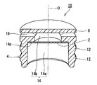
- FIG. 2 is a perspective cross-sectional view of the ventilation member shown in FIG. 1 .
- FIG. 3A is a perspective cross-sectional view of a ventilation structure including the ventilation member shown in FIG. 1 .
- FIG. 3B is a perspective cross-sectional view of another ventilation structure including the ventilation member shown in FIG. 1 .
- FIG. 3C is a perspective cross-sectional view of a modified form of the ventilation structure shown in FIG. 3A .
- FIG. 4 is a longitudinal cross-sectional view showing a preferred dimensional relationship of the support body, the cover body, and the column portions.
- FIG. 5 is a perspective view of a modified form of the cover body.
- FIG. 6A is a perspective view of the ventilation member without the cover body.
- FIG. 6B is a perspective view of a modified form of the column portion.
- FIG. 7 is a cross-sectional view showing a method for molding a main body of the ventilation member shown in FIG. 1 .
- FIG. 8A is a longitudinal cross-sectional view of a ventilation member according to a first modification.
- FIG. 8B is a longitudinal cross-sectional view of a ventilation member according to a second modification.
- FIG. 8C is a longitudinal cross-sectional view of a ventilation member according to a third modification.
- FIG. 9 is a longitudinal cross-sectional view of a ventilation member according to a fourth modification.
- FIG. 10 is a cross-sectional view showing a method for molding a main body of the ventilation member shown in FIG. 9 .
- FIG. 11 is a top view of a support member shown in FIG. 9 .
- a ventilation member 10 of the present embodiment includes an air-permeable membrane 2 , a support body 4 , a cover body 6 , and column portions 8 .
- the support body 4 , the cover body 6 , and the column portions 8 form a main body 11 .
- a first ventilation structure 100 is composed of a housing 20 having an opening portion 22 and the ventilation member 10 attached to the opening portion 22 .
- a second ventilation structure 102 is composed of the housing 20 having an opening portion 24 and the ventilation member 10 attached to the opening portion 24 .
- the ventilation member 10 is configured to be attachable to the housing 20 having the opening portion 22 or 24 for ventilation.
- the housing 20 has an interior space 23 that requires ventilation.
- the ventilation member 10 can prevent foreign substances such as water droplets from entering the housing 20 . Air can flow between the interior space 23 and the exterior space 25 through the air-permeable membrane 2 . Therefore, the pressure in the interior space 23 of the housing 20 is maintained equal to that in the exterior space 25 thereof.
- Examples of the housing 20 include automotive ECU (electronic control unit) box and lamp box.
- FIG. 3A and FIG. 3B each show only a part of the housing 20 .
- the opening portion 22 is a nozzle opening portion 22 projecting from the surface of the housing 20 .
- the opening portion 24 is a recess opening portion 24 recessed from the surface of the housing 20 .
- the ventilation member 10 is a ventilation member attachable to a plurality of different types of housings 20 each having the opening portion 22 in the form of a boss or the opening portion 24 in the form of a countersink.
- the detailed structure of the ventilation member 10 is described with reference to FIG. 1 and FIG. 2 .
- the support body 4 has a cylindrical overall shape.
- the support body 4 has a through hole 14 serving as an air passage between the interior space 23 and the exterior space 25 of the housing 20 .
- the through hole 14 includes a first portion 14 a and a second portion 14 b .
- the first portion 14 a is a portion into which the nozzle opening portion 22 ( FIG. 3A ) of the housing 20 is to be inserted and has a relatively large inner diameter D1.
- the second portion 14 b is a portion formed coaxially with the first portion 14 a and has a relatively small inner diameter D2.
- the first portion 14 a and the second portion 14 b communicate with each other when the air-permeable membrane 2 is removed.
- the difference (D1 ⁇ D2) between the inner diameter D1 of the first portion 14 a and the inner diameter D2 of the second portion 14 b can be adjusted to, for example, a range of 1.6 mm or more (i.e., 0.8 mm or more in terms of the difference in the radius (D1 ⁇ D2)/2).
- the support body 4 further has an annular flat surface 14 p formed at the boundary between the first portion 14 a and the second portion 14 b .
- the difference between the inner diameter D1 of the first portion 14 a and the inner diameter D2 of the second portion 14 b forms the flat surface 14 p inside the through hole 14 .
- the through hole 14 is closed by the air-permeable membrane 2 placed on the annular flat surface 14 p at the boundary between the first portion 14 a and the second portion 14 b . With this configuration, it is possible to reliably protect the air-permeable membrane 2 .
- the ventilation member 10 is attached to the housing 20 by fitting the support body 4 onto the nozzle opening portion 22 so that the inner peripheral surface of the support body 4 in the first portion 14 a is in close contact with the outer peripheral surface of the nozzle opening portion 22 .
- the nozzle opening portion 22 has an outer diameter approximately equal to the inner diameter D1 of the first portion 14 a . Therefore, the depth of insertion of the nozzle opening portion 22 is limited by a step (flat surface 14 p ) formed at the boundary between the first portion 14 a and the second portion 14 b . As a result, it is possible to prevent the nozzle opening portion 22 from being inserted too deeply and damaging the air-permeable membrane 2 .
- An annular ridge portion 12 is formed on the outer peripheral surface of the support body 4 along the circumferential direction of the support body 4 .
- the ventilation member 10 is attached to the housing 20 by fitting the support body 4 into the recess opening portion 24 so that the outer peripheral surface of the support body 4 in the ridge portion 12 is in close contact with the inner peripheral surface of the recess opening portion 24 .
- the elastic force of the support body 4 can be reliably applied to the recess opening portion 22 . As a result, it is possible to prevent detachment of the ventilation member 10 from the housing 20 .
- the ridge portion 12 is formed around the entire circumference (360 degrees) of the support body 4 .
- the cross section of the support body 4 has a circular outline when observed at the position of the ridge portion 12 . Therefore, when the ventilation member 10 is fitted into the recess opening portion 24 , no gap is formed between the support body 4 and the recess opening portion 24 . This means that the ridge portion 12 has a high sealing effect.
- a plurality of ridge portions 12 are formed in the height direction parallel to the central axis O of the through hole 14 . Specifically, two ridge portions 12 are provided in the height direction.
- the ridge portion 12 is located at least on the side of the first portion 14 a with respect to the boundary (flat surface 14 p ) between the first portion 14 a and the second portion 14 b .
- the two ridge portions 12 are formed concentrically in the height direction and are formed at positions corresponding to the first portion 14 a . With this configuration, it is possible to reliably fit the support body 4 into the recess opening portion 24 .
- the first portion 14 a in the height direction parallel to the central axis O of the through hole 14 , the first portion 14 a is sufficiently longer than the second portion 14 b . Specifically, the first portion 14 a has a length long enough to form two ridge portions 12 at positions corresponding to the first portion 14 a . When the first portion 14 a is sufficiently long, it is possible to provide a sufficiently long sealing length between the support body 4 and the nozzle opening portion 22 or the recess opening portion 24 .
- an annular ridge portion 13 may be formed on the inner peripheral surface of the support body 4 .
- the ridge portion 13 projecting toward the central axis O of the through hole 14 can be formed in the first portion 14 a of the through hole 14 .
- the cover body 6 is provided at a position facing the air-permeable membrane 2 so as to protect the air-permeable membrane 2 .
- the cover body 6 has a circular shape in a plane view, and has an outer diameter approximately equal to that of the support body 4 .
- a gap 16 serving as an air passage communicating with the second portion 14 b of the through hole 14 is formed between the lower surface of the cover body 6 and the upper surface of the support body 4 .
- the upper surface of the support body 4 is formed of the open end face of the second portion 14 b of the through hole 14 .
- the column portions 8 are provided between the support body 4 and the cover body 6 , and are formed integrally with both the support body 4 and the cover body 6 so as to fix the cover body 6 to the support body 4 . That is, the column portions 8 each extend from the upper surface of the support body 4 toward the lower surface of the cover body 6 . These column portions 8 have the following effects. Since the support body 4 , the cover body 6 , and the column portions 8 are formed as a single structure, the elastic force applied to the opening portion 22 or 24 is increased when the ventilation member 10 is attached to the housing 20 . Therefore, it is possible to reliably prevent detachment of the ventilation member 10 from the housing 20 .
- the air-permeable membrane 2 can be fully protected when the ventilation member 10 is configured so as to make the air-permeable membrane 2 invisible through the gap 16 .
- the length (height) of the column portion 8 in the height direction parallel to the central axis O is adjusted to a length long enough to form the gap 16 .
- the height of the column portion 8 is determined in accordance with the outer diameter of the cover body 6 and the inner diameter of the second portion 14 b of the through hole 14 in order to prevent direct exposure of the air-permeable membrane 2 to water jets when the water jets are directed obliquely toward the gap 16 .
- the dimensions of the support body 4 , the cover body 6 , and the column portion 8 can be adjusted so as to prevent a straight line L passing through the outer edge P of the lower surface of the cover body 6 and the inner edge Q of the open end face of the through hole 14 from intersecting the air-permeable membrane 2 in the longitudinal cross-section of the ventilation member 10 including the central axis O, as shown in FIG. 4 .
- this configuration it is possible to fully protect the air-permeable membrane 2 from foreign substances.
- a cover body 19 having a larger outer diameter than the outer diameter of the support body 4 may be provided.
- the straight line L shown in FIG. 4 becomes more horizontal (the acute angle formed between the straight line L and the central axis O increases).
- the almost horizontal straight line L makes it possible to prevent direct application of external water pressure to the membrane while keeping the dimensions of other components and spaces, such as the outer diameter of the support body 4 , the height of the gap 16 , and the height and diameter of the second portion 14 b , constant.
- the cover body 19 includes an outer peripheral portion 19 t projecting outwardly beyond the outer peripheral surface of the support body 4 in the horizontal direction perpendicular to the central axis O.
- This cover body 19 can reliably prevent entry of foreign substances into the gap 16 , for example, when automotive oil is dropped from above, and therefore can further enhance the function of protecting the air-permeable membrane 2 .
- the width PT of the outer peripheral portion 19 t projecting outwardly beyond the outer peripheral surface of the support body 4 is preferably, for example, 2 mm or more (4 mm or more in terms of the value obtained by subtracting the outer diameter of the support body 4 from the outer diameter of the cover body 19 ).
- the upper limit of the projecting width PT is not particularly limited, but it is preferably, for example, 4 mm or less.
- FIG. 6A is a perspective view of the ventilation member 10 without the cover body 6 .
- the column portions 8 are located on the annular open end face 141 of the second portion 14 b of the through hole 14 .
- a plurality of column portions 8 are provided at regular angular intervals on the open end face 141 .
- four column portions 8 are provided at angular intervals of 90 degrees on the open end face 141 .
- the plurality of column portions 8 can more reliably prevent detachment of the ventilation member 10 from the housing 20 . It should be understood that the column portion 8 may be provided at only one position on the open end face 141 .
- a column portion 18 structured as shown in FIG. 6B may be provided.
- the column portion 18 is located on the annular open end face 141 of the second portion 14 b of the through hole 14 .
- the column portion 18 has a bridge shape extending from a first position on the open end face 141 of the second portion 14 b to a second position on the open end face 141 of the second portion 14 b so that the opening of the second portion 14 b is divided into two or more sections by the column portion 18 .
- the “bridge shape” of the column portion 18 is composed of bridge portions intersecting each other, and more specifically, two bridge portions form a cross shape.
- the bridge shape of the column portion 18 may consist of one bridge portion, but preferably it is composed of two or more bridge portions.
- the bridge-shaped column portion 18 increases the area of the junction between the support body 4 and the cover body 6 , and when the ventilation member 10 is attached to the housing 20 , a compressive load is applied uniformly in the circumferential direction of the support body 4 . As a result, the compressive stress generated in the support body 4 is relaxed, and the effect of preventing detachment of the ventilation member 10 from the housing 20 is further enhanced.
- the main body 11 (the support body 4 , the cover body 6 , and the column portions 8 ) is made of an elastomer.
- the ventilation member 10 can be attached to the housing 20 by the elastic force of the main body 11 .
- a thermoplastic elastomer can be suitably used.
- rubber materials such as NBR (nitrile butadiene rubber), EPDM (ethylene propylene diene monomer rubber), silicone rubber, fluorine rubber, acrylic rubber, and hydrogenated nitrile rubber may be used as the materials for the main body 11 .
- the main body 11 may be made of a non-elastomeric thermoplastic resin.
- a thermoplastic resin include polyamide (PA), polyethylene terephthalate (PET), polybutylene terephthalate (PBT), polyphenylene sulfide (PPS), polycarbonate (PC), and polypropylene (PP). These thermoplastic resins have excellent moldability and weldability.
- the structure and material of the air-permeable membrane 2 are not particularly limited. Any membrane can be used as long as it has the properties of allowing gases to pass therethrough and preventing liquids from passing therethrough.
- the air-permeable membrane 2 may have a membrane main body and a reinforcing member laminated on the membrane main body.
- a porous membrane made of a resin such as fluorine resin or polyolefin can be used for the membrane main body.
- a porous resin membrane having an average pore diameter of 0.01 to 10 ⁇ m can be used as the membrane main body.
- the membrane main body may be subjected to liquid-repellent treatments such as an oil-repellent treatment and a water-repellent treatment. These liquid-repellent treatments can be performed by applying a substance having a low surface tension to the membrane main body, followed by drying and then curing. Any liquid-repellent agent can be used for the liquid-repellent treatment as long as a coating film having a lower surface tension than that of the membrane main body can be formed using the agent.
- a liquid-repellent agent containing a polymer having a perfluoroalkyl group can be suitably used.
- the liquid-repellent agent is applied to the membrane main body by a known technique such as impregnation or spraying.
- fluorine resin suitable for use as the membrane main body examples include polytetrafluoroethylene (PTFE), polychlorotrifluoroethylene, tetrafluoroethylene-hexafluoropropylene copolymer, and tetrafluoroethylene-ethylene copolymer.
- PTFE polytetrafluoroethylene
- polychlorotrifluoroethylene examples include homopolymers and copolymers of monomers such as ethylene, propylene, and 4-methylpentene-1,1 butene.
- Porous nanofiber film materials containing polyacrylonitrile, nylon, or polylactic acid may also be used.
- PTFE is preferred because it has not only high air permeability per unit area but also high ability to prevent foreign substances from entering the housing.
- Porous PTFE membranes can be produced by known molding techniques such as stretching and extraction.
- the reinforcing member can be a member made of a resin such as polyester, polyethylene, or aramid.
- the form of the reinforcing member is not particularly limited as long as the air permeability of the air-permeable membrane 2 can be maintained.
- the form of the reinforcing member is a woven fabric, a nonwoven fabric, a net, a mesh, a sponge, a foam, or a porous material.
- the membrane main body and the reinforcing member may be laminated together by heat lamination, heat welding, or ultrasonic welding, or with an adhesive.
- the thickness of the air-permeable membrane 2 is, for example, in the range of 1 ⁇ m to 5 mm, in view of the strength and the ease of fixing to the support body 4 .
- the air permeability of the air-permeable membrane 2 is, for example, in the range of 0.1 to 300 sec/100 cm 3 in terms of Gurley Number obtained by the Gurley test method specified in JIS (Japanese Industrial Standards) P 8117.
- the water entry pressure of the air-permeable membrane 2 is, for example, 1.0 kPa or more.
- the main body 11 of the ventilation member 10 can be produced by injection molding using a split mold unit 30 .
- the split mold unit 30 includes an upper mold 31 , a lower mold 32 , and a plurality of slide molds 33 .
- the main body 11 can be formed of a single component and therefore the production cost of the ventilation member 10 can be reduced.
- the life of the split mold unit 30 can be extended.
- a ventilation member 10 A according to the first modification includes an air-permeable membrane unit 5 .
- the ventilation member 10 A is the same as the ventilation member 10 described with reference to FIG. 1 to FIG. 7 , as indicated by the same reference numerals, except for the air-permeable membrane unit 5 .
- the air-permeable membrane unit 5 includes the air-permeable membrane 2 and a support member 3 .
- the support member 3 according to the first to third modifications is an annular member and is also referred to as a ring member hereinafter.
- the ring member 3 constitutes a part of the support body 4 in the ventilation member 10 A.
- the air-permeable membrane 2 is fixed to the ring member 3 by a method such as bonding or welding.
- the material of the ring member 3 is not particularly limited, and it is, for example, a resin or a metal.
- the inner diameter of the ring member 3 is, for example, larger than the inner diameter of the second portion 14 b of the through hole 14 and smaller than the inner diameter of the first portion 14 a of the through hole 14 .
- the outer diameter of the ring member 3 is approximately equal to the inner diameter of the first portion 14 a . Since the support body 4 is made of an elastomer, the air-permeable membrane unit 5 can be fixed into the through hole 14 by the elastic force of the support body 4 . More specifically, the air-permeable membrane unit 5 is disposed inside the through hole 14 so that the air-permeable membrane unit 5 is placed on (is in contact with) the annular flat surface 14 p . Thereby, the through hole 14 is closed by the air-permeable membrane 2 . The use of the air-permeable membrane unit 5 makes it possible to eliminate the difficulty of bonding or welding the air-permeable membrane 2 directly to the flat surface 14 p .
- the nozzle opening portion 22 of the housing 20 is not in contact with the air-permeable membrane 2 .
- the air-permeable membrane 2 can be prevented from being damaged by the nozzle opening portion 22 .
- the air-permeable membrane unit 5 may be bonded or welded to the flat surface 14 p.
- a ventilation member 10 B according to the second modification includes an air-permeable membrane unit 35 .
- the ventilation member 10 B is the same as the ventilation member 10 described with reference to FIG. 1 to FIG. 7 , as indicated by the same reference numerals, except for the air-permeable membrane unit 35 .
- the air-permeable membrane unit 35 is a member similar to the air-permeable membrane unit 5 described in the first modification. More specifically, the air-permeable membrane unit 35 includes two air-permeable membranes 2 and the ring member 3 . The air-permeable membranes 2 are fixed to both surfaces of the ring member 3 by a method such as bonding or welding. Thus, the air-permeable membrane unit 35 has a double membrane structure.
- the air-permeable membrane unit 35 further includes a buffer space 3 h enclosed by the two air-permeable membranes 2 .
- the buffer space 3 h is a space corresponding to the through hole of the ring member 3 . According to the ventilation member 10 B, it is possible to more reliably prevent foreign substances from entering the housing 20 .
- the function of the ventilation member 10 B is maintained by the other air-permeable membrane 2 .
- a ventilation member 10 C according to the third modification includes an air-permeable membrane unit 45 .
- the ventilation member 10 C is the same as the ventilation member 10 described with reference to FIG. 1 to FIG. 7 , as indicated by the same reference numerals, except for the air-permeable membrane unit 45 .
- the air-permeable membrane unit 45 includes the air-permeable membrane 2 and a ring member 9 .
- the air-permeable membrane unit 45 is also a member similar to the air-permeable membrane unit 5 described in the first modification.
- the ring member 9 is composed of a first portion 9 a having a relatively large outer diameter and a second portion 9 b having a relatively small outer diameter.
- the inner diameter of the first portion 9 a may be equal to or different from that of the second portion 9 b .
- the air-permeable membrane 2 is disposed on the second portion 9 b so as to close the through hole of the ring member 9 .
- the air-permeable membrane unit 45 is disposed inside the support body 4 so that the second portion 9 b of the ring member 9 is located in the second portion 14 b of the through hole 14 and the first portion 9 a of the ring member 9 is located in the first portion 14 a .
- the air-permeable membrane unit 45 is also fixed into the through hole 14 by the elastic force of the support body 4 .
- the length of the second portion 9 b of the ring member 9 is approximately equal to the length of the second portion 14 b of the through hole 14 .
- the air-permeable membrane 2 can be disposed on approximately the same level as the open end face 141 of the through hole 14 .
- a ventilation member 10 D according to the fourth modification includes an air-permeable membrane unit 15 .
- the ventilation member 10 D is the same as the ventilation member 10 described with reference to FIG. 1 to FIG. 7 , as indicated by the same reference numerals, except for the air-permeable membrane unit 15 .
- the air-permeable membrane unit 15 includes the air-permeable membrane 2 and a support member 7 .
- the support member 7 of the fourth modification includes a ring portion 7 a and a bridge portion 7 b that bridges a first part and a second part of the ring portion 7 a and passes through the central axis of the ring portion 7 a .
- the bridge portion 7 b is composed of two bridge portions intersecting each other in a plane view of the surface that supports the air-permeable membrane 2 (in the state shown in FIG. 11 ).
- the bridge portion 7 b in the fourth modification is in contact with the ring portion 7 a on the inner peripheral surface thereof.
- the ring portion 7 a and the bridge portion 7 b of the support member 7 support the air-permeable membrane 2 from the housing-side surfaces thereof.
- the air-permeable membrane 2 is located at the boundary between the first portion 14 a and the second portion 14 b of the through hole 14 .
- the ventilation member 10 D includes the bridge-shaped column portion 18 (see FIG. 6B ) between the cover body 6 and the support body 4 .
- the bridge portion 7 b of the support member 7 extends along the column portion 18 so that the entire surface of the column portion 18 on the air-permeable membrane 2 side is covered by the support body 4 .
- the bridge portion 7 b also has a cross shape so as to conform to the cross shape of the column portion 18 in a plane view.
- the second portion 14 b of the through hole 14 of the ventilation member 10 D is formed between the inner periphery of the ring portion 7 a of the support member 7 and the bridge portion 7 b thereof and divided into two or more sections by the bridge portion 7 b .
- the first portion 14 a of the through hole 14 has a diameter defined by the inner periphery of the support body 4 .
- the radially inwardly projecting portion that partially reduces the diameter of the through hole 14 consists of the support member 7 , unlike the ventilation members as described above.
- the rest of the support body 4 except for the support member 7 has a cylindrical inner peripheral surface.
- the ventilation member 10 D is particularly suitable for production by so-called insert molding.
- FIG. 10 shows an example of a split mold unit 50 suitable for this insert molding.
- the split mold unit 50 is composed of an upper mold 51 , a lower mold 52 , and a plurality of slide modes 53 .
- the air-permeable membrane unit 15 is placed inside the split mold unit 50 and then a resin is injected into the cavity of the mold.
- the ventilation member 10 D including the air-permeable membrane 2 can be obtained.
- the bridge portion 7 b of the air-permeable membrane unit 15 blocks the flow of the resin, which is injected into a space in which the column portion 18 is to be formed, toward the air-permeable membrane 2 so as to prevent the injected resin from contacting the air-permeable membrane 2 .
- the entire air-permeable membrane 2 side surface of the bridge-shaped column portion 18 is covered by the support body 4 , more specifically, by the support body 4 composed of the injected resin and the support member 7 .
- the support members 3 , 7 , and 9 of the air-permeable membrane units shown in the first to fourth modifications may each be made of an elastomer, but may be made of a non-elastomeric resin or a metal.
- the rest of the support body 4 except for the support member, the cover body 6 , and the column portion 18 each be made of an elastomer so as to configure a ventilation member adapted to be attached by the elastic force of the elastomer.
- the ventilation member can be configured such that the rest of the support body 4 made of the elastomer and the column portion 18 are connected together.
- the portion made of the elastomer (the rest of the support body 4 , the cover body 6 , and the column portion 18 ) are integrally formed. Therefore, the stiffness of the ventilation member increases, and thus when it is press-fitted into the opening portion of the housing, its resistance to detachment from the housing improves.
- the ventilation member of the present invention can be used in housings for automotive components such as lamps, motors, sensors, switches, ECUs, and gear boxes. Furthermore, the ventilation member of the present invention can be used not only for the automobile components but also in electrical appliances such as mobile communication devices, cameras, electric shavers, electric toothbrushes, and washing machines (for example, humidity sensors in washing machines).
Landscapes
- Engineering & Computer Science (AREA)
- General Engineering & Computer Science (AREA)
- Chemical & Material Sciences (AREA)
- Combustion & Propulsion (AREA)
- Mechanical Engineering (AREA)
- Microelectronics & Electronic Packaging (AREA)
- Analytical Chemistry (AREA)
- General Chemical & Material Sciences (AREA)
- Oil, Petroleum & Natural Gas (AREA)
- Chemical Kinetics & Catalysis (AREA)
- Arrangement Of Elements, Cooling, Sealing, Or The Like Of Lighting Devices (AREA)
- Non-Portable Lighting Devices Or Systems Thereof (AREA)
Applications Claiming Priority (3)
| Application Number | Priority Date | Filing Date | Title |
|---|---|---|---|
| JP2011258507A JP5792603B2 (ja) | 2011-11-28 | 2011-11-28 | 通気部材 |
| JP2011-258507 | 2011-11-28 | ||
| PCT/JP2012/007485 WO2013080494A1 (ja) | 2011-11-28 | 2012-11-21 | 通気部材 |
Publications (2)
| Publication Number | Publication Date |
|---|---|
| US20140318374A1 US20140318374A1 (en) | 2014-10-30 |
| US9255719B2 true US9255719B2 (en) | 2016-02-09 |
Family
ID=48534990
Family Applications (1)
| Application Number | Title | Priority Date | Filing Date |
|---|---|---|---|
| US14/360,539 Active US9255719B2 (en) | 2011-11-28 | 2012-11-21 | Ventilation member |
Country Status (6)
| Country | Link |
|---|---|
| US (1) | US9255719B2 (de) |
| EP (1) | EP2787277B1 (de) |
| JP (1) | JP5792603B2 (de) |
| KR (1) | KR101580756B1 (de) |
| CN (1) | CN103958964B (de) |
| WO (1) | WO2013080494A1 (de) |
Cited By (4)
| Publication number | Priority date | Publication date | Assignee | Title |
|---|---|---|---|---|
| US20160113131A1 (en) * | 2014-10-17 | 2016-04-21 | Garmin International, Inc. | Vent assembly for an electronic device enclosure |
| US20190331312A1 (en) * | 2018-04-25 | 2019-10-31 | Jute Industrial Co., Ltd. | Breathable element for lighting of vehicle |
| WO2019224453A1 (fr) | 2018-05-22 | 2019-11-28 | A. Raymond Et Cie | Boitier de protection d'un dispositif electronique |
| US11083097B2 (en) * | 2015-08-05 | 2021-08-03 | Vitesco Technologies GmbH | Pressure-equalizing element and housing containing same |
Families Citing this family (21)
| Publication number | Priority date | Publication date | Assignee | Title |
|---|---|---|---|---|
| JP5622369B2 (ja) * | 2009-07-15 | 2014-11-12 | 日本ゴア株式会社 | 通気栓 |
| JP6105887B2 (ja) * | 2012-09-28 | 2017-03-29 | 日立オートモティブシステムズ株式会社 | 電子制御装置 |
| JP6150578B2 (ja) * | 2013-03-26 | 2017-06-21 | 日東電工株式会社 | 通気部材 |
| JP6167658B2 (ja) * | 2013-05-13 | 2017-07-26 | 株式会社デンソー | 通気部材取付冶具および電子装置の製造方法 |
| US9398710B2 (en) * | 2014-08-07 | 2016-07-19 | Continental Automotive Gmbh | Enclosure for an electronic control unit and electronic control unit |
| JP2016098882A (ja) * | 2014-11-19 | 2016-05-30 | 日東電工株式会社 | 駆動装置、通気部材 |
| KR101626774B1 (ko) * | 2015-05-21 | 2016-06-02 | 박용국 | 차량 램프 제습장치 |
| EP3098028A1 (de) * | 2015-05-26 | 2016-11-30 | HILTI Aktiengesellschaft | Handwerkzeuggetriebeverschluss und handwerkzeugmaschine |
| JP6721978B2 (ja) * | 2015-12-15 | 2020-07-15 | 日東電工株式会社 | 通気部材、ランプ |
| KR102515289B1 (ko) * | 2016-01-08 | 2023-03-29 | 엘지이노텍 주식회사 | 전자 디바이스용 마개 |
| US10137665B2 (en) * | 2016-01-14 | 2018-11-27 | Tokyo Ohka Kogyo Co., Ltd. | Method for manufacturing laminate, and laminate |
| JP7034581B2 (ja) * | 2016-08-30 | 2022-03-14 | 日東電工株式会社 | 通気部材 |
| CN106764987A (zh) * | 2016-12-01 | 2017-05-31 | 天津得丰光合科技有限公司 | 一种车灯通气口连接结构 |
| JP7177083B2 (ja) * | 2017-12-07 | 2022-11-22 | 日東電工株式会社 | 支持体の製造方法 |
| CN111316763B (zh) * | 2018-10-11 | 2023-03-07 | 日东电工株式会社 | 通气组件及通气壳体 |
| CN209431372U (zh) * | 2018-12-07 | 2019-09-24 | 欧普照明股份有限公司 | 一种用于灯具的呼吸结构和灯具 |
| JP7378967B2 (ja) * | 2019-06-07 | 2023-11-14 | 日東電工株式会社 | 通気部品 |
| DE102019211825A1 (de) * | 2019-07-01 | 2021-01-07 | Vitesco Technologies Germany Gmbh | Vorrichtung zum Druckausgleich eines Gehäuses |
| JP6762630B1 (ja) * | 2020-01-08 | 2020-09-30 | 東和化学株式会社 | 通気防水構造体 |
| JP7484335B2 (ja) * | 2020-03-31 | 2024-05-16 | 岩崎電気株式会社 | 照明器具 |
| CN116887952A (zh) * | 2021-03-15 | 2023-10-13 | Abb瑞士股份有限公司 | 泄压部件、齿轮箱和机器人 |
Citations (16)
| Publication number | Priority date | Publication date | Assignee | Title |
|---|---|---|---|---|
| US5522769A (en) * | 1994-11-17 | 1996-06-04 | W. L. Gore & Associates, Inc. | Gas-permeable, liquid-impermeable vent cover |
| US5914415A (en) * | 1996-09-18 | 1999-06-22 | Nitto Denko Corporation | Vent filter member |
| JP2001143524A (ja) | 1999-11-18 | 2001-05-25 | Nitto Denko Corp | 通気キャップおよびそれを用いた屋外用ランプ,自動車用ランプならびに自動車用電装部品 |
| US20020090506A1 (en) * | 2000-10-28 | 2002-07-11 | Claudia Protzner | EMI protective venting element for electronic housings |
| DE202006008917U1 (de) | 2006-06-02 | 2006-08-17 | Oxyphen Gmbh Dresden | Luftdurchlässiges Verschlusselement für geschlossene Geräte |
| JP2007087929A (ja) | 2005-08-24 | 2007-04-05 | Nitto Denko Corp | 通気部材 |
| JP2007186189A (ja) | 2005-12-14 | 2007-07-26 | Nitto Denko Corp | 通気部材および通気構造 |
| EP1835227A1 (de) | 2004-12-07 | 2007-09-19 | Nitto Denko Corporation | Durchlässiges glied, das durchlässige glied verwendendes durchlässiges gehäuse und elektrisches teil |
| EP1884695A1 (de) | 2005-05-18 | 2008-02-06 | Nitto Denko Corporation | Gasdurchlässiges glied und dieses verwendendes gasdurchlässiges gehäuse |
| US20090047890A1 (en) * | 2005-11-17 | 2009-02-19 | Nitto Denko Corporation | Vent Member |
| US20100227544A1 (en) * | 2005-12-14 | 2010-09-09 | Nitto Denko Corporation | Vent Member and Vent Structure |
| WO2010143624A1 (ja) | 2009-06-12 | 2010-12-16 | ジャパンゴアテックス株式会社 | 通気栓及び通気栓の検査方法 |
| JP2011023206A (ja) | 2009-07-15 | 2011-02-03 | Japan Gore Tex Inc | 通気栓 |
| US20130055898A1 (en) * | 2011-05-19 | 2013-03-07 | Nitto Denko Corporation | Vent structure |
| US20140137739A1 (en) * | 2012-11-20 | 2014-05-22 | Nitto Denko Corporation | Ventilation member |
| US20140290489A1 (en) * | 2013-03-26 | 2014-10-02 | Nitto Denko Corporation | Ventilation member |
Family Cites Families (1)
| Publication number | Priority date | Publication date | Assignee | Title |
|---|---|---|---|---|
| CN100587332C (zh) * | 2005-08-24 | 2010-02-03 | 日东电工株式会社 | 透气构件 |
-
2011
- 2011-11-28 JP JP2011258507A patent/JP5792603B2/ja active Active
-
2012
- 2012-11-21 US US14/360,539 patent/US9255719B2/en active Active
- 2012-11-21 WO PCT/JP2012/007485 patent/WO2013080494A1/ja active Application Filing
- 2012-11-21 KR KR1020147017454A patent/KR101580756B1/ko active IP Right Grant
- 2012-11-21 CN CN201280058515.6A patent/CN103958964B/zh active Active
- 2012-11-21 EP EP12852582.1A patent/EP2787277B1/de active Active
Patent Citations (20)
| Publication number | Priority date | Publication date | Assignee | Title |
|---|---|---|---|---|
| US5522769A (en) * | 1994-11-17 | 1996-06-04 | W. L. Gore & Associates, Inc. | Gas-permeable, liquid-impermeable vent cover |
| US5914415A (en) * | 1996-09-18 | 1999-06-22 | Nitto Denko Corporation | Vent filter member |
| JP2001143524A (ja) | 1999-11-18 | 2001-05-25 | Nitto Denko Corp | 通気キャップおよびそれを用いた屋外用ランプ,自動車用ランプならびに自動車用電装部品 |
| US6364924B1 (en) | 1999-11-18 | 2002-04-02 | Nitto Denko Corporation | Air permeable cap and outdoor lamp, automobile lamp and electrical component comprising same |
| US20020090506A1 (en) * | 2000-10-28 | 2002-07-11 | Claudia Protzner | EMI protective venting element for electronic housings |
| EP1835227A1 (de) | 2004-12-07 | 2007-09-19 | Nitto Denko Corporation | Durchlässiges glied, das durchlässige glied verwendendes durchlässiges gehäuse und elektrisches teil |
| EP1884695A1 (de) | 2005-05-18 | 2008-02-06 | Nitto Denko Corporation | Gasdurchlässiges glied und dieses verwendendes gasdurchlässiges gehäuse |
| JP2007087929A (ja) | 2005-08-24 | 2007-04-05 | Nitto Denko Corp | 通気部材 |
| US20090084078A1 (en) | 2005-08-24 | 2009-04-02 | Nitto Denko Corporation | Ventilation member |
| US20090047890A1 (en) * | 2005-11-17 | 2009-02-19 | Nitto Denko Corporation | Vent Member |
| US20100227544A1 (en) * | 2005-12-14 | 2010-09-09 | Nitto Denko Corporation | Vent Member and Vent Structure |
| JP2007186189A (ja) | 2005-12-14 | 2007-07-26 | Nitto Denko Corp | 通気部材および通気構造 |
| DE202006008917U1 (de) | 2006-06-02 | 2006-08-17 | Oxyphen Gmbh Dresden | Luftdurchlässiges Verschlusselement für geschlossene Geräte |
| WO2010143624A1 (ja) | 2009-06-12 | 2010-12-16 | ジャパンゴアテックス株式会社 | 通気栓及び通気栓の検査方法 |
| JP2010286378A (ja) * | 2009-06-12 | 2010-12-24 | Japan Gore Tex Inc | 通気栓及び通気栓の検査方法 |
| JP2011023206A (ja) | 2009-07-15 | 2011-02-03 | Japan Gore Tex Inc | 通気栓 |
| US20120174789A1 (en) | 2009-07-15 | 2012-07-12 | W.L. Gore & Associates, Co., Ltd. | Vent Plug |
| US20130055898A1 (en) * | 2011-05-19 | 2013-03-07 | Nitto Denko Corporation | Vent structure |
| US20140137739A1 (en) * | 2012-11-20 | 2014-05-22 | Nitto Denko Corporation | Ventilation member |
| US20140290489A1 (en) * | 2013-03-26 | 2014-10-02 | Nitto Denko Corporation | Ventilation member |
Non-Patent Citations (1)
| Title |
|---|
| Extended European Search Report for corresponding European Patent Application No. 12852582.1, Nov. 23, 2015, 7 pages. |
Cited By (5)
| Publication number | Priority date | Publication date | Assignee | Title |
|---|---|---|---|---|
| US20160113131A1 (en) * | 2014-10-17 | 2016-04-21 | Garmin International, Inc. | Vent assembly for an electronic device enclosure |
| US11083097B2 (en) * | 2015-08-05 | 2021-08-03 | Vitesco Technologies GmbH | Pressure-equalizing element and housing containing same |
| US20190331312A1 (en) * | 2018-04-25 | 2019-10-31 | Jute Industrial Co., Ltd. | Breathable element for lighting of vehicle |
| WO2019224453A1 (fr) | 2018-05-22 | 2019-11-28 | A. Raymond Et Cie | Boitier de protection d'un dispositif electronique |
| US11415478B2 (en) | 2018-05-22 | 2022-08-16 | A. Raymond Et Cie | Protective housing for protecting an electronic device from environmental conditions |
Also Published As
| Publication number | Publication date |
|---|---|
| US20140318374A1 (en) | 2014-10-30 |
| EP2787277A1 (de) | 2014-10-08 |
| KR101580756B1 (ko) | 2015-12-28 |
| CN103958964A (zh) | 2014-07-30 |
| EP2787277A4 (de) | 2015-12-23 |
| KR20140099292A (ko) | 2014-08-11 |
| JP2013114829A (ja) | 2013-06-10 |
| CN103958964B (zh) | 2017-03-29 |
| WO2013080494A1 (ja) | 2013-06-06 |
| EP2787277B1 (de) | 2017-10-11 |
| JP5792603B2 (ja) | 2015-10-14 |
Similar Documents
| Publication | Publication Date | Title |
|---|---|---|
| US9255719B2 (en) | Ventilation member | |
| US8246726B2 (en) | Ventilation member | |
| JP4672530B2 (ja) | 通気部材 | |
| JP6130183B2 (ja) | 通気部材 | |
| KR101958036B1 (ko) | 통기 유닛 | |
| KR101958035B1 (ko) | 통기 유닛 | |
| JP6130182B2 (ja) | 通気部材 | |
| KR102686207B1 (ko) | 통기 부재, 램프 | |
| KR20010049300A (ko) | 통기성 캡과, 그것을 포함하는 옥외용 램프, 자동차용램프 및 자동차용 전장 부품 | |
| JP4498996B2 (ja) | 筐体の通気構造 | |
| WO2019135399A1 (ja) | 筐体キット及び通気部材 | |
| KR102674776B1 (ko) | 통기 하우징 | |
| KR20200002983A (ko) | 통기 부재 | |
| CN111492175B (zh) | 支承体的制造方法 | |
| JP5710359B2 (ja) | 通気部材 | |
| WO2021029386A1 (ja) | 通気構造 | |
| JP6121210B2 (ja) | 通気部材 | |
| KR102634104B1 (ko) | 통기 부품 | |
| KR102368493B1 (ko) | 차량용 통기부재 |
Legal Events
| Date | Code | Title | Description |
|---|---|---|---|
| AS | Assignment |
Owner name: NITTO DENKO CORPORATION, JAPAN Free format text: ASSIGNMENT OF ASSIGNORS INTEREST;ASSIGNOR:YANO, YOUZOU;REEL/FRAME:032959/0215 Effective date: 20140519 |
|
| STCF | Information on status: patent grant |
Free format text: PATENTED CASE |
|
| MAFP | Maintenance fee payment |
Free format text: PAYMENT OF MAINTENANCE FEE, 4TH YEAR, LARGE ENTITY (ORIGINAL EVENT CODE: M1551); ENTITY STATUS OF PATENT OWNER: LARGE ENTITY Year of fee payment: 4 |
|
| MAFP | Maintenance fee payment |
Free format text: PAYMENT OF MAINTENANCE FEE, 8TH YEAR, LARGE ENTITY (ORIGINAL EVENT CODE: M1552); ENTITY STATUS OF PATENT OWNER: LARGE ENTITY Year of fee payment: 8 |