US9246266B2 - Plug-connectable equipment combination - Google Patents
Plug-connectable equipment combination Download PDFInfo
- Publication number
- US9246266B2 US9246266B2 US14/277,864 US201414277864A US9246266B2 US 9246266 B2 US9246266 B2 US 9246266B2 US 201414277864 A US201414277864 A US 201414277864A US 9246266 B2 US9246266 B2 US 9246266B2
- Authority
- US
- United States
- Prior art keywords
- latching
- bedplate
- housing
- module
- plug
- Prior art date
- Legal status (The legal status is an assumption and is not a legal conclusion. Google has not performed a legal analysis and makes no representation as to the accuracy of the status listed.)
- Active
Links
- 230000013011 mating Effects 0.000 claims abstract description 25
- 238000003825 pressing Methods 0.000 description 3
- 230000000903 blocking effect Effects 0.000 description 2
- 238000000034 method Methods 0.000 description 2
- 238000005192 partition Methods 0.000 description 2
- 238000010276 construction Methods 0.000 description 1
- 230000000694 effects Effects 0.000 description 1
- 238000012986 modification Methods 0.000 description 1
- 230000004048 modification Effects 0.000 description 1
- 230000007704 transition Effects 0.000 description 1
Images


Classifications
-
- H—ELECTRICITY
- H01—ELECTRIC ELEMENTS
- H01R—ELECTRICALLY-CONDUCTIVE CONNECTIONS; STRUCTURAL ASSOCIATIONS OF A PLURALITY OF MUTUALLY-INSULATED ELECTRICAL CONNECTING ELEMENTS; COUPLING DEVICES; CURRENT COLLECTORS
- H01R13/00—Details of coupling devices of the kinds covered by groups H01R12/70 or H01R24/00 - H01R33/00
- H01R13/62—Means for facilitating engagement or disengagement of coupling parts or for holding them in engagement
- H01R13/627—Snap or like fastening
- H01R13/6271—Latching means integral with the housing
- H01R13/6272—Latching means integral with the housing comprising a single latching arm
-
- H—ELECTRICITY
- H01—ELECTRIC ELEMENTS
- H01R—ELECTRICALLY-CONDUCTIVE CONNECTIONS; STRUCTURAL ASSOCIATIONS OF A PLURALITY OF MUTUALLY-INSULATED ELECTRICAL CONNECTING ELEMENTS; COUPLING DEVICES; CURRENT COLLECTORS
- H01R9/00—Structural associations of a plurality of mutually-insulated electrical connecting elements, e.g. terminal strips or terminal blocks; Terminals or binding posts mounted upon a base or in a case; Bases therefor
- H01R9/22—Bases, e.g. strip, block, panel
- H01R9/24—Terminal blocks
- H01R9/26—Clip-on terminal blocks for side-by-side rail- or strip-mounting
- H01R9/2608—Fastening means for mounting on support rail or strip
-
- H—ELECTRICITY
- H01—ELECTRIC ELEMENTS
- H01R—ELECTRICALLY-CONDUCTIVE CONNECTIONS; STRUCTURAL ASSOCIATIONS OF A PLURALITY OF MUTUALLY-INSULATED ELECTRICAL CONNECTING ELEMENTS; COUPLING DEVICES; CURRENT COLLECTORS
- H01R9/00—Structural associations of a plurality of mutually-insulated electrical connecting elements, e.g. terminal strips or terminal blocks; Terminals or binding posts mounted upon a base or in a case; Bases therefor
- H01R9/22—Bases, e.g. strip, block, panel
- H01R9/24—Terminal blocks
- H01R9/2425—Structural association with built-in components
- H01R9/2441—Structural association with built-in components with built-in overvoltage protection
Definitions
- the invention relates to a pluggable device combination having a plug module and a device bedplate wherein a latching arm, which has a latching hooked formed as one piece on its end face, is connected to the latching connection of said device bedplate and to the plug module on the housing side, and said latching arm cooperates with a mating latch of the device bedplate for the purpose of forming a latching connection that can be detached by virtue of applying force.
- the plug module is in particular an overload safety switch.
- WO 95/12905 A1 describes a pluggable device combination having a latching connection between a plug module and a U-shaped sub-frame having latching lugs that are provided on opposite lying sides of the plug module and said latching lugs protrude towards the exterior and can latch with mating latches on the sub-frame.
- the respective latching lug is located on the side wall of the plug module on a snap arm that can be deformed in a resilient manner towards the interior and is formed as one piece on the plug module housing for the purpose of forming a hinged joint.
- the hinged joint is located on the underside of the plug module that is facing towards the base of the U-shaped sub-frame.
- the latching connection can be detached by virtue of applying pressure to an actuating protrusion on the snap arm.
- German published patent application DE 10 2006 033 274 A1 describes a pluggable device combination having a bedplate type U-shaped sub-frame for the purpose of receiving a plug module that receives an overvoltage safety element, wherein in turn latching means are provided that likewise comprise latching lugs on the two opposite-lying end faces of the plug modules and said latching lugs engage in each case in an associated undercut latching recess on the plug module.
- the plug module-side latching lugs are embodied in each case on a hinged joint that is pre-stressed, wherein the latching connection can be detached by virtue of applying pressure to the hinged joint on the end faces of the plug module.
- the application of pressure on an actuating surface that is facing towards a bedplate type sub-frame causes the latching lug to pivot towards the module housing in order to detach the two sided latching connections with the latching recesses of the device bedplate type sub-frame.
- a pluggable device combination comprising:
- the plug-connectible or pluggable device combination comprises a device bedplate and a plug module that receives safety switch elements, and a latching arm that extends in the direction towards the device bedplate and comprises a latching hook that is formed as one piece on the end face of said latching arm is connected to the module housing of said plug module.
- a latching arm that extends in the direction towards the device bedplate and comprises a latching hook that is formed as one piece on the end face of said latching arm is connected to the module housing of said plug module.
- the protrusion-like connecting site of said latching arm is located on one of the narrow sides of the module housing in the upper housing region that is lying remote from the device bedplate.
- the plug module sits in the device bedplate between plugging surfaces that laterally flank a bedplate base, wherein a mating latch that can latch with the latching hook of the plug module is formed as one piece only on one of the plugging surfaces for the purpose of forming a latching connection.
- a pivot site is formed between the housing-side connection of the latching arm and the latching hook of said latching arm so that a pivoting section of the latching arm is achieved between the pivot site and the latching hook and also an actuating section for the purpose of applying pressure is achieved on said pivoting section between the pivot site and the housing-side connection of the latching arm.
- the pivoting section of the latching arm pivots about the pivot site so that the latching connection is detached.
- the pivot site is embodied from a protrusion that is located on the rear side of the latching arm and is formed as one piece laterally on the module housing.
- This protrusion can be connected to the latching arm in particular as one piece.
- a pivot joint is formed by means of the protrusion that is formed as one piece on both the module housing and also the latching arm.
- the latching arm lies only on the protrusion without a material connection, a pivot point or rather a linear pivot is formed at this site.
- the latching arm is formed as one piece on the corresponding housing narrow side in such a manner that a housing chamber is formed between the latching arm and the housing narrow side.
- the bedplate-side mating latch protrudes in this housing chamber and into the chamber section that is located underneath the pivot site and faces the device bedplate for the purpose of producing the latching connection.
- the latching arm is bent in the region of the pivot site in such a manner that the pivoting section of the latching arm is spaced at a shorter distance from the module housing or rather from the side surface of said module housing than the actuating section of the latching arm.
- the outer contour of the latching arm and of the latching connection match the outer contour of the plug module in a particularly consistent manner.
- the device bedplate comprises in the bedplate itself contact elements that are connected in an electrically conductive manner to clamps that can be accessed from the exterior, and said contact elements can be accessed by way of the base of the device bedplate and correspond with contact elements that protrude out of the plug module on the base side.
- contact elements can be accessed by way of the base of the device bedplate and correspond with contact elements that protrude out of the plug module on the base side.
- five plug contact connections of this type are provided.
- the device combination comprises a plug coding arrangement between the plug module and the housing base.
- Said plug coding arrangement is formed in a suitable manner by means of plug module-side plug pockets and base-side hollow coding pins that engage in the plug pockets of the plug module in a positive-locking manner.
- the plug pockets comprise preferably pin-shaped coding elements that are formed for the purpose of forming a predetermined breaking point and that can be broken off individually.
- the corresponding bedplate-side hollow coding pins that protrude upwards out of the base of the device bedplate comprise in each case a hollow chamber that can be closed for coding purposes.
- coding elements that are provided can be plugged into the individual hollow coding pins.
- FIG. 1 illustrates a lateral view of a pluggable device combination having a device bedplate and a plug module
- FIG. 2 illustrates a view in an enlarged scale of the detail II from FIG. 1 with the individual latching site between the plug module and the device bedplate,
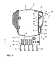
- FIG. 3 illustrates the plug module together with a module housing that is cut away in the region of a latching arm and comprises a pivot site protrusion that is formed on said module housing,
- FIG. 4 illustrates the plug module in an view in accordance with FIG. 3 together with a pivot joint formed on said plug module
- FIG. 5 illustrates a lateral view of the plug module with a view of the latching arm
- FIG. 6 illustrates the device bedplate with a view of its base having hollow coding pins that are formed as one piece on said base
- FIG. 7 illustrates the pluggable device combination in accordance with FIG. 1 in a partial sectional view with a view of contact elements that are inside the device.
- FIG. 1 there is shown a device combination 1 having a plug module 2 and a device bedplate 3 that comprises a U-shaped plugging region or section 4 having two plugging surfaces 4 b and 4 c that are laterally flanking the bedplate base 4 a .
- the plug module 2 is received by the plugging region 4 in a virtually positive-locking manner and said plug module lies with its plugging shaft (plugging region or section) 2 a on the one hand on the bedplate base 4 a and on the other hand on the side surface 4 b , 4 c .
- the plug module 2 comprises a module housing 5 having narrow or housing narrow sides 5 a and 5 b that lie opposite one another.
- a latching connection 6 is located only on one of the two narrow sides 5 b between the plug module 2 and the device bedplate 3 and the plug module 2 latches with the device bedplate 3 in a detachable manner by way of said latching connection.
- Holding or snap-action contours 7 a , 7 b are formed on the base-side on the device bedplate 3 for a cap rail assembly of the device combination.
- FIG. 2 illustrates a scaled-up view of area II of the latching connection 6 shown in FIG. 1 .
- the plug module 2 comprises on its housing narrow side 5 b a latching arm 8 that is involved in the latching connection 6 and said latching arm extends along the housing narrow side 5 b in the direction z towards the device bedplate 3 and supports on its free end a latching hook 8 a .
- the latching hook 8 a is arranged with its latching surface (not illustrated in detail) towards the module housing 5 and on the housing narrow side 5 b of said module housing towards a narrow-sided housing partition wall or 5 c that is subsequently described as an interior wall.
- a lower chamber section 9 a of a housing chamber 9 FIGS.
- a mating latch 10 protrudes into this lower chamber section 9 a of the housing chamber 9 with its mating latching hooks 10 b that are formed on the free end of a latching shaft 10 a.
- the mating latch 10 is formed on the bedplate side in the region of the plugging surface 4 b on the device bedplate 3 and extends so to speak in the direction z as an extension of the plugging surface 4 b .
- the mating latching hook 10 b of the mating latch 10 extends in turn with its non-illustrated mating latch surface from the module housing 5 and as a consequence from the plug module 2 towards the exterior in the direction x.
- the latching hook 8 a of the plug module-side latching arm 8 is located on the end of a pivoting section 8 c of the latching arm 8 , said end facing towards the device bedplate 3 .
- the plug module-side latching arm 8 is formed on the housing narrow side 5 b on the module housing 5 , wherein a corresponding connection or rather connection site 11 of the latching arm 8 is located on the housing narrow side 5 b in the region of the module upper face 2 b that is remote from the plugging shaft 2 a of the plug module 2 .
- a protrusion 12 that extends in the direction x and towards the latching arm 8 is formed on the interior wall 5 c of the housing narrow side 5 b of the module housing 5 .
- Said protrusion forms a pivot site for the purpose of pivoting the lower pivoting section 8 c of the latching arm 8 as a result of a force F that acts on said latching arm.
- the force F is applied manually onto an actuating section 8 d of the plug module-side latching arm 8 , said actuating section being connected to the pivoting section 8 c in the direction z.
- the pivot site 12 is located in the transition region between the actuating section 8 d and the pivoting section 8 c of the latching arm 8 .
- the pivoting section 8 c is—when seen in the direction z or rather in the longitudinal section of the latching arm 8 —shorter than the actuating section 8 d .
- the pivot site 12 is provided in the lower section half a of the longitudinal direction A that is formed between the housing-side connection 11 of the latching arm 8 and the latching hook 8 a of said latching arm, said lower section half facing towards the device bedplate 3 .
- the latching arm 8 lies on the protrusion 12 , whereby a point or linear pivot site is formed
- the protrusion 12 is also connected by means of a material connection to the latching arm 8 or rather to the rear face 8 b of said latching arm for the purpose of forming a pivot site in the form of a type of pivot joint and as a consequence, said protrusion is connected to the module housing 5 and to the interior wall 5 c of said housing module by way of this protrusion 12 .
- the pivot site 12 separates the housing chamber 9 that is formed between the latching arm 8 , or rather its rear face 8 b , and the housing narrow side 5 b , or rather its interior wall 5 c , into the lower chamber region 9 a , which is already described with reference to FIG. 2 , and an upper chamber region 9 b .
- said chamber region 9 b extends between the pivot site 12 and the connecting site 11 of the latching arm 8 on the module housing 5 .
- the latching arm 8 is bent in the region of the pivot site 12 , wherein a correspondingly curved or narrower contour 8 e is formed. As a consequence of this curved or narrower contour 8 e , the lower chamber section 9 a of the housing chamber 9 is restricted in comparison to the upper housing chamber 9 b in the direction x.
- the pivoting section 8 c of the latching arm 8 is consequently spaced at a shorter distance from the housing inner wall 5 c in comparison to its actuating section 8 d.
- the plug module 2 comprises module-side contact elements 14 that protrude on the base side from the module housing 5 . Said contact elements correspond with the bedplate-side contact elements 15 that can be accessed by way of plug openings 16 in the bedplate base 4 a of the device bedplate 3 .
- the illustrated and described pluggable device combination 1 is coded in an expedient manner.
- the plug module 2 on the one hand and the device bedplate 3 on the other side comprise coding elements.
- these coding elements are formed by means of plug pockets 17 that extend in the direction z with coding pins 19 that are formed as part thereof for the purpose of providing a predetermined breaking point 18 .
- Hollow coding pins or domes 20 that protrude upwards out of the bedplate base 4 a correspond to the plug module-side plug pockets 17 .
- the hollow spaces 21 of said pins or domes receive the plug module-side coding pins 19 during the course of the plugging process of the plug module 2 having the device bedplate 3 , whereas simultaneously the hollow coding pins 20 are received by the respective corresponding plug module-side plug pocket 17 .
- FIG. 7 illustrates the device combination 1 in a rear view with respect to the illustration in accordance with FIG. 1 with the plugging region between the plug module 2 and the device bedplate 3 cut-away housings.
- the contact arrangement between the plug module-side contact elements 14 and the bedplate-side contact elements 15 within the bedplate housing 23 of the device bedplate 3 is evident.
- the individual latching connection 6 between the plug module 2 and the device socket 3 is now on the left-hand side of the figure.
- a bimetal piece or bimetal strip 24 is connected within the module housing 5 —to one of the contact elements 14 in an electrically conductive manner—as a thermal tripping device in the event of an overload.
Landscapes
- Details Of Connecting Devices For Male And Female Coupling (AREA)
- Connector Housings Or Holding Contact Members (AREA)
Applications Claiming Priority (4)
| Application Number | Priority Date | Filing Date | Title |
|---|---|---|---|
| DE102011118524A DE102011118524A1 (de) | 2011-11-15 | 2011-11-15 | Steckbare Gerätekombination |
| DE102011118524 | 2011-11-15 | ||
| DE102011118524.4 | 2011-11-15 | ||
| PCT/EP2012/003860 WO2013071991A1 (de) | 2011-11-15 | 2012-09-14 | Steckbare gerätekombination |
Related Parent Applications (1)
| Application Number | Title | Priority Date | Filing Date |
|---|---|---|---|
| PCT/EP2012/003860 Continuation WO2013071991A1 (de) | 2011-11-15 | 2012-09-14 | Steckbare gerätekombination |
Publications (2)
| Publication Number | Publication Date |
|---|---|
| US20140273592A1 US20140273592A1 (en) | 2014-09-18 |
| US9246266B2 true US9246266B2 (en) | 2016-01-26 |
Family
ID=47044936
Family Applications (1)
| Application Number | Title | Priority Date | Filing Date |
|---|---|---|---|
| US14/277,864 Active US9246266B2 (en) | 2011-11-15 | 2014-05-15 | Plug-connectable equipment combination |
Country Status (11)
| Country | Link |
|---|---|
| US (1) | US9246266B2 (pl) |
| EP (1) | EP2780984B1 (pl) |
| JP (1) | JP5913612B2 (pl) |
| CN (1) | CN103947047B (pl) |
| BR (1) | BR112014010844A8 (pl) |
| CA (1) | CA2855857C (pl) |
| DE (1) | DE102011118524A1 (pl) |
| ES (1) | ES2705949T3 (pl) |
| PL (1) | PL2780984T3 (pl) |
| TR (1) | TR201900317T4 (pl) |
| WO (1) | WO2013071991A1 (pl) |
Cited By (1)
| Publication number | Priority date | Publication date | Assignee | Title |
|---|---|---|---|---|
| US20240153727A1 (en) * | 2022-11-03 | 2024-05-09 | Phoenix Contact Gmbh & Co. Kg | Plug-in circuit breaker for series mounting, having a base element and a plug, and ensemble having the same |
Families Citing this family (6)
| Publication number | Priority date | Publication date | Assignee | Title |
|---|---|---|---|---|
| DE102013011377A1 (de) | 2013-07-09 | 2015-01-15 | Abb Technology Ag | Modulare Feldgeräteanschlusseinheit |
| DE102014102733B4 (de) * | 2014-02-28 | 2015-12-17 | Phoenix Contact Gmbh & Co. Kg | Steckbare Gerätekombination |
| DE102014111031B4 (de) | 2014-08-04 | 2024-08-14 | Beckhoff Automation Gmbh | Modul, Koppeleinheit und Steuerungssystem |
| EP3054532B1 (en) | 2015-02-05 | 2018-08-15 | Morsettitalia S.p.A. | Switchboard multifunction terminal block for connecting electrical wires |
| DE102019210748B4 (de) * | 2019-07-19 | 2021-02-11 | Dehn Se + Co Kg | Steckmodul für ein reiheneinbaugerät und reiheneinbaugerät |
| DE202022106168U1 (de) | 2022-11-03 | 2024-02-06 | Phoenix Contact Gmbh & Co. Kg | Steckbarer Schutzschalter für Reihenmontage aufweisend ein Basiselement und einen Stecker und Ensemble damit |
Citations (17)
| Publication number | Priority date | Publication date | Assignee | Title |
|---|---|---|---|---|
| JPS60101392U (ja) | 1983-12-17 | 1985-07-10 | 日産自動車株式会社 | コネクタのロツク |
| JPS6340306A (ja) | 1986-08-04 | 1988-02-20 | Nippon Telegr & Teleph Corp <Ntt> | トランス |
| JPH067167B2 (ja) | 1988-04-18 | 1994-01-26 | 中央開発株式会社 | 地下人工弾性波の測定用ゾンデ |
| WO1995012905A1 (de) | 1993-11-02 | 1995-05-11 | Felten & Guilleaume Austria Ag | Kombination aus gerätesockel und einsatzelement |
| US5860826A (en) * | 1997-08-25 | 1999-01-19 | Chang; Warren | Electric connector fastener |
| US6146182A (en) * | 1999-08-13 | 2000-11-14 | Hon Hai Precision Ind. Co., Ltd. | Electrical connector with latching means |
| US6340306B1 (en) | 1998-12-21 | 2002-01-22 | Avaya Technology Corp. | Bridge clip for a connector |
| US6454608B1 (en) * | 1999-12-27 | 2002-09-24 | Casio Computer Co., Ltd. | Adapter for external connection and electronic apparatus |
| US20020155746A1 (en) | 2001-04-19 | 2002-10-24 | Simpson Jeffrey S. | Cable assembly latch |
| JP2003343642A (ja) | 2002-05-29 | 2003-12-03 | Nichirin Co Ltd | 自動車用配管の振動防止構造 |
| CN1643734A (zh) | 2002-03-11 | 2005-07-20 | 3M创新有限公司 | 电信终端模件和包含终端模件的组合件 |
| DE102006033274A1 (de) | 2005-02-09 | 2008-01-31 | Dehn + Söhne Gmbh + Co. Kg | Steckbare Gerätekombination zum Schutz vor Überspannungen |
| CN101190916A (zh) | 2006-11-30 | 2008-06-04 | 天津天士力集团有限公司 | 一种抗癌化合物、其制备方法、用途及含有该化合物的组合物 |
| JP2008527729A (ja) | 2005-01-17 | 2008-07-24 | デーン+シェーネ ゲーエムベーハ+ツェオー.カーゲー | 特に過電圧に対する防護のための差込可能な組合せ型装置 |
| US20080254655A1 (en) | 2005-02-09 | 2008-10-16 | Dehn + Sohne Gmbh + Co. Kg | Plug-In Combination of Appliances for Protecting Against Overvoltages |
| JP2009193920A (ja) | 2008-02-18 | 2009-08-27 | Toyota Motor Corp | コネクタ及びその製造方法 |
| US8262403B2 (en) * | 2009-09-10 | 2012-09-11 | Vocollect, Inc. | Break-away electrical connector |
Family Cites Families (2)
| Publication number | Priority date | Publication date | Assignee | Title |
|---|---|---|---|---|
| JPH067167U (ja) * | 1992-06-30 | 1994-01-28 | 第一電子工業株式会社 | ロック機構付フードコネクタ |
| US6098284A (en) * | 1997-12-10 | 2000-08-08 | Micron Electronics, Inc. | Method of retentively attaching a ribbon cable connector to a device |
-
2011
- 2011-11-15 DE DE102011118524A patent/DE102011118524A1/de not_active Withdrawn
-
2012
- 2012-09-14 WO PCT/EP2012/003860 patent/WO2013071991A1/de not_active Ceased
- 2012-09-14 PL PL12774918T patent/PL2780984T3/pl unknown
- 2012-09-14 TR TR2019/00317T patent/TR201900317T4/tr unknown
- 2012-09-14 CA CA2855857A patent/CA2855857C/en active Active
- 2012-09-14 EP EP12774918.2A patent/EP2780984B1/de active Active
- 2012-09-14 JP JP2014540334A patent/JP5913612B2/ja active Active
- 2012-09-14 BR BR112014010844A patent/BR112014010844A8/pt not_active IP Right Cessation
- 2012-09-14 CN CN201280056234.7A patent/CN103947047B/zh active Active
- 2012-09-14 ES ES12774918T patent/ES2705949T3/es active Active
-
2014
- 2014-05-15 US US14/277,864 patent/US9246266B2/en active Active
Patent Citations (20)
| Publication number | Priority date | Publication date | Assignee | Title |
|---|---|---|---|---|
| JPS60101392U (ja) | 1983-12-17 | 1985-07-10 | 日産自動車株式会社 | コネクタのロツク |
| JPS6340306A (ja) | 1986-08-04 | 1988-02-20 | Nippon Telegr & Teleph Corp <Ntt> | トランス |
| JPH067167B2 (ja) | 1988-04-18 | 1994-01-26 | 中央開発株式会社 | 地下人工弾性波の測定用ゾンデ |
| WO1995012905A1 (de) | 1993-11-02 | 1995-05-11 | Felten & Guilleaume Austria Ag | Kombination aus gerätesockel und einsatzelement |
| US5860826A (en) * | 1997-08-25 | 1999-01-19 | Chang; Warren | Electric connector fastener |
| US6340306B1 (en) | 1998-12-21 | 2002-01-22 | Avaya Technology Corp. | Bridge clip for a connector |
| US6146182A (en) * | 1999-08-13 | 2000-11-14 | Hon Hai Precision Ind. Co., Ltd. | Electrical connector with latching means |
| US6454608B1 (en) * | 1999-12-27 | 2002-09-24 | Casio Computer Co., Ltd. | Adapter for external connection and electronic apparatus |
| US20020155746A1 (en) | 2001-04-19 | 2002-10-24 | Simpson Jeffrey S. | Cable assembly latch |
| CN1643734A (zh) | 2002-03-11 | 2005-07-20 | 3M创新有限公司 | 电信终端模件和包含终端模件的组合件 |
| US7483278B2 (en) * | 2002-03-11 | 2009-01-27 | 3M Innovative Properties Company | Telecommunications terminal module and combination including a terminal module |
| JP2003343642A (ja) | 2002-05-29 | 2003-12-03 | Nichirin Co Ltd | 自動車用配管の振動防止構造 |
| JP2008527729A (ja) | 2005-01-17 | 2008-07-24 | デーン+シェーネ ゲーエムベーハ+ツェオー.カーゲー | 特に過電圧に対する防護のための差込可能な組合せ型装置 |
| DE102006033274A1 (de) | 2005-02-09 | 2008-01-31 | Dehn + Söhne Gmbh + Co. Kg | Steckbare Gerätekombination zum Schutz vor Überspannungen |
| US20080254655A1 (en) | 2005-02-09 | 2008-10-16 | Dehn + Sohne Gmbh + Co. Kg | Plug-In Combination of Appliances for Protecting Against Overvoltages |
| US7806716B2 (en) | 2005-02-09 | 2010-10-05 | Dehn + Sohne GmbH & Co. KG | Plug-in combination of appliances for protecting against overvoltages |
| JP2009544127A (ja) | 2006-07-18 | 2009-12-10 | デーン+シェーネ ゲーエムベーハ+ツェオー.カーゲー | 差込型サージ保安コンビネーション器具 |
| CN101190916A (zh) | 2006-11-30 | 2008-06-04 | 天津天士力集团有限公司 | 一种抗癌化合物、其制备方法、用途及含有该化合物的组合物 |
| JP2009193920A (ja) | 2008-02-18 | 2009-08-27 | Toyota Motor Corp | コネクタ及びその製造方法 |
| US8262403B2 (en) * | 2009-09-10 | 2012-09-11 | Vocollect, Inc. | Break-away electrical connector |
Cited By (1)
| Publication number | Priority date | Publication date | Assignee | Title |
|---|---|---|---|---|
| US20240153727A1 (en) * | 2022-11-03 | 2024-05-09 | Phoenix Contact Gmbh & Co. Kg | Plug-in circuit breaker for series mounting, having a base element and a plug, and ensemble having the same |
Also Published As
| Publication number | Publication date |
|---|---|
| DE102011118524A1 (de) | 2013-05-16 |
| EP2780984A1 (de) | 2014-09-24 |
| ES2705949T3 (es) | 2019-03-27 |
| JP2014535142A (ja) | 2014-12-25 |
| US20140273592A1 (en) | 2014-09-18 |
| EP2780984B1 (de) | 2018-11-07 |
| BR112014010844A8 (pt) | 2017-06-20 |
| CA2855857A1 (en) | 2013-05-23 |
| CA2855857C (en) | 2019-02-05 |
| CN103947047A (zh) | 2014-07-23 |
| JP5913612B2 (ja) | 2016-04-27 |
| BR112014010844A2 (pt) | 2017-06-13 |
| WO2013071991A1 (de) | 2013-05-23 |
| PL2780984T3 (pl) | 2019-05-31 |
| CN103947047B (zh) | 2016-10-19 |
| TR201900317T4 (tr) | 2019-02-21 |
Similar Documents
| Publication | Publication Date | Title |
|---|---|---|
| US9246266B2 (en) | Plug-connectable equipment combination | |
| JP4463665B2 (ja) | 防水コネクタ | |
| JP2014509051A (ja) | 電気コネクタ及びコネクタシステム | |
| CN104937784B (zh) | 汽车充电连接器 | |
| JP2016110851A (ja) | コネクタ | |
| CN112117589A (zh) | 防水电气开关 | |
| CN102742089B (zh) | 插座壳体 | |
| CN102165550B (zh) | 致动单元 | |
| US6638090B2 (en) | Waterproof connector used for a flexible flat cable | |
| WO2006069564A3 (de) | Adapter zur verwendung mit einem elektrischen kleinstantrieb | |
| JP5050253B2 (ja) | 過電流遮断機 | |
| US20170141503A1 (en) | Stop Spring For A Contact Device, Electrical Contact De-vice Assembly as Well as Electrical Connector | |
| EP2144336B1 (en) | Hermetic two-pole or multipole electrical connector | |
| JP2012014981A (ja) | 防水コネクタのシール構造 | |
| US11158972B2 (en) | Socket connector assembly | |
| KR101442297B1 (ko) | 전기 커넥터용 로우 프로파일 쇼팅 바아 | |
| WO2014181663A1 (ja) | シールドコネクタ | |
| JP4878577B2 (ja) | コネクタ | |
| JP4335050B2 (ja) | 電動ミラー装置 | |
| CN105333404B (zh) | 照明装置的端盖和照明装置 | |
| JP5080329B2 (ja) | サービスプラグ | |
| JP4861147B2 (ja) | コネクタ | |
| US20260039068A1 (en) | Safety Socket Module, and Power Strip and Mobile Cable Reel Comprising Same | |
| KR20140092195A (ko) | 차량용 도어 플러그 어셈블리 및 이를 구비하는 차량용 도어 | |
| EP3937202B1 (en) | Switch device and opening and closing detection device |
Legal Events
| Date | Code | Title | Description |
|---|---|---|---|
| AS | Assignment |
Owner name: ELLENBERGER & POENSGEN GMBH, GERMANY Free format text: ASSIGNMENT OF ASSIGNORS INTEREST;ASSIGNOR:WERNER, KLAUS;REEL/FRAME:032931/0622 Effective date: 20140512 |
|
| STCF | Information on status: patent grant |
Free format text: PATENTED CASE |
|
| MAFP | Maintenance fee payment |
Free format text: PAYMENT OF MAINTENANCE FEE, 4TH YEAR, LARGE ENTITY (ORIGINAL EVENT CODE: M1551); ENTITY STATUS OF PATENT OWNER: LARGE ENTITY Year of fee payment: 4 |
|
| MAFP | Maintenance fee payment |
Free format text: PAYMENT OF MAINTENANCE FEE, 8TH YEAR, LARGE ENTITY (ORIGINAL EVENT CODE: M1552); ENTITY STATUS OF PATENT OWNER: LARGE ENTITY Year of fee payment: 8 |