US9237919B2 - Cryocatheter for introduction into a body vessel together with medical investigation and treatment equipment - Google Patents
Cryocatheter for introduction into a body vessel together with medical investigation and treatment equipment Download PDFInfo
- Publication number
- US9237919B2 US9237919B2 US11/583,447 US58344706A US9237919B2 US 9237919 B2 US9237919 B2 US 9237919B2 US 58344706 A US58344706 A US 58344706A US 9237919 B2 US9237919 B2 US 9237919B2
- Authority
- US
- United States
- Prior art keywords
- cryocatheter
- catheter
- sensor
- balloon
- vessel
- Prior art date
- Legal status (The legal status is an assumption and is not a legal conclusion. Google has not performed a legal analysis and makes no representation as to the accuracy of the status listed.)
- Expired - Fee Related, expires
Links
- 238000011835 investigation Methods 0.000 title description 26
- 238000011282 treatment Methods 0.000 title description 22
- 238000003384 imaging method Methods 0.000 claims abstract description 95
- 239000002826 coolant Substances 0.000 claims abstract description 24
- 210000000056 organ Anatomy 0.000 claims abstract description 6
- 238000012014 optical coherence tomography Methods 0.000 claims description 41
- 238000002608 intravascular ultrasound Methods 0.000 claims description 33
- 238000004458 analytical method Methods 0.000 claims description 29
- 238000000034 method Methods 0.000 claims description 23
- 239000002872 contrast media Substances 0.000 claims description 20
- 238000002595 magnetic resonance imaging Methods 0.000 claims description 9
- 239000000463 material Substances 0.000 claims description 5
- 239000011241 protective layer Substances 0.000 claims description 4
- 238000012216 screening Methods 0.000 claims description 4
- 238000013507 mapping Methods 0.000 abstract description 4
- 230000033001 locomotion Effects 0.000 description 19
- 210000001519 tissue Anatomy 0.000 description 15
- 208000031481 Pathologic Constriction Diseases 0.000 description 13
- IJGRMHOSHXDMSA-UHFFFAOYSA-N Atomic nitrogen Chemical compound N#N IJGRMHOSHXDMSA-UHFFFAOYSA-N 0.000 description 12
- 210000004351 coronary vessel Anatomy 0.000 description 12
- 238000012937 correction Methods 0.000 description 12
- 230000036262 stenosis Effects 0.000 description 12
- 208000037804 stenosis Diseases 0.000 description 12
- 238000012545 processing Methods 0.000 description 11
- 238000000315 cryotherapy Methods 0.000 description 9
- 230000005540 biological transmission Effects 0.000 description 8
- 210000004204 blood vessel Anatomy 0.000 description 8
- 239000010410 layer Substances 0.000 description 8
- 208000037803 restenosis Diseases 0.000 description 8
- 239000011248 coating agent Substances 0.000 description 7
- 238000000576 coating method Methods 0.000 description 7
- 230000000694 effects Effects 0.000 description 7
- 230000008901 benefit Effects 0.000 description 6
- 239000003795 chemical substances by application Substances 0.000 description 6
- 238000002586 coronary angiography Methods 0.000 description 6
- 201000010099 disease Diseases 0.000 description 6
- 208000037265 diseases, disorders, signs and symptoms Diseases 0.000 description 6
- 229910052757 nitrogen Inorganic materials 0.000 description 6
- 230000029058 respiratory gaseous exchange Effects 0.000 description 6
- 238000003745 diagnosis Methods 0.000 description 5
- 230000005855 radiation Effects 0.000 description 5
- 239000007787 solid Substances 0.000 description 5
- 238000003325 tomography Methods 0.000 description 5
- 206010061216 Infarction Diseases 0.000 description 4
- 238000002725 brachytherapy Methods 0.000 description 4
- 238000002513 implantation Methods 0.000 description 4
- 230000007574 infarction Effects 0.000 description 4
- 230000009545 invasion Effects 0.000 description 4
- 230000003287 optical effect Effects 0.000 description 4
- 239000013307 optical fiber Substances 0.000 description 4
- 230000002829 reductive effect Effects 0.000 description 4
- 230000003068 static effect Effects 0.000 description 4
- 238000003860 storage Methods 0.000 description 4
- 230000002792 vascular Effects 0.000 description 4
- PNEYBMLMFCGWSK-UHFFFAOYSA-N Alumina Chemical compound [O-2].[O-2].[O-2].[Al+3].[Al+3] PNEYBMLMFCGWSK-UHFFFAOYSA-N 0.000 description 3
- 230000017531 blood circulation Effects 0.000 description 3
- 230000000295 complement effect Effects 0.000 description 3
- 238000010276 construction Methods 0.000 description 3
- 238000011161 development Methods 0.000 description 3
- 230000010339 dilation Effects 0.000 description 3
- 239000002961 echo contrast media Substances 0.000 description 3
- 230000005284 excitation Effects 0.000 description 3
- 230000006870 function Effects 0.000 description 3
- 230000004054 inflammatory process Effects 0.000 description 3
- 239000007788 liquid Substances 0.000 description 3
- 239000002103 nanocoating Substances 0.000 description 3
- 239000011505 plaster Substances 0.000 description 3
- 230000004044 response Effects 0.000 description 3
- 206010003210 Arteriosclerosis Diseases 0.000 description 2
- XEEYBQQBJWHFJM-UHFFFAOYSA-N Iron Chemical group [Fe] XEEYBQQBJWHFJM-UHFFFAOYSA-N 0.000 description 2
- 239000002616 MRI contrast agent Substances 0.000 description 2
- VYPSYNLAJGMNEJ-UHFFFAOYSA-N Silicium dioxide Chemical compound O=[Si]=O VYPSYNLAJGMNEJ-UHFFFAOYSA-N 0.000 description 2
- 238000002583 angiography Methods 0.000 description 2
- 208000011775 arteriosclerosis disease Diseases 0.000 description 2
- 230000033228 biological regulation Effects 0.000 description 2
- 230000015572 biosynthetic process Effects 0.000 description 2
- 210000004369 blood Anatomy 0.000 description 2
- 239000008280 blood Substances 0.000 description 2
- 230000036772 blood pressure Effects 0.000 description 2
- 210000000038 chest Anatomy 0.000 description 2
- 238000004140 cleaning Methods 0.000 description 2
- 238000010586 diagram Methods 0.000 description 2
- 238000012423 maintenance Methods 0.000 description 2
- 239000004033 plastic Substances 0.000 description 2
- 230000008569 process Effects 0.000 description 2
- 230000009467 reduction Effects 0.000 description 2
- 230000011664 signaling Effects 0.000 description 2
- 238000002604 ultrasonography Methods 0.000 description 2
- 230000000007 visual effect Effects 0.000 description 2
- OKTJSMMVPCPJKN-UHFFFAOYSA-N Carbon Chemical compound [C] OKTJSMMVPCPJKN-UHFFFAOYSA-N 0.000 description 1
- 102000010834 Extracellular Matrix Proteins Human genes 0.000 description 1
- 108010037362 Extracellular Matrix Proteins Proteins 0.000 description 1
- 229910052688 Gadolinium Inorganic materials 0.000 description 1
- FYYHWMGAXLPEAU-UHFFFAOYSA-N Magnesium Chemical compound [Mg] FYYHWMGAXLPEAU-UHFFFAOYSA-N 0.000 description 1
- 244000208734 Pisonia aculeata Species 0.000 description 1
- 229910018503 SF6 Inorganic materials 0.000 description 1
- 208000034189 Sclerosis Diseases 0.000 description 1
- XUIMIQQOPSSXEZ-UHFFFAOYSA-N Silicon Chemical compound [Si] XUIMIQQOPSSXEZ-UHFFFAOYSA-N 0.000 description 1
- FAPWRFPIFSIZLT-UHFFFAOYSA-M Sodium chloride Chemical compound [Na+].[Cl-] FAPWRFPIFSIZLT-UHFFFAOYSA-M 0.000 description 1
- 208000007536 Thrombosis Diseases 0.000 description 1
- 208000027418 Wounds and injury Diseases 0.000 description 1
- PBZHKWVYRQRZQC-UHFFFAOYSA-N [Si+4].[O-][N+]([O-])=O.[O-][N+]([O-])=O.[O-][N+]([O-])=O.[O-][N+]([O-])=O Chemical compound [Si+4].[O-][N+]([O-])=O.[O-][N+]([O-])=O.[O-][N+]([O-])=O.[O-][N+]([O-])=O PBZHKWVYRQRZQC-UHFFFAOYSA-N 0.000 description 1
- 239000000853 adhesive Substances 0.000 description 1
- 230000001070 adhesive effect Effects 0.000 description 1
- 238000010009 beating Methods 0.000 description 1
- 238000005452 bending Methods 0.000 description 1
- 239000012620 biological material Substances 0.000 description 1
- 230000000740 bleeding effect Effects 0.000 description 1
- 230000000903 blocking effect Effects 0.000 description 1
- 210000001772 blood platelet Anatomy 0.000 description 1
- 229910052799 carbon Inorganic materials 0.000 description 1
- 210000004027 cell Anatomy 0.000 description 1
- 230000030833 cell death Effects 0.000 description 1
- 230000008859 change Effects 0.000 description 1
- 238000004891 communication Methods 0.000 description 1
- 239000011370 conductive nanoparticle Substances 0.000 description 1
- 238000001816 cooling Methods 0.000 description 1
- 238000007887 coronary angioplasty Methods 0.000 description 1
- 238000013461 design Methods 0.000 description 1
- 230000004069 differentiation Effects 0.000 description 1
- 238000009792 diffusion process Methods 0.000 description 1
- 238000006073 displacement reaction Methods 0.000 description 1
- 239000003814 drug Substances 0.000 description 1
- 229940079593 drug Drugs 0.000 description 1
- 230000009977 dual effect Effects 0.000 description 1
- 230000005672 electromagnetic field Effects 0.000 description 1
- 238000005516 engineering process Methods 0.000 description 1
- 210000002744 extracellular matrix Anatomy 0.000 description 1
- 230000002349 favourable effect Effects 0.000 description 1
- UIWYJDYFSGRHKR-UHFFFAOYSA-N gadolinium atom Chemical compound [Gd] UIWYJDYFSGRHKR-UHFFFAOYSA-N 0.000 description 1
- 239000007789 gas Substances 0.000 description 1
- 239000003365 glass fiber Substances 0.000 description 1
- 238000005286 illumination Methods 0.000 description 1
- 230000006872 improvement Effects 0.000 description 1
- 238000001727 in vivo Methods 0.000 description 1
- 230000002779 inactivation Effects 0.000 description 1
- 208000014674 injury Diseases 0.000 description 1
- 238000003780 insertion Methods 0.000 description 1
- 230000037431 insertion Effects 0.000 description 1
- 238000009413 insulation Methods 0.000 description 1
- 230000010354 integration Effects 0.000 description 1
- 229910052742 iron Inorganic materials 0.000 description 1
- 150000002632 lipids Chemical class 0.000 description 1
- 229910052749 magnesium Inorganic materials 0.000 description 1
- 239000011777 magnesium Substances 0.000 description 1
- 238000004519 manufacturing process Methods 0.000 description 1
- 238000005259 measurement Methods 0.000 description 1
- 230000005226 mechanical processes and functions Effects 0.000 description 1
- 230000007246 mechanism Effects 0.000 description 1
- 230000004060 metabolic process Effects 0.000 description 1
- 229910052751 metal Inorganic materials 0.000 description 1
- 239000002184 metal Substances 0.000 description 1
- 238000012986 modification Methods 0.000 description 1
- 230000004048 modification Effects 0.000 description 1
- 238000012544 monitoring process Methods 0.000 description 1
- 230000013152 negative regulation of cell migration Effects 0.000 description 1
- HLXZNVUGXRDIFK-UHFFFAOYSA-N nickel titanium Chemical compound [Ti].[Ti].[Ti].[Ti].[Ti].[Ti].[Ti].[Ti].[Ti].[Ti].[Ti].[Ni].[Ni].[Ni].[Ni].[Ni].[Ni].[Ni].[Ni].[Ni].[Ni].[Ni].[Ni].[Ni].[Ni] HLXZNVUGXRDIFK-UHFFFAOYSA-N 0.000 description 1
- 229910001000 nickel titanium Inorganic materials 0.000 description 1
- 230000036961 partial effect Effects 0.000 description 1
- 230000002093 peripheral effect Effects 0.000 description 1
- 238000012831 peritoneal equilibrium test Methods 0.000 description 1
- 230000035699 permeability Effects 0.000 description 1
- 239000002504 physiological saline solution Substances 0.000 description 1
- 238000012636 positron electron tomography Methods 0.000 description 1
- 238000012877 positron emission topography Methods 0.000 description 1
- 238000012805 post-processing Methods 0.000 description 1
- 239000002243 precursor Substances 0.000 description 1
- 230000002265 prevention Effects 0.000 description 1
- 238000011321 prophylaxis Methods 0.000 description 1
- 230000010349 pulsation Effects 0.000 description 1
- 230000002285 radioactive effect Effects 0.000 description 1
- 230000001105 regulatory effect Effects 0.000 description 1
- 238000007634 remodeling Methods 0.000 description 1
- 238000011160 research Methods 0.000 description 1
- 230000008054 signal transmission Effects 0.000 description 1
- 229910052710 silicon Inorganic materials 0.000 description 1
- 239000010703 silicon Substances 0.000 description 1
- 235000012239 silicon dioxide Nutrition 0.000 description 1
- 239000000377 silicon dioxide Substances 0.000 description 1
- 238000002603 single-photon emission computed tomography Methods 0.000 description 1
- 238000004513 sizing Methods 0.000 description 1
- 210000004872 soft tissue Anatomy 0.000 description 1
- 239000000243 solution Substances 0.000 description 1
- 229910001220 stainless steel Inorganic materials 0.000 description 1
- 239000010935 stainless steel Substances 0.000 description 1
- SFZCNBIFKDRMGX-UHFFFAOYSA-N sulfur hexafluoride Chemical compound FS(F)(F)(F)(F)F SFZCNBIFKDRMGX-UHFFFAOYSA-N 0.000 description 1
- 229960000909 sulfur hexafluoride Drugs 0.000 description 1
- 239000013589 supplement Substances 0.000 description 1
- 230000001629 suppression Effects 0.000 description 1
- 238000003786 synthesis reaction Methods 0.000 description 1
- 230000001225 therapeutic effect Effects 0.000 description 1
- 239000010409 thin film Substances 0.000 description 1
- 231100000331 toxic Toxicity 0.000 description 1
- 230000002588 toxic effect Effects 0.000 description 1
- 230000008733 trauma Effects 0.000 description 1
- 210000003462 vein Anatomy 0.000 description 1
- 238000012800 visualization Methods 0.000 description 1
- XLYOFNOQVPJJNP-UHFFFAOYSA-N water Substances O XLYOFNOQVPJJNP-UHFFFAOYSA-N 0.000 description 1
- 230000003313 weakening effect Effects 0.000 description 1
- 229910000859 α-Fe Chemical group 0.000 description 1
Images


Classifications
-
- A—HUMAN NECESSITIES
- A61—MEDICAL OR VETERINARY SCIENCE; HYGIENE
- A61B—DIAGNOSIS; SURGERY; IDENTIFICATION
- A61B18/00—Surgical instruments, devices or methods for transferring non-mechanical forms of energy to or from the body
- A61B18/02—Surgical instruments, devices or methods for transferring non-mechanical forms of energy to or from the body by cooling, e.g. cryogenic techniques
-
- A—HUMAN NECESSITIES
- A61—MEDICAL OR VETERINARY SCIENCE; HYGIENE
- A61B—DIAGNOSIS; SURGERY; IDENTIFICATION
- A61B5/00—Measuring for diagnostic purposes; Identification of persons
- A61B5/0059—Measuring for diagnostic purposes; Identification of persons using light, e.g. diagnosis by transillumination, diascopy, fluorescence
- A61B5/0062—Arrangements for scanning
- A61B5/0066—Optical coherence imaging
-
- A—HUMAN NECESSITIES
- A61—MEDICAL OR VETERINARY SCIENCE; HYGIENE
- A61B—DIAGNOSIS; SURGERY; IDENTIFICATION
- A61B5/00—Measuring for diagnostic purposes; Identification of persons
- A61B5/68—Arrangements of detecting, measuring or recording means, e.g. sensors, in relation to patient
- A61B5/6846—Arrangements of detecting, measuring or recording means, e.g. sensors, in relation to patient specially adapted to be brought in contact with an internal body part, i.e. invasive
- A61B5/6847—Arrangements of detecting, measuring or recording means, e.g. sensors, in relation to patient specially adapted to be brought in contact with an internal body part, i.e. invasive mounted on an invasive device
- A61B5/6852—Catheters
- A61B5/6853—Catheters with a balloon
-
- A—HUMAN NECESSITIES
- A61—MEDICAL OR VETERINARY SCIENCE; HYGIENE
- A61B—DIAGNOSIS; SURGERY; IDENTIFICATION
- A61B8/00—Diagnosis using ultrasonic, sonic or infrasonic waves
- A61B8/12—Diagnosis using ultrasonic, sonic or infrasonic waves in body cavities or body tracts, e.g. by using catheters
-
- A—HUMAN NECESSITIES
- A61—MEDICAL OR VETERINARY SCIENCE; HYGIENE
- A61B—DIAGNOSIS; SURGERY; IDENTIFICATION
- A61B8/00—Diagnosis using ultrasonic, sonic or infrasonic waves
- A61B8/44—Constructional features of the ultrasonic, sonic or infrasonic diagnostic device
- A61B8/4444—Constructional features of the ultrasonic, sonic or infrasonic diagnostic device related to the probe
- A61B8/445—Details of catheter construction
-
- A—HUMAN NECESSITIES
- A61—MEDICAL OR VETERINARY SCIENCE; HYGIENE
- A61B—DIAGNOSIS; SURGERY; IDENTIFICATION
- A61B8/00—Diagnosis using ultrasonic, sonic or infrasonic waves
- A61B8/52—Devices using data or image processing specially adapted for diagnosis using ultrasonic, sonic or infrasonic waves
- A61B8/5215—Devices using data or image processing specially adapted for diagnosis using ultrasonic, sonic or infrasonic waves involving processing of medical diagnostic data
- A61B8/5238—Devices using data or image processing specially adapted for diagnosis using ultrasonic, sonic or infrasonic waves involving processing of medical diagnostic data for combining image data of patient, e.g. merging several images from different acquisition modes into one image
-
- A—HUMAN NECESSITIES
- A61—MEDICAL OR VETERINARY SCIENCE; HYGIENE
- A61B—DIAGNOSIS; SURGERY; IDENTIFICATION
- A61B90/00—Instruments, implements or accessories specially adapted for surgery or diagnosis and not covered by any of the groups A61B1/00 - A61B50/00, e.g. for luxation treatment or for protecting wound edges
- A61B90/90—Identification means for patients or instruments, e.g. tags
- A61B90/98—Identification means for patients or instruments, e.g. tags using electromagnetic means, e.g. transponders
-
- A—HUMAN NECESSITIES
- A61—MEDICAL OR VETERINARY SCIENCE; HYGIENE
- A61M—DEVICES FOR INTRODUCING MEDIA INTO, OR ONTO, THE BODY; DEVICES FOR TRANSDUCING BODY MEDIA OR FOR TAKING MEDIA FROM THE BODY; DEVICES FOR PRODUCING OR ENDING SLEEP OR STUPOR
- A61M25/00—Catheters; Hollow probes
- A61M25/10—Balloon catheters
-
- A—HUMAN NECESSITIES
- A61—MEDICAL OR VETERINARY SCIENCE; HYGIENE
- A61B—DIAGNOSIS; SURGERY; IDENTIFICATION
- A61B17/00—Surgical instruments, devices or methods, e.g. tourniquets
- A61B17/22—Implements for squeezing-off ulcers or the like on the inside of inner organs of the body; Implements for scraping-out cavities of body organs, e.g. bones; Calculus removers; Calculus smashing apparatus; Apparatus for removing obstructions in blood vessels, not otherwise provided for
- A61B2017/22051—Implements for squeezing-off ulcers or the like on the inside of inner organs of the body; Implements for scraping-out cavities of body organs, e.g. bones; Calculus removers; Calculus smashing apparatus; Apparatus for removing obstructions in blood vessels, not otherwise provided for with an inflatable part, e.g. balloon, for positioning, blocking, or immobilisation
-
- A—HUMAN NECESSITIES
- A61—MEDICAL OR VETERINARY SCIENCE; HYGIENE
- A61B—DIAGNOSIS; SURGERY; IDENTIFICATION
- A61B18/00—Surgical instruments, devices or methods for transferring non-mechanical forms of energy to or from the body
- A61B2018/00053—Mechanical features of the instrument of device
- A61B2018/00214—Expandable means emitting energy, e.g. by elements carried thereon
- A61B2018/0022—Balloons
-
- A—HUMAN NECESSITIES
- A61—MEDICAL OR VETERINARY SCIENCE; HYGIENE
- A61B—DIAGNOSIS; SURGERY; IDENTIFICATION
- A61B18/00—Surgical instruments, devices or methods for transferring non-mechanical forms of energy to or from the body
- A61B2018/00988—Means for storing information, e.g. calibration constants, or for preventing excessive use, e.g. usage, service life counter
-
- A—HUMAN NECESSITIES
- A61—MEDICAL OR VETERINARY SCIENCE; HYGIENE
- A61B—DIAGNOSIS; SURGERY; IDENTIFICATION
- A61B18/00—Surgical instruments, devices or methods for transferring non-mechanical forms of energy to or from the body
- A61B18/02—Surgical instruments, devices or methods for transferring non-mechanical forms of energy to or from the body by cooling, e.g. cryogenic techniques
- A61B2018/0212—Surgical instruments, devices or methods for transferring non-mechanical forms of energy to or from the body by cooling, e.g. cryogenic techniques using an instrument inserted into a body lumen, e.g. catheter
-
- A—HUMAN NECESSITIES
- A61—MEDICAL OR VETERINARY SCIENCE; HYGIENE
- A61B—DIAGNOSIS; SURGERY; IDENTIFICATION
- A61B18/00—Surgical instruments, devices or methods for transferring non-mechanical forms of energy to or from the body
- A61B18/02—Surgical instruments, devices or methods for transferring non-mechanical forms of energy to or from the body by cooling, e.g. cryogenic techniques
- A61B2018/0231—Characteristics of handpieces or probes
- A61B2018/0262—Characteristics of handpieces or probes using a circulating cryogenic fluid
-
- A61B2019/448—
-
- A61B2019/5236—
-
- A61B2019/5278—
-
- A61B2019/5429—
-
- A61B2019/5475—
-
- A—HUMAN NECESSITIES
- A61—MEDICAL OR VETERINARY SCIENCE; HYGIENE
- A61B—DIAGNOSIS; SURGERY; IDENTIFICATION
- A61B90/00—Instruments, implements or accessories specially adapted for surgery or diagnosis and not covered by any of the groups A61B1/00 - A61B50/00, e.g. for luxation treatment or for protecting wound edges
- A61B90/36—Image-producing devices or illumination devices not otherwise provided for
- A61B90/37—Surgical systems with images on a monitor during operation
- A61B2090/374—NMR or MRI
-
- A—HUMAN NECESSITIES
- A61—MEDICAL OR VETERINARY SCIENCE; HYGIENE
- A61B—DIAGNOSIS; SURGERY; IDENTIFICATION
- A61B90/00—Instruments, implements or accessories specially adapted for surgery or diagnosis and not covered by any of the groups A61B1/00 - A61B50/00, e.g. for luxation treatment or for protecting wound edges
- A61B90/36—Image-producing devices or illumination devices not otherwise provided for
- A61B90/37—Surgical systems with images on a monitor during operation
- A61B2090/378—Surgical systems with images on a monitor during operation using ultrasound
- A61B2090/3782—Surgical systems with images on a monitor during operation using ultrasound transmitter or receiver in catheter or minimal invasive instrument
-
- A—HUMAN NECESSITIES
- A61—MEDICAL OR VETERINARY SCIENCE; HYGIENE
- A61B—DIAGNOSIS; SURGERY; IDENTIFICATION
- A61B90/00—Instruments, implements or accessories specially adapted for surgery or diagnosis and not covered by any of the groups A61B1/00 - A61B50/00, e.g. for luxation treatment or for protecting wound edges
- A61B90/39—Markers, e.g. radio-opaque or breast lesions markers
- A61B2090/3925—Markers, e.g. radio-opaque or breast lesions markers ultrasonic
- A61B2090/3929—Active markers
-
- A—HUMAN NECESSITIES
- A61—MEDICAL OR VETERINARY SCIENCE; HYGIENE
- A61B—DIAGNOSIS; SURGERY; IDENTIFICATION
- A61B90/00—Instruments, implements or accessories specially adapted for surgery or diagnosis and not covered by any of the groups A61B1/00 - A61B50/00, e.g. for luxation treatment or for protecting wound edges
- A61B90/39—Markers, e.g. radio-opaque or breast lesions markers
- A61B2090/397—Markers, e.g. radio-opaque or breast lesions markers electromagnetic other than visible, e.g. microwave
- A61B2090/3975—Markers, e.g. radio-opaque or breast lesions markers electromagnetic other than visible, e.g. microwave active
-
- A—HUMAN NECESSITIES
- A61—MEDICAL OR VETERINARY SCIENCE; HYGIENE
- A61B—DIAGNOSIS; SURGERY; IDENTIFICATION
- A61B5/00—Measuring for diagnostic purposes; Identification of persons
- A61B5/72—Signal processing specially adapted for physiological signals or for diagnostic purposes
- A61B5/7203—Signal processing specially adapted for physiological signals or for diagnostic purposes for noise prevention, reduction or removal
- A61B5/7207—Signal processing specially adapted for physiological signals or for diagnostic purposes for noise prevention, reduction or removal of noise induced by motion artifacts
- A61B5/721—Signal processing specially adapted for physiological signals or for diagnostic purposes for noise prevention, reduction or removal of noise induced by motion artifacts using a separate sensor to detect motion or using motion information derived from signals other than the physiological signal to be measured
-
- A—HUMAN NECESSITIES
- A61—MEDICAL OR VETERINARY SCIENCE; HYGIENE
- A61B—DIAGNOSIS; SURGERY; IDENTIFICATION
- A61B6/00—Apparatus for radiation diagnosis, e.g. combined with radiation therapy equipment
- A61B6/12—Devices for detecting or locating foreign bodies
-
- A—HUMAN NECESSITIES
- A61—MEDICAL OR VETERINARY SCIENCE; HYGIENE
- A61B—DIAGNOSIS; SURGERY; IDENTIFICATION
- A61B6/00—Apparatus for radiation diagnosis, e.g. combined with radiation therapy equipment
- A61B6/52—Devices using data or image processing specially adapted for radiation diagnosis
- A61B6/5211—Devices using data or image processing specially adapted for radiation diagnosis involving processing of medical diagnostic data
- A61B6/5229—Devices using data or image processing specially adapted for radiation diagnosis involving processing of medical diagnostic data combining image data of a patient, e.g. combining a functional image with an anatomical image
- A61B6/5247—Devices using data or image processing specially adapted for radiation diagnosis involving processing of medical diagnostic data combining image data of a patient, e.g. combining a functional image with an anatomical image combining images from an ionising-radiation diagnostic technique and a non-ionising radiation diagnostic technique, e.g. X-ray and ultrasound
-
- A—HUMAN NECESSITIES
- A61—MEDICAL OR VETERINARY SCIENCE; HYGIENE
- A61M—DEVICES FOR INTRODUCING MEDIA INTO, OR ONTO, THE BODY; DEVICES FOR TRANSDUCING BODY MEDIA OR FOR TAKING MEDIA FROM THE BODY; DEVICES FOR PRODUCING OR ENDING SLEEP OR STUPOR
- A61M25/00—Catheters; Hollow probes
- A61M25/01—Introducing, guiding, advancing, emplacing or holding catheters
- A61M25/06—Body-piercing guide needles or the like
- A61M25/0662—Guide tubes
- A61M2025/0681—Systems with catheter and outer tubing, e.g. sheath, sleeve or guide tube
-
- A—HUMAN NECESSITIES
- A61—MEDICAL OR VETERINARY SCIENCE; HYGIENE
- A61M—DEVICES FOR INTRODUCING MEDIA INTO, OR ONTO, THE BODY; DEVICES FOR TRANSDUCING BODY MEDIA OR FOR TAKING MEDIA FROM THE BODY; DEVICES FOR PRODUCING OR ENDING SLEEP OR STUPOR
- A61M25/00—Catheters; Hollow probes
- A61M25/0067—Catheters; Hollow probes characterised by the distal end, e.g. tips
- A61M25/0082—Catheter tip comprising a tool
Definitions
- the invention relates to a cryocatheter for introduction into a body vessel or into an organ, with a catheter inner which is surrounded by a catheter sheath, and with a catheter tip arranged at its distal end, with a feed line for an expansion and cooling agent arranged in the catheter sheath or the catheter inner and with a balloon, arranged close to the catheter tip, which can be expanded and contracted again by means of the expansion and cooling agent. It further relates to a medical investigation and treatment device with a cryocatheter of this type.
- arteriosclerosis diseases of the coronary vessels
- deposits arteriosclerotic plaque
- the danger of suffering a coronary infarct does not depend primarily on the reduction in the diameter of the vessels. Rather, it depends on whether the thin protective layer, which covers the arteriosclerotic deposits, remains intact. If this ruptures, blood platelets preferentially deposit at the breakage site, and within a short time these completely close up the blood vessel and thus cause a coronary infarct.
- a narrowing, also referred to as stenosis, of the coronary vessels, as a possible precursor of a blockage which may lead to a coronary infarct, may be diagnosed for example in the course of coronary angiography.
- a catheter through which an X-ray contrast agent is injected into the region of the vessels to be investigated.
- An X-ray photograph of the region of the vessels is then prepared, and the catheter is removed again.
- the inner space within the blood vessels, which is filled with the contrast agent then shows up on the X-ray image.
- the resulting image is also referred to as an angiogram.
- An ultrasonic catheter of this type is, for example, known from DE 198 27 460 A1.
- the IVUS sensor supplies ultrasonic images from the interior of the vessel, whereby the image formed is normally a 360° sectional view of the vessel wall and also the underlying tissue layers.
- OCT optical coherence tomography
- IVMRI intravascular magnetic resonance imaging
- Optical coherence tomography imaging supplies high-resolution images which, in particular, show the structures in the region of the surface of the vessel comparatively exactly.
- the principle underlying this method is that the catheter radiates light fed via an optical guide, preferably infrared light, into the vessel, with the light reflected by the latter being coupled back into the optical waveguide and fed to an analysis device.
- the coherence of the reflected light is analyzed against the reference light—in a way similar to that in a Michelson interferometer—to generate an image.
- An OCT investigatory catheter is known, for example, from U.S. Pat. No. 5,921,926. With the OCT method, the section of the vessel to be investigated must be briefly cleared of blood. For this purpose, the blood flow is normally interrupted during the image capture by a closure plug, and the section of the vessel washed out using a physiological saline solution.
- Another imaging method which is known in particular for its good representation of soft tissues, is magnetic (core) resonance tomography.
- the magnetic moments (core spins) of the nuclei of atoms in the tissue to be investigated are aligned in an external magnetic field and excited by irradiated radio waves into a gyroscopic movement (precession), whereby relaxation processes induce in an associated receiving coil an electrical magneto-resonance signal which forms the basis for calculating an image.
- stenoses of the coronary vessels are recognized which are a threat to the patient or greatly limit their capabilities, further treatment steps are generally necessary. Depending on the case, this will involve carrying out either a bypass operation or a balloon dilatation, also known as a “percutaneous transluminal coronary angioplasty (PTCA)”.
- PTCA percutaneous transluminal coronary angioplasty
- this catheter In the region of its front tip (at the distal end) this catheter has a balloon which can be expanded, generally using a saline solution under pressure, which is expanded or inflated at the site of the stenosis. So that the enlargement of the vessel does not revert to its original state (restenose), a so-called stent is frequently introduced into the widened section of the blood vessel after the dilation.
- This stent is a cylindrical mesh, generally metallic, which is plastically reshaped using the balloon, and lies against the inner wall of the vessel when it is expanded.
- brachytherapy endovascular irradiation of the vessel wall with beta and/or gamma radiation
- the mechanisms are not yet fully clarified, but various models are being discussed, e.g. cell death, cell inactivation, inhibition of cell migration, suppression of the vascular structural remodeling, and blocking of the extracellular matrix synthesis.
- the disadvantage of brachytherapy lies in the additional radiation load on the patient and in the expensive logistic process which the radioactive sources necessitate in the clinic (procurement, storage, disposal).
- a new method is currently in clinical research: pretreatment of the stenosis before or during dilatation, with the help of cryotechnology (cryogenics).
- cryotechnology cryogenics
- a so-called cryocatheter is fed into the vessel as far as the stenosis.
- liquid nitrogen is introduced into the catheter, this reaching the gaseous state by the time it arrives at the catheter tip, and when it expands it blows up a dilation balloon.
- the nitrogen thus functions as both an expansion medium and a coolant.
- the section of the blood vessel which is affected by the stenosis if briefly cooled to a very low temperature and, at the same time, is widened by the stretching of the balloon.
- the cold-induced “sclerosis” of the tissue achieves a similar effect in the vessel wall as with brachytherapy, i.e. the restenosis rate is significantly reduced, but the patient is exposed to no additional radiation load.
- This method is described, for example, by James D. Joye et al. in “In Vivo Study of Endovascular Cryotherapy for the Prevention of Restenosis”, which can be ordered on the Internet under http://www.cryoinc.com.
- a cryocatheter which is suitable for carrying out the method is known, for example, from U.S. Pat. No. 6,355,029 B1.
- the objective underlying the invention is thus to specify a cryocatheter of the type cited in the introduction which, by simple manipulation can be positioned precisely at the target point in the bodily vessel, and which minimizes the load on the patient from invasive interventions.
- the intention is to specify medical investigation and treatment equipment, incorporating the catheter, which makes available a suitable infrastructure for the use of the catheter.
- the said object is achieved in accordance with the invention in that an image capture device, with at least one imaging sensor for mapping the region of the vessel around the balloon, is positioned near to the catheter tip.
- the invention is based on the consideration that the number of invasive interventions to which the patient is subjected can be reduced if the diagnosis of a stenosis and any treatment and control measures which may be necessary, in particular cryotherapy and widening of the section concerned of the blood vessel, take place in a common “operation” or therapeutic step.
- a cryocatheter which is provided with an expandable balloon and a feed line for an expansion and cooling agent should also have available an integral image capture device for intravascular imaging.
- At least one imaging sensor is arranged and constructed close to the catheter tip, preferably in the catheter inner, in such a way that the region of the vessel in which the balloon is positioned can be mapped.
- a cryocatheter fitted with an imaging sensor permits a precise diagnosis of the stenosis and precisely positioned alignment during simultaneous cryotherapy and dilation of the vessel.
- the intravascular imaging is more informative and reliable than (external) angiographic X-ray checking.
- the image capture device integrated into the cryocatheter supplies, on the one hand, high-resolution images, directly from inside the vessel, which can be subject to precise diagnostic analysis and on the other hand the number of invasions and the number of different catheters which must be used is minimized. In the simplest case it is only necessary to use one single catheter, namely the imaging cryocatheter.
- the image capture device is arranged to be essentially directly adjacent to the balloon. In this case it can be arranged so that relative to the catheter tip it is in front of or behind the balloon, or at the same level.
- the balloon should preferably consist of a material which is transparent to the imaging method.
- a stent which is to be implanted in the body vessel is arranged on the balloon of the cryocatheter, and is widened by the expansion of the balloon and thereby fixed in the section of the vessel which has been pretreated by the cryogenic effect. All the investigatory and treatment measures, including the stent implantation, can then be effected almost simultaneously in one operation, and with the one and same cryocatheter.
- the stent is a metallic stent, e.g. made of stainless steel or Nitinol.
- the stent can also have a suitable coating.
- This coating can be, for example, a nanocoating and/or a medicamental coating. In the latter case we also speak of a “drug eluding stent”.
- the stent can also be manufactured from a bioresorbtive material, such as a biological material, bio-engineering material, from magnesium or from plastic, in particular a polymerous plastic, which breaks up after a prescribed period of time and is excreted or broken down by the blood circulation or the metabolism.
- the expansion and cooling agent provided will preferably be nitrogen, which is kept ready in liquid form in a storage container external to the cryocatheter. Nitrogen is comparatively easy to handle and to cool down to the required temperatures. In addition, in the highly unlikely event of a leak in the balloon or within the feed line in the catheter, it does not produce any form of toxic reaction or other disadvantageous effect on the vascular system or the organism. This ensures especially high levels of safety for the patient.
- a separate bleed line is usually introduced additionally into the catheter sheath or the catheter inner, with an adjustable discharge valve by which it can be closed off, for “bleeding” the expanded balloon, i.e. for a controlled discharge of the expansion and cooling agent which has flowed into the balloon.
- the image capture device incorporates at least an IVMRI sensor for intravascular magnetic resonance tomography and/or an IVUS sensor for intravascular ultrasonic imaging and/or an OCT sensor for optical coherence tomography.
- the underlying imaging method is capable of supplying, over and above the visual information available from coronary angiography, additional medical information about the arteriosclerotic deposits, such as their thickness and any inflammatory processes. Apart from simplified manipulation and navigation of the cryocatheter, the image capture device thus also gives increased diagnostic benefits.
- a stent is to be implanted using the cryocatheter, then with the help of the image capture device it is also possible to check its position and seating in the vessel so that, if necessary, it is possible to undertake appropriate corrective measures, still as part of the original intervention.
- Optical coherence tomography has the particular advantage that structures in the neighborhood of the vessel surface can be shown with a very high resolution of detail; in some cases, it is possible to show microscopic tissue views.
- intravascular ultrasonic imaging is especially suitable for a good resolution of deeper-lying tissue layers.
- using intravascular magnetic resonance tomography it is possible to achieve a particularly good and differentiated display of the soft parts around the vessel, which is of advantage when investigating arteriosclerotic plaque.
- the IVMRI method has in addition the advantage that it is capable of imaging a stent, which is to be implanted in the vessel, with exceptional clarity and high contrast.
- a number of imaging sensors of the same type are provided, these being distributed over the cross-section of the catheter and in each case directed towards the vessel wall.
- the sensors pointing outwards in a star formation, for example, and preferably arranged in a common cross-sectional plane, can capture a number of images simultaneously, each with a different viewing angle, which can be combined in an image processor with a data link to the cryocatheter to give a 360° sectional view of the vessel wall and the adjacent tissue layers.
- the imaging sensors are in fixed positions relative to the catheter sheath. With this form of embodiment, no rotational drive is required for the catheter or the imaging sensors.
- the imaging sensors will be connected via a multiplexer to a common signal line, running inside the catheter sheath or in the catheter inner, where it is appropriate if the actuation or signal polling of the sensors is carried out cyclically.
- a common signal line running inside the catheter sheath or in the catheter inner, where it is appropriate if the actuation or signal polling of the sensors is carried out cyclically.
- a small number of signal lines, preferably only a single one, is advantageous for the flexibility and pliability of the catheter.
- the image capture device has at least one imaging sensor which can be rotated via a drive shaft which leads along the catheter sheath or the catheter inner.
- This enables a single sensor, generally a directionally sensitive one, to be used to make a 360° sectional image of the vessel wall and the adjacent tissue sections, without the catheter itself or its sheath, as applicable, having to be moved.
- the space requirement for the sensor unit is less for this variant than with the first variant, or the imaging sensor does not need to be so greatly miniaturized, which reduces the manufacturing costs.
- the combination IVUS/IVMRI or IVUS/OCT each supply image data which is complementary to the other, which enhance each other in a particularly suitable way.
- the combination IVUS/OCT results in a good resolution in the deeper-lying regions and at the same time a very high resolution in the nearby regions of the vessel wall.
- the individual images which correspond to one another can be displayed, either separately, together beside each other or even overlaid or merged, on a display monitor of an electronic analysis and display device connected to the catheter.
- a combined IVUS/OCT image which is made up of an essentially circular-shaped inner section of image from an OCT image (the nearby region) and an outer IVUS image section which surrounds the circular-shaped inner area (more distant region with deeper-lying tissue layers).
- OCT image the nearby region
- outer IVUS image section which surrounds the circular-shaped inner area (more distant region with deeper-lying tissue layers).
- the sensor for the intravascular ultrasonic image capture system and the sensor for the optical coherence tomography can be driven by a common drive shaft.
- the optical fiber used for transmitting the light is also the drive shaft.
- the optical fiber serves on the one hand to guide a light beam, which is shone into the area under investigation, and at the same time the reflected light is fed back via the optical fiber, and the optical fiber serves as the drive shaft for the OCT sensor, if applicable for both sensors.
- provision can also be made that the two sensors arranged in the catheter tip can be driven, via a common drive shaft and an intermediate microgearbox, at different rotational speeds which are appropriately adjusted for the imaging method concerned.
- the catheter sheath of the cryocatheter has at least one window, which is transparent to the underlying imaging method, in the region of the imaging sensor concerned.
- this will be an optically transparent window (OCT), an acoustically transparent window (ultrasound) or a window which is transparent to the IVMRI radio waves, which will preferably extend around the entire perimeter of the catheter sheath.
- the catheter sheath or the catheter inner at least one contrast agent feed line for a contrast agent, which opens out at an outlet arranged on the outer side of the catheter sheath close to the imaging sensor.
- a contrast agent feed line for a contrast agent which opens out at an outlet arranged on the outer side of the catheter sheath close to the imaging sensor.
- This can be used, in the case of MRI imaging, to introduce an MRI contrast agent, for example a contrast agent based on gadolinium, through the feed line or the duct in the catheter directly into the vessel of interest or the body cavity, as applicable.
- an MRI contrast agent for example a contrast agent based on gadolinium
- a contrast agent based on sulfur hexafluoride can be injected.
- Ultrasonic contrast agents of this type form temporary gas bubbles in the blood stream, and thereby change the reflection characteristics in the section of the vessel concerned, which results in an improvement in the image quality if the ultrasonic signal analysis unit is appropriately adapted. Ultrasonic contrast agents have been used until now mainly with extracorporeal sound sources.
- At least one contrast agent feed line is provided in the catheter sheath or the catheter inner, for an X-ray contrast agent, which opens out at an outlet arranged on the outer side of the catheter sheath.
- X-ray markers For the purpose of improving the visibility of the catheter when illuminated by X-rays, in particular the catheter tip, it is advantageous to provide a number of X-ray opaque marks (X-ray markers), at least in the region of the catheter tip.
- a number of position sensors or detectors are arranged in the region of the catheter tip, by means of which the current position of the catheter tip, and preferably also its orientation, can be determined.
- the transmission coils will preferably be arranged orthogonally to each other, whereby it is appropriate to assign to each transmitter its own receiver.
- the roles of the transmission and receiving units can also be interchanged, i.e.
- the receiving coils are fixed to the catheter while the transmission coils are preferably arranged statically in space.
- the electromagnetic position sensors use can also be made of ultrasonic position sensors and receivers.
- the imaging IVMRI sensor and/or the IVUS sensor can also act as a position transmitter, and can provide a position signal for a receiving unit arranged in the space.
- the position details thus obtained simplify the safe introduction of the catheter and its navigation to the target area, and on the other hand they provide advantageous support for the construction of three-dimensional images, which has yet to be described, from a number of two-dimensional cross-sectional images.
- At least one magnetic element can be provided in the region of the catheter tip, for guiding the catheter by means of an external magnetic field.
- the magnetic element concerned can be a permanent magnet or an electromagnet.
- the coil can in this case be equipped with an iron or ferrite core, or similar.
- a mechanical form of navigation can be provided.
- the catheter has integrated into it suitable mechanical elements, e.g. in the form of pull wires and the like, which permit a temporary mechanical deformation, stretching and/or bending of the catheter or individual selectable sections of the catheter, in particular the catheter tip, by external pulling and pushing forces.
- the mechanical and/or magnetic guidance of the catheter is effected automatically with the help of a computer-aided control device.
- the electrical functional units which incorporate the imaging sensors and, if applicable, a number of position sensors together, if applicable, with further sensors, are arranged on or in an inner body which can be pushed into a corresponding cavity in an outer body which incorporates the catheter sheath, the balloon and, if applicable, the stent.
- the supply and signal lines provided for linking the electrical functional units with an analysis and control unit, and/or the drive shaft provided for rotating the imaging sensors are arranged on or in the inner body, while a feed line for expansion and cooling agent and/or a discharge line for an expansion and cooling agent used for the purpose of cryotherapy and the expansion of the balloon, and/or at least one contrast agent feed line, are preferably arranged on or in the outer body.
- a feed line for expansion and cooling agent and/or a discharge line for an expansion and cooling agent used for the purpose of cryotherapy and the expansion of the balloon, and/or at least one contrast agent feed line are preferably arranged on or in the outer body.
- each of the supply and signaling lines provided for linking the electrical functional units to the analysis and control unit has a protective layer for the purpose of (electro-)magnetic screening.
- the electronic circuits and other components integrated into the functional units or into the sensors can also be (electro-) magnetically screened in this way.
- Other physiological sensors integrated into the cryocatheter could be, in particular, temperature and pressure sensors for the purpose of monitoring the vessel temperature and the pressure in the vessel. This ensures that signal transmission and processing is undistorted even in spite of the comparatively strong magnetic fields involved, for example, in MRI imaging or with external magnetic guidance fields.
- the protective layer for magnetic screening can be, for example as described in U.S. Pat. No. 6,506,972 B1, a thin-film layer of conductive nanoparticles, on a basis such as silicon dioxide, aluminium oxide, silicon nitrate or carbon.
- the electrical functional units of the cryocatheter in particular the imaging sensors and the position sensors, are protected against the effects of the cooling agent by a thermal insulation or sheath, so that their functional capabilities are not degraded as a result of excessively low temperatures.
- the temperature and pressure of the expansion and cooling agent in the balloon are each monitored by a sensor.
- the temperature sensor can, for example, be in the form of a thermocouple.
- the in- and out-flow of the expansion and cooling agent may possibly be readjusted by reference to the temperature and pressure data.
- connections for the imaging and physiological sensors are decoupled by an associated galvanic isolator from the comparatively high mains supply voltage, typically 110 V or 230 V, in order to exclude any possible danger to the patient from it.
- optical decoupling is particularly advantageous.
- cryocatheter it is advantageous for the cryocatheter to have on its outside a coating which reduces the frictional resistance when it is guided or slid through the vessels. It is appropriate if this coating is hydrophilic in character. It could be, for example, a silicon coating or a nanocoating based on nanotechnology. The coating is further chosen so that it counteracts or prevents possible thromboses, where the concepts and measures for this are familiar to the specialists.
- RFID Radio Frequency Identification
- the RFID transponder and the associated RFID reader are components of a DP-supported RFID infrastructure which contributes to the better tracking of the catheter in the logistic chain in a hospital or other medical treatment facility.
- the items of technical data stored in the RFID tag can also be called on in making device-specific presettings or modifications, automatically and reliably, for an analysis and control unit which is to be connected to the cryocatheter.
- the analysis and control unit incorporates an electronic image processing unit for the visual processing of the sensor signals and a display unit for displaying the images calculated from the sensor signals.
- the position sensors or detectors arranged in the catheter inner and/or the receive and transmit units, which are assigned to these position sensors and are arranged outside the patient, are also linked to the analysis and control unit, to which they communicate a position signal from which it is possible to determine the current position of the catheter tip and, preferably, also its spatial orientation. It is advantageous if the position data determined is further processed in a 3D correction module in the image processing unit, and used for the generation of a reduced-artifact three-dimensional solid dataset from a number of two-dimensional sectional images.
- the method is also known as the “pullback method”.
- the medical investigation and treatment equipment can also incorporate an appropriate drive device for the catheter, which it is appropriate to actuate via the analysis and control unit.
- the cryocatheter generally has a smaller cross-section than the vessel to be investigated, and can therefore move to and fro within the diameter of the vessel, movement artifacts can arise during the 3D image processing.
- artifacts of this type can be significantly reduced or even completely avoided. In this way, it is possible to generate more realistic and more informative 3D recordings of the region under investigation, which permit improved medical diagnosis.
- the artifact correction implemented by hardware or software in the 3D correction module, first determines from the 2D sectional images the center line of the vessel, and thereby also advantageously the approximate envelope of the vessel. This can be done, for example, by interpolation between the boundary points determined during the forward or backward movement of the catheter, during which the catheter tip contacts the vessel wall or bumps into it.
- an offset correction i.e. a displacement of individual images in the plane of the image and also, if appropriate, a rotation of individual 2D images, before they are “assembled together” to form the desired offset- and artifact-corrected 3D image.
- any movements of the patient including in particular movements of the organs together with movements of the thorax and the blood vessels due to breathing and beating of the heart, are detected and taken into account (so-called gating) in correcting for artifacts and in producing the 3D reconstruction.
- the analysis and control unit, or their 3D correction module, as applicable is linked on the data input side to a movement sensor which can be attached to the patient and/or to a number of physiological sensors.
- the principle on which the movement sensor works can be electrical, capacitive, magnetic, acoustic or even optical, and in a particularly advantageous variant it can be constructed using wireless RFID transponder technology.
- the movement sensor can be held rather like a plaster, with an adhesive surface and an integral sensing chip, which is stuck onto the patient during the investigation and disposed of after use.
- a purely mathematical/statistical movement correction and image postprocessing can be effected in the analysis unit with the help of known correction algorithms.
- Further physiological sensors can record measurement data, in particular on breathing or vessel pulsation, or can also record an electrocardiogram (ECG), and feed these to the 3D correction module for the purpose of eliminating movement artifacts.
- ECG electrocardiogram
- the amplitude and frequency can be calculated from the envelope of the ECG signal and fed to the correction unit of the image processing unit.
- the pulsing of the vessels can be determined by analyzing the ECG or the blood pressure curve.
- the cryocatheter incorporates several imaging sensors of different types, e.g.
- the analysis and control unit will preferably have an image merging unit which enables the various types of images to be registered (aligned with the correct position and phase) and merged so that merged images, which are especially informative, can be shown on the display unit.
- the advantages which the invention realizes consist in particular in the fact that the integration of an image capture device into a cryocatheter achieves a reduction in the invasive procedural steps required for the investigation and treatment of coronary vessel diseases.
- the images from the imaging sensor supply important additional medical information about the arteriosclerotic deposits, e.g. about inflammatory processes, which can be taken into account in deciding on any further treatment steps.
- the manipulation and navigation of the cryocatheter into the target region is significantly simplified due to the integrated imaging. It is therefore possible in some circumstances to forgo angiographic X-ray control with the associated radiation load. In addition, it is significantly simpler and more accurate to check the correct positioning of an implanted stent by referring to the intravascular images than has been possible until now.
- the concept proposed here is not restricted to the coronary vessels, but can be used for all the cavities, vessels and organs in a human or animal body.
- FIG. 1 a schematic longitudinal section through a cryocatheter with an integral imaging sensor in accordance with a first form of embodiment
- FIG. 2 a schematic longitudinal section through a cryocatheter with an integral imaging sensor in accordance with a second form of embodiment, where the cryocatheter incorporates an exchangeable inner catheter which can be pushed into an external catheter,
- FIG. 3 a longitudinal section through a cryocatheter, similar to that in FIG. 1 but with two imaging sensors of different types arranged one behind the other,
- FIG. 4 a longitudinal section through a cryocatheter, similar to that in FIG. 2 but with two imaging sensors of different types arranged one behind the other,
- FIG. 5 a schematic diagram of medical investigation and treatment equipment incorporating a cryocatheter with an integral imaging sensor
- FIG. 6 a schematic diagram of further operational devices associated with medical investigation and treatment equipment
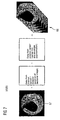
- FIG. 7 an IVMRI sectional image, captured by an imaging IVMRI sensor, of the region of a vessel under investigation and a schematic representation of a three-dimensional solid dataset constructed from a number of IVMRI sectional images
- FIG. 8 an IVUS sectional image and a solid dataset derived from it
- FIG. 9 an OCT sectional image and a solid dataset derived from it
- FIG. 10 a combined IVUS/OCT sectional image and a solid dataset derived from it
- FIG. 11 a schematic sketch illustrating the time-displaced, pulsed communication of detector signals.
- the cryocatheter 2 shown in FIG. 1 has an outer catheter sheath 4 and a rounded catheter tip 8 arranged at its distal end 6 .
- a balloon 10 which can be expanded by an expansion and cooling agent K, is provided near to the catheter tip 8 , with a stent 12 arranged on its outside.
- Liquid nitrogen is kept available in an external storage container as the expansion and cooling agent K, and if required is pumped at a pressure of 8-15 bar into the balloon, through a feed line 15 which runs through the catheter inner 14 of the catheter.
- the vessel wall in the region of the balloon 10 is greatly cooled by the nitrogen which evaporates while still within the feed line 15 or when it enters the balloon 10 .
- temperatures of between ⁇ 10° C. and ⁇ 80° C. in the interior of the balloon are advantageous.
- a recurrence of the vessel stenosis (restenosis) is thereby prevented.
- the stent 12 which is in the form of a metallic wire mesh, is stretched beyond its elastic limits so that subsequently to the balloon stretching it retains its shape.
- the stent 12 which was originally fixed to the balloon 10 , then separates from the balloon 10 and remains in the widened coronary vessel as a support to the vessel even after removal of the cryocatheter 2 . Before drawing the cryocatheter 2 out from the vessel, the expansion and cooling agent K in the balloon 10 is completely drained.
- an outlet duct (not shown here) is provided, running in the catheter inner 14 .
- an inner balloon nested within an outer balloon can also be provided.
- the stent 12 is optional; depending on the circumstances of the individual case the implantation of a stent may be forgone.
- the cryocatheter 2 is equipped with an image capture device which incorporates an imaging sensor 16 for intravascular imaging.
- the imaging sensor 16 is a so-called IVMRI sensor for intravascular magnetic resonance tomography.
- a permanent magnet or an electromagnet is integrated into the IVMRI sensor for the purpose of generating a static magnetic field, and a coil which works as both a transmission and receiving coil.
- the magnet creates field gradients of, preferably, 2 T/m up to 150 T/m in the neighborhood of the vessel or organ which is to be investigated.
- “in the neighborhood” means at a distance of up to 20 mm from the magnet.
- Through the coil depending on the strength of the magnetic field, it is possible to tap off radio waves in the frequency range from 2 MHz up to 250 MHz for the purpose of exciting the surrounding body tissue. Higher static magnetic field strengths call for higher frequencies in the excitation field.
- the coil also serves to receive the associated “response” of the bodily tissue. Alternatively, separate transmission and receiving coils can be provided.
- the IVMRI sensor and the electronic circuits provided for the purpose of signal processing and analysis are laid out in such a way that they work even if the magnetic field is comparatively inhomogeneous with high local field gradients, and can generate appropriate magnetic resonance images.
- the echo signals which are received are affected in a characteristic way by the microscopic diffusion of water molecules in the tissue under investigation, thus generally permitting an excellent representation and differentiation between different soft parts, e.g. between lipid layers and fibrous tissue.
- the static magnetic field can also be produced by external magnets.
- the dynamic fields i.e. the radio waves
- the dynamic fields are however produced intravascularly, i.e. by transmission and receiving units arranged on the cryocatheter 2 .
- the imaging sensor 16 is a so-called IVUS sensor for intravascular ultrasonic imaging.
- the IVUS sensor has appropriate ultrasonic transducers for the emission of primary ultrasonic waves and the reception of reflected ones, such as in the form of piezo-electric elements.
- Intravascular ultrasonic imaging is particularly suitable for the mapping of deeper-lying tissue layers and vessel structures.
- the imaging sensor 16 can be a so-called OCT sensor for optical coherence tomography.
- OCT sensor for optical coherence tomography.
- surface structures on the vessel wall can be shown in particular detail, at high resolution.
- the imaging sensor 16 which is generally directionally sensitive and directed radially outwards, can be rotated via a flexible drive shaft 18 which runs through the catheter inner 14 , so that a cross-sectional image of the section of the vessel under investigation covering 360° can be sampled.
- a rotational drive 22 is provided at the free end 20 of the cryocatheter 2 , closed off from the patients body.
- the catheter sheath 4 Around the imaging sensor 16 , the catheter sheath 4 has a window 24 which is transparent for the imaging method.
- the materials of the balloon 10 and the stent 12 are chosen, in the case of IVMRI or IVUS imaging, such that they produce no noticeable weakening or screening of the MRI radio signals or the ultrasonic waves.
- the OCT sensor is arranged relative to the balloon 10 in such a way that the light waves can be tapped off and injected without distortion.
- the signals supplied by the imaging sensor 16 are conducted via a signal line 26 , which also runs in the catheter inner 14 , to a connection adapter 28 , at the end 20 of the catheter 2 which is closed off from the patient's body, and from there via a signal interface 30 which is shown schematically to an analysis and control unit which is described below.
- the voltage supply for the imaging sensor 16 can be effected via supply lines, not shown in detail here, which run in parallel with the signal line(s) 26 .
- the signal and supply lines 26 can also be integrated into the drive shaft 18 .
- the signal line 26 which runs in the catheter inner 14 can take the form of a light guide (glass fiber).
- the light guide can also be integrated into the drive shaft 18 .
- the electrical signal and supply lines 26 have in addition a nanocoating to screen them from external magnetic fields and for protection against electromagnetic interference.
- the catheter tip 8 Furthermore, in the region of the catheter tip 8 are attached several electromagnetic position sensors 32 . For each direction in a three-dimensional coordinate system one transmission coil is provided, this communicating a corresponding position signal to a detector or signal receiver which is assigned to it and is arranged outside the catheter and outside the body of the patient under investigation. Using the position signals, recorded by the detectors and processed in the downstream analysis and control unit, it is possible to determine the current position and alignment of the catheter tip 8 in space.
- a contrast agent feed line Arranged in the catheter inner 14 are two contrast agent feed lines, not shown in FIG. 1 , each of which opens out at an outlet close to the catheter tip 8 or the imaging sensor 16 : one of these feed lines is used, depending on the sensor type, to feed an MRI contrast agent or an ultrasound contrast agent into the region of the investigation and treatment, while an X-ray contrast agent can be injected via the other feed line, for coronary angiography.
- the final item which is also provided on the catheter tip 8 is a magnetic element, in the form of an electromagnet, which can be actuated via an external analysis and control unit, which if necessary interacts with a magnetic guidance field which can be applied externally, thereby allowing the catheter tip 8 to be navigated and guided magnetically.
- the position sensors 32 arranged in the catheter tip 8 , also to be used as electromagnets for magnetic guidance.
- the position sensors 32 exercise a dual function, whereby it is possible to switch between the one function and the other by means of the analysis and control unit.
- the cryocatheter shown in FIG. 2 has similar functional units to the catheter described for FIG. 1 .
- the electrical functional units including in particular the imaging sensor 16 and the position sensors 32 , have been consistently separated from the other functional units, which have a mainly mechanical function.
- the cryocatheter 2 is thus made up of two main components: first, an outer body 34 or outer catheter which incorporates the outer catheter sheath 4 , the balloon 10 , the stent 12 plus the expansion agent feed line 15 and the contrast agent feed lines, and secondly an inner body 38 or inner catheter which can be pushed into a corresponding cavity 36 in the outer body 34 .
- the inner body 38 On or in the inner body 38 are arranged not only the imaging sensor 16 and the electromagnetic position sensors 32 but also the associated signal and supply lines 26 together with the drive shaft 18 for the imaging sensor 16 .
- the two main components of the cryocatheter 2 , the inner body 38 and the outer body 34 can easily be taken apart, as shown in FIG. 2 .
- the inner body 38 is simply pushed into the cavity 36 in the outer body 34 , as indicated in FIG. 2 by the two directional arrows 40 . This can be effected before or even after the introduction of the outer catheter 34 into a coronary vessel which is under investigation in a person. It is therefore even possible to put together a combination of several different inner and outer catheters, which are different but commensurable, which is particularly suitable for the purpose for which it is being used.
- FIG. 3 shows a further preferred form of embodiment of the cryocatheter 2 , in which two different imaging sensors 16 ′ and 16 ′′, which can be rotated by a common drive shaft 18 , are arranged in the region of the catheter tip 8 .
- the sensors 16 ′ and 16 ′′ which are arranged one behind the other in a lengthwise direction, could be for example an IVUS sensor and an OCT sensor, where the IVUS sensor could equally well be the front or the rear sensor when looking out from the catheter tip 8 .
- a further preferred combination is made up of an IVUS sensor and an IVMRI sensor. In these cases too, a construction with an inner catheter and a separate outer catheter is possible, see FIG. 4 .
- FIG. 5 shows in schematic form some components of medical investigation and treatment equipment 42 which incorporates the cryocatheter 2 .
- the cryocatheter 2 has already been introduced into a body vessel 44 to be investigated.
- the imaging sensor 16 at the distal end 6 of the cryocatheter 2 is linked on the signal side to an analysis and control unit 46 via a connection adapter 28 arranged at the end 20 which is closed off from the body.
- the analysis and control unit 46 is also connected, on the signal side, to one or more position signal receivers 48 arranged in the space around the patient, which receive position signals emitted by the position transmitters 32 arranged on the catheter. This permits the position of the catheter tip 8 within a fixed three-dimensional system of coordinates, to be calculated in the analysis and control unit 46 .
- cross-sectional images of the vessel under investigation 44 are generated, and postprocessed if appropriate, from the sensor signals of the imaging sensor 16 , in doing which it is also possible to construct reduced-artifact three-dimensional volume datasets by incorporating the position data communicated by the position sensors 32 .
- the images thus generated and the data for the region of the vessel under investigation can be displayed on a display monitor of a display unit 52 , and thus support the responsible doctor in the diagnosis and treatment of vessel diseases and in manipulating the cryocatheter 2 .
- the connection adapter 28 is used to effect not only the electrical link from the signaling elements to the analysis and control unit 46 but also the mechanical linkage of the cryocatheter 2 to further external operating devices.
- These include, in particular, a pump for the expansion agent, which pumps the expansion and cooling agent K, which is stored and cooled in a storage container 54 , into the balloon 10 of the cryocatheter 2 , and at least one contrast agent injector 56 , where the expansion agent pump and the contrast agent injector 56 can each be controlled or regulated, as applicable, through the central control unit 46 .
- the associated (infrared) light source is generally also arranged outside the cryocatheter 2 , with its connection to the light guide which runs in the catheter inner 14 being effected via the connection adapter 28 .
- X-ray equipment 59 shown here by dashed lines, in particular cardiological X-ray equipment, which is actuated and read out through the shared analysis and control unit 46 .
- the external X-ray image data and the intravascular image data can be exchanged and, for example, combined by image merging.
- the merged images, which are particularly informative, can then be displayed on the display monitor of the shared display unit 52 .
- the user interface for operating the complete system is designed for the common operation of the X-ray system 59 and the cryocatheter 2 .
- the cryocatheter 2 is now introduced into the vessel 44 under X-ray control. This may be effected with the addition of an X-ray contrast agent. To give improved visibility under X-ray illumination, one or more X-ray opaque markers are provided, above all in the region of the catheter tip 8 . Even while it is being introduced, the image capture device integrated into the cryocatheter 2 can be active, and can supply images of the vessel 44 . Under some circumstances, it is therefore possible to forgo the X-ray control. When the desired target location has been reached, the stenosis or vessel wall, as applicable, can be observed at a higher resolution with the help of the image capture device.
- this enables information to be obtained about the stenosis, and on the other hand the placing of the balloon 10 , and any stent 12 , can be checked. If it is found that the positioning is not correct, the cryocatheter 2 can simply be pushed a little further or pulled back until the balloon 10 or stent 12 , as applicable, is correctly positioned. This is all possible because the imaging sensor 16 is designed, and is arranged at the distal end 6 of the cryocatheter 2 , for recording the region of the vessel immediately alongside the balloon 10 or stent 12 , as applicable.
- the balloon 10 When the balloon 10 or the stent 12 , as applicable, has been correctly positioned, the balloon 10 is then expanded, by means of the expansion and cooling agent K conveyed by the expansion agent pump.
- the balloon 10 undergoes a defined stretching, the stent 12 , which is generally a plastically deformable metal mesh, is uniformly stretched. In doing this, the balloon 10 is blown up far enough for the stent 12 to be roughly fixed to the inner wall of the vessel.
- cryotherapy of the vessel wall surrounding the balloon 10 is effected.
- the balloon 10 is somewhat deflated again, to enable the position and orientation of the stent 12 to be checked via the image capture device 16 .
- the balloon 10 is reinflated at a higher pressure, and the stent 12 finally fixed in the vessel 44 .
- a final check can be carried out via the image capture device 16 , after which the cryocatheter 2 is pulled out of the vessel 44 .
- the control and analysis unit 46 includes, apart from a preprocessor 62 in which the sensor signals are appropriately amplified, filtered, digitized and prepared for further digital editing, which is connected to the imaging sensor 16 on the catheter side via a signal line 61 , an image processing module 64 , in which the actual visualization and posttreatment of the sensor data is effected with the help of facilities implemented by familiar hardware or software facilities.
- the image processing module 64 incorporates a 3D correction module 66 , with a so-called movement and gating processor which, by referring back to the position data for the catheter tip 8 provided by the position signal receiver 48 , reconstructs the center line and the envelope of the vessel for the section of the vessel reproduced in the sectional images, and then combines a number of individual images 67 , 67 ′, 67 ′′ into a reduced-artifact three-dimensional volume dataset 68 , 68 ′, 68 ′′.
- This is shown schematically in FIG. 7 to FIG. 9 , and indeed separately for IVMRI images ( FIG. 7 ), IVUS images ( FIG. 8 ) and for OCT images ( FIG. 9 ).
- the envelope of the vessel and any further applicable geometric parameters of the vessel 44 it is also possible to combine the images, reconstructed three-dimensionally, on a surface basis with other anatomical image data (e.g. 3D angiography, ultrasound) for the same section of the vessel, and then to show this in merged form.
- anatomical image data e.g. 3D angiography, ultrasound
- an image merging unit integrated into the image processing unit 64 serves to generate a common image from the separate images produced respectively using the signals from the OCT sensor or from the IVUS sensor.
- image merging is merely an overlaying of the individual OCT and IVUS images.
- the IVUS image has a very good resolution for deeper-lying tissue layers.
- the OCT image has a very high resolution in the nearby region, making even microscopic images possible.
- the two partial images are constructed to be complementary, so that the OCT section fits exactly into the space in the IVUS image.
- the OCT section of the image and the IVUS section of the image can be blended into each other by means of appropriate image processing programs in such a way that no separating line or contour can be discerned.
- An example of an IVUS/OCT image 80 which has been blended in this way is shown in FIG. 11 . From the two-dimensional images 80 it is again possible to generate three-dimensional reduced-artifact volume datasets 81 .
- the above embodiments can also be applied with appropriate interpretation to other combinations of imaging sensors, e.g. IVUS/IVMRI.
- the intravascular images from the imaging sensor 16 can be overlaid or blended in the image merging unit with the X-ray images from the angiographic X-ray unit 59 , or even with earlier records which are already available from other image generation methods (for example CT, MRI, PET or SPECT), which will preferably be provided or communicated, as appropriate, through a DICOM interface.
- image generation methods for example CT, MRI, PET or SPECT
- the 3D correction module 66 shown in FIG. 6 is furthermore linked to a signal interface 69 , which has a data link to one or more movement sensors 70 for measuring the breathing movements of the patient 74 held on an examination chair or examination table 72 , and to various physiological sensors such as for ECG, pulse, respiration or blood pressure. It is thus also possible to take into account these items of data in the artifact correction of the 3D image.
- Some of the physiological sensors and the movement sensors 70 take the form of active or passive RFID transponders, and can be read out wirelessly by an RFID reader 76 integrated into the signal interface 69 or connected to it.
- the RFID transponder concerned will, for example, incorporate an RFID microchip integrated into a plaster, the plaster being stuck onto the skin of the patient during the investigation.
- the data captured by the movement sensors 70 and the physiological sensors can be displayed on the display monitor of the display unit 52 together with the image data and additional technical data, for example about the phase position or speed of rotation of the imaging sensor 16 , or the distance so far moved by the cryocatheter 2 .
- Connected to the display unit 52 or to the analysis and control unit 46 is an input/output unit, I/O unit for short, through which the user can make inputs. In particular, he can influence the display of the image(s) shown on the display monitor.
- the I/O unit can take the form of a keyboard or an operating console.
- the MR signal which is used for imaging Finally, the rectangular-shaped signal windows in the bottom graph represent the time intervals which are favorable for the reading out of the position sensors 32 .
- a readout of the detector signals which has a time offset of this type is appropriate particularly for IVMRI imaging, but it can also be put to use in a similar form with IVUS or OCT imaging.
Landscapes
- Health & Medical Sciences (AREA)
- Life Sciences & Earth Sciences (AREA)
- Surgery (AREA)
- Engineering & Computer Science (AREA)
- Heart & Thoracic Surgery (AREA)
- Veterinary Medicine (AREA)
- Public Health (AREA)
- Biomedical Technology (AREA)
- Animal Behavior & Ethology (AREA)
- General Health & Medical Sciences (AREA)
- Medical Informatics (AREA)
- Molecular Biology (AREA)
- Biophysics (AREA)
- Nuclear Medicine, Radiotherapy & Molecular Imaging (AREA)
- Physics & Mathematics (AREA)
- Pathology (AREA)
- Radiology & Medical Imaging (AREA)
- Anesthesiology (AREA)
- Child & Adolescent Psychology (AREA)
- Pulmonology (AREA)
- Computer Vision & Pattern Recognition (AREA)
- Hematology (AREA)
- Otolaryngology (AREA)
- Electromagnetism (AREA)
- Oral & Maxillofacial Surgery (AREA)
- Ultra Sonic Daignosis Equipment (AREA)
- Endoscopes (AREA)
- Magnetic Resonance Imaging Apparatus (AREA)
Applications Claiming Priority (3)
| Application Number | Priority Date | Filing Date | Title |
|---|---|---|---|
| DE102005050344A DE102005050344A1 (de) | 2005-10-20 | 2005-10-20 | Kryokatheter zur Einführung in ein Körpergefäß sowie medizinische Untersuchungs- und Behandlungsvorrichtung |
| DE102005050344.6 | 2005-10-20 | ||
| DE102005050344 | 2005-10-20 |
Publications (2)
| Publication Number | Publication Date |
|---|---|
| US20070093710A1 US20070093710A1 (en) | 2007-04-26 |
| US9237919B2 true US9237919B2 (en) | 2016-01-19 |
Family
ID=37912563
Family Applications (1)
| Application Number | Title | Priority Date | Filing Date |
|---|---|---|---|
| US11/583,447 Expired - Fee Related US9237919B2 (en) | 2005-10-20 | 2006-10-19 | Cryocatheter for introduction into a body vessel together with medical investigation and treatment equipment |
Country Status (2)
| Country | Link |
|---|---|
| US (1) | US9237919B2 (de) |
| DE (1) | DE102005050344A1 (de) |
Cited By (1)
| Publication number | Priority date | Publication date | Assignee | Title |
|---|---|---|---|---|
| US11633224B2 (en) | 2020-02-10 | 2023-04-25 | Icecure Medical Ltd. | Cryogen pump |
Families Citing this family (195)
| Publication number | Priority date | Publication date | Assignee | Title |
|---|---|---|---|---|
| US7455666B2 (en) | 2001-07-13 | 2008-11-25 | Board Of Regents, The University Of Texas System | Methods and apparatuses for navigating the subarachnoid space |
| US7756583B2 (en) | 2002-04-08 | 2010-07-13 | Ardian, Inc. | Methods and apparatus for intravascularly-induced neuromodulation |
| US8347891B2 (en) | 2002-04-08 | 2013-01-08 | Medtronic Ardian Luxembourg S.A.R.L. | Methods and apparatus for performing a non-continuous circumferential treatment of a body lumen |
| WO2005041748A2 (en) | 2003-09-12 | 2005-05-12 | Minnow Medical, Llc | Selectable eccentric remodeling and/or ablation of atherosclerotic material |
| US8396548B2 (en) | 2008-11-14 | 2013-03-12 | Vessix Vascular, Inc. | Selective drug delivery in a lumen |
| US9713730B2 (en) | 2004-09-10 | 2017-07-25 | Boston Scientific Scimed, Inc. | Apparatus and method for treatment of in-stent restenosis |
| US8784336B2 (en) | 2005-08-24 | 2014-07-22 | C. R. Bard, Inc. | Stylet apparatuses and methods of manufacture |
| US8019435B2 (en) | 2006-05-02 | 2011-09-13 | Boston Scientific Scimed, Inc. | Control of arterial smooth muscle tone |
| US20080140061A1 (en) * | 2006-09-08 | 2008-06-12 | Arbel Medical Ltd. | Method And Device For Combined Treatment |
| AU2007310986B2 (en) | 2006-10-18 | 2013-07-04 | Boston Scientific Scimed, Inc. | Inducing desirable temperature effects on body tissue |
| CA2666663C (en) | 2006-10-18 | 2016-02-09 | Minnow Medical, Inc. | System for inducing desirable temperature effects on body tissue |
| JP5312337B2 (ja) | 2006-10-18 | 2013-10-09 | べシックス・バスキュラー・インコーポレイテッド | 標的組織の選択的な処置のための調節されたrfエネルギーおよび電気的な組織の特徴付け |
| US7794407B2 (en) | 2006-10-23 | 2010-09-14 | Bard Access Systems, Inc. | Method of locating the tip of a central venous catheter |
| US8388546B2 (en) | 2006-10-23 | 2013-03-05 | Bard Access Systems, Inc. | Method of locating the tip of a central venous catheter |
| WO2008063573A2 (en) * | 2006-11-17 | 2008-05-29 | Varian Medical Systems Technologies, Inc. | Dynamic patient positioning system |
| CA2687876A1 (en) * | 2007-05-23 | 2009-03-05 | Oscillon Ltd. | Apparatus and method for guided chronic total occlusion penetration |
| US20100162730A1 (en) * | 2007-06-14 | 2010-07-01 | Arbel Medical Ltd. | Siphon for delivery of liquid cryogen from dewar flask |
| US8003157B2 (en) | 2007-06-15 | 2011-08-23 | Abbott Cardiovascular Systems Inc. | System and method for coating a stent |
| US8677650B2 (en) * | 2007-06-15 | 2014-03-25 | Abbott Cardiovascular Systems Inc. | Methods and devices for drying coated stents |
| US20100324546A1 (en) * | 2007-07-09 | 2010-12-23 | Alexander Levin | Cryosheath |
| WO2009009802A1 (en) * | 2007-07-12 | 2009-01-15 | Volcano Corporation | Oct-ivus catheter for concurrent luminal imaging |
| DE102007043732A1 (de) * | 2007-09-13 | 2009-04-02 | Siemens Ag | Herzmuskelgewebe-Ablationsvorrichtung zur Behandlung von Herzrhythmusstörungen durch Ablation von Herzmuskelgewebe bei einem Patienten sowie zugehöriger Katheter und zugehöriges Verfahren |
| DE102007043731A1 (de) * | 2007-09-13 | 2009-04-02 | Siemens Ag | Medizinische Bildaufnahmeeinrichtung, insbesondere zur Erstellung von Bildaufnahmen im Rahmen einer Behandlung von Herzrhythmusstörungen, sowie zugehöriges Verfahren |
| WO2009066292A1 (en) * | 2007-11-21 | 2009-05-28 | Arbel Medical Ltd. | Pumping unit for delivery of liquid medium from a vessel |
| US8849382B2 (en) | 2007-11-26 | 2014-09-30 | C. R. Bard, Inc. | Apparatus and display methods relating to intravascular placement of a catheter |
| US9456766B2 (en) | 2007-11-26 | 2016-10-04 | C. R. Bard, Inc. | Apparatus for use with needle insertion guidance system |
| US8781555B2 (en) | 2007-11-26 | 2014-07-15 | C. R. Bard, Inc. | System for placement of a catheter including a signal-generating stylet |
| US10524691B2 (en) | 2007-11-26 | 2020-01-07 | C. R. Bard, Inc. | Needle assembly including an aligned magnetic element |
| US9649048B2 (en) | 2007-11-26 | 2017-05-16 | C. R. Bard, Inc. | Systems and methods for breaching a sterile field for intravascular placement of a catheter |
| US10751509B2 (en) | 2007-11-26 | 2020-08-25 | C. R. Bard, Inc. | Iconic representations for guidance of an indwelling medical device |
| JP5452500B2 (ja) | 2007-11-26 | 2014-03-26 | シー・アール・バード・インコーポレーテッド | カテーテルの血管内留置のための統合システム |
| US9521961B2 (en) | 2007-11-26 | 2016-12-20 | C. R. Bard, Inc. | Systems and methods for guiding a medical instrument |
| US10449330B2 (en) | 2007-11-26 | 2019-10-22 | C. R. Bard, Inc. | Magnetic element-equipped needle assemblies |
| US20110015624A1 (en) * | 2008-01-15 | 2011-01-20 | Icecure Medical Ltd. | Cryosurgical instrument insulating system |
| US8478382B2 (en) | 2008-02-11 | 2013-07-02 | C. R. Bard, Inc. | Systems and methods for positioning a catheter |
| DE102008008667A1 (de) * | 2008-02-12 | 2009-08-13 | Siemens Aktiengesellschaft | Vorrichtung zur Anbringung an einem medizinischen Objekt und Verwendung der Vorrichtung |
| DE102008013858A1 (de) * | 2008-03-12 | 2009-09-24 | Siemens Aktiengesellschaft | Kathetervorrichtung und zugehörige medizinische Untersuchungs- und Behandlungseinrichtung |
| DE102008013856A1 (de) * | 2008-03-12 | 2009-09-24 | Siemens Aktiengesellschaft | Valvuloplastik-Katheter und zugehörige medizinische Untersuchungs- und Behandlungseinrichtung |
| DE102008013859A1 (de) * | 2008-03-12 | 2009-09-24 | Siemens Aktiengesellschaft | Katheter mit einer Vorrichtung zur septalen Punktion und zugehörige medizinische Untersuchungs- und Behandlungseinrichtung |
| DE102008013860A1 (de) * | 2008-03-12 | 2009-09-24 | Siemens Aktiengesellschaft | Kathetervorrichtung und zugehörige medizinische Untersuchungs- und Behandlungseinrichtung |
| EP2303168A1 (de) | 2008-04-16 | 2011-04-06 | Arbel Medical Ltd. | Kryochirurgisches instrument mit verbessertem wärmeaustausch |
| US20090264866A1 (en) * | 2008-04-18 | 2009-10-22 | Boston Scientific Scimed, Inc. | Catheter Identification Inserts |
| DE102008019827A1 (de) * | 2008-04-19 | 2009-10-29 | Biotronik Crm Patent Ag | Steuerbare Elektrode zur tiefen Hirnstimulation |
| US9901714B2 (en) | 2008-08-22 | 2018-02-27 | C. R. Bard, Inc. | Catheter assembly including ECG sensor and magnetic assemblies |
| US8437833B2 (en) | 2008-10-07 | 2013-05-07 | Bard Access Systems, Inc. | Percutaneous magnetic gastrostomy |
| US20100281917A1 (en) * | 2008-11-05 | 2010-11-11 | Alexander Levin | Apparatus and Method for Condensing Contaminants for a Cryogenic System |
| CN102271603A (zh) | 2008-11-17 | 2011-12-07 | 明诺医学股份有限公司 | 得知或未得知组织形态的选择性能量积累 |
| US7967814B2 (en) | 2009-02-05 | 2011-06-28 | Icecure Medical Ltd. | Cryoprobe with vibrating mechanism |
| US8162812B2 (en) | 2009-03-12 | 2012-04-24 | Icecure Medical Ltd. | Combined cryotherapy and brachytherapy device and method |
| US20100241058A1 (en) * | 2009-03-19 | 2010-09-23 | Ahmed Syed Yosuf | Oct guided tissue ablation |
| DE102009017370B3 (de) * | 2009-04-14 | 2010-12-09 | Erbe Elektromedizin Gmbh | Adapter zur Überdrucksicherung, Kryosonde mit entsprechendem Adapter und kryochirurgisches Gerät mit Überdrucksicherung |
| DE102009031402A1 (de) * | 2009-04-30 | 2010-11-11 | Erbe Elektromedizin Gmbh | Versorgungseinrichtung und Verfahren zur Dokumentation einer Operation |
| US20100305439A1 (en) * | 2009-05-27 | 2010-12-02 | Eyal Shai | Device and Method for Three-Dimensional Guidance and Three-Dimensional Monitoring of Cryoablation |
| JP5795576B2 (ja) | 2009-06-12 | 2015-10-14 | バード・アクセス・システムズ,インコーポレーテッド | 心電図(ecg)信号を使用して心臓内またはその近くに血管内デバイスを位置決めするコンピュータベースの医療機器の作動方法 |
| US9532724B2 (en) | 2009-06-12 | 2017-01-03 | Bard Access Systems, Inc. | Apparatus and method for catheter navigation using endovascular energy mapping |
| US20120093378A1 (en) * | 2009-07-06 | 2012-04-19 | Koninklijke Philips Electronics N.V. | Visualization of physiological parameters |
| WO2011019760A2 (en) | 2009-08-10 | 2011-02-17 | Romedex International Srl | Devices and methods for endovascular electrography |
| EP2517622A3 (de) | 2009-09-29 | 2013-04-24 | C. R. Bard, Inc. | Stillete zur Verwendung mit Vorrichtungen zur intravaskulären Positionierung eines Katheters |
| WO2011044387A2 (en) | 2009-10-07 | 2011-04-14 | The Board Of Regents Of The University Of Texas System | Pressure-sensing medical devices, systems and methods, and methods of forming medical devices |
| WO2011044421A1 (en) | 2009-10-08 | 2011-04-14 | C. R. Bard, Inc. | Spacers for use with an ultrasound probe |
| BR112012019354B1 (pt) | 2010-02-02 | 2021-09-08 | C.R.Bard, Inc | Método para localização de um dispositivo médico implantável |
| US7967815B1 (en) | 2010-03-25 | 2011-06-28 | Icecure Medical Ltd. | Cryosurgical instrument with enhanced heat transfer |
| EP2555699B1 (de) | 2010-04-09 | 2019-04-03 | Vessix Vascular, Inc. | Stromerzeugungs- und steuervorrichtung zur gewebebehandlung |
| US9192790B2 (en) | 2010-04-14 | 2015-11-24 | Boston Scientific Scimed, Inc. | Focused ultrasonic renal denervation |
| US7938822B1 (en) | 2010-05-12 | 2011-05-10 | Icecure Medical Ltd. | Heating and cooling of cryosurgical instrument using a single cryogen |
| CA2800813C (en) | 2010-05-28 | 2019-10-29 | C.R. Bard, Inc. | Apparatus for use with needle insertion guidance system |
| US8080005B1 (en) | 2010-06-10 | 2011-12-20 | Icecure Medical Ltd. | Closed loop cryosurgical pressure and flow regulated system |
| US8473067B2 (en) | 2010-06-11 | 2013-06-25 | Boston Scientific Scimed, Inc. | Renal denervation and stimulation employing wireless vascular energy transfer arrangement |
| US10390889B2 (en) * | 2010-07-26 | 2019-08-27 | St Jude Medical International Holding S.Á R.L. | Removable navigation system and method for a medical device |
| US9463062B2 (en) | 2010-07-30 | 2016-10-11 | Boston Scientific Scimed, Inc. | Cooled conductive balloon RF catheter for renal nerve ablation |
| US9358365B2 (en) | 2010-07-30 | 2016-06-07 | Boston Scientific Scimed, Inc. | Precision electrode movement control for renal nerve ablation |
| US9084609B2 (en) | 2010-07-30 | 2015-07-21 | Boston Scientific Scime, Inc. | Spiral balloon catheter for renal nerve ablation |
| US9155589B2 (en) | 2010-07-30 | 2015-10-13 | Boston Scientific Scimed, Inc. | Sequential activation RF electrode set for renal nerve ablation |
| US9408661B2 (en) | 2010-07-30 | 2016-08-09 | Patrick A. Haverkost | RF electrodes on multiple flexible wires for renal nerve ablation |
| WO2012019156A1 (en) | 2010-08-05 | 2012-02-09 | Medtronic Ardian Luxembourg S.A.R.L. | Cryoablation apparatuses, systems, and methods for renal neuromodulation |
| AU2011289513B2 (en) | 2010-08-09 | 2014-05-29 | C.R. Bard, Inc. | Support and cover structures for an ultrasound probe head |
| WO2012024577A2 (en) * | 2010-08-20 | 2012-02-23 | C.R. Bard, Inc. | Reconfirmation of ecg-assisted catheter tip placement |
| US8974451B2 (en) | 2010-10-25 | 2015-03-10 | Boston Scientific Scimed, Inc. | Renal nerve ablation using conductive fluid jet and RF energy |
| US20120130458A1 (en) | 2010-10-26 | 2012-05-24 | Medtronic Ardian Luxembourg S.A.R.L. | Neuromodulation cryotherapeutic devices and associated systems and methods |
| US9220558B2 (en) | 2010-10-27 | 2015-12-29 | Boston Scientific Scimed, Inc. | RF renal denervation catheter with multiple independent electrodes |
| WO2012058461A1 (en) | 2010-10-29 | 2012-05-03 | C.R.Bard, Inc. | Bioimpedance-assisted placement of a medical device |
| US9028485B2 (en) | 2010-11-15 | 2015-05-12 | Boston Scientific Scimed, Inc. | Self-expanding cooling electrode for renal nerve ablation |
| US9668811B2 (en) | 2010-11-16 | 2017-06-06 | Boston Scientific Scimed, Inc. | Minimally invasive access for renal nerve ablation |
| US9089350B2 (en) | 2010-11-16 | 2015-07-28 | Boston Scientific Scimed, Inc. | Renal denervation catheter with RF electrode and integral contrast dye injection arrangement |
| US9326751B2 (en) | 2010-11-17 | 2016-05-03 | Boston Scientific Scimed, Inc. | Catheter guidance of external energy for renal denervation |
| US9060761B2 (en) | 2010-11-18 | 2015-06-23 | Boston Scientific Scime, Inc. | Catheter-focused magnetic field induced renal nerve ablation |
| US9023034B2 (en) | 2010-11-22 | 2015-05-05 | Boston Scientific Scimed, Inc. | Renal ablation electrode with force-activatable conduction apparatus |
| US9192435B2 (en) | 2010-11-22 | 2015-11-24 | Boston Scientific Scimed, Inc. | Renal denervation catheter with cooled RF electrode |
| US20120157993A1 (en) | 2010-12-15 | 2012-06-21 | Jenson Mark L | Bipolar Off-Wall Electrode Device for Renal Nerve Ablation |
| CN105796177B (zh) * | 2010-12-23 | 2018-05-29 | 巴德阿克塞斯系统股份有限公司 | 用于引导医疗器械的系统和方法 |
| WO2012100095A1 (en) | 2011-01-19 | 2012-07-26 | Boston Scientific Scimed, Inc. | Guide-compatible large-electrode catheter for renal nerve ablation with reduced arterial injury |
| US20120245575A1 (en) * | 2011-03-23 | 2012-09-27 | Halt Medical Inc. | User interface and navigational tool for remote control of an anchored rf ablation device for destruction of tissue masses |
| RU2462208C1 (ru) * | 2011-04-07 | 2012-09-27 | Николай Васильевич Мерзликин | Эндоскопический криоаппликатор |
| CN103517731B (zh) | 2011-04-08 | 2016-08-31 | 柯惠有限合伙公司 | 用于去除肾交感神经和离子电渗式药物传递的离子电渗式药物传递系统和方法 |
| KR101832021B1 (ko) | 2011-04-13 | 2018-02-23 | 크요테라피유틱스 게엠베하 | 극저온 에너지를 사용하는 플라크 안정화 |
| CN103930061B (zh) | 2011-04-25 | 2016-09-14 | 美敦力阿迪安卢森堡有限责任公司 | 用于限制导管壁低温消融的有关低温球囊限制部署的装置及方法 |
| US10722282B2 (en) | 2011-06-14 | 2020-07-28 | Aerin Medical, Inc. | Methods and devices to treat nasal airways |
| US9415194B2 (en) | 2011-06-14 | 2016-08-16 | Aerin Medical Inc. | Post nasal drip treatment |
| US9237924B2 (en) | 2011-06-14 | 2016-01-19 | Aerin Medical, Inc. | Methods and devices to treat nasal airways |
| US10456185B2 (en) | 2011-06-14 | 2019-10-29 | Aerin Medical, Inc. | Methods and devices to treat nasal airways |
| US11304746B2 (en) | 2011-06-14 | 2022-04-19 | Aerin Medical Inc. | Method of treating airway tissue to reduce mucus secretion |
| US11033318B2 (en) | 2011-06-14 | 2021-06-15 | Aerin Medical, Inc. | Methods and devices to treat nasal airways |
| US11241271B2 (en) | 2011-06-14 | 2022-02-08 | Aerin Medical Inc. | Methods of treating nasal airways |
| CN105662402B (zh) | 2011-07-06 | 2019-06-18 | C·R·巴德股份有限公司 | 用于插入引导系统的针长度确定和校准 |
| AU2012283908B2 (en) | 2011-07-20 | 2017-02-16 | Boston Scientific Scimed, Inc. | Percutaneous devices and methods to visualize, target and ablate nerves |
| AU2012287189B2 (en) | 2011-07-22 | 2016-10-06 | Boston Scientific Scimed, Inc. | Nerve modulation system with a nerve modulation element positionable in a helical guide |
| US9387031B2 (en) | 2011-07-29 | 2016-07-12 | Medtronic Ablation Frontiers Llc | Mesh-overlayed ablation and mapping device |
| USD724745S1 (en) | 2011-08-09 | 2015-03-17 | C. R. Bard, Inc. | Cap for an ultrasound probe |
| USD699359S1 (en) | 2011-08-09 | 2014-02-11 | C. R. Bard, Inc. | Ultrasound probe head |
| US9186210B2 (en) | 2011-10-10 | 2015-11-17 | Boston Scientific Scimed, Inc. | Medical devices including ablation electrodes |
| WO2013055815A1 (en) | 2011-10-11 | 2013-04-18 | Boston Scientific Scimed, Inc. | Off -wall electrode device for nerve modulation |
| US9420955B2 (en) | 2011-10-11 | 2016-08-23 | Boston Scientific Scimed, Inc. | Intravascular temperature monitoring system and method |
| US9364284B2 (en) | 2011-10-12 | 2016-06-14 | Boston Scientific Scimed, Inc. | Method of making an off-wall spacer cage |
| EP2768568B1 (de) | 2011-10-18 | 2020-05-06 | Boston Scientific Scimed, Inc. | Ballonkatheter mit integrierter vernetzung |
| EP2768563B1 (de) | 2011-10-18 | 2016-11-09 | Boston Scientific Scimed, Inc. | Biegbare medizinische vorrichtungen |
| US9211107B2 (en) | 2011-11-07 | 2015-12-15 | C. R. Bard, Inc. | Ruggedized ultrasound hydrogel insert |
| EP2775948B1 (de) | 2011-11-08 | 2018-04-04 | Boston Scientific Scimed, Inc. | Ostiale nierennervenablation |
| WO2013074813A1 (en) | 2011-11-15 | 2013-05-23 | Boston Scientific Scimed, Inc. | Device and methods for renal nerve modulation monitoring |
| US9119632B2 (en) | 2011-11-21 | 2015-09-01 | Boston Scientific Scimed, Inc. | Deflectable renal nerve ablation catheter |
| US9265969B2 (en) | 2011-12-21 | 2016-02-23 | Cardiac Pacemakers, Inc. | Methods for modulating cell function |
| AU2012358146B2 (en) | 2011-12-23 | 2015-09-17 | Boston Scientific Scimed, Inc. | Methods and apparatuses for remodeling tissue of or adjacent to a body passage |
| WO2013101452A1 (en) | 2011-12-28 | 2013-07-04 | Boston Scientific Scimed, Inc. | Device and methods for nerve modulation using a novel ablation catheter with polymeric ablative elements |
| US9050106B2 (en) | 2011-12-29 | 2015-06-09 | Boston Scientific Scimed, Inc. | Off-wall electrode device and methods for nerve modulation |
| FR2985899B1 (fr) * | 2012-01-24 | 2015-04-17 | Gen Electric | Traitement d'images de radiologie interventionnelles par analyse de l'ecg |
| EP2832287B1 (de) * | 2012-03-29 | 2017-04-26 | Terumo Kabushiki Kaisha | Bilddiagnosevorrichtung und sonde |
| US9241752B2 (en) | 2012-04-27 | 2016-01-26 | Medtronic Ardian Luxembourg S.A.R.L. | Shafts with pressure relief in cryotherapeutic catheters and associated devices, systems, and methods |
| WO2013162700A1 (en) | 2012-04-27 | 2013-10-31 | Medtronic Ardian Luxembourg Sarl | Cryotherapeutic devices for renal neuromodulation and associated systems and methods |
| US10660703B2 (en) | 2012-05-08 | 2020-05-26 | Boston Scientific Scimed, Inc. | Renal nerve modulation devices |
| CN104837413B (zh) | 2012-06-15 | 2018-09-11 | C·R·巴德股份有限公司 | 检测超声探测器上可移除帽的装置及方法 |
| DE102012213456A1 (de) * | 2012-07-31 | 2014-02-06 | Siemens Aktiengesellschaft | Katheter mit Ultraschallsensor und Verfahren zum Erzeugen einer Volumengrafik mittels des Katheters |
| CN104540465A (zh) | 2012-08-24 | 2015-04-22 | 波士顿科学西美德公司 | 带有含单独微孔隙区域的球囊的血管内导管 |
| US9113911B2 (en) | 2012-09-06 | 2015-08-25 | Medtronic Ablation Frontiers Llc | Ablation device and method for electroporating tissue cells |
| US9173696B2 (en) | 2012-09-17 | 2015-11-03 | Boston Scientific Scimed, Inc. | Self-positioning electrode system and method for renal nerve modulation |
| WO2014047411A1 (en) | 2012-09-21 | 2014-03-27 | Boston Scientific Scimed, Inc. | System for nerve modulation and innocuous thermal gradient nerve block |
| US10549127B2 (en) | 2012-09-21 | 2020-02-04 | Boston Scientific Scimed, Inc. | Self-cooling ultrasound ablation catheter |
| US9801756B2 (en) * | 2012-09-28 | 2017-10-31 | Zoll Circulation, Inc. | Intravascular heat exchange catheter and system with RFID coupling |
| CN104869930B (zh) | 2012-10-10 | 2020-12-25 | 波士顿科学国际有限公司 | 肾神经调制装置和方法 |
| WO2014143571A1 (en) | 2013-03-11 | 2014-09-18 | Boston Scientific Scimed, Inc. | Medical devices for modulating nerves |
| WO2014163987A1 (en) | 2013-03-11 | 2014-10-09 | Boston Scientific Scimed, Inc. | Medical devices for modulating nerves |
| US9808311B2 (en) | 2013-03-13 | 2017-11-07 | Boston Scientific Scimed, Inc. | Deflectable medical devices |
| WO2014149690A2 (en) | 2013-03-15 | 2014-09-25 | Boston Scientific Scimed, Inc. | Medical devices and methods for treatment of hypertension that utilize impedance compensation |
| US10265122B2 (en) | 2013-03-15 | 2019-04-23 | Boston Scientific Scimed, Inc. | Nerve ablation devices and related methods of use |
| CN105473090B (zh) | 2013-03-15 | 2019-05-03 | 波士顿科学国际有限公司 | 重建身体通道的组织或邻近身体通道的组织的方法及装置 |
| US10543037B2 (en) | 2013-03-15 | 2020-01-28 | Medtronic Ardian Luxembourg S.A.R.L. | Controlled neuromodulation systems and methods of use |
| US9943365B2 (en) | 2013-06-21 | 2018-04-17 | Boston Scientific Scimed, Inc. | Renal denervation balloon catheter with ride along electrode support |
| JP2016524949A (ja) | 2013-06-21 | 2016-08-22 | ボストン サイエンティフィック サイムド,インコーポレイテッドBoston Scientific Scimed,Inc. | 回転可能シャフトを有する腎神経アブレーション用医療装置 |
| US9707036B2 (en) | 2013-06-25 | 2017-07-18 | Boston Scientific Scimed, Inc. | Devices and methods for nerve modulation using localized indifferent electrodes |
| EP3016605B1 (de) | 2013-07-01 | 2019-06-05 | Boston Scientific Scimed, Inc. | Medizinische vorrichtungen zur nierennervenablation |
| CN105377170A (zh) | 2013-07-11 | 2016-03-02 | 波士顿科学国际有限公司 | 具有可伸展电极组件的医疗装置 |
| EP3019105B1 (de) | 2013-07-11 | 2017-09-13 | Boston Scientific Scimed, Inc. | Vorrichtungen zur nervenmodulation |
| WO2015010074A1 (en) | 2013-07-19 | 2015-01-22 | Boston Scientific Scimed, Inc. | Spiral bipolar electrode renal denervation balloon |
| EP3024406B1 (de) | 2013-07-22 | 2019-06-19 | Boston Scientific Scimed, Inc. | Medizinische geräte zur renalen nervenablation |
| US10695124B2 (en) | 2013-07-22 | 2020-06-30 | Boston Scientific Scimed, Inc. | Renal nerve ablation catheter having twist balloon |
| JP6159888B2 (ja) | 2013-08-22 | 2017-07-05 | ボストン サイエンティフィック サイムド,インコーポレイテッドBoston Scientific Scimed,Inc. | 腎神経変調バルーンへの接着性を向上させたフレキシブル回路 |
| US9895194B2 (en) | 2013-09-04 | 2018-02-20 | Boston Scientific Scimed, Inc. | Radio frequency (RF) balloon catheter having flushing and cooling capability |
| US10603059B2 (en) | 2013-09-13 | 2020-03-31 | Aerin Medical Inc. | Hyaline cartilage shaping |
| CN105530885B (zh) | 2013-09-13 | 2020-09-22 | 波士顿科学国际有限公司 | 具有气相沉积覆盖层的消融球囊 |
| WO2015057521A1 (en) | 2013-10-14 | 2015-04-23 | Boston Scientific Scimed, Inc. | High resolution cardiac mapping electrode array catheter |
| US11246654B2 (en) | 2013-10-14 | 2022-02-15 | Boston Scientific Scimed, Inc. | Flexible renal nerve ablation devices and related methods of use and manufacture |
| AU2014334574B2 (en) | 2013-10-15 | 2017-07-06 | Boston Scientific Scimed, Inc. | Medical device balloon |
| US9770606B2 (en) | 2013-10-15 | 2017-09-26 | Boston Scientific Scimed, Inc. | Ultrasound ablation catheter with cooling infusion and centering basket |
| WO2015057961A1 (en) | 2013-10-18 | 2015-04-23 | Boston Scientific Scimed, Inc. | Balloon catheters with flexible conducting wires and related methods of use and manufacture |
| JP2016534842A (ja) | 2013-10-25 | 2016-11-10 | ボストン サイエンティフィック サイムド,インコーポレイテッドBoston Scientific Scimed,Inc. | 除神経フレックス回路における埋め込み熱電対 |
| US10568686B2 (en) | 2013-11-21 | 2020-02-25 | Biosense Webster (Israel) Ltd. | Multi-electrode balloon catheter with circumferential and point electrodes |
| EP3091922B1 (de) | 2014-01-06 | 2018-10-17 | Boston Scientific Scimed, Inc. | Reissfeste flexible schaltungsanordnung |
| US11000679B2 (en) | 2014-02-04 | 2021-05-11 | Boston Scientific Scimed, Inc. | Balloon protection and rewrapping devices and related methods of use |
| JP6325121B2 (ja) | 2014-02-04 | 2018-05-16 | ボストン サイエンティフィック サイムド,インコーポレイテッドBoston Scientific Scimed,Inc. | 双極電極上の温度センサの代替配置 |
| ES2811323T3 (es) | 2014-02-06 | 2021-03-11 | Bard Inc C R | Sistemas para el guiado y la colocación de un dispositivo intravascular |
| US9474644B2 (en) | 2014-02-07 | 2016-10-25 | Zoll Circulation, Inc. | Heat exchange system for patient temperature control with multiple coolant chambers for multiple heat exchange modalities |
| US10792185B2 (en) | 2014-02-14 | 2020-10-06 | Zoll Circulation, Inc. | Fluid cassette with polymeric membranes and integral inlet and outlet tubes for patient heat exchange system |
| US11033424B2 (en) | 2014-02-14 | 2021-06-15 | Zoll Circulation, Inc. | Fluid cassette with tensioned polymeric membranes for patient heat exchange system |
| US10492842B2 (en) | 2014-03-07 | 2019-12-03 | Medtronic Ardian Luxembourg S.A.R.L. | Monitoring and controlling internally administered cryotherapy |
| US10709490B2 (en) | 2014-05-07 | 2020-07-14 | Medtronic Ardian Luxembourg S.A.R.L. | Catheter assemblies comprising a direct heating element for renal neuromodulation and associated systems and methods |
| US20150366608A1 (en) * | 2014-06-20 | 2015-12-24 | Boston Scientific Scimed, Inc. | Medical device for sympathetic nerve ablation with printed components |
| US9784263B2 (en) | 2014-11-06 | 2017-10-10 | Zoll Circulation, Inc. | Heat exchange system for patient temperature control with easy loading high performance peristaltic pump |
| US10973584B2 (en) | 2015-01-19 | 2021-04-13 | Bard Access Systems, Inc. | Device and method for vascular access |
| WO2016210325A1 (en) | 2015-06-26 | 2016-12-29 | C.R. Bard, Inc. | Connector interface for ecg-based catheter positioning system |
| US11000207B2 (en) | 2016-01-29 | 2021-05-11 | C. R. Bard, Inc. | Multiple coil system for tracking a medical device |
| EP3413822B1 (de) | 2016-02-11 | 2023-08-30 | Arrinex, Inc. | Vorrichtung für bildgeführte postnasale nervenablation |
| JP6378715B2 (ja) * | 2016-04-21 | 2018-08-22 | ゼネラル・エレクトリック・カンパニイ | 血管検出装置、磁気共鳴イメージング装置、およびプログラム |
| CN113616277A (zh) | 2016-06-15 | 2021-11-09 | 阿里内克斯股份有限公司 | 用于治疗鼻腔侧表面的装置 |
| US11185440B2 (en) | 2017-02-02 | 2021-11-30 | Zoll Circulation, Inc. | Devices, systems and methods for endovascular temperature control |
| US11337851B2 (en) | 2017-02-02 | 2022-05-24 | Zoll Circulation, Inc. | Devices, systems and methods for endovascular temperature control |
| US11116657B2 (en) | 2017-02-02 | 2021-09-14 | Zoll Circulation, Inc. | Devices, systems and methods for endovascular temperature control |
| USD880694S1 (en) | 2017-05-01 | 2020-04-07 | Aerin Medical, Inc. | Nasal airway medical instrument |
| CN110636810B (zh) * | 2017-05-15 | 2024-02-06 | 浜松光子学株式会社 | 导管套组 |
| CN111263617A (zh) * | 2017-08-21 | 2020-06-09 | 波士顿科学医学有限公司 | 用于控制血管内导管系统的可膨胀球囊内的压力的方法 |
| EP3852622A1 (de) | 2018-10-16 | 2021-07-28 | Bard Access Systems, Inc. | Sicherheitsausgerüstete verbindungssysteme und verfahren dafür zur herstellung von elektrischen verbindungen |
| USD902412S1 (en) | 2018-10-31 | 2020-11-17 | Aerin Medical, Inc. | Electrosurgery console |
| USD881904S1 (en) | 2018-10-31 | 2020-04-21 | Aerin Medical Inc. | Display screen with animated graphical user interface |
| EP3876852A1 (de) * | 2018-11-07 | 2021-09-15 | Biosense Webster (Israel) Ltd | Kryo-ballon mit richtungsabhängiger gassteuerung |
| KR102170109B1 (ko) * | 2019-01-04 | 2020-10-26 | (주) 타우피엔유메디칼 | 비후성 심근증 시술용 냉동절제 카테터 |
| CN110974398A (zh) * | 2019-12-04 | 2020-04-10 | 宁波胜杰康生物科技有限公司 | 一种带磁导航的冷冻消融系统 |
| US20210228287A1 (en) * | 2020-01-29 | 2021-07-29 | Covidien Lp | System and methods for identifying vessels within tissue |
| JP7374289B2 (ja) * | 2020-02-14 | 2023-11-06 | 朝日インテック株式会社 | 長尺状医療用デバイスの位置検出システムおよび方法 |
Citations (37)
| Publication number | Priority date | Publication date | Assignee | Title |
|---|---|---|---|---|
| US4684370A (en) * | 1985-10-02 | 1987-08-04 | Barrett Garret D | Stents for bone augmentation by surgical implant |
| US5209725A (en) * | 1991-04-11 | 1993-05-11 | Roth Robert A | Prostatic urethra dilatation catheter system and method |
| US5522882A (en) * | 1994-10-21 | 1996-06-04 | Impra, Inc. | Method and apparatus for balloon expandable stent-graft delivery |
| US5544660A (en) * | 1995-03-30 | 1996-08-13 | Boston Scientific Corp. | Acoustic imaging catheter and method of operation |
| US5599324A (en) * | 1995-05-04 | 1997-02-04 | Boston Scientific Corporation | Catheter for administering a liquid agent |
| US5606981A (en) * | 1994-03-11 | 1997-03-04 | C. R. Bard, Inc. | Catheter guidewire with radiopaque markers |
| US5752513A (en) | 1995-06-07 | 1998-05-19 | Biosense, Inc. | Method and apparatus for determining position of object |
| DE19827460A1 (de) | 1997-06-19 | 1998-12-24 | Medinol Ltd | Verbesserte intravaskuläre Ultraschallbild- und Signalverarbeitung |
| DE19852467A1 (de) | 1997-11-15 | 1999-07-01 | Roke Manor Research | Katheterverfolgungssystem |
| US5921926A (en) | 1997-07-28 | 1999-07-13 | University Of Central Florida | Three dimensional optical imaging colposcopy |
| DE19852441A1 (de) | 1997-11-15 | 1999-07-22 | Roke Manor Research | Katheterverfolgungssystem |
| US5976107A (en) * | 1991-07-05 | 1999-11-02 | Scimed Life Systems. Inc. | Catheter having extendable guide wire lumen |
| DE20009204U1 (de) | 2000-05-22 | 2000-08-17 | Jomed Gmbh | Katheteranordnung zur Stentimplantation |
| WO2001011409A2 (en) | 1999-08-09 | 2001-02-15 | Lightlab Imaging, Llc. | Ultra-small optical fiber probes and imaging optics |
| US6203493B1 (en) * | 1996-02-15 | 2001-03-20 | Biosense, Inc. | Attachment with one or more sensors for precise position determination of endoscopes |
| US6283959B1 (en) * | 1999-08-23 | 2001-09-04 | Cyrocath Technologies, Inc. | Endovascular cryotreatment catheter |
| US6309370B1 (en) * | 1998-02-05 | 2001-10-30 | Biosense, Inc. | Intracardiac drug delivery |
| US6355029B1 (en) | 1997-12-02 | 2002-03-12 | Cryovascular Systems, Inc. | Apparatus and method for cryogenic inhibition of hyperplasia |
| US6377048B1 (en) | 2000-11-08 | 2002-04-23 | Topspin Medical (Israel) Limited | Magnetic resonance imaging device for operation in external static magnetic fields |
| US6471693B1 (en) * | 1999-09-10 | 2002-10-29 | Cryocath Technologies Inc. | Catheter and system for monitoring tissue contact |
| US20020163994A1 (en) | 2000-08-28 | 2002-11-07 | Cti Pet Systems, Inc. | On-line correction of patient motion in three-dimensional positron emission tomography |
| US6506972B1 (en) | 2002-01-22 | 2003-01-14 | Nanoset, Llc | Magnetically shielded conductor |
| US20030130650A1 (en) * | 2001-12-19 | 2003-07-10 | Ran Yaron | Miniature refrigeration system for cryothermal ablation catheter |
| US6661240B1 (en) | 2000-10-04 | 2003-12-09 | General Electric Co. | Methods and systems for capacitive motion sensing and position control |
| US20040037455A1 (en) * | 2002-08-26 | 2004-02-26 | Klingensmith Jon D. | System and method for identifying a vascular border |
| US6704594B1 (en) | 2000-11-06 | 2004-03-09 | Topspin Medical (Israel) Limited | Magnetic resonance imaging device |
| DE10253634A1 (de) | 2002-11-13 | 2004-05-27 | Biotronik Meß- und Therapiegeräte GmbH & Co. Ingenieurbüro Berlin | Endoprothese |
| US20040100557A1 (en) | 2000-11-28 | 2004-05-27 | Patricia Roberts | Optical tracking systems |
| US20040148005A1 (en) * | 2002-10-17 | 2004-07-29 | Heuser Richard R. | Stent with covering and differential dilation |
| US6772001B2 (en) | 2002-01-29 | 2004-08-03 | Siemens Aktiengesellschaft | Medical examination and/or treatment system |
| US20040167505A1 (en) | 1999-03-15 | 2004-08-26 | Cryovascular Systems, Inc. | Cryosurgical fluid supply |
| EP1034738B1 (de) | 1999-03-11 | 2004-09-29 | Biosense Webster, Inc. | Positionserfassung basierend auf Ultraschallemission |
| WO2004110258A2 (en) | 2003-06-10 | 2004-12-23 | Cardiofocus, Inc. | Guided cardiac ablation catheters |
| US20050038421A1 (en) | 2003-06-04 | 2005-02-17 | Cryo Vascular Systems, Inc. | Controllable pressure cryogenic balloon treatment system and method |
| DE10343808A1 (de) | 2003-09-22 | 2005-05-04 | Siemens Ag | Medizinisches Untersuchungs- und/oder Behandlungssystem |
| US20050113685A1 (en) | 2003-11-21 | 2005-05-26 | Michael Maschke | Medical system for examination or treatment |
| DE102004001498A1 (de) | 2004-01-09 | 2005-08-04 | Siemens Ag | Katheter zur Einführung in ein Gefäß |
-
2005
- 2005-10-20 DE DE102005050344A patent/DE102005050344A1/de not_active Withdrawn
-
2006
- 2006-10-19 US US11/583,447 patent/US9237919B2/en not_active Expired - Fee Related
Patent Citations (40)
| Publication number | Priority date | Publication date | Assignee | Title |
|---|---|---|---|---|
| US4684370A (en) * | 1985-10-02 | 1987-08-04 | Barrett Garret D | Stents for bone augmentation by surgical implant |
| US5209725A (en) * | 1991-04-11 | 1993-05-11 | Roth Robert A | Prostatic urethra dilatation catheter system and method |
| US5976107A (en) * | 1991-07-05 | 1999-11-02 | Scimed Life Systems. Inc. | Catheter having extendable guide wire lumen |
| US5606981A (en) * | 1994-03-11 | 1997-03-04 | C. R. Bard, Inc. | Catheter guidewire with radiopaque markers |
| US5522882A (en) * | 1994-10-21 | 1996-06-04 | Impra, Inc. | Method and apparatus for balloon expandable stent-graft delivery |
| US5544660A (en) * | 1995-03-30 | 1996-08-13 | Boston Scientific Corp. | Acoustic imaging catheter and method of operation |
| US5599324A (en) * | 1995-05-04 | 1997-02-04 | Boston Scientific Corporation | Catheter for administering a liquid agent |
| US5752513A (en) | 1995-06-07 | 1998-05-19 | Biosense, Inc. | Method and apparatus for determining position of object |
| US6203493B1 (en) * | 1996-02-15 | 2001-03-20 | Biosense, Inc. | Attachment with one or more sensors for precise position determination of endoscopes |
| DE19827460A1 (de) | 1997-06-19 | 1998-12-24 | Medinol Ltd | Verbesserte intravaskuläre Ultraschallbild- und Signalverarbeitung |
| US5921926A (en) | 1997-07-28 | 1999-07-13 | University Of Central Florida | Three dimensional optical imaging colposcopy |
| DE19852467A1 (de) | 1997-11-15 | 1999-07-01 | Roke Manor Research | Katheterverfolgungssystem |
| DE19852441A1 (de) | 1997-11-15 | 1999-07-22 | Roke Manor Research | Katheterverfolgungssystem |
| US6355029B1 (en) | 1997-12-02 | 2002-03-12 | Cryovascular Systems, Inc. | Apparatus and method for cryogenic inhibition of hyperplasia |
| US6309370B1 (en) * | 1998-02-05 | 2001-10-30 | Biosense, Inc. | Intracardiac drug delivery |
| EP1034738B1 (de) | 1999-03-11 | 2004-09-29 | Biosense Webster, Inc. | Positionserfassung basierend auf Ultraschallemission |
| US20040167505A1 (en) | 1999-03-15 | 2004-08-26 | Cryovascular Systems, Inc. | Cryosurgical fluid supply |
| WO2001011409A2 (en) | 1999-08-09 | 2001-02-15 | Lightlab Imaging, Llc. | Ultra-small optical fiber probes and imaging optics |
| US6283959B1 (en) * | 1999-08-23 | 2001-09-04 | Cyrocath Technologies, Inc. | Endovascular cryotreatment catheter |
| US6471693B1 (en) * | 1999-09-10 | 2002-10-29 | Cryocath Technologies Inc. | Catheter and system for monitoring tissue contact |
| DE20009204U1 (de) | 2000-05-22 | 2000-08-17 | Jomed Gmbh | Katheteranordnung zur Stentimplantation |
| US20020163994A1 (en) | 2000-08-28 | 2002-11-07 | Cti Pet Systems, Inc. | On-line correction of patient motion in three-dimensional positron emission tomography |
| US6661240B1 (en) | 2000-10-04 | 2003-12-09 | General Electric Co. | Methods and systems for capacitive motion sensing and position control |
| US6704594B1 (en) | 2000-11-06 | 2004-03-09 | Topspin Medical (Israel) Limited | Magnetic resonance imaging device |
| US6377048B1 (en) | 2000-11-08 | 2002-04-23 | Topspin Medical (Israel) Limited | Magnetic resonance imaging device for operation in external static magnetic fields |
| US20040100557A1 (en) | 2000-11-28 | 2004-05-27 | Patricia Roberts | Optical tracking systems |
| US20030130650A1 (en) * | 2001-12-19 | 2003-07-10 | Ran Yaron | Miniature refrigeration system for cryothermal ablation catheter |
| US6506972B1 (en) | 2002-01-22 | 2003-01-14 | Nanoset, Llc | Magnetically shielded conductor |
| US6772001B2 (en) | 2002-01-29 | 2004-08-03 | Siemens Aktiengesellschaft | Medical examination and/or treatment system |
| US20040037455A1 (en) * | 2002-08-26 | 2004-02-26 | Klingensmith Jon D. | System and method for identifying a vascular border |
| US20040148005A1 (en) * | 2002-10-17 | 2004-07-29 | Heuser Richard R. | Stent with covering and differential dilation |
| DE10253634A1 (de) | 2002-11-13 | 2004-05-27 | Biotronik Meß- und Therapiegeräte GmbH & Co. Ingenieurbüro Berlin | Endoprothese |
| US20050038421A1 (en) | 2003-06-04 | 2005-02-17 | Cryo Vascular Systems, Inc. | Controllable pressure cryogenic balloon treatment system and method |
| WO2004110258A2 (en) | 2003-06-10 | 2004-12-23 | Cardiofocus, Inc. | Guided cardiac ablation catheters |
| DE10343808A1 (de) | 2003-09-22 | 2005-05-04 | Siemens Ag | Medizinisches Untersuchungs- und/oder Behandlungssystem |
| US20050101859A1 (en) | 2003-09-22 | 2005-05-12 | Michael Maschke | System for medical examination or treatment |
| US20050113685A1 (en) | 2003-11-21 | 2005-05-26 | Michael Maschke | Medical system for examination or treatment |
| DE10354496A1 (de) | 2003-11-21 | 2005-07-07 | Siemens Ag | Medizinisches Untersuchungs- und/oder Behandlungssystem |
| DE102004001498A1 (de) | 2004-01-09 | 2005-08-04 | Siemens Ag | Katheter zur Einführung in ein Gefäß |
| US20050192496A1 (en) | 2004-01-09 | 2005-09-01 | Michael Maschke | Catheter for inserting into a vessel |
Non-Patent Citations (4)
| Title |
|---|
| Endovaskuläre Brachytherapie in der Restenoseprophylaxe nach Angioplastie und Stentimplantation; Wohlgemut W.A., Bohndorf K.; Endovaskuläre Brachytherapie in der Restenoseprophylaxe nach Angioplastie und Stentimplantation; Fortsch. Röntgenstr 2003; 175: 246-252; 2003. |
| James D. Joye and Kristine Tatsutani; "In Vivo Study of Endovascular Cryotherapy for the Prevention of Restenosis"; pp. 1-4. |
| Miniature ultrasonic probe construction for minimal access surgery R.J. Dickinson and R. I. Kitney;; Dickinson et al.; Miniature ultrasonic probe construction for minimal access surgery Department of Bioengineering, I mperial College, London; Institute of Physics Publishing; Physics in Medicine and Biology Phys. Med. Biol. 49 (2004) Seiten 3527 bis 3538; 2004; Aug. 2, 2004. |
| Yamamoto N. et al; "Nonfluoroscopic Guidance for Catheter Placement into the Coronary Sinus under Direct Vision Using a Balloon-Tipped Cardioscope"; Pacing and Clinical Electrophysiology; vol. 21; No. 9; pp. 1724-1729; 1998; Sep. 1, 1998. |
Cited By (1)
| Publication number | Priority date | Publication date | Assignee | Title |
|---|---|---|---|---|
| US11633224B2 (en) | 2020-02-10 | 2023-04-25 | Icecure Medical Ltd. | Cryogen pump |
Also Published As
| Publication number | Publication date |
|---|---|
| US20070093710A1 (en) | 2007-04-26 |
| DE102005050344A1 (de) | 2007-05-03 |
Similar Documents
| Publication | Publication Date | Title |
|---|---|---|
| US9237919B2 (en) | Cryocatheter for introduction into a body vessel together with medical investigation and treatment equipment | |
| JP4993982B2 (ja) | カテーテル装置および治療装置 | |
| US8126534B2 (en) | Medical catheter and system for inserting a catheter into a vessel | |
| US8208990B2 (en) | Catheter device | |
| JP5057732B2 (ja) | カテーテル装置 | |
| US7822464B2 (en) | Guidewire for vascular catheters | |
| US20070135886A1 (en) | Catheter device | |
| US8257375B2 (en) | Catheter and medical apparatus as well as method for assisting an intervention to remove plaque | |
| US20070135887A1 (en) | Catheter device for treating a block-age of a vessel | |
| US8529450B2 (en) | Device for performing a cutting-balloon intervention | |
| US20060258895A1 (en) | Catheter, catheter device and imaging diagnostic apparatus | |
| US20090234445A1 (en) | Catheter device and associated Medical examination and treatment apparatus as well as associated method | |
| US20090234220A1 (en) | Catheter and associated medical examination and treatment device | |
| US20070038075A1 (en) | Catheter, catheter device, and imaging diagnostic device | |
| JP2002083281A (ja) | 実時間三次元再構成による容積の高品質表示を提供するイメージング装置および方法 | |
| US20160206260A1 (en) | X-ray image diagnosis apparatus and medical system | |
| US20080058917A1 (en) | Catheter for removing tissue from a hollow organ | |
| US11957498B2 (en) | X-ray diagnostic apparatus and medical information processing apparatus | |
| JP2018534039A (ja) | 血管壁を特徴付ける装置 | |
| DE102005050343B4 (de) | Katheter zur Einführung in ein Körpergefäß sowie medizinische Untersuchungs- und Behandlungsvorrichtung | |
| Choi et al. | Strain imaging of vascular pathologies using a compliant balloon catheter | |
| WO2023235854A1 (en) | Systems and methods for endoluminal tracking with therapeutic delivery sensing | |
| WO2024006367A1 (en) | Ultrasound measurement interface systems and methods | |
| JP2022023821A (ja) | 放射線治療支援システム及び方法 | |
| Chou et al. | Intravascular ultrasound |
Legal Events
| Date | Code | Title | Description |
|---|---|---|---|
| AS | Assignment |
Owner name: SIEMENS AKTIENGESELLSCHAFT, GERMANY Free format text: ASSIGNMENT OF ASSIGNORS INTEREST;ASSIGNOR:MASCHKE, MICHAEL;REEL/FRAME:018724/0296 Effective date: 20061006 |
|
| ZAAA | Notice of allowance and fees due |
Free format text: ORIGINAL CODE: NOA |
|
| ZAAB | Notice of allowance mailed |
Free format text: ORIGINAL CODE: MN/=. |
|
| STCF | Information on status: patent grant |
Free format text: PATENTED CASE |
|
| AS | Assignment |
Owner name: SIEMENS HEALTHCARE GMBH, GERMANY Free format text: ASSIGNMENT OF ASSIGNORS INTEREST;ASSIGNOR:SIEMENS AKTIENGESELLSCHAFT;REEL/FRAME:040656/0054 Effective date: 20161104 |
|
| MAFP | Maintenance fee payment |
Free format text: PAYMENT OF MAINTENANCE FEE, 4TH YEAR, LARGE ENTITY (ORIGINAL EVENT CODE: M1551); ENTITY STATUS OF PATENT OWNER: LARGE ENTITY Year of fee payment: 4 |
|
| FEPP | Fee payment procedure |
Free format text: MAINTENANCE FEE REMINDER MAILED (ORIGINAL EVENT CODE: REM.); ENTITY STATUS OF PATENT OWNER: LARGE ENTITY |
|
| AS | Assignment |
Owner name: SIEMENS HEALTHINEERS AG, GERMANY Free format text: ASSIGNMENT OF ASSIGNORS INTEREST;ASSIGNOR:SIEMENS HEALTHCARE GMBH;REEL/FRAME:066088/0256 Effective date: 20231219 |
|
| LAPS | Lapse for failure to pay maintenance fees |
Free format text: PATENT EXPIRED FOR FAILURE TO PAY MAINTENANCE FEES (ORIGINAL EVENT CODE: EXP.); ENTITY STATUS OF PATENT OWNER: LARGE ENTITY |
|
| STCH | Information on status: patent discontinuation |
Free format text: PATENT EXPIRED DUE TO NONPAYMENT OF MAINTENANCE FEES UNDER 37 CFR 1.362 |
|
| FP | Lapsed due to failure to pay maintenance fee |
Effective date: 20240119 |